EP1580409A2 - Ensemble modulaire de lubrification - Google Patents
Ensemble modulaire de lubrification Download PDFInfo
- Publication number
- EP1580409A2 EP1580409A2 EP20050101961 EP05101961A EP1580409A2 EP 1580409 A2 EP1580409 A2 EP 1580409A2 EP 20050101961 EP20050101961 EP 20050101961 EP 05101961 A EP05101961 A EP 05101961A EP 1580409 A2 EP1580409 A2 EP 1580409A2
- Authority
- EP
- European Patent Office
- Prior art keywords
- oil
- housing
- pipe socket
- oil module
- receiving plate
- Prior art date
- Legal status (The legal status is an assumption and is not a legal conclusion. Google has not performed a legal analysis and makes no representation as to the accuracy of the status listed.)
- Withdrawn
Links
- 238000002485 combustion reaction Methods 0.000 claims description 13
- 239000002184 metal Substances 0.000 claims description 6
- 238000007789 sealing Methods 0.000 claims description 6
- 230000001419 dependent effect Effects 0.000 claims 1
- 239000003921 oil Substances 0.000 description 54
- 239000000463 material Substances 0.000 description 8
- 238000004519 manufacturing process Methods 0.000 description 4
- 238000004140 cleaning Methods 0.000 description 2
- 238000001816 cooling Methods 0.000 description 2
- 239000010779 crude oil Substances 0.000 description 2
- 238000009434 installation Methods 0.000 description 2
- 206010039203 Road traffic accident Diseases 0.000 description 1
- 230000006978 adaptation Effects 0.000 description 1
- 230000002349 favourable effect Effects 0.000 description 1
- 239000007788 liquid Substances 0.000 description 1
- 230000000704 physical effect Effects 0.000 description 1
- 238000000926 separation method Methods 0.000 description 1
- 239000000126 substance Substances 0.000 description 1
Images


Classifications
-
- F—MECHANICAL ENGINEERING; LIGHTING; HEATING; WEAPONS; BLASTING
- F01—MACHINES OR ENGINES IN GENERAL; ENGINE PLANTS IN GENERAL; STEAM ENGINES
- F01M—LUBRICATING OF MACHINES OR ENGINES IN GENERAL; LUBRICATING INTERNAL COMBUSTION ENGINES; CRANKCASE VENTILATING
- F01M11/00—Component parts, details or accessories, not provided for in, or of interest apart from, groups F01M1/00 - F01M9/00
- F01M11/03—Mounting or connecting of lubricant purifying means relative to the machine or engine; Details of lubricant purifying means
Definitions
- the invention relates to an oil filter system according to the preamble of claim 1.
- the object of the invention is therefore to provide an oil module, which is inexpensive in the production and easy in the assembly is. This task is characterized by the features of claim 1.
- the oil module according to the invention can easily be used in confined engine spaces and unfavorable Be arranged.
- This unfavorable for the oil module installation space exists in internal combustion engines in a motor vehicle, in particular in internal combustion engines with two parallel cylinder banks in V arrangement.
- the oil module has a housing and a receiving plate.
- various oil treatment units such as e.g. Heaters be arranged.
- Oil treatment units are components to understand which change the oil in its chemical or physical properties.
- the housing is on the internal combustion engine or to those surrounding the internal combustion engine Fixed components, with no direct connections available at this point are.
- the housing has an inlet and an outlet, whereby the oil passes through the inlet can flow into the housing and can flow out through the outlet again.
- the inlet and the outlet are designed as pipe sockets, with both inlet and also outlet can be integrated into a single pipe socket.
- the pipe socket is for bridging distances, this being e.g. as flexible hose line or may be formed as a rigid tube. In training as flexible Hose line may be provided in its end a connector.
- the pipe socket can be made in one piece with the housing be.
- the pipe socket is connected to a nozzle receptacle, this connection is oil-tight and movable within specified limits.
- the nozzle holder is on one Receiving plate arranged, which via a first oil passage for the treatment Having oil and a second oil passage for the treated oil.
- the first oil channel is with connected to the inlet of the housing and the second oil passage is connected to the outlet of Housing connected.
- the receiving plate may e.g. directly on an engine block or be arranged his attachments.
- Both the housing, as well as the receiving plate are fixed to the internal combustion engine or arranged on surrounding components.
- the mounting location of the mounting plate and of the housing are spaced apart, wherein the mounting planes also to each other are spaced.
- the mounting planes preferably run parallel to one another, wherein there is a height difference between the mounting planes.
- the material selection such be made that the appropriate material are selected for each site can.
- a higher quality material can be used for the receiving plate be because there are larger temperatures and higher pressures at the receiving plate.
- a cheaper material can be selected because the housing has a pressure-compatible geometry and cylindrical in advantageous embodiments is executed.
- the housing in another manufacturing process be prepared as the receiving plate. The manufacturing process can be done accordingly the required tolerances and geometrical configurations are selected. Through the appropriate material and manufacturing process selection is the oil module cheaper.
- the inlet is through a first pipe socket and the outlet formed by a second pipe socket, the pipe socket from each other are spaced.
- the pipe sockets are arranged parallel to each other, wherein the axes are parallel to each other.
- the pipe socket has a sealing groove in which a Seal, in particular an O-seal, is arranged.
- a Seal in particular an O-seal
- the seal corresponds to the nozzle receiving and thus creates the sealing connection, wherein the seal can compensate for tolerances.
- a circumferential is on the pipe socket Dirt collar arranged.
- the dirt collar is designed such that it receives the nozzle protects against dirt.
- the dirt collar can e.g. when be circumferential annular disc which connects to the nozzle receiving and thus prevents the ingress of dirt into the nozzle receptacle.
- the Dirt Collar made of a flexible material and on the one hand connected to the pipe socket and on the other hand with the nozzle holder be.
- a hollow geometry is conceivable, which partially the nozzle holder overlaps.
- the hollow geometry has a free space in which the nozzle receiving, without being able to hit on the side walls, can protrude.
- the nozzle receptacle over a securing area in which a securing element engages and the pipe socket captively secured to the nozzle holder.
- the fuse element e.g. a snap hook, which is arranged on the pipe socket and in, as Eyelet configured security area engages, with several snap hooks can be provided.
- the securing element is a clip, which is inserted through the securing area and fixes the pipe socket.
- the securing area is formed by a groove in the nozzle wall through which the clamp up to the, arranged in the nozzle receiving, pipe socket engages and fixed it to the designated webs.
- the pipe socket of the inlet and outlet fixed with a common clamp.
- a single fuse element required, which secures both connections.
- a filter element is in the housing arranged, whereby the oil module is an oil filter module, which cleans the oil.
- an oil cooler is arranged in the housing, whereby the oil module is an oil cooler module that cools the oil.
- the oil module fulfills both functions, cooling and cleaning.
- the housing made of plastic, wherein Verschraubungs Schemee are provided, to which the housing to the internal combustion engine is attached.
- a sleeve is arranged, which is preferably made of metal. Since metal does not creep, unlike plastic, the housing can be permanently screwed securely on the internal combustion engine.
- the Sleeve has an inner diameter which is larger than the outer diameter a screw inserted through the sleeve. Thus, the screw has in the sleeve Game, whereby the housing can be aligned on the internal combustion engine.
- the Mounting plate is made of metal and can thus higher loads, such as Temperature and pressure, withstand.
- the housing may be made of metal and the receiving plate be made of plastic.
- Such a material combination can be high mechanical Strains such as e.g. occur in a motor vehicle accident, withstand, whereby the oil in the housing can not escape.
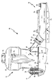
- FIG. 1 shows an oil module 10 in a side view.
- the oil module 10 has a Housing 11 and a receiving plate 12.
- the housing 11 has a lid 13 and a pot 14, wherein the lid 13 via a thread (not shown) releasably with the pot 14 is connected.
- the lid 13 has a hexagon 15, with which the lid 13 is screwed onto the pot 14.
- Both the lid 13, as well as the pot 14 is made of plastic.
- a filter element 16 is arranged, which the oil cleans. Instead of the filter element 16 but also other components in the Be integrated housing 11.
- the pot 14 has via screwing 17, in which metallic sleeves 18 are arranged. Through these sleeves 18 extend screws 19 therethrough.
- the inside diameter "d" of the Sleeve 18 is greater than the outer diameter "D" of the screw 19th
- the mounting surface may be affected by engine components such as e.g. a cylinder bank 21 are formed.
- the pot 14 has a pipe socket 22, which projects into a nozzle receptacle 23.
- the nozzle receptacle 23 is on the receiving plate 12 arranged.
- the receiving plate 12 is provided with hexagon screws 24 attached to an engine block 25. However, for fixing the receiving plate 12 Other screws, as known in the art are used.
- the engine block 25 has channel lines (not shown) through which the oil for Receiving plate 12 is passed.
- the receiving plate 12 are the channels for the crude oil sealingly separated from the pure oil.
- the mounting surface 20 is parallel to the mounting area arranged on the engine block 25, wherein between the mounting locations a Height difference .DELTA.H is present, which through the pipe socket 22 and the nozzle receiving 23 is bridged.
- a disk-shaped dirt collar 26th is arranged, which prevents coarse dirt from entering the nozzle receptacle 23.
- the pipe socket 22 remains in the nozzle receptacle 23 and during assembly does not slip out of control, a clamp 27 is provided, which by the Stutzenability 23 passes through the pipe socket 22 and this against slipping out guaranteed.
- the pipe socket 22 in the nozzle receptacle 23 By the clamp 27, the pipe socket 22 in the nozzle receptacle 23, however, sufficient clearance to compensate for tolerances, whereby a tension-free, sealing connection exists.
- This connection can bridge distances, causing the oil from a hard to reach place in the engine compartment to the place is passed, at which the oil treatment, in particular cleaning or cooling done can.
- the oil module 10 is shown in Figure 1 in plan view.
- the figure 1 corresponding Components are provided with the same reference numerals.
- the housing 11 has two pipe sockets 22.
- the first pipe socket forms an inlet 28 and the second pipe socket forms an outlet 29.
- the Inlet 28 passes the oil into the housing 11, where it passes through the filter element 16 (see Figure 1) is cleaned and through the outlet 29, the purified oil comes out of the Housing 11 off.
- Connect the two nozzle receptacles 23 on the receiving plate 12 the pipe socket 22 with the respective oil channels (not shown) in the engine block 25. Die Staple 27 fixes both pipe sockets 22 in the respective nozzle receiving 23.
- the pipe socket 22 with all Geometries finished without rework and molded, whereby the housing 11 is made in one piece with the pipe socket 22.
- the housing 11th As a metal part, the pipe socket 22 in a mechanical processing step produced.
- FIG. 3 shows an alternative embodiment of the oil module 10 in plan view.
- this embodiment differs in that only a single pipe socket 22 is provided, which according to the arrows the inlet 28 and the outlet 29 forms.
- the pipe socket 22 has inside over separate channels. Since a single pipe socket is present, is only a single Nozzle holder 23 required.
- the connection between the pipe socket 22 and the Spout receptacle 23 is secured as in Figure 2 with a bracket 27.
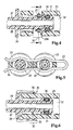
- FIG 4 the pipe connection of the pipe socket 22 and the nozzle receptacle 23rd in longitudinal section along the section line A-A in Figure 1 shown.
- the figure 1 or 2 corresponding Components are provided with the same reference numerals.
- the pipe socket 22 has in its end region via a sealing groove 30 in which an O-seal 31st is arranged.
- the O-seal 31 may move within the seal groove 30, wherein the O-seal on the oil passage 32 formed by the nozzle receptacle 23 sealingly rests.
- the clamp 27 engages in a securing region 33 in the nozzle receptacle 23 on.
- the securing region 33 is a, introduced into the nozzle receptacle 23 Groove 23a.
- the bracket 27 can axial movements run, with the clip 27 rests against the pipe socket 22 and this against slipping out secures.
- FIG. 6 shows an alternative embodiment of the pipe connection in longitudinal section.
- this embodiment has the pipe connection Snap hooks 35 which are arranged on the dirt collar 26.
- the snap hooks 35 radially outwardly via locking lugs 36, which at the nozzle receiving 23 are arranged.
- the locking lugs 36 can also Eyelets (not shown) may be provided, through which the snap hooks 35 reach through.
- the number of snap hooks 35 can be adapted to the forces to be absorbed become.
- the snap hooks 35 if more than a snap hook 35 is provided, evenly distributed around the circumference, or on one side in be arranged closer distances.
Landscapes
- Engineering & Computer Science (AREA)
- Mechanical Engineering (AREA)
- General Engineering & Computer Science (AREA)
- Lubrication Details And Ventilation Of Internal Combustion Engines (AREA)
Applications Claiming Priority (2)
| Application Number | Priority Date | Filing Date | Title |
|---|---|---|---|
| DE200410014787 DE102004014787A1 (de) | 2004-03-24 | 2004-03-24 | Ölmodul |
| DE102004014787 | 2004-03-24 |
Publications (1)
| Publication Number | Publication Date |
|---|---|
| EP1580409A2 true EP1580409A2 (fr) | 2005-09-28 |
Family
ID=34854059
Family Applications (1)
| Application Number | Title | Priority Date | Filing Date |
|---|---|---|---|
| EP20050101961 Withdrawn EP1580409A2 (fr) | 2004-03-24 | 2005-03-14 | Ensemble modulaire de lubrification |
Country Status (2)
| Country | Link |
|---|---|
| EP (1) | EP1580409A2 (fr) |
| DE (1) | DE102004014787A1 (fr) |
Cited By (1)
| Publication number | Priority date | Publication date | Assignee | Title |
|---|---|---|---|---|
| US12078090B1 (en) | 2024-02-29 | 2024-09-03 | Skyward Automotive Products LLC | Oil filter housing and assembly |
Families Citing this family (2)
| Publication number | Priority date | Publication date | Assignee | Title |
|---|---|---|---|---|
| DE202008010221U1 (de) * | 2008-07-31 | 2009-12-10 | Mann+Hummel Gmbh | Filtereinrichtung mit einem Filtergehäuse zur Aufnahme eines Filterelements |
| DE102021117059B4 (de) | 2021-07-02 | 2023-03-30 | Audi Aktiengesellschaft | Antriebsvorrichtung für eine elektrifizierte Fahrzeugachse |
Family Cites Families (5)
| Publication number | Priority date | Publication date | Assignee | Title |
|---|---|---|---|---|
| CA1107318A (fr) * | 1978-05-15 | 1981-08-18 | Sealed Power Corporation | Raccord de tuyauterie, et mode de montage connexe |
| DE4223250A1 (de) * | 1992-07-15 | 1994-01-20 | Continental Ag | Automatisch montierbare Steckkupplung für Leitungsschläuche in Kraftfahrzeugen |
| DE19626867A1 (de) * | 1996-07-04 | 1998-01-29 | Daimler Benz Ag | An ein Kurbelgehäuse eines Verbrennungsmotors anflanschbares Trägerteil für Aggregate der Schmier-Ölversorgung und -behandlung |
| EP0838577B1 (fr) * | 1996-10-26 | 2001-10-24 | MAHLE Filtersysteme GmbH | Système d'amenée d'huile pour moteur à combustion |
| DE29915384U1 (de) * | 1999-09-02 | 2001-01-18 | Ing. Walter Hengst GmbH & Co. KG, 48147 Münster | Kombination aus einer Haupteinheit und wenigstens einer Anbau-Funktionseinheit |
-
2004
- 2004-03-24 DE DE200410014787 patent/DE102004014787A1/de not_active Withdrawn
-
2005
- 2005-03-14 EP EP20050101961 patent/EP1580409A2/fr not_active Withdrawn
Cited By (2)
| Publication number | Priority date | Publication date | Assignee | Title |
|---|---|---|---|---|
| US12078090B1 (en) | 2024-02-29 | 2024-09-03 | Skyward Automotive Products LLC | Oil filter housing and assembly |
| US12655779B2 (en) | 2024-02-29 | 2026-06-16 | Skyward Automotive Products LLC | Oil filter housing and assembly |
Also Published As
| Publication number | Publication date |
|---|---|
| DE102004014787A1 (de) | 2005-10-13 |
Similar Documents
| Publication | Publication Date | Title |
|---|---|---|
| EP0748646B1 (fr) | Filtre de liquide | |
| EP1154831B1 (fr) | Filtre a liquide comprenant un element central demontable et un element de maintien supplementaire | |
| EP2620203A1 (fr) | Filtre pour l'air d'admission de moteurs à combustion interne | |
| EP2070575A1 (fr) | Filtre à huile | |
| EP3659692A1 (fr) | Boîtier, couvercle de boîtier et élément de liaison d'un dispositif de séparation d'au moins un fluide d'un gaz et dispositif de séparation d'un fluide | |
| EP2845636B1 (fr) | Élément de filtre et procédé de fabrication d'un élément de filtre | |
| DE102011010076A1 (de) | Filterelement eines Flüssigkeitsfilters und Flüssigkeitsfilter | |
| EP4048426B1 (fr) | Dispositif de traitement pour traiter des fluides, en particulier des fluides liquides, et tête de raccordement pour un dispositif de traitement | |
| DE112014005458B4 (de) | Filterelement und Filtersystem mit Nebenstromfilterung | |
| DE102013014494A1 (de) | Filtersystem mit Dichtung | |
| EP2888023B1 (fr) | Dispositif de filtration, en particulier pour la filtration de gaz | |
| DE29915844U1 (de) | Filter mit Ventil-Kombinationsbauteil | |
| EP1669121A2 (fr) | filtre de liquide | |
| DE102015008328B4 (de) | Filteranschlusseinrichtung und Filtereinrichtung | |
| DE102016008732B4 (de) | Fluidgehäuse eines Fluidbehandlungssystem und Fluidbehandlungssystem | |
| DE19743615B4 (de) | Airbagbaueinheit | |
| EP3414436B1 (fr) | Système de sortie de gaz d'échappement pour un véhicule automobile, véhicule automobile doté d'un tel système de sortie de gaz d'échappement et procédé de production d'un système de sortie de gaz d'échappement | |
| WO2013178299A1 (fr) | Dispositif de filtration et procédé de fabrication d'un dispositif de filtration | |
| DE102004014787A1 (de) | Ölmodul | |
| DE102017004558B4 (de) | Gehäusemodul eines Fluidbehandlungsmoduls und Fluidbehandlungsmodul | |
| DE102014005348B4 (de) | Filterelement eines Filters und Filter | |
| EP2043754A1 (fr) | Groupe echangeur thermique pour liquide | |
| EP1090666A1 (fr) | Filtre à liquide connecté aux tuyaux souples | |
| DE29916082U1 (de) | Flüssigkeitsfilter | |
| DE29915384U1 (de) | Kombination aus einer Haupteinheit und wenigstens einer Anbau-Funktionseinheit |
Legal Events
| Date | Code | Title | Description |
|---|---|---|---|
| PUAI | Public reference made under article 153(3) epc to a published international application that has entered the european phase |
Free format text: ORIGINAL CODE: 0009012 |
|
| AK | Designated contracting states |
Kind code of ref document: A2 Designated state(s): AT BE BG CH CY CZ DE DK EE ES FI FR GB GR HU IE IS IT LI LT LU MC NL PL PT RO SE SI SK TR |
|
| AX | Request for extension of the european patent |
Extension state: AL BA HR LV MK YU |
|
| STAA | Information on the status of an ep patent application or granted ep patent |
Free format text: STATUS: THE APPLICATION IS DEEMED TO BE WITHDRAWN |
|
| 18D | Application deemed to be withdrawn |
Effective date: 20091001 |