EP1580371A2 - Beschlaganordnung - Google Patents
Beschlaganordnung Download PDFInfo
- Publication number
- EP1580371A2 EP1580371A2 EP05003667A EP05003667A EP1580371A2 EP 1580371 A2 EP1580371 A2 EP 1580371A2 EP 05003667 A EP05003667 A EP 05003667A EP 05003667 A EP05003667 A EP 05003667A EP 1580371 A2 EP1580371 A2 EP 1580371A2
- Authority
- EP
- European Patent Office
- Prior art keywords
- locking bar
- gear rod
- coupling portion
- coupling
- fitting arrangement
- Prior art date
- Legal status (The legal status is an assumption and is not a legal conclusion. Google has not performed a legal analysis and makes no representation as to the accuracy of the status listed.)
- Granted
Links
Images


Classifications
-
- E—FIXED CONSTRUCTIONS
- E05—LOCKS; KEYS; WINDOW OR DOOR FITTINGS; SAFES
- E05C—BOLTS OR FASTENING DEVICES FOR WINGS, SPECIALLY FOR DOORS OR WINDOWS
- E05C9/00—Arrangements of simultaneously actuated bolts or other securing devices at well-separated positions on the same wing
- E05C9/02—Arrangements of simultaneously actuated bolts or other securing devices at well-separated positions on the same wing with one sliding bar for fastening when moved in one direction and unfastening when moved in opposite direction; with two sliding bars moved in the same direction when fastening or unfastening
-
- E—FIXED CONSTRUCTIONS
- E05—LOCKS; KEYS; WINDOW OR DOOR FITTINGS; SAFES
- E05C—BOLTS OR FASTENING DEVICES FOR WINGS, SPECIALLY FOR DOORS OR WINDOWS
- E05C9/00—Arrangements of simultaneously actuated bolts or other securing devices at well-separated positions on the same wing
- E05C9/20—Coupling means for sliding bars, rods, or cables
Definitions
- the present invention relates to a fitting arrangement for windows, Doors or the like with a sliding over a transmission gear rod and with a locking bar to be coupled to the gear rod, wherein on the gear rod, a gear rod coupling portion and provided on the locking bar a locking bar coupling portion over which the transmission rod and the locking bar to the common Move with each other are coupled.
- the getriebeferne End of the gear rod on both sides e.g. with external teeth provided, extending over a larger area of the gear rod extend.
- the locking bar part or continuation a bar exclusion or a corner drive, each with The transmission rod can be coupled to a movement of the transmission via an actuating handle in a corresponding movement of the rod exclusion or the corner deflection implement.
- a so-called tooth box arranged, which has a U-shaped cross section, wherein the inside long sides of the tooth box counter teeth for the teeth provided at the free end of the transmission rod formed are.
- the free end of the gear rod can with its teeth be used in the Schmidtveriereung of the tooth box, so that the teeth in the direction of displacement of the gear rod an undercut form and thus the locking bar together with the gear rod is displaceable.
- the present invention is based on the object, a fitting arrangement specify the type mentioned, the fast, safe and precise mounting including adjustment allows.
- the assembly of an inventively designed Fitting arrangement simplified while maintaining a safe and secure precise adjustment possible.
- the gearbox the fitting assembly inserted into the frame, whereby the Gear rod is brought into the desired position.
- the transmission rod coupling section and the locking bar coupling portion are in their release position, in which a move the Lock bar against the gear rod is possible.
- the locking bar After insertion the fitting in the wing receiving groove, the locking bar so far shifted relative to the transmission rod until the locking bar the desired Position has taken and the total length of the fitting assembly thus has the desired length.
- this position can For example, associated with the locking bar corner or a corresponding positioning exactly at the corner of the frame issue.
- the transmission rod coupling portion a toothing and on the locking bar coupling portion a cooperating with the gearing Provided counter toothing over which the gear rod and the Lock bar can be coupled together.
- the teeth is a quasi-continuous mutual adjustment of locking bar and Gear rod possible.
- other suitable fasteners such as pins and holes be used.
- the locking bar as an extension the gear rod usually aligned with this in a plane arranged. Only the relatively short tooth box is offset Level of the locking bar and gear rod arranged to the aligned To allow arrangement of the two rods. Through this aligned Arrangement is in the known fitting arrangements, however Adjustment game reduced to the relatively short length of the tooth box, because when moving further, the frontal free end of the gear rod at the end, arranged in the same plane end of Bar rod abuts and thus another mutual displacement and adjustment possibility is prevented.
- gear rod and / or the locking bar along the face plate are displaceable and the faceplate forms a support for the retaining element against the bias.
- gear rod, the locking bar and the Faceplate Preferably form the gear rod, the locking bar and the Faceplate a preassembled unit, whereby the handling in the Adjustment to known, consisting of several parts fitting arrangements is significantly simplified.
- the Holding element on the faceplate is achieved that the locking bar in the release position substantially free of frictional forces, which caused by the bias remains, and thus easy can be moved during the desired adjustment.
- a receiving opening for the retaining element in the face plate educated.
- the retaining element in the receiving opening fixed against displacement by the bias, in particular screwed, locked or pressed.
- a thread for a trained as a screw holding element be formed, so that the retaining element through the faceplate can be screwed through and with his free end, for example the transmission rod coupling portion against the bias from the guided between the transmission rod and the face plate Lock bar pushes away and thus gear rod and locking bar in holding their release position.
- the Transmission rod coupling portion as separated from the transmission rod Coupling formed.
- the coupling part can essentially transversely, in particular perpendicular to the gear rod, against the bias be designed to be displaceable and in particular in one Guiding opening to be arranged, which formed in the transmission rod is.
- the transmission rod in the release position relaxed, arranged substantially parallel to the locking bar be because only the separate coupling part of the holding element against the bias must be maintained across the transmission rod so that the coupling member not with the locking bar coupling portion in Intervention is.
- the transmission rod coupling portion is integrally formed with the gear rod and for taking the release position, for example, the transmission rod coupling portion thus forming free end of the transmission rod bent away from the locking bar, that no coupling between consists of these two elements.
- the gear rod inherent elasticity the bias of the invention Create fitting arrangement.
- the coupling part may preferably have an inner and / or a have external teeth.
- the coupling part for example, on his Top a coupling region, for example with a toothing, having, with a corresponding counter element, for example a counter-toothing on the locking bar are brought into engagement can.
- the Locking rod coupling portion formed integrally with the locking bar.
- the locking bar coupling section preferably comprises a trained in particular as a slot adjustment hole whose boundary at least partially as a counter-toothing, in particular as a counter-toothing for the toothing of the coupling part, is formed.
- a separate spring element is preferred, in particular provided a leaf spring. It is advantageous that Coupling part by means of the spring element through the guide opening slidable into the adjusting opening. The bias but can also by an elastic part of the locking bar and / or the gear rod are generated.
- a support surface for the Holding element is at the transmission rod coupling portion a support surface for the Holding element formed. Due to the support surface are a defined and secure support of the transmission rod coupling portion the holding element and thus a secure adjustment of the release position guaranteed.
- the support surface can be formed so long that even with an actuation of the transmission and an associated Moving the gear rod, the holding element on the support surface supported and thus in this case the release position is held securely.
- a predetermined breaking point is formed integral with the transmission rod coupling portion formed between the transmission rod coupling portion and holding element.
- the retaining element also from the transmission rod coupling portion be formed separately and connected to this, for example screwed, glued or otherwise attached to this.
- a predetermined breaking point can be provided according to the invention be, between a part to be separated from the holding element and a remaining, connected to the transmission rod coupling portion Part is arranged.
- the locking bar by moving to the desired position to subsequently by moving the gear rod by means of an actuation of the Getriebes the transmission rod coupling section to move so far until the holding element is aligned with the receiving opening in the Faceplate comes to rest.
- this position eliminates the supporting effect the faceplate, so that the retaining element together with the Transmission rod coupling portion due to the bias in the direction the face plate is moved, while the holding element in the Receiving opening of the faceplate occurs and the transmission rod coupling section in engagement with the locking bar coupling portion comes, so the position of the adjusted locking bar is fixed.
- a further actuation of the transmission is the Retaining element by the further displacement of the gear rod opposite sheared off the face plate, so that now adjusted to each other Driving and locking bars are freely displaceable with each other.
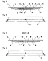
- Fig. 1 shows a fitting assembly 1, a faceplate 2, a below the face plate parallel to this extending gear rod 4th and one disposed between the face-plate rail 2 and the transmission rod 4, includes parallel to these extending locking bar 3.
- the gear rod 4 is seated in its illustrated in Fig. 1 right Range continues to a gearbox, not shown, about which they are in Longitudinal direction parallel to the faceplate 2 and the locking bar 3 in usual way according to an arrow 5 is displaced.
- the illustrated in Fig. 1 left end of the locking bar 3 also continues and may for example a bar exclusion form or connected to a corner drive. It is arranged between the face plate 2 and the transmission rod 4 Locking rod 3 also displaced in the longitudinal direction, as by an arrow 6 is indicated.
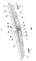
- a guide hole 7 is formed in the one formed as a tooth block coupling part 8 transverse to the gear rod 4th slidably arranged.
- the coupling part 8 has at its two opposite longitudinal sides in each case a toothing 9, of which in Fig. 1 only out pointing out of the image plane toothing 9 recognizable is.
- a support surface 10 is formed, at which a designed as a screw 11 holding member 12 with supports its free end.
- the screw 11 is provided by a provided in the faceplate 2 threaded hole 13 passed and through the thread against displacement secured in the longitudinal direction of the threaded hole 13 out.
- a leaf spring 14 is attached, the central region on the underside of the coupling part 8 under Preload is applied.
- the coupling part 8 is through the tensioned Leaf spring 14 is pressed in the direction of the screw 11, so that the coupling part 8 with its support surface 10 under bias against the free End of the screw 11 is present.
- the locking bar 3 is formed as a slot 15 adjustment hole 16, which extends in the longitudinal direction of the locking bar 3.
- the both longitudinal sides of the adjusting opening 16 are as counter teeth 17 formed in Fig. 1 due to the sectional view only in the Image plane rear counter teeth 17 is shown.
- the width of the adjustment opening 16 and the size of the counter teeth 17 is according to the width of the coupling part 8 and their Gears selected 9, so that when inserting the coupling member 8 in the adjustment opening 16, the teeth 9 with the counter toothing 17 engage and a longitudinal displacement of the coupling part. 8 relative to the locking bar 3 is prevented, as it in particular Fig. 6 can be seen.
- Fig. 1 In the position shown in Fig. 1 is a free displacement of the locking bar 3 and thus the locking bar coupling portion 19 possible because a penetration of the coupling part 8 due to the bias by the leaf spring 14 is prevented by means of the screw 11.
- the in Fig. 1 shown position thus forms a release position for the transmission rod coupling portion 18 and the locking bar coupling portion 19, in which the two coupling sections 18, 19 by the leaf spring 14 transverse to the direction 5 of the transmission rod are biased against each other, due to the screw 11 but the two coupling portions 18, 19 are decoupled from each other and Thus, a displacement of the locking bar 3 relative to the transmission rod. 4 is possible.
- the screw 11 protrudes through the adjusting hole 16 and has a smaller diameter than the inside diameter of the adjustment hole 16, so that a displacement of the locking bar 3 by the screw 11 is not obstructed.
- Fig. 1 The release position described for Fig. 1 is also from the longitudinal section to recognize in FIG. 3. It is clear to see that the faceplate 2, the locking bar 3 and the gear rod 4 in different, parallel planes are located and the coupling part 8 by the screw 11 out of engagement with the counter toothing 17th the adjustment hole 16 is held. Furthermore, it can be seen from FIG. 3 that the screw 11 in an alternative embodiment in the support surface 10 of the coupling part 8 can be screwed into it.
- FIGS. 4 and 5 in contrast to FIGS. 1 to 3, the screw 11th unscrewed from the threaded hole 13.
- the coupling part 8 through the Bias of the leaf spring 14 in the direction of the transmission rod coupling portion 18 urged and enters its adjustment opening 16th one.
- the teeth 9 of the coupling part 8 arrive with the Counter teeth 17 of the adjusting hole 16 in engagement, as shown in Fig. 6 is shown.
- the fitting arrangement according to the invention is used as follows.
- fitting assembly 1 To adjust the fitting assembly 1 is first by moving the locking bar 3 outward as far outward to its maximum Length pulled apart. Subsequently, the fitting assembly 1 used in the Betschagenut the door or window frame, so that attached to the faceplate 2 gear box in a corresponding Opening in the frame comes to rest.
- the locking bar 3 As long as shifted in the direction of the gearbox until the Fitting arrangement is adapted to the size of the frame and the Lock bar 3 their desired position (for example, with aligned Eckumlenkung or aligned positioning) has reached.
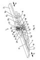
- FIGS. 7 to 9 will be three further embodiments of the invention. There are parts that are already described Parts in Figs. 1 to 6 correspond to the same Reference numerals as shown in FIGS. 1 to 6 provided.
- Fig. 7 differs from the previously described Embodiment in that the retaining element 12 is not is formed by a screw, but by a locking element 20.
- the faceplate 2 is a bore 21 instead of the threaded hole 13 provided, through which the latching element 20 is passed.
- the locking element 20 has at its outer end a handle 22 at a shaft 25 connects.
- an at least partially encircling annular bead trained locking portion 23 is provided, whose outer width is greater is than the diameter of the bore 21.
- Faceplate 2 penetrating shaft 25 has a longitudinal slot 24, so that despite the larger outer diameter of the locking portion 23 of the shaft 25 can be plugged through the bore 21 in the face-plate 2, by the two halves of the shaft delimiting the longitudinal slot 24 25 are compressed.
- the free end of the shaft 25 of the locking element 20 is located on the support surface 10 of the coupling part 8, wherein a pushing back of the locking element 20 from the bore 21 due to the bias of the leaf spring 14 by the larger outer diameter of the locking portion 23rd is prevented.
- the fitting arrangement according to Fig. 7 is analogous to the fitting arrangement used according to FIGS. 1 to 6, wherein the automatic Fixing the adjusted fitting arrangement only the locking element 20 taken on the handle 22 and pulled out of the bore 21 becomes.
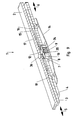
- the holding element 12 comprises a Screw 26 with internal thread 27, which rotatable in a cap 28 is stored.
- the cap 28 has on its underside pin 29, which engage in provided on the faceplate 2 openings 30, so that a fixation of the cap 28 at the top of the faceplate 2 takes place.
- a screw bolt 31 is screwed, at its underside shown in Fig. 8 with the coupling part 8 is connected.
- the joint between the bolt 31 and the coupling part 8 is formed as a predetermined breaking point 32.
- Fig. 8 thus shows the Release position in which the locking bar 3 for adjusting the fitting arrangement 1 is substantially freely displaceable.
- the screw 26 For conversion into the coupling position, the screw 26 is rotated, so that the bolt 31 via the internal thread 27 in an inside lying cavity 33 is pulled into the screw 26. simultaneously is also connected to the bolt 31 coupling part 8th shifted in Fig. 8 upwards so that it enters the adjustment opening 16 and a coupling between the transmission rod 4 and the locking bar 3 takes place.
- the bolt tears 31 at the predetermined breaking point 32, so that a displacement of the coupling part 8 together with the gear rod 4 when operating the transmission is possible.
- Fig. 9 is at the top of the coupling part 8 a pin 34 attached, wherein the connection between the pin 34 and the coupling part 8 in turn forms a predetermined breaking point 35.
- the pin 34 is supported by its free end on the underside of the Faceplate 2 from, thereby preventing the coupling part 8th due to the bias of the leaf spring 14 in the adjustment hole sixteenth penetrates.
- the transmission rod 4 is then returned via the transmission. or moved in the same direction, which is in the shearing opening 36 located pin 34 sheared off from the coupling part 8 so that the transmission rod 4 together with the locking bar 3 is freely displaceable over the transmission.
Landscapes
- Engineering & Computer Science (AREA)
- Mechanical Engineering (AREA)
- Mutual Connection Of Rods And Tubes (AREA)
- Lock And Its Accessories (AREA)
- Connection Of Plates (AREA)
- Earth Drilling (AREA)
- Piezo-Electric Or Mechanical Vibrators, Or Delay Or Filter Circuits (AREA)
- Fittings On The Vehicle Exterior For Carrying Loads, And Devices For Holding Or Mounting Articles (AREA)
Abstract
Description
- Fig. 1.
- eine teilweise geschnittene, perspektivische Darstellung einer erfindungsgemäß ausgebildeten Beschlaganordnung,
- Fig. 2
- eine Draufsicht auf die Beschlaganordnung nach Fig. 1,
- Fig. 3
- einen Längsschnitt durch die Beschlaganordnung nach Fig. 1,
- Fig. 4
- eine Draufsicht auf die Beschlaganordnung nach Fig. 1 in der Kopplungsposition,
- Fig. 5
- einen Längsschnitt durch die Beschlaganordnung in der Kopplungsposition nach Fig. 4,
- Fig. 6
- eine Draufsicht auf einen Teil der Beschlaganordnung nach Fig. 1 und
- Fig. 7 - 9
- weitere Ausführungsformen der Erfindung.
- 1
- Beschlaganordnung
- 2
- Stulpschiene
- 3
- Riegelstange
- 4
- Getriebestange
- 5
- Pfeil
- 6
- Pfeil
- 7
- Führungsöffnung
- 8
- Kopplungsteil
- 9
- Verzahnung
- 10
- Abstützfläche
- 11
- Schraube
- 12
- Halteelement
- 13
- Gewindebohrung
- 14
- Blattfeder
- 15
- Langloch
- 16
- Justieröffnung
- 17
- Gegenverzahnung
- 18
- Getriebestangen-Kopplungsabschnitt
- 19
- Riegelstangen-Kopplungsabschnitt
- 20
- Rastelement
- 21
- Bohrung
- 22
- Handhabe
- 23
- Rastabschnitt
- 24
- Längsschlitz
- 25
- Schaft
- 26
- Schraube
- 27
- Innengewinde
- 28
- Abdeckkappe
- 29
- Zapfen
- 30
- Öffnung
- 31
- Schraubbolzen
- 32
- Sollbruchstelle
- 33
- Hohlraum
- 34
- Zapfen
- 35
- Sollbruchstelle
- 36
- Abscheröffnung
Claims (20)
- Beschlaganordnung für Fenster, Türen oder dergleichen mit einer über ein Getriebe verschiebbaren Getriebestange (4) und mit einer an die Getriebestange (4) anzukoppelnden Riegelstange (3), wobei an der Getriebestange (3) ein Getriebestangen-Kopplungsabschnitt (18) und an der Riegelstange (3) ein Riegelstangen-Kopplungsabschnitt (19) vorgesehen sind, über die die Getriebestange (4) und die Riegelstange (3) zum gemeinsamen Verschieben miteinander koppelbar sind,
dadurch gekennzeichnet,dass der Getriebestangen-Kopplungsabschnitt (18) und der Riegelstangen-Kopplungsabschnitt (19) zwischen einer definierten Freigabeposition, in der die beiden Kopplungsabschnitte (18, 19) nicht ineinander greifen, und einer Kopplungsposition, in der die beiden Kopplungsabschnitte (18, 19) ineinander greifen, verstellbar sind,dass in der Freigabepositiona) der Getriebestangen-Kopplungsabschnitt (18) und der Riegelstangen-Kopplungsabschnitt (19) im Wesentlichen quer zur Verschieberichtung (5) der Getriebestange (4) gegeneinander vorgespannt sind,b) die beiden Kopplungsabschnitte (18, 19) gegen die Vorspannung durch ein Halteelement (12) in ihrer vorgespannten Position gehalten werden undc) die Riegelstange (3) gegenüber der Getriebestange (4) zumindest bereichsweise verschiebbar istund dass das Halteelement (12) entfernbar ist und ohne Halteelement (12) die beiden Kopplungsabschnitte (18, 19) durch die Vorspannung automatisch in die Kopplungsposition überführbar sind. - Beschlaganordnung nach Anspruch 1,
dadurch gekennzeichnet, dass an dem Getriebestangen-Kopplungsabschnitt (18) eine Verzahnung (9) und an dem Riegelstangen-Kopplungsabschnitt (19) eine mit der Verzahnung (9) zusammenwirkende Gegenverzahnung (17) vorgesehen sind, über die die Getriebestange (4) und die Riegelstange (3) miteinander koppelbar sind. - Beschlaganordnung nach Anspruch 1 oder 2,
dadurch gekennzeichnet, dass die Riegelstange (3) im Bereich des Riegelstangen-Kopplungsabschnitts (19) und die Getriebestange (4) im Bereich des Getriebestangen-Kopplungsabschnitts (18) in gegeneinander versetzten Ebenen, einander überlappend angeordnet sind. - Beschlaganordnung nach einem der vorhergehenden Ansprüche,
dadurch gekennzeichnet, dass eine Stulpschiene (2) vorgesehen ist, dass die Getriebestange (4) und/oder die Riegelstange (3) entlang der Stulpschiene (2) verschiebbar sind und dass die Stulpschiene (2) eine Abstützung für das Halteelement (12) gegen die Vorspannung bildet. - Beschlaganordnung nach Anspruch 4,
dadurch gekennzeichnet, dass Getriebestange (4), Riegelstange (3) und Stulpschiene (2) als zusammenhängende Einheit vormontiert sind. - Beschlaganordnung nach Anspruch 4 oder 5,
dadurch gekennzeichnet, dass in der Stulpschiene (2) eine Aufnahmeöffnung (13,21,36) für das Halteelement (12) ausgebildet ist. - Beschlaganordnung nach Anspruch 6,
dadurch gekennzeichnet, dass das Halteelement (12) in der Aufnahmeöffnung (13, 21) gegen ein Verschieben durch die Vorspannung fixiert, insbesondere verschraubt, verrastet oder verpresst ist. - Beschlaganordnung nach einem der vorhergehenden Ansprüche,
dadurch gekennzeichnet, dass der Getriebestangen-Kopplungsabschnitt (18) als von der Getriebestange (4) getrenntes Kopplungsteil (8) ausgebildet ist. - Beschlaganordnung nach Anspruch 8,
dadurch gekennzeichnet, dass das Kopplungsteil (8) im Wesentlichen quer zur Getriebestange (4), gegen die Vorspannung verschiebbar ausgebildet ist, insbesondere dass in der Getriebestange (4) eine Führungsöffnung (7) für das Kopplungsteil (8) ausgebildet ist. - Beschlaganordnung nach Anspruch 8 oder 9,
dadurch gekennzeichnet, dass das Kopplungsteil (8) eine innen liegende und/oder eine außen liegende Verzahnung (9) aufweist. - Beschlaganordnung nach einem der Ansprüche 8 bis 10,
dadurch gekennzeichnet, dass das Kopplungsteil (8) an zumindest einer Außenseite, insbesondere an zwei gegenüberliegenden Außenseiten eine Verzahnung (9) aufweist. - Beschlaganordnung nach einem der Ansprüche 1 bis 7,
dadurch gekennzeichnet, dass der Getriebestangen-Kopplungsabschnitt (18) einstückig mit der Getriebestange (4) ausgebildet ist. - Beschlaganordnung nach einem der vorhergehenden Ansprüche,
dadurch gekennzeichnet, dass der Riegelstangen-Kopplungsabschnitt (19) einstückig mit der Riegelstange (3) ausgebildet ist. - Beschlaganordnung nach einem der vorhergehenden Ansprüche,
dadurch gekennzeichnet, dass der Riegelstangen-Kopplungsabschnitt (19) eine insbesondere als Langloch (15) ausgebildete Justieröffnung (16) umfasst, deren Berandung zumindest teilweise als Gegenverzahnung (17) ausgebildet ist. - Beschlaganordnung nach einem der vorhergehenden Ansprüche,
dadurch gekennzeichnet, dass zur Erzeugung der Vorspannung ein separates Federelement, insbesondere eine Blattfeder (14) vorgesehen ist. - Beschlaganordnung nach einem der Ansprüche 9 bis 15,
dadurch gekennzeichnet, dass das Kopplungsteil mittels des Federelements (14) durch die Führungsöffnung hindurch in die Justieröffnung hinein verschiebbar ist. - Beschlaganordnung nach einem der vorhergehenden Ansprüche,
dadurch gekennzeichnet, dass die Vorspannung durch einen elastischen Teil der Riegelstange (3) und/oder der Getriebestange (4) erzeugt wird. - Beschlaganordnung nach einem der vorhergehenden Ansprüche,
dadurch gekennzeichnet, dass an dem Getriebestangen-Kopplungsabschnitt (18) eine Abstützfläche (10) für das Halteelement ausgebildet ist. - Beschlaganordnung nach einem der vorhergehenden Ansprüche,
dadurch gekennzeichnet, dass das Halteelement (12, 31, 34) einstückig mit dem Getriebestangen-Kopplungsabschnitt (18) ausgebildet ist, wobei zwischen dem Getriebestangen-Kopplungsabschnitt (18) und dem Halteelement (14, 31, 34) eine Sollbruchstelle (32, 35) ausgebildet ist. - Beschlaganordnung nach einem der vorhergehenden Ansprüche,
dadurch gekennzeichnet, dass das Halteelement (12) als Zapfen (20, 34) oder Schraube (11, 26) ausgebildet ist.
Applications Claiming Priority (2)
| Application Number | Priority Date | Filing Date | Title |
|---|---|---|---|
| DE202004003653U | 2004-03-09 | ||
| DE202004003653U DE202004003653U1 (de) | 2004-03-09 | 2004-03-09 | Beschlaganordnung |
Publications (3)
| Publication Number | Publication Date |
|---|---|
| EP1580371A2 true EP1580371A2 (de) | 2005-09-28 |
| EP1580371A3 EP1580371A3 (de) | 2007-09-26 |
| EP1580371B1 EP1580371B1 (de) | 2008-09-03 |
Family
ID=34802082
Family Applications (1)
| Application Number | Title | Priority Date | Filing Date |
|---|---|---|---|
| EP05003667A Expired - Lifetime EP1580371B1 (de) | 2004-03-09 | 2005-02-21 | Beschlaganordnung |
Country Status (3)
| Country | Link |
|---|---|
| EP (1) | EP1580371B1 (de) |
| AT (1) | ATE407280T1 (de) |
| DE (2) | DE202004003653U1 (de) |
Cited By (1)
| Publication number | Priority date | Publication date | Assignee | Title |
|---|---|---|---|---|
| US12435552B2 (en) * | 2020-09-28 | 2025-10-07 | Shenzhen Hopo Window Control Technology Co., Ltd | Driving device |
Families Citing this family (1)
| Publication number | Priority date | Publication date | Assignee | Title |
|---|---|---|---|---|
| DE102007017451A1 (de) * | 2007-04-02 | 2008-10-09 | Roto Frank Ag | Kraftübertragungsanordnung für ein Fenster, eine Tür oder dergleichen |
Family Cites Families (5)
| Publication number | Priority date | Publication date | Assignee | Title |
|---|---|---|---|---|
| DE2504420A1 (de) * | 1975-02-03 | 1976-08-05 | Fuhr C Fa | Treibstangenverschluss, insbesondere fuer fluegel von fenstern, tueren oder dergleichen |
| DE9114374U1 (de) * | 1991-11-18 | 1992-01-16 | Siegenia-Frank Kg, 5900 Siegen | Treibstangenbeschlag für Fenster, Türen o.dgl. |
| DE19607366A1 (de) * | 1996-02-27 | 1997-08-28 | Winkhaus Fa August | Treibstangenbeschlag-Montagesatz |
| DE29917245U1 (de) * | 1999-09-30 | 2000-01-05 | Siegenia-Frank Kg, 57074 Siegen | Beschlagteil |
| DE10151634A1 (de) * | 2001-10-17 | 2003-05-08 | Roto Frank Ag | Beschlag für ein Fenster, eine Tür oder dergleichen |
-
2004
- 2004-03-09 DE DE202004003653U patent/DE202004003653U1/de not_active Expired - Lifetime
-
2005
- 2005-02-21 AT AT05003667T patent/ATE407280T1/de active
- 2005-02-21 DE DE502005005231T patent/DE502005005231D1/de not_active Expired - Lifetime
- 2005-02-21 EP EP05003667A patent/EP1580371B1/de not_active Expired - Lifetime
Cited By (1)
| Publication number | Priority date | Publication date | Assignee | Title |
|---|---|---|---|---|
| US12435552B2 (en) * | 2020-09-28 | 2025-10-07 | Shenzhen Hopo Window Control Technology Co., Ltd | Driving device |
Also Published As
| Publication number | Publication date |
|---|---|
| DE202004003653U1 (de) | 2005-07-14 |
| DE502005005231D1 (de) | 2008-10-16 |
| EP1580371B1 (de) | 2008-09-03 |
| EP1580371A3 (de) | 2007-09-26 |
| ATE407280T1 (de) | 2008-09-15 |
Similar Documents
| Publication | Publication Date | Title |
|---|---|---|
| AT509414B1 (de) | Kupplungsvorrichtung mit seitenverstellung für eine schublade | |
| EP1151697B1 (de) | Verstellvorrichtung zur Neigungsverstellung der Frontblende einer Schublade | |
| EP1978187A1 (de) | Beschlaganordnung für ein Fenster, eine Tür oder dergleichen | |
| EP3156564B1 (de) | Koppelstift mit einstellbarer länge | |
| DE10240235A1 (de) | Verriegelungsvorrichtung für zwei relativ zueinander verschiebbar gelagerte Bauteile | |
| EP3266969B1 (de) | Eckumlenkung eines beschlages für einen flügel eines fensters oder einer tür | |
| DE8323365U1 (de) | Treibstangenbeschlag fuer fenster, tueren od. dgl. | |
| DE102010029051B4 (de) | Anschlaganordnung für schwenkbare Karosseriebauteile | |
| EP0671530B1 (de) | Beschlag für ein Fenster oder eine Türe | |
| EP3112577A1 (de) | Absenkdichtung | |
| EP2602412A2 (de) | Beschlaganordnung | |
| EP1580371B1 (de) | Beschlaganordnung | |
| DE102013005462A1 (de) | Zargenstützgestell, Bausatz für einen Türrahmen mit einem solchen Zargenstützgestell, Türrahmen mit einem solchen Zargenstützgestell und Verfahren zur Schaffung eines Türrahmens | |
| EP2343425B1 (de) | Beschlagteilschienen-Anordnung für ein Fenster, eine Tür, eine Klappe oder dergleichen | |
| EP1580370B1 (de) | Beschlaganordnung | |
| EP1746235B1 (de) | Beschlaganordnung | |
| EP3327228B1 (de) | Verriegelungsvorrichtung zum verriegeln und mitnehmen von mindestens zwei entlang einer ersten verschieberichtung und einer entgegengesetzten zweiten verschieberichtung verschiebbar gelagerten plattenförmigen elementen sowie wandandordnung mit mindestens zwei plattenförmigen elementen | |
| EP4163462B1 (de) | Schloss mit einem schlosskasten und einem dem schlosskasten gegenüberstehend anzuordnenden schliessblech | |
| DE102016004915B3 (de) | Beschlag für ein Fenster, Verfahren zum Herstellen des Beschlags sowie entsprechendes Fenster | |
| EP1724417A2 (de) | Schlosselement | |
| EP2801684B1 (de) | Getriebe-Baukastensystem | |
| DE2343933A1 (de) | Distanzhalter zwischen dem getriebegehaeuse eines einsteck-kantengetriebes und einer damit ueber ankerschrauben verbindbaren lagerrosette eines bedienungshebels | |
| EP3580415B1 (de) | Beschlaganordnung | |
| DE202005005121U1 (de) | Treibstangenantrieb | |
| EP1071859B1 (de) | Schliessvorrichtung für flügelfenster und flügeltüren |
Legal Events
| Date | Code | Title | Description |
|---|---|---|---|
| PUAI | Public reference made under article 153(3) epc to a published international application that has entered the european phase |
Free format text: ORIGINAL CODE: 0009012 |
|
| AK | Designated contracting states |
Kind code of ref document: A2 Designated state(s): AT BE BG CH CY CZ DE DK EE ES FI FR GB GR HU IE IS IT LI LT LU MC NL PL PT RO SE SI SK TR |
|
| AX | Request for extension of the european patent |
Extension state: AL BA HR LV MK YU |
|
| PUAL | Search report despatched |
Free format text: ORIGINAL CODE: 0009013 |
|
| AK | Designated contracting states |
Kind code of ref document: A3 Designated state(s): AT BE BG CH CY CZ DE DK EE ES FI FR GB GR HU IE IS IT LI LT LU MC NL PL PT RO SE SI SK TR |
|
| AX | Request for extension of the european patent |
Extension state: AL BA HR LV MK YU |
|
| 17P | Request for examination filed |
Effective date: 20071026 |
|
| 17Q | First examination report despatched |
Effective date: 20071127 |
|
| GRAP | Despatch of communication of intention to grant a patent |
Free format text: ORIGINAL CODE: EPIDOSNIGR1 |
|
| AKX | Designation fees paid |
Designated state(s): AT BE BG CH CY CZ DE DK EE ES FI FR GB GR HU IE IS IT LI LT LU MC NL PL PT RO SE SI SK TR |
|
| GRAS | Grant fee paid |
Free format text: ORIGINAL CODE: EPIDOSNIGR3 |
|
| GRAA | (expected) grant |
Free format text: ORIGINAL CODE: 0009210 |
|
| AK | Designated contracting states |
Kind code of ref document: B1 Designated state(s): AT BE BG CH CY CZ DE DK EE ES FI FR GB GR HU IE IS IT LI LT LU MC NL PL PT RO SE SI SK TR |
|
| REG | Reference to a national code |
Ref country code: GB Ref legal event code: FG4D Free format text: NOT ENGLISH |
|
| REG | Reference to a national code |
Ref country code: CH Ref legal event code: EP |
|
| REG | Reference to a national code |
Ref country code: IE Ref legal event code: FG4D Free format text: LANGUAGE OF EP DOCUMENT: GERMAN |
|
| REF | Corresponds to: |
Ref document number: 502005005231 Country of ref document: DE Date of ref document: 20081016 Kind code of ref document: P |
|
| REG | Reference to a national code |
Ref country code: HU Ref legal event code: AG4A Ref document number: E004017 Country of ref document: HU |
|
| PG25 | Lapsed in a contracting state [announced via postgrant information from national office to epo] |
Ref country code: NL Free format text: LAPSE BECAUSE OF FAILURE TO SUBMIT A TRANSLATION OF THE DESCRIPTION OR TO PAY THE FEE WITHIN THE PRESCRIBED TIME-LIMIT Effective date: 20080903 Ref country code: ES Free format text: LAPSE BECAUSE OF FAILURE TO SUBMIT A TRANSLATION OF THE DESCRIPTION OR TO PAY THE FEE WITHIN THE PRESCRIBED TIME-LIMIT Effective date: 20081214 Ref country code: LT Free format text: LAPSE BECAUSE OF FAILURE TO SUBMIT A TRANSLATION OF THE DESCRIPTION OR TO PAY THE FEE WITHIN THE PRESCRIBED TIME-LIMIT Effective date: 20080903 |
|
| PG25 | Lapsed in a contracting state [announced via postgrant information from national office to epo] |
Ref country code: SI Free format text: LAPSE BECAUSE OF FAILURE TO SUBMIT A TRANSLATION OF THE DESCRIPTION OR TO PAY THE FEE WITHIN THE PRESCRIBED TIME-LIMIT Effective date: 20080903 Ref country code: FI Free format text: LAPSE BECAUSE OF FAILURE TO SUBMIT A TRANSLATION OF THE DESCRIPTION OR TO PAY THE FEE WITHIN THE PRESCRIBED TIME-LIMIT Effective date: 20080903 |
|
| NLV1 | Nl: lapsed or annulled due to failure to fulfill the requirements of art. 29p and 29m of the patents act | ||
| REG | Reference to a national code |
Ref country code: IE Ref legal event code: FD4D |
|
| PG25 | Lapsed in a contracting state [announced via postgrant information from national office to epo] |
Ref country code: IE Free format text: LAPSE BECAUSE OF FAILURE TO SUBMIT A TRANSLATION OF THE DESCRIPTION OR TO PAY THE FEE WITHIN THE PRESCRIBED TIME-LIMIT Effective date: 20080903 Ref country code: BG Free format text: LAPSE BECAUSE OF FAILURE TO SUBMIT A TRANSLATION OF THE DESCRIPTION OR TO PAY THE FEE WITHIN THE PRESCRIBED TIME-LIMIT Effective date: 20081203 |
|
| PG25 | Lapsed in a contracting state [announced via postgrant information from national office to epo] |
Ref country code: RO Free format text: LAPSE BECAUSE OF FAILURE TO SUBMIT A TRANSLATION OF THE DESCRIPTION OR TO PAY THE FEE WITHIN THE PRESCRIBED TIME-LIMIT Effective date: 20080903 Ref country code: CZ Free format text: LAPSE BECAUSE OF FAILURE TO SUBMIT A TRANSLATION OF THE DESCRIPTION OR TO PAY THE FEE WITHIN THE PRESCRIBED TIME-LIMIT Effective date: 20080903 Ref country code: IS Free format text: LAPSE BECAUSE OF FAILURE TO SUBMIT A TRANSLATION OF THE DESCRIPTION OR TO PAY THE FEE WITHIN THE PRESCRIBED TIME-LIMIT Effective date: 20090103 Ref country code: SK Free format text: LAPSE BECAUSE OF FAILURE TO SUBMIT A TRANSLATION OF THE DESCRIPTION OR TO PAY THE FEE WITHIN THE PRESCRIBED TIME-LIMIT Effective date: 20080903 Ref country code: PT Free format text: LAPSE BECAUSE OF FAILURE TO SUBMIT A TRANSLATION OF THE DESCRIPTION OR TO PAY THE FEE WITHIN THE PRESCRIBED TIME-LIMIT Effective date: 20090203 |
|
| PLBE | No opposition filed within time limit |
Free format text: ORIGINAL CODE: 0009261 |
|
| STAA | Information on the status of an ep patent application or granted ep patent |
Free format text: STATUS: NO OPPOSITION FILED WITHIN TIME LIMIT |
|
| PG25 | Lapsed in a contracting state [announced via postgrant information from national office to epo] |
Ref country code: EE Free format text: LAPSE BECAUSE OF FAILURE TO SUBMIT A TRANSLATION OF THE DESCRIPTION OR TO PAY THE FEE WITHIN THE PRESCRIBED TIME-LIMIT Effective date: 20080903 Ref country code: DK Free format text: LAPSE BECAUSE OF FAILURE TO SUBMIT A TRANSLATION OF THE DESCRIPTION OR TO PAY THE FEE WITHIN THE PRESCRIBED TIME-LIMIT Effective date: 20080903 |
|
| 26N | No opposition filed |
Effective date: 20090604 |
|
| BERE | Be: lapsed |
Owner name: MAYER & CO. Effective date: 20090228 |
|
| PG25 | Lapsed in a contracting state [announced via postgrant information from national office to epo] |
Ref country code: IT Free format text: LAPSE BECAUSE OF FAILURE TO SUBMIT A TRANSLATION OF THE DESCRIPTION OR TO PAY THE FEE WITHIN THE PRESCRIBED TIME-LIMIT Effective date: 20080903 |
|
| PG25 | Lapsed in a contracting state [announced via postgrant information from national office to epo] |
Ref country code: MC Free format text: LAPSE BECAUSE OF NON-PAYMENT OF DUE FEES Effective date: 20090228 |
|
| REG | Reference to a national code |
Ref country code: CH Ref legal event code: PL |
|
| PG25 | Lapsed in a contracting state [announced via postgrant information from national office to epo] |
Ref country code: LI Free format text: LAPSE BECAUSE OF NON-PAYMENT OF DUE FEES Effective date: 20090228 Ref country code: CH Free format text: LAPSE BECAUSE OF NON-PAYMENT OF DUE FEES Effective date: 20090228 |
|
| PG25 | Lapsed in a contracting state [announced via postgrant information from national office to epo] |
Ref country code: SE Free format text: LAPSE BECAUSE OF FAILURE TO SUBMIT A TRANSLATION OF THE DESCRIPTION OR TO PAY THE FEE WITHIN THE PRESCRIBED TIME-LIMIT Effective date: 20081203 |
|
| PG25 | Lapsed in a contracting state [announced via postgrant information from national office to epo] |
Ref country code: BE Free format text: LAPSE BECAUSE OF NON-PAYMENT OF DUE FEES Effective date: 20090228 |
|
| REG | Reference to a national code |
Ref country code: GB Ref legal event code: 732E Free format text: REGISTERED BETWEEN 20100415 AND 20100421 |
|
| PG25 | Lapsed in a contracting state [announced via postgrant information from national office to epo] |
Ref country code: PL Free format text: LAPSE BECAUSE OF FAILURE TO SUBMIT A TRANSLATION OF THE DESCRIPTION OR TO PAY THE FEE WITHIN THE PRESCRIBED TIME-LIMIT Effective date: 20080903 |
|
| PG25 | Lapsed in a contracting state [announced via postgrant information from national office to epo] |
Ref country code: GR Free format text: LAPSE BECAUSE OF FAILURE TO SUBMIT A TRANSLATION OF THE DESCRIPTION OR TO PAY THE FEE WITHIN THE PRESCRIBED TIME-LIMIT Effective date: 20081204 |
|
| REG | Reference to a national code |
Ref country code: HU Ref legal event code: FH1C Free format text: FORMER REPRESENTATIVE(S): DR. JAKAB JUDIT, S.B.G. & K. SZABADALMI UEGYVIVOEI IRODA, HU Representative=s name: S.B.G. & K. SZABADALMI ES UEGYVEDI IRODAK, HU Ref country code: HU Ref legal event code: GB9C Owner name: MACO VERMOEGENSVERWALTUNG GMBH, AT Free format text: FORMER OWNER(S): MAYER & CO., AT |
|
| PG25 | Lapsed in a contracting state [announced via postgrant information from national office to epo] |
Ref country code: LU Free format text: LAPSE BECAUSE OF NON-PAYMENT OF DUE FEES Effective date: 20090221 |
|
| PGFP | Annual fee paid to national office [announced via postgrant information from national office to epo] |
Ref country code: HU Payment date: 20110217 Year of fee payment: 7 |
|
| PGFP | Annual fee paid to national office [announced via postgrant information from national office to epo] |
Ref country code: FR Payment date: 20110302 Year of fee payment: 7 Ref country code: AT Payment date: 20110214 Year of fee payment: 7 |
|
| REG | Reference to a national code |
Ref country code: FR Ref legal event code: TP |
|
| PGFP | Annual fee paid to national office [announced via postgrant information from national office to epo] |
Ref country code: DE Payment date: 20110429 Year of fee payment: 7 Ref country code: GB Payment date: 20110217 Year of fee payment: 7 |
|
| PG25 | Lapsed in a contracting state [announced via postgrant information from national office to epo] |
Ref country code: TR Free format text: LAPSE BECAUSE OF FAILURE TO SUBMIT A TRANSLATION OF THE DESCRIPTION OR TO PAY THE FEE WITHIN THE PRESCRIBED TIME-LIMIT Effective date: 20080903 |
|
| PG25 | Lapsed in a contracting state [announced via postgrant information from national office to epo] |
Ref country code: CY Free format text: LAPSE BECAUSE OF FAILURE TO SUBMIT A TRANSLATION OF THE DESCRIPTION OR TO PAY THE FEE WITHIN THE PRESCRIBED TIME-LIMIT Effective date: 20080903 |
|
| REG | Reference to a national code |
Ref country code: DE Ref legal event code: R081 Ref document number: 502005005231 Country of ref document: DE Owner name: MACO TECHNOLOGIE GMBH, AT Free format text: FORMER OWNER: MACO VERMOEGENSVERWALTUNG GMBH, SALZBURG, AT Effective date: 20120126 Ref country code: DE Ref legal event code: R082 Ref document number: 502005005231 Country of ref document: DE Representative=s name: MANITZ, FINSTERWALD & PARTNER GBR, DE Effective date: 20120126 Ref country code: DE Ref legal event code: R082 Ref document number: 502005005231 Country of ref document: DE Representative=s name: MANITZ FINSTERWALD PATENTANWAELTE PARTMBB, DE Effective date: 20120126 |
|
| GBPC | Gb: european patent ceased through non-payment of renewal fee |
Effective date: 20120221 |
|
| REG | Reference to a national code |
Ref country code: FR Ref legal event code: ST Effective date: 20121031 |
|
| PG25 | Lapsed in a contracting state [announced via postgrant information from national office to epo] |
Ref country code: HU Free format text: LAPSE BECAUSE OF NON-PAYMENT OF DUE FEES Effective date: 20120222 |
|
| REG | Reference to a national code |
Ref country code: DE Ref legal event code: R119 Ref document number: 502005005231 Country of ref document: DE Effective date: 20120901 |
|
| REG | Reference to a national code |
Ref country code: AT Ref legal event code: MM01 Ref document number: 407280 Country of ref document: AT Kind code of ref document: T Effective date: 20120221 |
|
| PG25 | Lapsed in a contracting state [announced via postgrant information from national office to epo] |
Ref country code: AT Free format text: LAPSE BECAUSE OF NON-PAYMENT OF DUE FEES Effective date: 20120221 Ref country code: FR Free format text: LAPSE BECAUSE OF NON-PAYMENT OF DUE FEES Effective date: 20120229 Ref country code: GB Free format text: LAPSE BECAUSE OF NON-PAYMENT OF DUE FEES Effective date: 20120221 |
|
| PG25 | Lapsed in a contracting state [announced via postgrant information from national office to epo] |
Ref country code: DE Free format text: LAPSE BECAUSE OF NON-PAYMENT OF DUE FEES Effective date: 20120901 |