EP1580352A2 - Actuating device for doors or lids - Google Patents
Actuating device for doors or lids Download PDFInfo
- Publication number
- EP1580352A2 EP1580352A2 EP05002736A EP05002736A EP1580352A2 EP 1580352 A2 EP1580352 A2 EP 1580352A2 EP 05002736 A EP05002736 A EP 05002736A EP 05002736 A EP05002736 A EP 05002736A EP 1580352 A2 EP1580352 A2 EP 1580352A2
- Authority
- EP
- European Patent Office
- Prior art keywords
- arm
- tower
- actuating device
- locking
- carrier
- Prior art date
- Legal status (The legal status is an assumption and is not a legal conclusion. Google has not performed a legal analysis and makes no representation as to the accuracy of the status listed.)
- Granted
Links
Images


Classifications
-
- E—FIXED CONSTRUCTIONS
- E05—LOCKS; KEYS; WINDOW OR DOOR FITTINGS; SAFES
- E05B—LOCKS; ACCESSORIES THEREFOR; HANDCUFFS
- E05B79/00—Mounting or connecting vehicle locks or parts thereof
- E05B79/02—Mounting of vehicle locks or parts thereof
- E05B79/06—Mounting of handles, e.g. to the wing or to the lock
-
- E—FIXED CONSTRUCTIONS
- E05—LOCKS; KEYS; WINDOW OR DOOR FITTINGS; SAFES
- E05B—LOCKS; ACCESSORIES THEREFOR; HANDCUFFS
- E05B9/00—Lock casings or latch-mechanism casings ; Fastening locks or fasteners or parts thereof to the wing
- E05B9/08—Fastening locks or fasteners or parts thereof, e.g. the casings of latch-bolt locks or cylinder locks to the wing
- E05B9/084—Fastening of lock cylinders, plugs or cores
Definitions
- the invention relates to an actuating device in the preamble of claim 1 type.
- the so-designed actuators usually come on doors and flaps especially on motor vehicles for use.
- Such devices also include a so-called “tower", which has either a lock cylinder or a dummy fairing and which usually only after attachment of the carrier to the door in the Actuator is installed.
- the tower of the Door outside plugged into an opening in the carrier and through an am Carrier slidably guided locking element of a Unlocking position in which the tower is inserted or withdrawn can, in a locking position, in which the tower is locked in the carrier, transferred. If the tower is forcibly pulled out of the carrier, so can Unauthorized access to the vehicle interior, what for the at the Theft security requirements are unsatisfactory.
- the invention is based on the object, a reliable Actuator referred to in the preamble of claim 1 Art develop, characterized by a high tear resistance of the tower from the finished mounted device, and thus by an increased theft security distinguished. This is inventively mentioned in the claim 1 Measures which are of particular importance.
- the locking element located in the actuating device has at least one pivotable arm to the tower in the radial direction.
- the device is in locking position, so engages behind the arm a shoulder at the tower.
- the interlocking point on the arm at the shoulder of the tower and takes off the pull-out forces on.
- the device according to the invention can thus also high Withstand extraction forces.
- the radial pivoting mobility of the arm allows a particularly easy locking and unlocking of the tower, the Device requires little space.
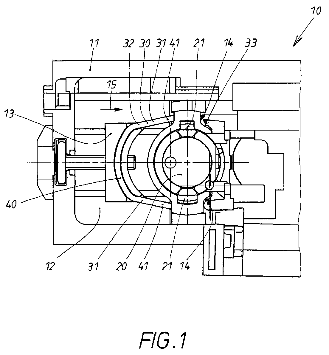
- the actuating device 10 shown in FIG. 1 serves for the actuation of Doors and / or flaps, in particular on a motor vehicle.
- the device 10 has a carrier 11, which is attachable to the door, and an in an opening 12 in the carrier 11 plug-in tower 20, either via a Lock cylinder or disguise dummy has.
- On the carrier 11 is a Locking element 30 is arranged, which in this embodiment as in approximately U-shaped bracket 40 is formed, which has two arms 31.
- the U-shaped bracket 40 is disposed on a carriage 13 which is in the carrier 11 is slidably guided.
- the arms 31 are flexible, in Unlocking position spring loaded by itself.
- the locking element 30 is in the unlocked position, so that the tower 20 is inserted and can be pulled out.
- the carrier 11 has control surfaces 14, while at the arms 31 counter-control surfaces 34 are formed, the one Spreading the legs 41 of the U-shaped bracket 40 effect.
- the Counter-control surfaces 34 are in this embodiment to the movable ends, hereinafter called movement ends 33, the arms 31.
- the other ends of the arms 31 are fixed and attached to the carriage 13, why they are referred to as Festenden 32 hereinafter.
- the locking element 30 with the arms 31 is on the back of the Carrier 11, which faces the inside of the door, arranged. Will now trying to pull the tower 20 by force, so take not only the Arms 31, but also the carrier 11 on the extraction forces. This keeps the Tower 20 was also very large extraction forces and can not be so forcibly remove.
- FIG. 3 and FIG. 4 again show the exemplary embodiment from FIG. 1 and FIG. 2, but this time for illustration without carrier 11. It can be seen in FIG. 4 clearly how the arms 31 at their locking points 35, the shoulders 21 of the Behind Tower 20.
- Fig. 5 shows the unlocking position, in which in a Opening 12 of the carrier 11 located tower 20 can be removed from the carrier 11 is, while Fig. 6 shows the locking position in which the tower 20 is not can be pulled out of the carrier 11.
- a slide 13 is slidably guided in the carrier 11.
- the Arms 31 of the locking element 30 are at its fixed end 32 on the carrier 11 rotatably mounted.
- guide holes 43 are formed here as slots 44, the counter control surfaces 34th mounted with the corresponding guide cams 45 of the carriage 13th located control surfaces 14 are formed as link guides 42.
- FIG. 7 A third embodiment of the invention in the locked position is shown in FIG. 7.
- the arms 31 pivot in the Entriegelungs ein, whereby the locking points 35 of the arms 31 with the shoulders 21 of the tower 20 are disengaged.
- FIG. 7 A similar embodiment in the locked position is shown in FIG.
- the control surfaces 14 also on the carriage 13, the at Moving in its direction of movement 15, the arms 31 of the Locking element 30 spreads.
- the carriage 13 in its locking position within the arms 31 of the in arranged about U-shaped bracket 40. This is his direction of movement 15 of the direction of movement of the embodiment of FIG. 7 opposite.
- Fig. 9 and Fig. 10 show the invention in a further embodiment.
- Fig. 9 shows the locking position.
- the arms 31 are also here designed as legs 41 of a U-shaped bracket 40 and engage behind their locking points 31 shoulders 21 of the tower 20.
- a carriage 13 on which the Control surfaces 14 are provided, which with the at the movement ends 33 of the Arms 31 mounted counter-control surfaces 34 cooperate to a Pivoting the arms 31 to effect.
- the Control surfaces 14 in recesses 16 of the carriage 13, in which the Moving ends 33 of the arms 31 engage.
- the recesses 16 so dimensioned that when spreading the arms 31 these still in the Recesses 16 remain engaged. Moves the carriage 13 in his Movement direction 15, so pivot the arms 31, causing you in the in Fig.
- unlocking position passes.
- boundary surfaces 17 are provided to prevent slipping out of To prevent movement ends 33 of the arms 31.
- the locking points 35 are no longer with the Shoulders 21 of the tower 20 engaged, so that this plugged easily or can be pulled out.
- FIGS. 11 to 13 show a final embodiment of the invention Invention.
- the locking member 30 includes only one arm 31, the in Locking position engages behind a 20 located on the tower shoulder 21.
- the tower 20 on its relative to the shoulder 21 diametrically opposite side on a paragraph 50, which in Locking position with a located on the carrier 11 stop 51 in Intervention comes.
- the tower 20 is transversely displaceable in the carrier 11 stored.
- the tower 20 has its plug-in direction 22 in its direction front side a slope 52, behind which the shoulder 21st located. As shown in Fig. 12, now encounters when inserting the tower 20 in Plug-in 22 of the spring-loaded arm 31 of the locking element 30th to the slope surface 52.
Landscapes
- Engineering & Computer Science (AREA)
- Mechanical Engineering (AREA)
- Lock And Its Accessories (AREA)
Abstract
Die dargestellte Betätigungsvorrichtung (10) findet für Türen und Klappen,
insbesondere an einem Kraftfahrzeug Verwendung. Sie enthält einen Träger
(11), der an der Tür befestigbar ist, einen entweder einen Schließzylinder oder
eine Verkleidungsattrappe aufweisenden Turm (20), der nachträglich in eine
Öffnung (12) des Trägers (11) einsteckbar ist und dessen Turmende von der
Außenseite der Tür zugänglich ist, sowie ein am Träger (11) angeordnetes
Verriegelungselement, welches zwischen einer den Turm (20) im Träger (11)
verriegelnden Verriegelungsstellung und einer den Turm freigebenden
Entriegelungsstellung beweglich ist. Das Verriegelungselement weist
wenigstens einen zum Turm (20) in radialer Richtung schwenkbeweglichen
Arm (31) auf, der in der Verriegelungsstellung eine Schulter (21) am Turm (20)
hintergreift, (Fig. 1).
Description
Die Erfindung bezieht sich auf eine Betätigungsvorrichtung der im Oberbegriff des Anspruches 1 genannten Art. Die so gestalteten Betätigungsvorrichtungen kommen in der Regel an Türen und Klappen insbesondere an Kraftfahrzeugen zum Einsatz. Zu solchen Vorrichtungen gehört auch ein sogenannter "Turm", der entweder einen Schließzylinder oder eine Verkleidungsattrappe aufweist und welcher normalerweise erst nach Befestigung des Trägers an der Tür in die Betätigungsvorrichtung eingebaut wird. Hierbei wird der Turm von der Türaußenseite aus in eine Öffnung des Trägers eingesteckt und durch ein am Träger verschiebbar geführtes Verriegelungselement von einer Entriegelungsstellung, bei der der Turm eingesteckt oder herausgezogen werden kann, in eine Verriegelungsstellung, bei der der Turm im Träger verriegelt wird, überführt. Wird der Turm aus dem Träger gewaltsam herausgezogen, so können Unbefugte Zugriff auf das Fahrzeuginnere erhalten, was für die an die Diebstahlsicherheit gestellten Anforderungen unbefriedigend ist.The invention relates to an actuating device in the preamble of claim 1 type. The so-designed actuators usually come on doors and flaps especially on motor vehicles for use. Such devices also include a so-called "tower", which has either a lock cylinder or a dummy fairing and which usually only after attachment of the carrier to the door in the Actuator is installed. Here, the tower of the Door outside plugged into an opening in the carrier and through an am Carrier slidably guided locking element of a Unlocking position in which the tower is inserted or withdrawn can, in a locking position, in which the tower is locked in the carrier, transferred. If the tower is forcibly pulled out of the carrier, so can Unauthorized access to the vehicle interior, what for the at the Theft security requirements are unsatisfactory.
Bei der aus der EP 1 026 351 A1 bekannten Betätigungsvorrichtung dieser Art wird ein plattenförmiger Schieber mit einem Ausschnitt versehen, wodurch dieser eine U-Form erhält. Dieser U-Schieber ist mit seinen Schenkeln in seitlichen Führungsschienen des Trägers verschieblich. Am die beiden U-Schenkel verbindenden Steg ist eine Gewindeaufnahme für eine Stellschraube vorgesehen, die mit ihrem Schraubenkopf ins Bügelinnere weist, während das zur Betätigung der Schraube dienende Betätigungsende seitlich aus dem Träger herausragt. Dieses Betätigungsende der Stellschraube ist durch eine seitliche Öffnung im Falzbereich der Tür betätigbar. Beim Betätigen der Stellschraube stößt der Schraubenkopf an eine Seitenwand des in eine Öffnung des Trägers eingesteckten Turms und bewegt beim weiteren Verschrauben den U-förmigen Schieber in Richtung auf den Türfalz. Dabei fahren am Ende der beiden U-Schenkel sitzende Nasen in entsprechende Aussparungen des Turms, wodurch ein Herausziehen des Turms aus dem Träger verhindert werden soll. Die Ausreißfestigkeit des Turms über den zwischen den Nasen des U-Schiebers und dem Schraubenkopf der Stellschraube eingespannten Turm ist jedoch unbefriedigend, da die Nasen und die Aussparungen die bei einem gewaltsamen Ausreißen des Turmes zustande kommenden Kräfte nicht aufnehmen können. Den Anforderungen an die Diebstahlsicherheit ist somit durch diese Vorrichtung nicht genüge getan.In the known from EP 1 026 351 A1 actuator of this type a plate-shaped slider is provided with a cutout, whereby this one gets a U-shape. This U-slider is with his thighs in lateral guide rails of the carrier slidably. At the two U-thighs connecting web is a threaded receptacle for a set screw provided, which points with her screw head inside the temple, while the for actuating the screw serving end side of the carrier protrudes. This operating end of the screw is by a lateral Opening can be actuated in the rebate area of the door. When operating the adjusting screw the screw head abuts a side wall of the in an opening of the carrier plugged tower and moves the further screwing the U-shaped Slider towards the door fold. It goes at the end of the two U-legs sitting noses in corresponding recesses of the tower, causing a withdrawal of the tower is to be prevented from the carrier. The Tear resistance of the tower over the between the noses of the U-slider and however, the tower clamped to the screw head of the set screw is unsatisfactory, since the noses and the recesses at a violent Ripping out of the tower can not absorb existing forces. The requirements for theft security is thus by this Device not enough done.
Aus der DE 199 40 809 A1 ist eine Befestigungsanordnung für einen Schließzylinder an einem Schmutzfänger eines Kraftrads bekannt, bei der der Schließzylinder in ein Loch einer als Verriegelungselement wirkenden Blattfederplatte einsetzbar ist. An der Blattfederplatte ist mindestens eine elastisch verbiegbare Federzunge angeformt, deren Federzungen-Ende in eine Rechtecknut im Umfangsbereich des Schließzylinders einschnappt, wenn man den Zylinder von außen in das Loch der Blattfederplatte einsteckt. Dann liegt die Verriegelungsstellung der Blattfeder vor. Die Blattfedern sind aber nicht ohne Weiteres in eine Entriegelungsstellung überführbar, wenn berechtigte Personen den Schließzylinder aus dem Kraftrad ausbauen oder austauschen wollen.From DE 199 40 809 A1 a fastening arrangement for a Lock cylinder on a mudflap of a motorcycle known in the Lock cylinder in a hole acting as a locking element Leaf spring plate is used. At the leaf spring plate is at least one elastically bendable spring tongue molded, the spring tongue end in a Rechtecknut in the peripheral region of the lock cylinder snaps when you the cylinder is inserted from the outside into the hole of the leaf spring plate. Then it lies the locking position of the leaf spring before. The leaf springs are not readily convertible into an unlocked position, if authorized Persons remove or replace the lock cylinder from the motorcycle want.
Der Erfindung liegt die Aufgabe zugrunde, eine zuverlässige Betätigungsvorrichtung der im Oberbegriff des Anspruches 1 genannten Art zu entwickeln, die sich durch eine hohe Ausreißfestigkeit des Turms aus der fertig montierten Vorrichtung, und somit durch eine erhöhte Diebstahlsicherheit auszeichnet. Dies wird erfindungsgemäß durch die im Anspruch 1 genannten Maßnahmen erreicht, denen folgende besondere Bedeutung zukommt. The invention is based on the object, a reliable Actuator referred to in the preamble of claim 1 Art develop, characterized by a high tear resistance of the tower from the finished mounted device, and thus by an increased theft security distinguished. This is inventively mentioned in the claim 1 Measures which are of particular importance.
Das in der Betätigungsvorrichtung befindliche Verriegelungselement weist wenigstens einen zum Turm in radialer Richtung schwenkbeweglichen Arm auf. Befindet sich die Vorrichtung in Verriegelungsstellung, so hintergreift der Arm eine Schulter am Turm. Bei dem Versuch den Turm gewaltsam herauszuziehen um unbefugt ins Fahrzeuginnere zu gelangen, stützt sich die verriegelungswirksame Stelle am Arm an der Schulter des Turms ab und nimmt die Ausreißkräfte auf. Die erfindungsgemäße Vorrichtung kann so auch hohen Ausziehkräften standhalten. Die radiale Schwenkbeweglichkeit des Arms ermöglicht ein besonders einfaches Ver- und Entriegeln des Turmes, wobei die Vorrichtung wenig Platz benötigt.The locking element located in the actuating device has at least one pivotable arm to the tower in the radial direction. The device is in locking position, so engages behind the arm a shoulder at the tower. In an attempt to forcibly pull out the tower to get into the vehicle without authorization, the interlocking point on the arm at the shoulder of the tower and takes off the pull-out forces on. The device according to the invention can thus also high Withstand extraction forces. The radial pivoting mobility of the arm allows a particularly easy locking and unlocking of the tower, the Device requires little space.
Weitere Vorteile und Ausführungen der Erfindung ergeben sich aus den Unteransprüchen, sowie der nachfolgenden Beschreibung und den Zeichnungen. In den Zeichnungen ist der Erfindungsgegenstand in mehreren Ausführungsbeispielen dargestellt. Es zeigen:
- Fig. 1
- eine erfindungsgemäße Betätigungsvorrichtung in einer ersten Ausführungsform mit Träger in Entriegelungsstellung
- Fig. 2
- die Betätigungsvorrichtung gemäß Fig. 1 in Verriegelungsstellung
- Fig. 3
- die Betätigungsvorrichtung gemäß Fig. 1 ohne Träger
- Fig. 4
- die Betätigungsvorrichtung gemäß Fig. 3 in Verriegelungsstellung
- Fig. 5
- eine erfindungsgemäße Betätigungsvorrichtung in einer zweiten Ausführungsform in Entriegelungsstellung
- Fig. 6
- die Betätigungsvorrichtung gemäß Fig. 5 in Verriegelungsstellung
- Fig. 7
- eine erfindungsgemäße Betätigungsvorrichtung in einer dritten Ausführungsform in Verriegelungsstellung
- Fig. 8
- eine erfindungsgemäße Betätigungsvorrichtung in einer vierten Ausführungsform in Verriegelungsstellung
- Fig. 9
- eine erfindungsgemäße Betätigungsvorrichtung in einer fünften Ausführungsform in Verriegelungsstellung
- Fig. 10
- die Betätigungsvorrichtung gemäß Fig. 9 in Entriegelungsstellung
- Fig. 11
- eine erfindungsgemäße Betätigungsvorrichtung in einer sechsten Ausführungsform in Verriegelungsstellung
- Fig. 12
- die Betätigungsvorrichtung gemäß Schnitt XIII-XIII in Fig. 11, jedoch während des Einsteckens des Turmes
- Fig. 13
- die Betätigungsvorrichtung gemäß Schnitt XIII-XIII in Fig. 11, in Verriegelungsstellung
- Fig. 1
- an actuating device according to the invention in a first embodiment with carrier in unlocked position
- Fig. 2
- the actuator of FIG. 1 in the locked position
- Fig. 3
- the actuator of FIG. 1 without a carrier
- Fig. 4
- the actuator of FIG. 3 in the locked position
- Fig. 5
- an actuating device according to the invention in a second embodiment in the unlocked position
- Fig. 6
- the actuator of FIG. 5 in the locked position
- Fig. 7
- an actuating device according to the invention in a third embodiment in the locked position
- Fig. 8
- an actuating device according to the invention in a fourth embodiment in the locked position
- Fig. 9
- an actuating device according to the invention in a fifth embodiment in the locking position
- Fig. 10
- the actuator of FIG. 9 in unlocked position
- Fig. 11
- an actuating device according to the invention in a sixth embodiment in the locked position
- Fig. 12
- the actuator according to section XIII-XIII in Fig. 11, but during the insertion of the tower
- Fig. 13
- the actuator according to section XIII-XIII in Fig. 11, in the locked position
Die in Fig. 1 dargestellte Betätigungsvorrichtung 10 dient der Betätigung von
Türen und/oder Klappen insbesondere an einem Kraftfahrzeug. Die Vorrichtung
10 verfügt über einen Träger 11, der an der Tür befestigbar ist, und einen in
eine Öffnung 12 im Träger 11 einsteckbaren Turm 20, der entweder über einen
Schließzylinder oder eine Verkleidungsattrappe verfügt. Am Träger 11 ist ein
Verriegelungselement 30 angeordnet, welches in diesem Ausführungsbeispiel
als in etwa U-förmiger Bügel 40 ausgebildet ist, der über zwei Arme 31 verfügt.
Der U-förmige Bügel 40 ist auf einem Schlitten 13 angeordnet, der im Träger
11 verschieblich geführt ist. Die Arme 31 sind biegsam, in
Entriegelungsstellung durch sich selbst federbelastet. Das Verriegelungselement
30 befindet sich in Entriegelungsstellung, so dass der Turm 20 eingesteckt und
herausgezogen werden kann. Hierbei verfügt der Träger 11 über Steuerflächen
14, während an den Armen 31 Gegensteuerflächen 34 ausgebildet sind, die eine
Spreizung der Schenkel 41 des U-förmigen Bügels 40 bewirken. Die
Gegensteuerflächen 34 befinden sich in diesem Ausführungsbeispiel an den
beweglichen Enden, im Weiteren Bewegungsenden 33 genannt, der Arme 31.
Die anderen Enden der Arme 31 sind fest und an dem Schlitten 13 befestigt,
weshalb sie im Weiteren als Festenden 32 bezeichnet werden. The
Verschiebt man nun den Schlitten 13 in seiner Bewegungsrichtung 15, so fährt
das Verriegelungselement 30 in seine Verriegelungsstellung, welche aus Fig. 2
ersichtlich ist. Die am Träger 11 angeordneten Steuerflächen 14 bewirken bei
Verschiebung des Schlittens 13 über die Gegensteuerflächen 34 eine
Verschwenkung der Arme 31 radial zum Turm 20. In Verriegelungsstellung
hintergreifen die Arme 31 des Verriegelungselementes 30 zwei voneinander
wegweisende Schultern 21 am Turm 20. Der Turm 20 ist nun verriegelt und
kann nicht mehr aus dem Träger 11 herausgezogen werden.If you now move the
Das Verriegelungselement 30 mit den Armen 31 ist auf der Rückseite des
Trägers 11, welche der Innenseite der Tür zugewandt ist, angeordnet. Wird nun
versucht den Turm 20 gewaltsam herauszuziehen, so nehmen nicht nur die
Arme 31, sondern auch der Träger 11 die Ausziehkräfte auf. Hierdurch hält der
Turm 20 auch sehr großen Ausziehkräften stand und lässt sich so nicht
gewaltsam entfernen.The locking
Fig. 3 und Fig. 4 zeigen nochmals das Ausführungsbeispiel aus Fig. 1 und Fig.
2, diesmal jedoch zur Veranschaulichung ohne Träger 11. Man sieht aus Fig. 4
deutlich, wie die Arme 31 an ihren Verriegelungsstellen 35 die Schultern 21 des
Turms 20 hintergreifen.FIG. 3 and FIG. 4 again show the exemplary embodiment from FIG. 1 and FIG.
2, but this time for illustration without
In Fig. 5 und Fig. 6 ist ein zweites Ausführungsbeispiel der Erfindung
dargestellt. Fig. 5 zeigt dabei die Entriegelungsstellung, in der der in einer
Öffnung 12 des Trägers 11 befindliche Turm 20 aus dem Träger 11 entnehmbar
ist, während Fig. 6 die Verriegelungsstellung zeigt, in der der Turm 20 nicht
aus dem Träger 11 herausgezogen werden kann. Auch bei dieser
Ausführungsform ist im Träger 11 ein Schlitten 13 verschieblich geführt. Die
Arme 31 des Verriegelungselementes 30 sind an ihrem Festende 32 am Träger
11 drehbar befestigt. An ihrem Bewegungsende 33 sind in Führungslöchern 43,
die hier als Langlöcher 44 ausgebildet sind, die Gegensteuerflächen 34
angebracht, die mit entsprechenden an Führungsnocken 45 des Schlittens 13
befindlichen Steuerflächen 14 als Kulissenführungen 42 ausgebildet sind. Beim
Verfahren des Schlittens 13 in die auf Fig. 5 gezeigte Bewegungsrichtung 15
verschieben sich die Führungsnocken 45 in den Führungslöchern 43 und
verschwenken so die beiden Arme 31 des Verriegelungselementes 30, wodurch
die in Fig. 6 dargestellte Position erreicht wird. In dieser Verriegelungsstellung
hintergreifen wieder die Verriegelungsstellen 35 der Arme 31
korrespondierende Schultern 21 am Turm 20.In Fig. 5 and Fig. 6 is a second embodiment of the invention
shown. Fig. 5 shows the unlocking position, in which in a
Eine dritte Ausführungsform der Erfindung in Verriegelungsstellung zeigt Fig.
7. Hier befinden sich die Steuerflächen 14 am Schlitten 13, der hierdurch beim
Verschieben in seine Bewegungsrichtung 15 die biegsamen Arme 31 des durch
einen in etwa U-förmigen Bügel 40 dargestellten Verriegelungselements 30
spreizt. Durch das Spreizen verschwenken die Arme 31 in die
Entriegelungsstellung, wodurch die Verriegelungsstellen 35 der Arme 31 mit
den Schultern 21 des Turmes 20 außer Eingriff gebracht werden.A third embodiment of the invention in the locked position is shown in FIG.
7. Here are the control surfaces 14 on the
Eine ähnliche Ausführungsform in Verriegelungsstellung wird in Fig. 8 gezeigt.
Hier befinden sich die Steuerflächen 14 ebenfalls am Schlitten 13, der beim
Verschieben in seine Bewegungsrichtung 15 die Arme 31 des
Verriegelungselementes 30 spreizt. Allerdings ist in dieser Ausführungsform
der Schlitten 13 in seiner Verriegelungsposition innerhalb der Arme 31 des in
etwa U-förmigen Bügels 40 angeordnet. Hierdurch ist seine Bewegungsrichtung
15 der Bewegungsrichtung der Ausführungsform aus Fig. 7 entgegengesetzt.A similar embodiment in the locked position is shown in FIG.
Here are the
Fig. 9 und Fig. 10 zeigen die Erfindung in einem weiteren Ausführungsbeispiel.
Hierbei zeigt Fig. 9 die Verriegelungsstellung. Die Arme 31 sind hier ebenfalls
als Schenkel 41 eines U-förmigen Bügels 40 ausgeführt und hintergreifen an
ihren Verriegelungsstellen 31 Schultern 21 des Turms 20. Weiterhin verfügt
auch diese Ausführungsform über einen Schlitten 13, an welchem die
Steuerflächen 14 vorgesehen sind, die mit den an den Bewegungsenden 33 der
Arme 31 angebrachten Gegensteuerflächen 34 zusammenwirken, um ein
Verschwenken der Arme 31 zu bewirken. Hierbei befinden sich die
Steuerflächen 14 in Ausnehmungen 16 des Schlittens 13, in welche die
Bewegungsenden 33 der Arme 31 eingreifen. Hierbei sind die Ausnehmungen
16 so bemessen, dass beim Spreizen der Arme 31 diese immer noch in den
Ausnehmungen 16 in Eingriff bleiben. Verschiebt man den Schlitten 13 in seine
Bewegungsrichtung 15, so verschwenken die Arme 31, wodurch man in die in
Fig. 10 gezeigte Entriegelungsstellung gelangt. Bei dieser Ausführungsform
sind Begrenzungsflächen 17 vorgesehen, um ein Herausrutschen der
Bewegungsenden 33 der Arme 31 zu verhindern. In der so erreichten
Entriegelungsposition sind die Verriegelungsstellen 35 nicht mehr mit den
Schultern 21 des Turmes 20 in Eingriff, so dass dieser problemlos eingesteckt
oder herausgezogen werden kann.Fig. 9 and Fig. 10 show the invention in a further embodiment.
Here, Fig. 9 shows the locking position. The
Die Fig. 11 bis 13 zeigen nunmehr ein letztes Ausführungsbeispiel der
Erfindung. Hier enthält das Verriegelungselement 30 nur einen Arm 31, der in
Verriegelungsstellung eine am Turm 20 befindliche Schulter 21 hintergreift.
Weiterhin weist der Turm 20 auf seiner bezüglich der Schulter 21 diametral
gegenüberliegenden Seite einen Absatz 50 auf, welcher in
Verriegelungsstellung mit einem am Träger 11 befindlichen Anschlag 51 in
Eingriff kommt. Hierzu ist der Turm 20 im Träger 11 querverschieblich
gelagert. Des Weiteren weist der Turm 20 an seiner in Einsteckrichtung 22
vorderen Seite eine Neigungsfläche 52 auf, hinter welcher sich die Schulter 21
befindet. Wie in Fig. 12 gezeigt, stößt nun beim Einstecken des Turms 20 in
Einsteckrichtung 22 der federbelastete Arm 31 des Verriegelungselementes 30
an die Neigungsfläche 52. Durch weiteres Einschieben des Turms 20 wird der
Arm 31 entgegen seiner Federbelastung an der Neigungsfläche 52 vom Turm 21
weg in Richtung der Schulter 21 gedrückt. Hat der Turm 20 seine
Einsteckposition erreicht, so schnappt der Arm 31 hinter die Schulter 21. Durch
die Federbelastung des Arms 31 wird der Turm 20 im Träger 11 in Richtung
seiner Querverschiebung 53 verschoben, so dass der Absatz 50 des Turms 20
den Anschlag 51 des Trägers 11 hintergreift und so die Betätigungsvorrichtung
10 ihre Verriegelungsstellung erreicht, wie in Fig. 13 dargestellt.FIGS. 11 to 13 show a final embodiment of the invention
Invention. Here, the locking
Die hier dargestellten Ausführungsformen stellen lediglich beispielsweise Verwirklichungen der Erfindung dar. Diese ist nicht darauf beschränkt, sondern es sind vielmehr verschiedenste Abwandlungen und Ausführungen möglich. Es sind beispielsweise noch weitere Ausgestaltungen der Arme denkbar, die verschieden ausgeführte Schultern im Turm hintergreifen. Auch sind weitere Methoden des Verschwenkens des Arms zwischen Verriegelungs- und Entriegelungsstellung möglich. Auch der Schlitten kann verschiedenste Ausgestaltungen haben. Schließlich sind auch noch weitere Ausführungen der Steuerflächen und Gegensteuerflächen denkbar, die dann entsprechend ihrer Ausgestaltung zusammen wirken. The embodiments shown here are merely examples Realizations of the invention. This is not limited thereto, but Rather, various modifications and designs are possible. It For example, further embodiments of the arms are conceivable, the variously executed shoulders in the tower behind. Also are more Methods of pivoting the arm between lock and unlock Unlocking position possible. The sled can also be very different Have configurations. Finally, there are other versions of the Control surfaces and counter-control surfaces conceivable, which then according to their Design work together.
- 1010
- Betätigungsvorrichtungactuator
- 1111
- Trägercarrier
- 1212
- Öffnung in 11Opening in 11
- 1313
- Schlittencarriage
- 1414
- Steuerflächecontrol surface
- 1515
- Bewegungsrichtung von 13Movement direction of 13
- 1616
- Ausnehmung in 13Recess in 13
- 2020
- Turmtower
- 2121
- Schulter an 20Shoulder at 20
- 2222
- Einsteckrichtung von 20Insertion direction of 20
- 3030
- Verriegelungselementlocking element
- 3131
- Armpoor
- 3232
- Festende von 31Festive of 31
- 3333
- Bewegungsende von 31Movement end of 31
- 3434
- GegensteuerflächeAgainst control surface
- 3535
- Verriegelungsstelle an 31Locking point at 31
- 4040
- U-förmiger BügelU-shaped bracket
- 4141
- Schenkel von 40Thighs of 40
- 4242
- Kulissenführunglink guide
- 4343
- Führungslochhole
- 4444
- LanglochLong hole
- 4545
- Führungsnockenguide cam
- 5050
- Absatzparagraph
- 5151
- Anschlagattack
- 5252
- Neigungsflächesloping surface
- 5353
- Querverschiebung von 20Transverse shift of 20
Claims (15)
mit einem Träger (11), der an der Tür befestigbar ist,
mit einem entweder einen Schließzylinder oder eine Verkleidungsattrappe aufweisenden Turm (20),
der nachträglich in eine Öffnung (12) des Trägers (11) einsteckbar ist und dessen Turmende von der Außenseite der Tür zugänglich ist,
mit einem am Träger (11) angeordneten Verriegelungselement, das zwischen einer den Turm (20) im Träger (11) verriegelnden Verriegelungsstellung und einer den Turm (20) freigebenden Entriegelungsstellung beweglich ist,
dadurch gekennzeichnet, dass das Verriegelungselement (30) wenigstens einen zum Turm (20) in radialer Richtung schwenkbeweglichen Arm (31) aufweist,
und dass der Arm (31) in der Verriegelungsstellung eine Schulter (21) am Turm (20) hintergreift.Actuating device (10) for doors or flaps, in particular on a motor vehicle,
with a support (11) which can be fastened to the door,
with a tower (20) having either a lock cylinder or a fairing dummy,
which is subsequently inserted into an opening (12) of the carrier (11) and whose turret end is accessible from the outside of the door,
with a locking element arranged on the carrier (11), which is movable between a locking position locking the tower (20) in the carrier (11) and an unlocking position releasing the tower (20),
characterized in that the locking element (30) has at least one arm (31) which can be pivoted in the radial direction to the tower (20),
and that the arm (31) in the locked position engages behind a shoulder (21) on the tower (20).
und in Verriegelungsstellung zwei voneinander wegweisende Schultern (21) am Turm (20) hintergreifen.Actuating device (10) according to any one of claims 1 or 2, characterized in that the locking element (30) comprises two expandable and / or compressible arms (31) which are movable in mirror image at the transition between the locking and unlocking position
and in the locking position, two mutually pioneering shoulders (21) engage behind the tower (20).
dass der Arm (31) bzw. die Arme (31) mit ihrem ersten, festen Ende (Festende) (32) am Schlitten (13) befestigt sind,
und dass sich eine Steuerfläche (14) am Träger (11) und eine Gegensteuerfläche (34) am Arm (31) befinden, die das zweite, bewegliche Ende (Bewegungsende) (33) bei der Bewegung (15) des Schlittens (13) zwischen der Verriegelungs- und der Entriegelungsstellung verschwenken.Actuating device (10) according to one of claims 1 to 6, characterized in that a carriage (13) on the support (11) is guided longitudinally,
the arm (31) or the arms (31) are fastened to the carriage (13) with their first, fixed end (fixed end) (32),
and that a control surface (14) on the support (11) and a counter-control surface (34) on the arm (31), the second, movable end (movement end) (33) during the movement (15) of the carriage (13) between pivot the locking and unlocking.
dass der Arm (31) bzw. die Arme (31) mit ihrem ersten, festen Ende (Festende) (32) am Träger (11) befestigt sind,
und dass sich eine Steuerfläche (14) am Schlitten (13) und eine Gegensteuerfläche (34) am Arm (31) befinden, die das zweite, bewegliche Ende (Bewegungsende) (33) bei der Bewegung (15) des Schlittens (13) zwischen der Entriegelungs- und der Verriegelungsstellung verschwenken.Actuating device (10) according to one of claims 1 to 6, characterized in that a carriage (13) on the support (11) is guided longitudinally,
the arm (31) or the arms (31) are fastened to the carrier (11) with their first, fixed end (fixed end) (32),
and that a control surface (14) on the carriage (13) and a counter-control surface (34) on the arm (31) are the second, movable end (movement end) (33) during the movement (15) of the carriage (13) between pivot the unlocking and the locking position.
und dass die Verriegelungsstelle (35) des Arms (31) bzw. Hebels vom Bewegungsende (33) beabstandet ist.Actuating device (10) according to claim 12, characterized in that the slotted guide (42) in the region of the movement end (33) of the arm (31) or lever is arranged
and that the locking point (35) of the arm (31) or lever from the end of movement (33) is spaced.
dass der Turm (20) auf seiner bezüglich der Schulter (21) im Wesentlichen gegenüberliegenden Seite einen Absatz (50) aufweist,
dass der Turm (20) im Träger (11) in Richtung des Absatzes (50) quer verschieblich ist
und dass in der Verriegelungsstellung des Turmes (20) der Absatz (50) einen Anschlag (51) des Trägers (11) hintergreift.Actuating device (10) according to one of claims 1 to 13, characterized in that the locking element (30) has only one arm (31) or lever,
the tower (20) has a shoulder (50) on its side substantially opposite the shoulder (21),
in that the tower (20) in the carrier (11) is transversely displaceable in the direction of the shoulder (50)
and that in the locking position of the tower (20) of the shoulder (50) engages behind a stop (51) of the carrier (11).
dass beim Einstecken (22) des Turms (20) die Neigungsfläche (52) gegen den Arm (31) bzw. Hebel stößt,
wobei der in Richtung seiner Verriegelungsstellung federbelastete Arm (31) bzw. Hebel von der Neigungsfläche (52) gegen seine Federbelastung vom Turm (20) weggedrückt wird bis der Arm (31) bzw. Hebel hinter die Schulter (21) schnappt,
und dass der Arm (31) bzw. Hebel durch seine Federbelastung die Querverschiebung (53) des Turmes (20) in Einsteckposition bewirkt.Actuating device (10) according to claim 14, characterized in that the tower (20) has a sloping surface (52), behind which the shoulder (21) is located,
that upon insertion (22) of the tower (20) the inclination surface (52) abuts against the arm (31) or lever,
wherein the spring-loaded in the direction of its locking position arm (31) or lever of the inclination surface (52) is pressed against its spring load from the tower (20) until the arm (31) or lever snaps behind the shoulder (21),
and that the arm (31) or lever causes by its spring load, the transverse displacement (53) of the tower (20) in the insertion position.
Applications Claiming Priority (2)
| Application Number | Priority Date | Filing Date | Title |
|---|---|---|---|
| DE102004007083 | 2004-02-13 | ||
| DE200410007083 DE102004007083B3 (en) | 2004-02-13 | 2004-02-13 | Actuating device for doors or tailgates of motor vehicles comprises a locking element having an arm pivoting towards a spar in the radial direction |
Publications (3)
| Publication Number | Publication Date |
|---|---|
| EP1580352A2 true EP1580352A2 (en) | 2005-09-28 |
| EP1580352A3 EP1580352A3 (en) | 2008-01-23 |
| EP1580352B1 EP1580352B1 (en) | 2009-04-08 |
Family
ID=34813330
Family Applications (1)
| Application Number | Title | Priority Date | Filing Date |
|---|---|---|---|
| EP20050002736 Ceased EP1580352B1 (en) | 2004-02-13 | 2005-02-10 | Actuating device for doors or lids |
Country Status (2)
| Country | Link |
|---|---|
| EP (1) | EP1580352B1 (en) |
| DE (2) | DE102004007083B3 (en) |
Families Citing this family (5)
| Publication number | Priority date | Publication date | Assignee | Title |
|---|---|---|---|---|
| US8347676B2 (en) * | 2004-11-30 | 2013-01-08 | Valeo Sistemas Automotivos Ltda. | Constructive improvement to an anti-theft lock device applied to automobile trunks |
| FR2915227B1 (en) * | 2007-04-17 | 2010-10-22 | Coutier Moulage Gen Ind | EXTERNAL DOOR HANDLE ASSEMBLY FOR A MOTOR VEHICLE. |
| DE102011000224A1 (en) * | 2010-10-18 | 2012-04-19 | Huf Hülsbeck & Fürst Gmbh & Co. Kg | Device for fastening an essential component |
| US10196842B2 (en) | 2014-06-20 | 2019-02-05 | Huf North America Automotive Parts Manufacturing Corp. | Retention mechanism for insertion member in vehicular door handle assembly |
| EP2977532B1 (en) * | 2014-07-22 | 2018-05-09 | Volkswagen Aktiengesellschaft | External handle system for a vehicle door |
Family Cites Families (4)
| Publication number | Priority date | Publication date | Assignee | Title |
|---|---|---|---|---|
| US5636540A (en) * | 1993-12-20 | 1997-06-10 | Fort Lock Corporation | Lock clip |
| DE4415154A1 (en) * | 1994-05-02 | 1995-11-09 | Valeo Deutschland Gmbh & Co | Device for fastening a part, in particular a door handle |
| JP4073553B2 (en) * | 1998-09-02 | 2008-04-09 | 本田技研工業株式会社 | Key cylinder mounting structure |
| FR2789428B1 (en) * | 1999-02-05 | 2001-04-13 | Valeo Securite Habitacle | MOTOR VEHICLE OPENING HANDLE COMPRISING IMPROVED MEANS FOR LOCKING AN EXTERNAL ELEMENT |
-
2004
- 2004-02-13 DE DE200410007083 patent/DE102004007083B3/en not_active Expired - Fee Related
-
2005
- 2005-02-10 EP EP20050002736 patent/EP1580352B1/en not_active Ceased
- 2005-02-10 DE DE200550007023 patent/DE502005007023D1/en not_active Expired - Lifetime
Also Published As
| Publication number | Publication date |
|---|---|
| EP1580352A3 (en) | 2008-01-23 |
| DE502005007023D1 (en) | 2009-05-20 |
| DE102004007083B3 (en) | 2005-09-01 |
| EP1580352B1 (en) | 2009-04-08 |
Similar Documents
| Publication | Publication Date | Title |
|---|---|---|
| DE102013003956B4 (en) | Safety device, crash-active front hood | |
| EP2267256B1 (en) | Padlock | |
| EP2562338B1 (en) | Door handle assembly of a motor vehicle | |
| DE102007035116A1 (en) | Jointed bar lock | |
| DE102007035491A1 (en) | Tank flap unit | |
| DE102004001894B4 (en) | Actuation device for doors or flaps on vehicles | |
| DE112007000324T5 (en) | Door entrance lock | |
| EP1606136B1 (en) | Device for connecting a vehicle seat to a vehicle floor | |
| DE102007034556A1 (en) | Locking device for the front flap of a motor vehicle | |
| DE102006000619B4 (en) | Spring-loaded pawl lock with automatic reset | |
| DE10335311B4 (en) | Steering lock device | |
| EP2627542B1 (en) | Device for moving a locking member | |
| DE102004007083B3 (en) | Actuating device for doors or tailgates of motor vehicles comprises a locking element having an arm pivoting towards a spar in the radial direction | |
| DE102009030033A1 (en) | Brake disc lock with an oblique locking pin | |
| DE4112405A1 (en) | SEAT COUPLING KEYWORD: ONE-HANDED HANDLE | |
| DE202007016091U1 (en) | Espagnolette | |
| DE102018131779A1 (en) | Locking device | |
| DE102013112124A1 (en) | Steering wheel lock for a steering column for a motor vehicle | |
| DE102013103898A1 (en) | Locking device for sliding doors and locking device for sliding doors | |
| DE102020104949A1 (en) | Lever for manually unlocking a seat track assembly | |
| DE9104766U1 (en) | Anti-panic door lock | |
| DE10156632C1 (en) | Plug-type door lock has sliding bolt connected to spring and cylinder lock and has bolt stop plate with profiled slit engaging fixed pin | |
| DE10318707A1 (en) | interlock | |
| DE102023203715A1 (en) | safety system and motor vehicle | |
| DE19752252A1 (en) | Closure arrangement for motor vehicles |
Legal Events
| Date | Code | Title | Description |
|---|---|---|---|
| PUAI | Public reference made under article 153(3) epc to a published international application that has entered the european phase |
Free format text: ORIGINAL CODE: 0009012 |
|
| AK | Designated contracting states |
Kind code of ref document: A2 Designated state(s): AT BE BG CH CY CZ DE DK EE ES FI FR GB GR HU IE IS IT LI LT LU MC NL PL PT RO SE SI SK TR |
|
| AX | Request for extension of the european patent |
Extension state: AL BA HR LV MK YU |
|
| PUAL | Search report despatched |
Free format text: ORIGINAL CODE: 0009013 |
|
| AK | Designated contracting states |
Kind code of ref document: A3 Designated state(s): AT BE BG CH CY CZ DE DK EE ES FI FR GB GR HU IE IS IT LI LT LU MC NL PL PT RO SE SI SK TR |
|
| AX | Request for extension of the european patent |
Extension state: AL BA HR LV MK YU |
|
| RIC1 | Information provided on ipc code assigned before grant |
Ipc: E05B 65/20 20060101ALI20071220BHEP Ipc: E05B 65/12 20060101ALI20071220BHEP Ipc: E05B 3/00 20060101AFI20050805BHEP |
|
| 17P | Request for examination filed |
Effective date: 20080515 |
|
| AKX | Designation fees paid |
Designated state(s): DE |
|
| GRAP | Despatch of communication of intention to grant a patent |
Free format text: ORIGINAL CODE: EPIDOSNIGR1 |
|
| GRAS | Grant fee paid |
Free format text: ORIGINAL CODE: EPIDOSNIGR3 |
|
| GRAA | (expected) grant |
Free format text: ORIGINAL CODE: 0009210 |
|
| AK | Designated contracting states |
Kind code of ref document: B1 Designated state(s): DE |
|
| REF | Corresponds to: |
Ref document number: 502005007023 Country of ref document: DE Date of ref document: 20090520 Kind code of ref document: P |
|
| PLBE | No opposition filed within time limit |
Free format text: ORIGINAL CODE: 0009261 |
|
| STAA | Information on the status of an ep patent application or granted ep patent |
Free format text: STATUS: NO OPPOSITION FILED WITHIN TIME LIMIT |
|
| 26N | No opposition filed |
Effective date: 20100111 |
|
| PGFP | Annual fee paid to national office [announced via postgrant information from national office to epo] |
Ref country code: DE Payment date: 20210126 Year of fee payment: 17 |
|
| REG | Reference to a national code |
Ref country code: DE Ref legal event code: R119 Ref document number: 502005007023 Country of ref document: DE |
|
| PG25 | Lapsed in a contracting state [announced via postgrant information from national office to epo] |
Ref country code: DE Free format text: LAPSE BECAUSE OF NON-PAYMENT OF DUE FEES Effective date: 20220901 |