EP1580332A2 - Construction machine - Google Patents
Construction machine Download PDFInfo
- Publication number
- EP1580332A2 EP1580332A2 EP05102172A EP05102172A EP1580332A2 EP 1580332 A2 EP1580332 A2 EP 1580332A2 EP 05102172 A EP05102172 A EP 05102172A EP 05102172 A EP05102172 A EP 05102172A EP 1580332 A2 EP1580332 A2 EP 1580332A2
- Authority
- EP
- European Patent Office
- Prior art keywords
- vertical rib
- work equipment
- construction machine
- upper structure
- left vertical
- Prior art date
- Legal status (The legal status is an assumption and is not a legal conclusion. Google has not performed a legal analysis and makes no representation as to the accuracy of the status listed.)
- Withdrawn
Links
Images




Classifications
-
- E—FIXED CONSTRUCTIONS
- E02—HYDRAULIC ENGINEERING; FOUNDATIONS; SOIL SHIFTING
- E02F—DREDGING; SOIL-SHIFTING
- E02F9/00—Component parts of dredgers or soil-shifting machines, not restricted to one of the kinds covered by groups E02F3/00 - E02F7/00
- E02F9/08—Superstructures; Supports for superstructures
-
- E—FIXED CONSTRUCTIONS
- E02—HYDRAULIC ENGINEERING; FOUNDATIONS; SOIL SHIFTING
- E02F—DREDGING; SOIL-SHIFTING
- E02F9/00—Component parts of dredgers or soil-shifting machines, not restricted to one of the kinds covered by groups E02F3/00 - E02F7/00
- E02F9/08—Superstructures; Supports for superstructures
- E02F9/0808—Improving mounting or assembling, e.g. frame elements, disposition of all the components on the superstructures
- E02F9/0825—Cast frame structure
-
- B—PERFORMING OPERATIONS; TRANSPORTING
- B62—LAND VEHICLES FOR TRAVELLING OTHERWISE THAN ON RAILS
- B62D—MOTOR VEHICLES; TRAILERS
- B62D21/00—Understructures, i.e. chassis frame on which a vehicle body may be mounted
- B62D21/18—Understructures, i.e. chassis frame on which a vehicle body may be mounted characterised by the vehicle type and not provided for in groups B62D21/02 - B62D21/17
Definitions
- the present invention relates to a construction machine, and more particularly to a frame assembly that forms the base of an upper structure of a construction machine
- a backhoe 100 chiefly comprises a lower movernent device 102, an upper structure 103, and a excavation device 104 installed on the upper structure 103, as illustrated in Fig 5, which shows a right side view
- the revolving frame F that forms the base of the upper structure 103 and is provided at the bottom face thereof is equipped with a support III on which the excavation device 104 is supported on an axle in such a way as to be able to revolve in a horizontal direction, and is illustrated in Fig 6, which shows an exploded view
- this revolving frame F needs to be of a certain size, it is constructed from sheet metal, as shown in Fig 6.
- Revolving frames used in smaller-scale machines are sometimes made from cast owing to their relatively smaller size, as for example in the turning frame described in Japanese Patent Application Laid-open No 2003-20683 (corresponding to the revolving frame of Japanese Patent Application Laid-open No 2002-146834) (not illustrated).
- Fig. 4B which is a cross-section showing the connection between the parts b1 and b2
- Fig. 4B which is a cross-section showing the connection between the parts b1 and b2
- the construction machine according to Claim I of the present invention is a construction machine (I) which comprises: an undercarriage (2), an upper structure (3) rotatably mounted on a top of the undercarriage (2), and a work equipment (10) movably supported at a front of the upper structure (3), wherein within a frame assembly (Ra) that forms a base of the upper structure (3), at least the following components are produced by casting a weldable material; a work equipment support (Rb) that supports the work equipment (10); a right vertical rib (Rs1) and a left vertical rib (Rs2), a distance therebetween widening gradually as they extend backwards from the work equipment support; a bottom plate (Rt) that extends towards inside, adjoining bottom edges (Rb2, Rs11, Rs21) of the work equipment support (Rb), the right vertical rib (Rs1) and the left vertical rib (Rs2)
- the construction machine relating to Claim 2 of the present invention is the construction machine according to Claim 1, wherein within the frame assembly (Ra), a rear vertical rib (Ru) that adjoins back edges of the right vertical rib (Rs1) and the left vertical rib (Rs2) is produced by casting together with the work equipment support (Rb), the right vertical rib (Rs1), the left vertical rib (Rs2) and the bottom plate (Rt)
- the construction machine relating to Claim 3 of the present invention is the construction machine according to Claim 1, wherein the material used in the casting is cast steel
- the construction machine relating to Claim 4 of the present invention is the construction machine according to Claim 2, wherein the material used in the casting is cast steel
- a hydraulic excavator (construction machine) 1 relating to an embodiment of the present invention comprises an undercarriage 2 equipped with a track r for movement, and an upper structure 3 rotatably mounted on top of the undercarriage 2, in which the operator sits and controls operations
- the undercarriage 2 has driver wheels 5 and follower wheels 6 installed on the both ends of the track frames 4r and 4I, the track r is wound between the driver wheel 5 and the follower wheel 6.
- a blade b used for re-burying earth dug up by the bucket 10c, is arranged in such a way as to be free to move in order to carry out its designated functions.
- the upper structure 3 is provided with an operator's seat 3a on top of which the operator sits to control operations; in front of this the work equipment 10, having boom 10a and an arm 10b driven by oil pressure, and a bucket 10c mounted onto the tip of the arm 10b for use in excavation, is supported on an axle so as to be able to move up and down, and is also supported so as to be able to revolve in a horizontal direction around a support axle (not shown) provided perpendicularly on the boom fitting (work equipment support) Rb
- the workload brought about by the bucket 10c through excavation work by the bucket 10c of the work equipment 10 is transmitted via the arm 10b and the boom 10a to the boom fitting Rb that supports the work equipment 10, and various loads or a large load are applied to the boom fitting Rb.
- a counterweight w is provided in the back of the upper structure 3
- the hydraulic excavator 1 constituted as described above is moved by starting the drive-source engine, converting the energy into oil pressure by a hydraulic pump, driving the hydraulic motor to transmit the drive force to the driver wheel 5, and rotating the driver wheel 5 to cause the track r to rotate Also, various kinds of work are carried out with the use of the bucket 10c and the blade b
- An engine is stored inside the outer panel 3p below the operator's seat 3a within the upper structure 3, while the oil-pressure valves, the revolving motor that revolves the upper structure 3 in relation to the undercarriage 2, and the pipes are stored inside the lower outer panel 3p1 below the floor F of the body of the machine
- the fuel tank, the operation oil tank, and the battery, as well as a radiator and fan for cooling the engine are stored inside the outer panel 3p on the left from the front of the operator's seat 3a on the floor F of the upper structure 3
- the upper structure 3 has the revolving frame assembly (frame assembly) Ra shown in Fig 2 as its base, inside the lower outer panel 3p1
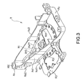
- the revolving frame assembly Ra is produced by welding a plurality of steel plate parts of certain shapes to the revolving frame R shown in Fig 3
- the revolving frame R is uniformly shaped in a cast using cast steel; at the front is the boom fitting Rb, which has an opening Rb1 running through it through which an axle passes vertically on which the work equipment 10 is supported so as to be rotatable in a horizontal direction
- the revolving frame R is constructed so as to bear a certain weight-load, since in addition to the various workloads transmitted by the work equipment 10 to the boom fitting Rb on which the work equipment 10 is supported, the revolving frame R as a whole also receives the weight of the upper structure 3 itself
- the right vertical rib Rs1 and the left vertical rib Rs2 extend From the boom fitting Rb, the distance therebetween widening as they approach the rear to form a roughly triangular shape when viewed from above; the rear vertical rib Ru is arranged so as to adjoin the back ends of the right vertical rib Rs1 and the left vertical rib Rs2
- the bottom plate Rt forms the lower face of the revolving frame R, extending inwards to adjoin the bottom edge Rb2 of the boom titling Rb, the bottom edge Rs1 of the right vertical rib Rs1, and the bottom edge Rs21 of the left vertical rib Rs2.
- the bottom plate Rt is provided with three holes Rt1 , Rt2, and Rt3, through which a swivel joint may be passed
- a valve mounting plate R3 is formed on the outer face of the bottom edge Rs1 1 of the right vertical rib Rs1, facing outwards and having an opening R31
- Fig 4A which shows a cross-section of the connecting part between the bottom plate Rt and the left vertical rib Rs2, for example, the R portion is formed without any sharp groove in the connecting part, and without any sharp corners Because of this, stress concentration is prevented in advance, and the weight-load capacity is improved.
- a sharp groove is formed in the connecting part between part b1 and part b2 in order for the parts b1 and b2 to be joined together, by welding y As a result, it is easy for stress concentration to occur.
- the revolving frame R is formed so as to be thick in places to which a heavy weight will be applied and where greater strength is required, while it is thin in places where no particular strength is necessary In this way an optimum thickness may be selected for all parts of the structure
- the revolving frame R that is the main part to which heavy loads will be applied is a light and high-strength structure
- the upper plate Ra1 is joined to the revolving frame R as shown in Fig 2 by welding it to the upper edges of the boom fitting Rb, the right vertical rib Rs1, and the left vertical rib Rs2
- welding on the upper plate Ra1 means that the upper edges of the right vertical rib Rs1 and the left vertical rib Rs2 are supported; in addition to this, because the lower edges of the right vertical rib Rs1 and the left vertical rib Rs2 are connected to the bottom plate Rt, a four-sided box shape is formed by the upper plate Ra1, the right vertical rib Rs1, the left vertical plate Rs2, and the bottom plate Rt, with the components all supporting each other, forming a high-strength structure
- a partition plate Ra2 is also welded to the revolving frame R to prevent conduction of heat from the engine, as well as a tank mounting plate Ra3 onto which the fuel tank and operation oil tank are mounted; other sheet metal parts including parts Ra4, Ra5 are also welded into position
- valves are provided in part A
- an engine is provided in part B
- the rotation motor, pipes and so on are provided in part C
- the fuel tank and operation oil tank are provided in part D
- the battery, radiator and so on are provided in part E
- the revolving frame R that is the main part of the revolving frame assembly Ra that needs to be particularly strong is uniformly formed in a cast, using the freedom of shape inherent in cast metal production to give each part its ideal thickness, while at the same time forming the R portions in the grooves and corners
- the structure of the embodiment in the example above was such that the boom fitting Rb, the right vertical rib Rs1, the left vertical rib Rs2, the rear vertical rib Ru, and the bottom plate Rt were formed integrally in a cast, it is also possible to form the boom fitting Rb, the right vertical rib Rs1, the left vertical rib Rs2, and the bottom plate Rt integrally in a cast and to make the rear vertical rib Ru from sheet metal and attach it by welding
- the right vertical rib Rs1, the left vertical rib Rs2, and the rear vertical rib Ru were described as being arranged so as to stand up in their positions
- the shape and position of the right vertical rib Rs1, the left vertical rib Rs2, and the rear vertical rib Ru is not limited to that of the present embodiment, and each rib might also be installed so as to incline in a perpendicular direction, or with secondary reinforcing ribs installed horizontally, for example.
- the shape of the boom fitting Rb is not limited to that of the present embodiment, so long as it is so structured as to movably support the work equipment 10
- the present invention may be effectively applied using a crawler dump truck, a bulldozer, or other agricultural machinery besides a hydraulic excavator, for example
Landscapes
- Engineering & Computer Science (AREA)
- Mining & Mineral Resources (AREA)
- Civil Engineering (AREA)
- General Engineering & Computer Science (AREA)
- Structural Engineering (AREA)
- Chemical & Material Sciences (AREA)
- Combustion & Propulsion (AREA)
- Transportation (AREA)
- Mechanical Engineering (AREA)
- Body Structure For Vehicles (AREA)
- Component Parts Of Construction Machinery (AREA)
Abstract
Description
Claims (4)
- A construction machine comprising an undercarriage, an upper structure rotatably mounted on a top of the undercarriage, and a work equipment movably supported at a front of the upper structure, wherein within a frame assembly that forms a base of the upper structure, at least following components are produced by casting a weldable material; a work equipment support that supports the work equipment, a right vertical rib and a left vertical rib, a distance therebetween widening gradually as they extend backwards from the work equipment support; a bottom plate that extends towards inside, adjoining bottom edges of the work equipment support, the right vertical rib and the left vertical rib
- The construction machine according to Claim 1, wherein within the frame assembly a rear vertical rib that adjoins back edges of the right vertical rib and the left vertical rib is produced by casting together with the work equipment support, the right vertical rib, the left vertical rib, and the bottom plate
- The construction machine according to Claim 1, wherein the material used in the casting is cast steel
- The construction machine according to Claim 2, wherein the material used in the casting is cast steel
Applications Claiming Priority (2)
| Application Number | Priority Date | Filing Date | Title |
|---|---|---|---|
| JP2004083392A JP2005271602A (en) | 2004-03-22 | 2004-03-22 | Construction machinery |
| JP2004083392 | 2004-03-22 |
Publications (2)
| Publication Number | Publication Date |
|---|---|
| EP1580332A2 true EP1580332A2 (en) | 2005-09-28 |
| EP1580332A3 EP1580332A3 (en) | 2006-07-05 |
Family
ID=34858382
Family Applications (1)
| Application Number | Title | Priority Date | Filing Date |
|---|---|---|---|
| EP05102172A Withdrawn EP1580332A3 (en) | 2004-03-22 | 2005-03-18 | Construction machine |
Country Status (5)
| Country | Link |
|---|---|
| US (1) | US20050204590A1 (en) |
| EP (1) | EP1580332A3 (en) |
| JP (1) | JP2005271602A (en) |
| KR (1) | KR20060043739A (en) |
| CN (1) | CN1673465A (en) |
Cited By (4)
| Publication number | Priority date | Publication date | Assignee | Title |
|---|---|---|---|---|
| EP2182121A1 (en) * | 2008-10-30 | 2010-05-05 | Kobelco Construction Machinery Co. Ltd. | Frame structure of construction machine |
| EP2302140A1 (en) * | 2009-09-29 | 2011-03-30 | Kubota Corporation | Swivel frame |
| DE102011109080A1 (en) * | 2011-07-27 | 2013-01-31 | Liebherr-Hydraulikbagger Gmbh | Revolving platform element for a construction machine |
| EP4534762A1 (en) * | 2023-10-02 | 2025-04-09 | Yanmar Holdings Co., Ltd. | Revolving frame and work machine |
Families Citing this family (9)
| Publication number | Priority date | Publication date | Assignee | Title |
|---|---|---|---|---|
| JP5066872B2 (en) * | 2006-09-08 | 2012-11-07 | 株式会社豊田自動織機 | Frame structure of counterbalance type cargo handling vehicle |
| KR100910169B1 (en) * | 2007-07-04 | 2009-07-31 | 볼보 컨스트럭션 이키프먼트 홀딩 스웨덴 에이비 | Top frame of excavator |
| JP5156294B2 (en) * | 2007-08-03 | 2013-03-06 | 株式会社小松製作所 | Construction machine mainframe and construction machine equipped with the same |
| JP5100732B2 (en) * | 2009-09-29 | 2012-12-19 | 株式会社クボタ | Swing frame of swivel work machine |
| JP5814578B2 (en) * | 2011-03-24 | 2015-11-17 | 株式会社小松製作所 | Electric work vehicle and its base frame |
| JP2013087455A (en) * | 2011-10-14 | 2013-05-13 | Kobelco Contstruction Machinery Ltd | Work machine |
| JP6028588B2 (en) * | 2013-01-22 | 2016-11-16 | コベルコ建機株式会社 | Work machine |
| US10480162B2 (en) | 2016-12-15 | 2019-11-19 | Caterpillar Inc. | Implement ground engaging tip assembly having tip with tapered retention channel |
| JP7252838B2 (en) * | 2019-06-14 | 2023-04-05 | 株式会社小松製作所 | working machine |
Family Cites Families (24)
| Publication number | Priority date | Publication date | Assignee | Title |
|---|---|---|---|---|
| US3902295A (en) * | 1974-05-28 | 1975-09-02 | Caterpillar Tractor Co | Boom construction and method for making same |
| US4231699A (en) * | 1979-01-24 | 1980-11-04 | Dresser Industries, Inc. | Lower and crawler frame construction for crawler propelled machines |
| US4577717A (en) * | 1982-05-17 | 1986-03-25 | Deere & Company | Track unit extension for wide track crawler vehicles |
| DE3813881A1 (en) * | 1988-04-25 | 1989-11-09 | Krupp Gmbh | Double-caterpillar running gear |
| AT396097B (en) * | 1991-10-24 | 1993-05-25 | Eccon Eng Computer Consult | CHASSIS FOR TRACKED CHASSIS |
| IT1285573B1 (en) * | 1996-02-29 | 1998-06-18 | Luigi Gallignani | EQUIPMENT FOR INTEGRAL LOCKING OF THE STRUCTURAL MOVABLE PARTS INTENDED FOR VARIATION OF THE TRACK IN UNDERCARRIAGES |
| US5894908A (en) * | 1997-05-07 | 1999-04-20 | Caterpillar Inc. | Unitary frame structure |
| US6062334A (en) * | 1997-06-30 | 2000-05-16 | Caterpillar Inc. | Frame assembly for a construction machine and an associated method of manufacturing the frame assembly |
| US5970636A (en) * | 1997-07-25 | 1999-10-26 | Esco Corporation | Dump block |
| CA2266791C (en) * | 1998-03-27 | 2005-02-01 | Manitowoc Crane Group, Inc. | Four track crawler crane |
| US6322104B1 (en) * | 1999-03-02 | 2001-11-27 | Clark Equipment Company | Excavator frame and method of assembly |
| JP2001040706A (en) * | 1999-08-03 | 2001-02-13 | Komatsu Ltd | Turntable for construction machinery |
| US6857489B2 (en) * | 2000-02-18 | 2005-02-22 | Manitowoc Crane Companies, Inc. | Crawler crane having identical left and right crawler assemblies |
| WO2001083895A1 (en) * | 2000-05-01 | 2001-11-08 | Yanmar Co., Ltd. | Swing operation vehicle |
| JP4265723B2 (en) * | 2000-08-15 | 2009-05-20 | 株式会社小松製作所 | Frame structure of crawler type construction machine vehicle |
| JP2002248954A (en) * | 2001-02-21 | 2002-09-03 | Komatsu Ltd | Piping structure of crawler drive hydraulic motor |
| JP4524437B2 (en) * | 2001-07-09 | 2010-08-18 | ヤンマー株式会社 | Turning frame of turning work vehicle |
| JP3617970B2 (en) * | 2001-12-10 | 2005-02-09 | 新キャタピラー三菱株式会社 | Endless track type traveling device |
| DE10200175A1 (en) * | 2002-01-04 | 2003-07-24 | Bauer Maschinen Gmbh | crawler track |
| US6848522B2 (en) * | 2002-04-19 | 2005-02-01 | Link-Belt Construction Equipment Co. L.P. , Lllp | Systems for connecting a ground-engaging motive device to a vehicle and related methods |
| JP4394503B2 (en) * | 2003-05-20 | 2010-01-06 | 株式会社小松製作所 | Construction machinery |
| JP4526852B2 (en) * | 2003-05-20 | 2010-08-18 | 株式会社小松製作所 | Construction machinery |
| KR100600337B1 (en) * | 2005-05-26 | 2006-07-18 | 동일고무벨트주식회사 | Undercarriage with shock absorption |
| US7401673B2 (en) * | 2005-09-15 | 2008-07-22 | Komatsu Ltd. | Frame structure for construction machine |
-
2004
- 2004-03-22 JP JP2004083392A patent/JP2005271602A/en active Pending
-
2005
- 2005-03-17 KR KR1020050022162A patent/KR20060043739A/en not_active Withdrawn
- 2005-03-17 US US11/081,729 patent/US20050204590A1/en not_active Abandoned
- 2005-03-18 EP EP05102172A patent/EP1580332A3/en not_active Withdrawn
- 2005-03-22 CN CNA2005100590724A patent/CN1673465A/en active Pending
Cited By (4)
| Publication number | Priority date | Publication date | Assignee | Title |
|---|---|---|---|---|
| EP2182121A1 (en) * | 2008-10-30 | 2010-05-05 | Kobelco Construction Machinery Co. Ltd. | Frame structure of construction machine |
| EP2302140A1 (en) * | 2009-09-29 | 2011-03-30 | Kubota Corporation | Swivel frame |
| DE102011109080A1 (en) * | 2011-07-27 | 2013-01-31 | Liebherr-Hydraulikbagger Gmbh | Revolving platform element for a construction machine |
| EP4534762A1 (en) * | 2023-10-02 | 2025-04-09 | Yanmar Holdings Co., Ltd. | Revolving frame and work machine |
Also Published As
| Publication number | Publication date |
|---|---|
| EP1580332A3 (en) | 2006-07-05 |
| JP2005271602A (en) | 2005-10-06 |
| CN1673465A (en) | 2005-09-28 |
| KR20060043739A (en) | 2006-05-15 |
| US20050204590A1 (en) | 2005-09-22 |
Similar Documents
| Publication | Publication Date | Title |
|---|---|---|
| US20050204590A1 (en) | Construction machine | |
| CN101223076B (en) | Cab structure for construction machine | |
| EP2565331B1 (en) | Device-supporting member and upper slewing body having the same | |
| US7874390B2 (en) | Working machine | |
| CN113454296B (en) | Hydraulic subassembly for a power machine | |
| JP3634723B2 (en) | Construction machine swivel frame | |
| JP6479647B2 (en) | Small construction machinery | |
| US7730647B2 (en) | Construction machine | |
| EP3396072B1 (en) | Compact construction machine | |
| JP7824805B2 (en) | Electric construction machinery and its manufacturing method | |
| JPWO2005075280A1 (en) | Work machine and equipment cover used for the work machine | |
| JP3695301B2 (en) | Small swing excavator at the rear end | |
| JP3459589B2 (en) | Counter weight | |
| JP4697287B2 (en) | Construction machine frame structure | |
| US7857083B2 (en) | Excavation machine | |
| JP2007278039A (en) | Construction machine | |
| JPH0749672B2 (en) | Upper body structure of turning work vehicle | |
| JP2021102858A (en) | Working vehicle | |
| JP7661618B2 (en) | Construction Machinery | |
| JP4750547B2 (en) | Tank equipment for construction machinery | |
| JP3412577B2 (en) | Hydraulic excavator | |
| JP4041332B2 (en) | Counterweight and counterweight manufacturing method | |
| JP4425061B2 (en) | Dozer equipment | |
| JP5001325B2 (en) | Construction machinery | |
| JP2022159756A (en) | Construction machine |
Legal Events
| Date | Code | Title | Description |
|---|---|---|---|
| PUAI | Public reference made under article 153(3) epc to a published international application that has entered the european phase |
Free format text: ORIGINAL CODE: 0009012 |
|
| AK | Designated contracting states |
Kind code of ref document: A2 Designated state(s): AT BE BG CH CY CZ DE DK EE ES FI FR GB GR HU IE IS IT LI LT LU MC NL PL PT RO SE SI SK TR |
|
| AX | Request for extension of the european patent |
Extension state: AL BA HR LV MK YU |
|
| PUAL | Search report despatched |
Free format text: ORIGINAL CODE: 0009013 |
|
| AK | Designated contracting states |
Kind code of ref document: A3 Designated state(s): AT BE BG CH CY CZ DE DK EE ES FI FR GB GR HU IE IS IT LI LT LU MC NL PL PT RO SE SI SK TR |
|
| AX | Request for extension of the european patent |
Extension state: AL BA HR LV MK YU |
|
| 17P | Request for examination filed |
Effective date: 20061021 |
|
| 17Q | First examination report despatched |
Effective date: 20061228 |
|
| AKX | Designation fees paid |
Designated state(s): DE FR GB IT SE |
|
| GRAP | Despatch of communication of intention to grant a patent |
Free format text: ORIGINAL CODE: EPIDOSNIGR1 |
|
| RAP1 | Party data changed (applicant data changed or rights of an application transferred) |
Owner name: KOMATSU UTILITY CO., LTD. Owner name: KOMATSU LTD |
|
| STAA | Information on the status of an ep patent application or granted ep patent |
Free format text: STATUS: THE APPLICATION IS DEEMED TO BE WITHDRAWN |
|
| 18D | Application deemed to be withdrawn |
Effective date: 20080403 |