EP1580059A1 - Kraftstoffübertragungssystem - Google Patents
Kraftstoffübertragungssystem Download PDFInfo
- Publication number
- EP1580059A1 EP1580059A1 EP20050251975 EP05251975A EP1580059A1 EP 1580059 A1 EP1580059 A1 EP 1580059A1 EP 20050251975 EP20050251975 EP 20050251975 EP 05251975 A EP05251975 A EP 05251975A EP 1580059 A1 EP1580059 A1 EP 1580059A1
- Authority
- EP
- European Patent Office
- Prior art keywords
- fuel
- valve
- pin
- coupled
- mover
- Prior art date
- Legal status (The legal status is an assumption and is not a legal conclusion. Google has not performed a legal analysis and makes no representation as to the accuracy of the status listed.)
- Withdrawn
Links
- 238000012546 transfer Methods 0.000 title claims abstract description 112
- 239000002828 fuel tank Substances 0.000 claims abstract description 85
- 239000000446 fuel Substances 0.000 claims abstract description 84
- 239000000945 filler Substances 0.000 claims abstract description 56
- 238000007789 sealing Methods 0.000 claims description 14
- 230000008878 coupling Effects 0.000 claims description 4
- 238000010168 coupling process Methods 0.000 claims description 4
- 238000005859 coupling reaction Methods 0.000 claims description 4
- 238000009434 installation Methods 0.000 claims description 3
- 230000004044 response Effects 0.000 claims description 3
- 230000001154 acute effect Effects 0.000 claims description 2
- 230000000903 blocking effect Effects 0.000 claims description 2
- 230000002093 peripheral effect Effects 0.000 claims description 2
- 239000004020 conductor Substances 0.000 abstract description 22
- 239000007788 liquid Substances 0.000 description 26
- 238000013022 venting Methods 0.000 description 3
- 239000000463 material Substances 0.000 description 2
- 238000000034 method Methods 0.000 description 2
- 238000011084 recovery Methods 0.000 description 2
- 239000004677 Nylon Substances 0.000 description 1
- 125000000218 acetic acid group Chemical group C(C)(=O)* 0.000 description 1
- 230000004888 barrier function Effects 0.000 description 1
- 238000004891 communication Methods 0.000 description 1
- 238000013461 design Methods 0.000 description 1
- -1 for example Substances 0.000 description 1
- 229920001903 high density polyethylene Polymers 0.000 description 1
- 239000004700 high-density polyethylene Substances 0.000 description 1
- 238000012423 maintenance Methods 0.000 description 1
- 230000013011 mating Effects 0.000 description 1
- 229920001778 nylon Polymers 0.000 description 1
- 230000008569 process Effects 0.000 description 1
- 230000001105 regulatory effect Effects 0.000 description 1
- 230000008439 repair process Effects 0.000 description 1
- 239000000126 substance Substances 0.000 description 1
- 238000011144 upstream manufacturing Methods 0.000 description 1
Images

Classifications
-
- B—PERFORMING OPERATIONS; TRANSPORTING
- B60—VEHICLES IN GENERAL
- B60K—ARRANGEMENT OR MOUNTING OF PROPULSION UNITS OR OF TRANSMISSIONS IN VEHICLES; ARRANGEMENT OR MOUNTING OF PLURAL DIVERSE PRIME-MOVERS IN VEHICLES; AUXILIARY DRIVES FOR VEHICLES; INSTRUMENTATION OR DASHBOARDS FOR VEHICLES; ARRANGEMENTS IN CONNECTION WITH COOLING, AIR INTAKE, GAS EXHAUST OR FUEL SUPPLY OF PROPULSION UNITS IN VEHICLES
- B60K15/00—Arrangement in connection with fuel supply of combustion engines or other fuel consuming energy converters, e.g. fuel cells; Mounting or construction of fuel tanks
- B60K15/03—Fuel tanks
- B60K15/04—Tank inlets
-
- Y—GENERAL TAGGING OF NEW TECHNOLOGICAL DEVELOPMENTS; GENERAL TAGGING OF CROSS-SECTIONAL TECHNOLOGIES SPANNING OVER SEVERAL SECTIONS OF THE IPC; TECHNICAL SUBJECTS COVERED BY FORMER USPC CROSS-REFERENCE ART COLLECTIONS [XRACs] AND DIGESTS
- Y10—TECHNICAL SUBJECTS COVERED BY FORMER USPC
- Y10T—TECHNICAL SUBJECTS COVERED BY FORMER US CLASSIFICATION
- Y10T137/00—Fluid handling
- Y10T137/7722—Line condition change responsive valves
- Y10T137/7837—Direct response valves [i.e., check valve type]
- Y10T137/7898—Pivoted valves
- Y10T137/7901—Valve head movably connected for accommodation to seat
-
- Y—GENERAL TAGGING OF NEW TECHNOLOGICAL DEVELOPMENTS; GENERAL TAGGING OF CROSS-SECTIONAL TECHNOLOGIES SPANNING OVER SEVERAL SECTIONS OF THE IPC; TECHNICAL SUBJECTS COVERED BY FORMER USPC CROSS-REFERENCE ART COLLECTIONS [XRACs] AND DIGESTS
- Y10—TECHNICAL SUBJECTS COVERED BY FORMER USPC
- Y10T—TECHNICAL SUBJECTS COVERED BY FORMER US CLASSIFICATION
- Y10T137/00—Fluid handling
- Y10T137/7722—Line condition change responsive valves
- Y10T137/7837—Direct response valves [i.e., check valve type]
- Y10T137/7898—Pivoted valves
- Y10T137/7902—Valve mounted on end of pipe
-
- Y—GENERAL TAGGING OF NEW TECHNOLOGICAL DEVELOPMENTS; GENERAL TAGGING OF CROSS-SECTIONAL TECHNOLOGIES SPANNING OVER SEVERAL SECTIONS OF THE IPC; TECHNICAL SUBJECTS COVERED BY FORMER USPC CROSS-REFERENCE ART COLLECTIONS [XRACs] AND DIGESTS
- Y10—TECHNICAL SUBJECTS COVERED BY FORMER USPC
- Y10T—TECHNICAL SUBJECTS COVERED BY FORMER US CLASSIFICATION
- Y10T137/00—Fluid handling
- Y10T137/8593—Systems
- Y10T137/86348—Tank with internally extending flow guide, pipe or conduit
-
- Y—GENERAL TAGGING OF NEW TECHNOLOGICAL DEVELOPMENTS; GENERAL TAGGING OF CROSS-SECTIONAL TECHNOLOGIES SPANNING OVER SEVERAL SECTIONS OF THE IPC; TECHNICAL SUBJECTS COVERED BY FORMER USPC CROSS-REFERENCE ART COLLECTIONS [XRACs] AND DIGESTS
- Y10—TECHNICAL SUBJECTS COVERED BY FORMER USPC
- Y10T—TECHNICAL SUBJECTS COVERED BY FORMER US CLASSIFICATION
- Y10T137/00—Fluid handling
- Y10T137/8593—Systems
- Y10T137/86348—Tank with internally extending flow guide, pipe or conduit
- Y10T137/86372—Inlet internally extending
Definitions
- the present disclosure relates to a fuel-transfer system, and particularly to a vehicle filler neck and a valve for regulating flow of liquid fuel between the vehicle filler neck and a vehicle fuel tank. More particularly, the disclosure relates to a filler neck inlet check valve unit.
- a filler neck is a tube which conducts liquid fuel from a fuel-dispensing pump nozzle to an interior fuel-storage region in a fuel tank.
- a fuel-transfer system includes a fuel tank and a fuel conductor coupled to the fuel tank.
- the fuel conductor includes a housing having a fuel-transfer channel and a diverter valve positioned to lie in communication with the fuel-transfer channel.
- the diverter valve is movable from a closed position blocking the flow of fuel vapor or liquid fuel through the channel to an opened position permitting the flow of fuel vapor or liquid fuel through the channel.
- the diverter valve includes a siphon tube deflector adapted to intercept and divert a siphon tube moving in a fuel tank filler neck and guide it toward a bottom wall of the fuel tank.
- Fin-shaped siphon tube guides are coupled to a cylindrical interior wall of the housing and arranged in circumferentially spaced-apart relation to provide means for centering or otherwise orienting a siphon tube moving through the fuel-transfer channel to aim a tip of that siphon tube to contact the siphon tube deflector included in the diverter valve to deflect the moving siphon tube into the fuel tank to reach liquid fuel extant in the fuel tank.
- the fuel conductor includes a modular tank inlet check valve apparatus including the diverter valve.
- the apparatus includes a valve mover coupled to the diverter valve and pivotably coupled to a valve carrier formed to include the fuel-transfer channel and a biasing spring acting between the valve carrier and valve mover normally to move the diverter valve to engage a valve seat associated with the fuel-transfer channel to establish the closed position.
- means is provided for coupling the diverter valve to the valve mover to allow rotary motion of the diverter valve relative to the valve mover in every direction.
- Such a coupling enhances mating engagement of the diverter valve and an annular valve seat associated with the fuel-transfer channel to block flow of fuel through the fuel-transfer channel upon movement of the diverter valve to the closed position.
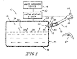
- Fig. 1 is a diagrammatic view of a vehicle fuel system having a filler neck coupled to a fuel tank and a fuel conductor in accordance with the present disclosure interposed between the fuel tank and the filler neck;
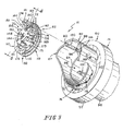
- Fig. 2 is an exploded perspective assembly view of the fuel conductor of Fig. 1 showing (from left to right) a pivotable valve mover, a biasing spring for the valve mover, a two-part diverter valve including a closure and a seal ring, a valve housing, and a housing jacket cooperating with the valve housing to form a valve carrier;
- Fig. 3 is a view similar to Fig. 2 showing a subassembly comprising the diverter valve, valve mover, and biasing spring before it is mounted in the valve housing formed in the valve carrier;
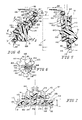
- Fig. 4 is a sectional view of the valve taken along line 4-4 of Fig. 3 showing limited angular motion of the diverter valve relative to the valve mover and showing a portion of the valve housing in phantom;
- Fig. 5 is a view similar to Fig. 4 showing pivoting movement of the diverter valve under a closing force applied by the biasing spring;
- Fig. 6 is a sectional view taken along line 6-6 of Fig. 4 showing limited movement of the diverter valve relative to the valve mover owing to a "lost-motion" coupling of a mounting post included in the diverter valve and a post receiver formed in the valve mover;
- Fig. 7 is a sectional view taken along line 7-7 of Fig. 4 showing a "lost-motion" connection between a mounting post included in the diverter valve and a post receiver formed in the valve mover so as to allow rotary motion of the diverter valve relative to the valve mover in every direction (about an axis extending through the post receiver) within predetermined limits;
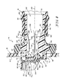
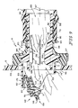
- Fig. 8 is a cross-sectional view of the fuel tank, tank inlet check valve apparatus, and filler neck of Fig. 1 showing the diverter valve in a channel-closing position to block flow of liquid fuel and fuel vapor between the fuel tank and the filler neck;
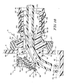
- Fig. 9 is a view similar to Fig. 8 after the diverter valve has been moved to a channel-opening position by a stream of liquid fuel passing through the filler neck during refueling;
- Fig. 10 is a view similar to Figs. 8 and 9 showing a lead end (or tip) of a siphon tube fully inserted through the tank inlet check valve apparatus, a portion of a siphon tube deflector included in the diverter valve having intercepted the lead end of the siphon tube and having directed it to lie substantially adjacent to the bottom wall of the fuel tank as the siphon tube was passed down the filler neck and past the tank inlet check valve apparatus into the fuel tank, and the siphon tube functioning to remove liquid fuel from the fuel tank.
- Fuel system 10 for use with a vehicle is shown in Fig. 1.
- Fuel system 10 includes a fuel tank 18, a vapor-venting system 20 coupled to fuel tank 18 and to a vapor-recovery device 19, and a fuel-transfer system 12 including a filler neck 14 and a fuel conductor 16 coupled to filler neck 14 and coupled to fuel tank 18 to intercept liquid fuel flowing through filler neck 14 into fuel tank 18.
- Filler neck 14 conducts liquid fuel 26 to fuel conductor 16 which regulates the flow of liquid fuel 26 and fuel vapor 28 between filler neck 14 and an interior region 30 of fuel tank 18.
- a siphon tube deflector 31 included in fuel conductor 16 intercepts and guides a siphon tube 32 inserted into fuel conductor 16 from filler neck 14 into interior region 30 of fuel tank 18, as shown in Fig. 10, to allow a mechanic to pump liquid fuel 26 from fuel tank 18 when necessary.
- Vapor venting system 20 regulates venting of fuel vapor 28 extant in a vapor space 34 in interior region 30 of fuel tank 18 to vapor-recovery device 19.
- Fuel tank 18 includes a top wall 40, a bottom wall 42 spaced apart from top wall 40, and a side wall 44 including an inlet aperture 46 as shown in Fig. 1.
- Fuel conductor 16 is mounted to side wall 44 and arranged to extend or be extended through inlet aperture 46 as shown in Fig. 1.
- Filler neck 14 includes a mouth 48 at an outer end and a discharge outlet 50 at an inner end.
- Fuel conductor 16 has an outer end 54 coupled to discharge outlet 50 of filler neck 14 and an inner end 52 arranged to extend into interior region 30 of fuel tank 18.
- Mouth 48 is formed to receive a fuel-dispensing pump nozzle 27 during tank refueling and a closure 56 at all times other than refueling.
- Fuel conductor 16 functions, for example, to divert the flow of liquid fuel 26 into fuel tank 18 from filler neck 14 to establish a barrier configured to block flow of liquid fuel and fuel vapor between filler neck 14 and fuel tank 18 at certain times and to intercept and guide siphon tube 32 from filler neck 14 toward bottom wall 42 of fuel tank 18 when it is necessary to remove liquid fuel from fuel tank 18 using siphon tube 32.
- fuel conductor 16 Prior to refueling, fuel conductor 16 is configured to assume a closed position, as shown in Fig. 8. During refueling, fuel conductor 16 is configured to assume an opened position, as shown in Fig. 9, and divert liquid fuel 26 dispensed into filler neck 14 into interior region 30 of fuel tank 18. After refueling, fuel conductor 16 is reconfigured to assume the closed position shown in Fig. 8.
- siphon tube 32 can be inserted into fuel tank 18 and used to siphon or otherwise pump liquid fuel 26 from fuel tank 18 as shown in Fig. 10. Because liquid fuel 26 collects near bottom wall 42 of fuel tank 18, more liquid fuel 26 can be removed from fuel tank 18 if an inlet end 132 of siphon tube 32 can be positioned to lie adjacent to bottom wall 42 of fuel tank 18.
- Fuel conductor 16 includes a siphon tube deflector 31 that is configured and arranged to divert and guide siphon tube 32 as tube 32 is moved through filler neck 14 toward and into fuel tank 18 as suggested in Fig. 9.
- Siphon tube deflector 31 diverts siphon tube 32 toward bottom wall 42 of fuel tank 18 as it is being introduced into the interior region 30 of fuel tank 18 as shown in Fig. 10.
- inlet end (or tip) 132 of siphon tube 32 is positioned to lie adjacent to bottom wall 42 of fuel tank 18 to enable more liquid fuel 26 to be removed from fuel tank 18.
- Fuel conductor 16 comprises a valve carrier 60 and a tank inlet check valve apparatus 62 as suggested in Figs. 2 and 3.
- Check valve apparatus 62 is coupled to valve carrier 60 for pivotable movement between a closed position shown in Fig. 8 and an opened position shown in Fig. 9. In the closed position, fuel and fuel vapor are not allowed to flow between fuel tank 18 and filler neck 14 through fuel conductor 16. However, in the opened position, fuel and fuel vapor are allowed to flow through fuel conductor 16.
- Valve carrier 60 is formed to include a valve seat 64 and a fuel-transfer channel 66 terminating at the valve seat 64 as shown, for example, in Fig. 8.
- Valve carrier 60 is adapted to be coupled to filler neck 14 and fuel tank 18 as suggested in Figs. 1 and 8 to conduct fuel from filler neck 14 to fuel tank 18 through fuel-transfer channel 66 during vehicle refueling.
- Check valve apparatus 62 is pivotable about a pivot axis 63 (see Fig. 7) relative to valve carrier 60 to the closed position as shown in Fig. 8 to engage valve seat 64 to block discharge of fuel from fuel-transfer channel 66 into fuel tank 18.
- Check valve apparatus 62 can also pivot about pivot axis 63 to the opened position as shown in Fig. 9 to disengage valve seat 64 to allow discharge of fuel from fuel-transfer channel 66 into fuel tank 18.
- Tank inlet check valve apparatus 62 comprises a diverter valve 68 configured to mate with valve seat 64 provided in valve carrier 60, a valve mover 70 pivotably coupled to valve carrier 60 at pivot axis 63 to carry diverter valve 68 toward and away from valve seat 64, an a biasing spring 72 as shown, for example, in Figs. 2, 3, and 8.
- Biasing spring 72 yieldably urges valve mover 70 so as to bias diverter valve 68 normally to the closed position.
- check valve apparatus 62 is a modular assembly and can be "snap-mounted" to valve carrier 60 using first and second pin guide slots 90, 94 and first and second pin receivers 88, 92 formed in valve carrier 60 as suggested in Figs. 2, 3, and 8.
- valve carrier 60 includes a valve housing 74 and a housing jacket 76 overmolded onto valve housing 74 in the manner suggested in Figs. 2 and 8.
- Valve housing 74 is made, for example, of acetyl.
- Housing jacket 76 is made of a permeation-resistant material such as, for example, high-density polyethylene so that it can be welded to fuel tank 18 to support valve housing 74 in a fixed position in aperture 46 formed in side wall 44.
- Check valve apparatus 62 is coupled to valve housing 74 for pivotable movement about pivot axis 63 in the illustrated embodiment.
- Valve mover 70 was designed to be snap-fit to valve carrier 60 and is made of the same material than valve housing 74 to allow unit to function better in "swell" conditions.
- Valve housing 74 includes a pipe 78 having a cylindrical interior wall 80 defining a boundary of fuel-transfer channel 66 as shown, for example, in Fig. 8.
- One end 81 of pipe 78 is open to receive fuel from filler neck 14.
- Valve seat 64 is formed at an opposite downstream end 83 of pipe 78 to define an opening through which fuel is discharged from fuel-transfer channel 66 into fuel tank 18 when check valve apparatus 62 is moved to the opened position as shown, for example, in Fig. 9.
- Valve housing 74 also includes an outer sleeve 82 configured to surround a downstream portion of pipe 78, which portion is formed to include valve seat 64, as shown, for example, in Fig. 8.
- Valve housing 74 further includes a radially outwardly extending annular pipe anchor 84 coupled to an exterior surface of pipe 78 and arranged to mate with housing jacket 76 during the overmolding process.
- Sleeve 82 includes a proximal end 85 coupled to annular pipe anchor 84 to retain sleeve 82 in a cantilevered position relative to valve seat 64 as suggested in Figs. 3 and 8.
- a ramped collar 86 forming a sealing barb is provided on upstream end 81 of pipe 78 as shown in Fig. 8 for expanding filler neck 14 radially outwardly as filler neck 14 is coupled to valve carrier 60.
- an outer end portion 87 of sleeve 82 is formed to include a first pin receiver 88, a first pin guide slot 90 terminating at first pin receiver 88, a second pin receiver 92, and a second pin guide slot 94 terminating at second pin receiver 92.
- These guide slots 90, 94 and receivers 88, 92 are used to mount check valve apparatus 62 to sleeve 82 for pivotable movement about pivot axis 63 to open and close fuel-transfer channel 66 formed in pipe 78.
- Housing jacket 76 includes an outer tube 96 arranged to surround pipe 78, a mounting flange 97 appended to one end of tube 96, and an end collar 98 appended to an opposite end of tube 96 as shown in Fig. 8.
- Mounting flange 97 is adapted to be coupled (using any suitable means) to side wall 44 of fuel tank 18 to fix valve housing 74 in a stationary position extending into inlet aperture 46 formed in side wall 44. It is within the scope of this disclosure to adapt valve carrier 60 for weld-on tank mounting (as shown) or for in-tank mounting.
- Mounting flange 97 is also configured to mate with annular pipe anchor 84 as shown, for example, in Fig. 8.
- a radially outwardly extending annular middle collar 99 is appended to a middle portion of tube 96 and arranged to abut a distal end 95 of filler neck 14 as shown, for example, in Fig. 8. It is within the scope of this disclosure to couple filler neck 14 to valve carrier 60 using cam locks (not shown) or a crimped connector (not shown).
- Diverter valve 68 includes a closure 110 and a seal ring 112 as shown, for example, in Figs. 2-6.
- Closure 110 is coupled to valve mover 70 for movement therewith.
- Closure 110 is made of nylon and seal ring 112 is made of fluorsilicone and overmolded onto closure 110 to provide a mechanical and chemical bond therebetween.
- Seal ring 112 is coupled to closure 110 to move therewith relative to valve seat 64.
- Biasing spring 72 is arranged yieldably to pivot valve mover 70 about pivot axis 63 to move closure 110 normally toward valve seat 64 to trap seal ring 112 between closure 110 and valve seat 64 to locate tank inlet check valve apparatus 62 in the closed position as shown in Fig. 8.
- Closure 110 includes a mover mount 114 coupled to valve mover 70, a seal mount 116 coupled to a peripheral portion of mover mount 114 and coupled to seal ring 112, and siphon tube deflector 31.
- Siphon tube deflector 31 is coupled to mover mount 114 and arranged to extend into fuel-transfer channel 66 upon movement of seal ring 112 to engage valve seat 64.
- Siphon tube deflector 31 is adapted to intercept and guide a siphon tube 32 moving through filler neck 14 into fuel-transfer channel 66 toward a bottom wall 42 of fuel tank 18.
- Seal ring 112 includes an annular inner edge 122 and siphon tube deflector 31 is cantilevered to mover mount 114 to project through an aperture 124 defined by annular inner edge 122 as suggested in Fig. 4.
- Siphon tube deflector 31 includes a ridge 126 adapted to engage a siphon tube 320 extending through filler neck 14 to reach bottom wall 42 of fuel tank 18 upon movement of tank inlet check valve apparatus 62 to the opened position to retain the check valve apparatus 62 in the opened position.
- Siphon tube deflector 31 also includes an inclined surface 128 arranged to extend between mover mount 114 and ridge 126 and intercept a siphon tube 32 passing through fuel-transfer channel 66 and into fuel tank 18 to move valve mover 70 against biasing spring 72 to cause check valve apparatus 62 to move to the opened position.
- Inclined surface 128 is angled to prevent siphon tube 32 from hitting seal ring 112 as siphon tube 32 moves through fuel conductor 16 in addition to directing siphon tube 32 into fuel tank 18.
- Valve carrier 60 includes a plurality of siphon tube guides 130 coupled to interior wall 80 of pipe 78 to lie in fuel-transfer channel 66 and arranged cooperatively to define means for guiding a tip 132 of a siphon tube 32 moving in fuel-transfer channel 66 in a direction toward tank inlet check valve apparatus 62 to intercept in sequence inclined surface 128 and ridge 126 of siphon tube deflector 31 to cause check valve apparatus 62 to move to the opened position in response to continued movement of tip 132 of siphon tube 32 toward bottom wall 42 of fuel tank 18.
- Siphon tube guides 130 are arranged to lie in spaced-apart relation to one another and extend toward a longitudinally extending central axis 137 of pipe 78 to define therebetween a reduced-diameter passageway 134 in fuel-transfer channel 66 sized to receive a siphon tube 32 moving in fuel-transfer channel 66 toward check valve apparatus 62 and guide that siphon tube 20 to engage siphon tube deflector 31 coupled to mover mount 114.
- Interior wall 80 of pipe 78 has a cylindrical shape and the plurality of siphon tube guides 130 are circumferentially spaced apart from one another about interior wall 80 as suggested in Fig. 8.
- Each of siphon tube guides 130 is fin-shaped and cantilevered to interior wall 80 of pipe 78 as suggested in Fig. 8.
- Each of siphon tube guides 130 includes a slide edge 136 arranged to lie in substantially parallel relation to longitudinally extending central axis 137 of pipe 78 and in close proximity to valve seat 64.
- Each siphon tube guide 130 also includes a sloping ramp edge 138 having a leading edge merging with (or lying in close proximity to) interior wall 80 of pipe 78 and a trailing edge merging with slide edge 136 to cause sloping ramp edges 138 of siphon tube guides 130 to converge toward the longitudinally extending central axis 137 of pipe 78 in a direction toward valve seat 64 as suggested in Fig. 8.
- Valve mover 70 is pivotably coupled to sleeve 82 and arranged to lie outside of fuel-transfer channel 66 as shown, for example, in Fig. 8.
- Valve mover 70 includes first and second pivot pins 141, 142 extending in opposite directions from one another to extend respectively into first and second pin receivers 88, 92 formed in sleeve 82.
- Valve mover 70 includes a base pivoter 144 coupled for pivotable movement to valve carrier 60 at pivot axis 63 and a base 146 coupled to base pivoter to pivot therewith and formed to include a post receiver 148 as shown, for example, in Figs. 2 and 3.
- Closure 110 includes an upright mounting post 150 formed to include a central axis extending longitudinally therethrough and arranged to extend through post receiver 148 formed in base 146 to retain closure 70 in coupled relation to base 146 yet allow limited movement of closure 110 relative to base 146 owing to movement of the central axis of mounting post 150 relative to pivot axis 63 during seating on valve seat 64 of seal ring 112 carried on closure 110 during movement of tank inlet check valve apparatus 62 to assume the closed position.
- Base pivoter 144 includes first and second pivot arms 151, 152 cantilevered to base 146, a first pivot pin 141 coupled to first pivot arm 151 and arranged to extend into a first pin receiver 88 formed in sleeve 82 of valve carrier 60 to intersect pivot axis 63, and a second pivot pin 142 coupled to second pivot arm 152 and arranged to extend into a second pin receiver 92 formed in sleeve 82 of valve carrier 60 to intersect pivot axis 63.
- Post receiver 148 has an inner diameter and mounting post 150 includes a post shaft 154 that extends through post receiver 148 and has an outer diameter that is less than the inner diameter of post receiver 148 so as to allow rotary motion of diverter valve 68 relative to valve mover 70 in every direction within predetermined limits.
- This two-piece ball-snap design acts to enhance sealing capability of diverter valve 68 by establishing continuous and positive contact of seal ring 112 on annular valve seat 64.
- Diverter valve 68 is thus self-aligning using a swivel, ball and socket, and/or pivoting mount to allow for a lower load on biasing spring 72. This aids in lower pressure drops, allows for better sealing capabilities and low system pressures, improves air leaks at low pressures, and improves air flow at low pressures.
- Mounting post 150 also includes a post retainer 156 that is coupled to a distal end of post shaft 154 and has an outer diameter that is larger than the inner diameter of post receiver 148 normally to block removal of post shaft 154 from post receiver 148 formed in base 146 of valve mover 70.
- Base 146 is formed to include at least one slit 158 (see Fig. 6) extending radially outwardly from post receiver 148 to form at least two (e.g., four) deformable sections 160 in base that deform temporarily during movement of post retainer 156 through post receiver 148 to locate post shaft 154 in post receiver 148 to couple diverter valve 68 to valve mover 70.
- Valve mover 70 further includes at least one socket pin coupled to base 146 and arranged to extend toward closure 110 as suggested in Fig. 2.
- socket pins 161, 162, 163 are provided.
- Closure 110 is formed to include a socket for each of socket pins 161, 162, 163 as also suggested in Fig. 2.
- Each socket 171, 172, 173 is configured to receive one of the socket pins 161, 162, 163 for sliding movement therein during movement of sealing ring 112 to engage and disengage valve seat 64.
- Three socket pins 161, 162, 163 are appended to a perimeter portion of base 146 as suggested in Fig. 3 and arranged to form vertices of a reference triangle (not shown) receiving base of valve mover 70 therein as suggested in Fig. 6.
- Socket pin 161 has an oblong cross-sectional shape and socket pins 162, 163 have a round cross-sectional shape as suggested in Fig. 2.
- Valve mover 70 further includes a stop member 174 coupled to one of the first and second pivot arms 151, 152. Two stop members 174 are shown in the illustrated embodiment. Each stop member 174 is arranged to engage valve carrier 60 to limit pivoting movement of valve mover 70 about pivot axis 63 against biasing spring 72 in a direction away from valve seat 64 during movement of tank inlet check valve apparatus 62 to the opened position. First and second pivot arms 151, 152 are splayed and cooperate to form an acute included angle therebetween as suggested in Fig. 3.
- each socket pin and its companion socket cooperate to define means for providing a hard stop to limit excessive pivoting movement relative to valve mover 70 during movement of tank inlet check valve apparatus 62 relative to pipe 78.
- Each of the pin guide slots 90, 94 includes an inclined pin-engaging ramp as suggested in Fig. 3.
- Inclined pin-engaging ramps 190, 194 are arranged to converge in a direction extending toward valve seat 64 to cause first and second pivot arms 151, 152 to deform temporarily and move toward one another to guide first pivot pin 141 into first pin receiver 88 and second pivot pin 142 into second pin receiver 92 as valve mover 70 is moved toward valve seat 64 during installation of valve mover 70 in valve carrier 60 whereupon first and second pivot arms 151, 152 are allowed to move away from one another owing to a resilient characteristic thereof to retain first pivot pin 141 in first pin receiver 88 and second pivot pin 142 in second pin receiver 92.
- Pivot arm 152 includes a coil support 153 as shown in Figs. 2 and 3.
- Valve mover 70 includes an arm receiver 180 located between first and second pivot arms 151, 152. Arm receiver 180 holds and/or captures one arm of biasing spring 72 to avoid using alternate costly assembly methods and/or components.
- Biasing spring 72 is shown in Figs. 2 and 3 and includes a coil 182 mounted on coil support 153, a housing arm 184 coupled to coil 182 and biased to engage valve carrier 60, and a mover arm 186 coupled to coil 182 and biased to engage arm receiver 180.
Landscapes
- Engineering & Computer Science (AREA)
- Life Sciences & Earth Sciences (AREA)
- Sustainable Development (AREA)
- Sustainable Energy (AREA)
- Chemical & Material Sciences (AREA)
- Combustion & Propulsion (AREA)
- Transportation (AREA)
- Mechanical Engineering (AREA)
- Cooling, Air Intake And Gas Exhaust, And Fuel Tank Arrangements In Propulsion Units (AREA)
Applications Claiming Priority (2)
| Application Number | Priority Date | Filing Date | Title |
|---|---|---|---|
| US810982 | 1985-12-19 | ||
| US10/810,982 US7147001B2 (en) | 2004-03-26 | 2004-03-26 | Fuel-transfer system |
Publications (1)
| Publication Number | Publication Date |
|---|---|
| EP1580059A1 true EP1580059A1 (de) | 2005-09-28 |
Family
ID=34862117
Family Applications (1)
| Application Number | Title | Priority Date | Filing Date |
|---|---|---|---|
| EP20050251975 Withdrawn EP1580059A1 (de) | 2004-03-26 | 2005-03-29 | Kraftstoffübertragungssystem |
Country Status (2)
| Country | Link |
|---|---|
| US (1) | US7147001B2 (de) |
| EP (1) | EP1580059A1 (de) |
Cited By (1)
| Publication number | Priority date | Publication date | Assignee | Title |
|---|---|---|---|---|
| CN103672050A (zh) * | 2013-12-30 | 2014-03-26 | 斯丹德汽车系统(苏州)有限公司 | 止回阀 |
Families Citing this family (15)
| Publication number | Priority date | Publication date | Assignee | Title |
|---|---|---|---|---|
| US20060180959A1 (en) | 2005-02-17 | 2006-08-17 | Stant Manufacturing Inc. | Method of coupling a component to a fuel fill tube |
| CA2536860C (en) | 2005-02-17 | 2008-12-30 | Stant Manufacturing Inc. | Fuel tank filler neck assembly |
| US20070084525A1 (en) * | 2005-10-07 | 2007-04-19 | Stant Manufacturing Inc. | Fuel tank valve apparatus |
| US20080257426A1 (en) * | 2007-04-19 | 2008-10-23 | Spink Kenneth M | Integral hinge |
| US7779829B2 (en) * | 2008-03-31 | 2010-08-24 | Solfocus, Inc. | Solar thermal collector manifold |
| JP5367465B2 (ja) * | 2009-06-08 | 2013-12-11 | 株式会社パイオラックス | フラップ弁装置 |
| JP5436398B2 (ja) * | 2010-03-26 | 2014-03-05 | 本田技研工業株式会社 | 車両用燃料タンク |
| US8997782B2 (en) | 2010-09-24 | 2015-04-07 | Brunswick Corporation | Inlet control valves for use with fuel delivery systems |
| US8701694B2 (en) | 2011-03-10 | 2014-04-22 | Stant Usa Corp. | Mount for inlet check valve |
| US9022053B2 (en) | 2011-03-10 | 2015-05-05 | Stant Usa Corp. | Mount for inlet check valve |
| KR102103351B1 (ko) | 2012-07-02 | 2020-04-22 | 노마 유.에스. 홀딩 엘엘씨 | 연료 라인 커넥터 및 이를 제조하는 방법 |
| EP2799273B1 (de) * | 2013-05-02 | 2015-07-01 | MAGNA STEYR Fuel Systems GesmbH | Tanksystem |
| US10682906B2 (en) | 2014-10-29 | 2020-06-16 | Stant Usa Corp. | Connector system for fuel hose and filler pipe |
| US11766930B2 (en) * | 2019-09-18 | 2023-09-26 | Ford Global Technologies, Llc | Anti-siphon device and method for operation of an anti-siphon device |
| CN113700906B (zh) * | 2021-09-09 | 2023-10-24 | 永秀阀门有限公司 | 一种多层密封的伸缩蝶阀 |
Citations (6)
| Publication number | Priority date | Publication date | Assignee | Title |
|---|---|---|---|---|
| US2048943A (en) * | 1934-04-21 | 1936-07-28 | Alfred N Munn | Check valve |
| US2247509A (en) * | 1938-11-04 | 1941-07-01 | Protectoseal Co | Filler attachment for gasoline tanks |
| US2312290A (en) * | 1940-11-16 | 1943-02-23 | Crane Co | Valve |
| JPH0796757A (ja) * | 1993-09-29 | 1995-04-11 | Nissan Motor Co Ltd | 燃料タンクのシャッタ構造 |
| EP0864456A2 (de) * | 1997-03-11 | 1998-09-16 | Borg-Warner Automotive, Inc. | Rückschlagventil für Einfüllstutzen eines Kraftstofftanks zur Vermeidung von Kraftstoffleckagen |
| US20030116202A1 (en) * | 2001-12-21 | 2003-06-26 | Eaton Corporation | Assembling a siphonable filler tube with a check vlave on a fuel tank |
Family Cites Families (8)
| Publication number | Priority date | Publication date | Assignee | Title |
|---|---|---|---|---|
| US2578590A (en) * | 1948-02-25 | 1951-12-11 | Perrault Bros | Safety valve |
| US5568828A (en) * | 1994-11-30 | 1996-10-29 | Stant Manufacturing Inc. | Fuel-delivery control system |
| US6234195B1 (en) * | 1998-07-20 | 2001-05-22 | Saturn Electronics & Engineering, Inc. | Check valve for fuel tank fill pipe |
| US6056029A (en) * | 1999-03-03 | 2000-05-02 | Stant Manufacturing Inc. | Fuel-Transfer system |
| JP4276727B2 (ja) * | 1999-03-03 | 2009-06-10 | 株式会社ニフコ | バルブ |
| US6648016B2 (en) * | 2002-01-24 | 2003-11-18 | Alfmeier Corporation | Valve assembly for a fuel tank |
| US6959727B2 (en) * | 2002-04-30 | 2005-11-01 | Eaton Corporation | Siphonable check valve and method of making same |
| US6932100B2 (en) * | 2003-05-23 | 2005-08-23 | Eaton Corporation | Flapper type fill tube check valve |
-
2004
- 2004-03-26 US US10/810,982 patent/US7147001B2/en not_active Expired - Lifetime
-
2005
- 2005-03-29 EP EP20050251975 patent/EP1580059A1/de not_active Withdrawn
Patent Citations (6)
| Publication number | Priority date | Publication date | Assignee | Title |
|---|---|---|---|---|
| US2048943A (en) * | 1934-04-21 | 1936-07-28 | Alfred N Munn | Check valve |
| US2247509A (en) * | 1938-11-04 | 1941-07-01 | Protectoseal Co | Filler attachment for gasoline tanks |
| US2312290A (en) * | 1940-11-16 | 1943-02-23 | Crane Co | Valve |
| JPH0796757A (ja) * | 1993-09-29 | 1995-04-11 | Nissan Motor Co Ltd | 燃料タンクのシャッタ構造 |
| EP0864456A2 (de) * | 1997-03-11 | 1998-09-16 | Borg-Warner Automotive, Inc. | Rückschlagventil für Einfüllstutzen eines Kraftstofftanks zur Vermeidung von Kraftstoffleckagen |
| US20030116202A1 (en) * | 2001-12-21 | 2003-06-26 | Eaton Corporation | Assembling a siphonable filler tube with a check vlave on a fuel tank |
Non-Patent Citations (1)
| Title |
|---|
| PATENT ABSTRACTS OF JAPAN vol. 1995, no. 07 31 August 1995 (1995-08-31) * |
Cited By (1)
| Publication number | Priority date | Publication date | Assignee | Title |
|---|---|---|---|---|
| CN103672050A (zh) * | 2013-12-30 | 2014-03-26 | 斯丹德汽车系统(苏州)有限公司 | 止回阀 |
Also Published As
| Publication number | Publication date |
|---|---|
| US20050211311A1 (en) | 2005-09-29 |
| US7147001B2 (en) | 2006-12-12 |
Similar Documents
| Publication | Publication Date | Title |
|---|---|---|
| US7147001B2 (en) | Fuel-transfer system | |
| US7302977B2 (en) | Fuel-dispensing nozzle inhibitor | |
| US5568828A (en) | Fuel-delivery control system | |
| US5730194A (en) | Capless filler neck closure system | |
| US6554150B2 (en) | Contaminant cover for tank filler neck closure assembly | |
| CN102348569B (zh) | 误加燃料禁止装置 | |
| US7458385B2 (en) | Flapper type fill tube check valve | |
| AU2005225120B2 (en) | Assembling a siphonable filler tube with a check valve on a fuel tank | |
| US6945290B1 (en) | Check valve for use in filler tube vapor recirculation system and method of making same | |
| US11014444B2 (en) | Capless closure assembly for fuel-tank filler pipe | |
| WO1994000351A1 (en) | Capless refueling system with moving fill passageway | |
| EP1456051B1 (de) | Rückschlagventil für einen Kraftstoff-EInfüllstutzen | |
| US6648016B2 (en) | Valve assembly for a fuel tank | |
| EP3969313B1 (de) | Kappenlose verschlussvorrichtung für den einfüllstutzen eines kraftstofftanks | |
| US20120228292A1 (en) | Mount for inlet check valve | |
| US10150061B2 (en) | Separator nipple | |
| US10974589B2 (en) | Capless closure assembly for fuel-tank filler pipe | |
| CA2530556C (en) | Fuel-transfer system | |
| EP1504944A1 (de) | Zum Absaugen geeignetes Sitzventil als Rückschlagventil | |
| US8701694B2 (en) | Mount for inlet check valve | |
| US11325462B2 (en) | Capless closure assembly for fuel-tank filler pipe |
Legal Events
| Date | Code | Title | Description |
|---|---|---|---|
| PUAI | Public reference made under article 153(3) epc to a published international application that has entered the european phase |
Free format text: ORIGINAL CODE: 0009012 |
|
| AK | Designated contracting states |
Kind code of ref document: A1 Designated state(s): AT BE BG CH CY CZ DE DK EE ES FI FR GB GR HU IE IS IT LI LT LU MC NL PL PT RO SE SI SK TR |
|
| AX | Request for extension of the european patent |
Extension state: AL BA HR LV MK YU |
|
| 17P | Request for examination filed |
Effective date: 20051219 |
|
| AKX | Designation fees paid |
Designated state(s): CZ DE FR GB |
|
| 17Q | First examination report despatched |
Effective date: 20060406 |
|
| STAA | Information on the status of an ep patent application or granted ep patent |
Free format text: STATUS: THE APPLICATION IS DEEMED TO BE WITHDRAWN |
|
| 18D | Application deemed to be withdrawn |
Effective date: 20070223 |