EP1580057A2 - Power train supporting apparatus and method for automotive vehicle - Google Patents
Power train supporting apparatus and method for automotive vehicle Download PDFInfo
- Publication number
- EP1580057A2 EP1580057A2 EP05250856A EP05250856A EP1580057A2 EP 1580057 A2 EP1580057 A2 EP 1580057A2 EP 05250856 A EP05250856 A EP 05250856A EP 05250856 A EP05250856 A EP 05250856A EP 1580057 A2 EP1580057 A2 EP 1580057A2
- Authority
- EP
- European Patent Office
- Prior art keywords
- power train
- engine
- mount
- vehicle
- transmission
- Prior art date
- Legal status (The legal status is an assumption and is not a legal conclusion. Google has not performed a legal analysis and makes no representation as to the accuracy of the status listed.)
- Granted
Links
Images


Classifications
-
- B—PERFORMING OPERATIONS; TRANSPORTING
- B60—VEHICLES IN GENERAL
- B60K—ARRANGEMENT OR MOUNTING OF PROPULSION UNITS OR OF TRANSMISSIONS IN VEHICLES; ARRANGEMENT OR MOUNTING OF PLURAL DIVERSE PRIME-MOVERS IN VEHICLES; AUXILIARY DRIVES FOR VEHICLES; INSTRUMENTATION OR DASHBOARDS FOR VEHICLES; ARRANGEMENTS IN CONNECTION WITH COOLING, AIR INTAKE, GAS EXHAUST OR FUEL SUPPLY OF PROPULSION UNITS IN VEHICLES
- B60K5/00—Arrangement or mounting of internal-combustion or jet-propulsion units
- B60K5/12—Arrangement of engine supports
- B60K5/1208—Resilient supports
- B60K5/1216—Resilient supports characterised by the location of the supports relative to the motor or to each other
Definitions
- the present invention relates to power train supporting apparatus and method for an automotive vehicle and, particularly, relates to the power train supporting and method for supporting a power train arranged in a lateral direction with respect to a vehicular longitudinal direction (in this specification, the vehicular longitudinal direction means a vehicular forward-and-backward direction).
- Japanese Patent Application First Publication No. Heisei 9-123770 published on May 13, 1997 exemplifies a previously proposed power train supporting apparatus in which, in a case where a power train constituted by an engine and a transmission is mounted in a lateral direction with respect to a vehicular forward-and-backward direction, a plane including a principal axis of inertia passing through a weight center of the power train and a vertical line is formed, mount portions are arranged in the vicinity of this plane and at least three mount portions are arranged on upper and lower positions of an outer end of the engine and the principal axis of inertia and an upper portion of an outer end of the transmission and the principal axis of inertia.
- the power train is supported at the proximities of the engine outer end and principal axis of inertia and the transmission outer end and the principal axis of inertia, it is difficult for a natural (vibration) frequency in a pitch direction of the power train to be lowered into a relatively low frequency region and it is difficult for a floor vibration during an engine idling excited due to the vibration of the pitch direction of the power train according to a vibration excitation (force) of a rotational inertia of the engine in a case where the power train having the engine in which the vibration in the pitch direction is relatively large is mounted in a lateral direction with respect to the vehicular forward-and-backward direction.
- a vibration excitation force
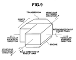
- an object of the present invention to provide power train supporting apparatus and method which are capable of reducing the floor vibration by easily reducing the natural frequency of the power train in the pitch direction to the low frequency region than the vibration frequency at which the floor vibration during the engine idling is generated to be made difficult in exciting the floor vibration. It is noted that a definition of the pitch direction of the power train is shown in Fig. 9.
- a power train supporting apparatus for an automotive vehicle comprising: a power train including an engine and a transmission arranged in series with an output axle of the engine; and at least three mount portions that support the power train on a frame of a vehicle body in such a manner that the output axle of the engine is intersected to a center line of a vehicular longitudinal direction as viewed from a top of the vehicle, the three mount portions comprising engine front and rear side mounts arranged on a vehicular front side and a vehicular rear side with respect to the engine and a transmission side mount arranged in the vicinity to the transmission and being arranged in such a manner that a distance from a weight center of the power train to each of the engine front and rear side mounts is shorter than a distance from the weight center of the power train to the transmission side mount.
- a power train supporting method for an automotive vehicle the automotive vehicle having a power train including an engine and a transmission arranged in series with an output axle of the engine
- the method comprising: providing at least three mount portions that support the power train on a frame of a vehicle body in such a manner that the output axle of the engine is intersected to a center line of a vehicular longitudinal direction as viewed from a top of the vehicle, the three mount portions comprising engine front and rear side mounts arranged on a vehicular front side and a vehicular rear side with respect to the engine and a transmission side mount arranged in the vicinity to the transmission; and arranging the three mount portions on the vehicle body in such a manner that a distance from a weight center of the power train to each of the engine front and rear side mounts is shorter than a distance from the weight center of the power train to the transmission side mount.
- Fig. 1 is a schematic top view of a power train supporting apparatus for an automotive vehicle in a first preferred embodiment according to the present invention.
- Fig. 2 is a schematic front view of the power train supporting apparatus for the automotive vehicle in the first preferred embodiment according to the present invention.
- Fig. 3 is a characteristic graph representing an effect achieved by the power train supporting apparatus in the first embodiment shown in Figs. 1 and 2.
- Fig. 4 is a schematic top view of the power train supporting apparatus for the automotive vehicle in a second preferred embodiment according to the present invention.
- Fig. 5 is a schematic front view of the power train supporting apparatus for the automotive vehicle in the second embodiment shown in Fig. 4.
- Fig. 6 is a characteristic graph representing the effects achieved by the power train supporting apparatus in the second and a third preferred embodiments.
- Fig. 7 is a schematic top view of the power train supporting apparatus in the third preferred embodiment according to the present invention.
- Fig. 8 is a schematic front view of the power train supporting apparatus in the third preferred embodiment.
- Fig. 9 is an explanatory view for explaining a definition of a pitch direction of a power train.
- Fig. 1 shows a schematic top view of a power train supporting apparatus in a first preferred embodiment according to the present invention.
- Fig. 2 shows a schematic (elevation) front view of the power train supporting apparatus shown in Fig. 1.
- a reference symbol G denotes a weight center of a power train 2, an engine 4 and a transmission 6 being integrally mounted into power train 2.
- This power train 2 is arranged in a lateral direction with respect to a vehicular forward-and-backward direction (which, in this specification, has the same meaning as a vehicular longitudinal direction).
- This power train 2 is supported on a frame located at a front side of the vehicle.
- This frame is constituted by a main frame 8 supporting an automotive vehicle body and a sub-frame 10 disposed on a lower position of main frame 8 and is coupled to main frame 8.
- Main frame 8 includes: a pair of left and right main side members 8R and 8L extended in the vehicular forward-and-backward direction; a front cross-member (not shown) which links both front end portions of main side members 8L, 8R and extends in a vehicular width direction (vehicular leftward-and-rightward direction); and a rear cross-member (not shown) which links both of rear end portions of main side members 8L, 8R and extends in the vehicular width direction.
- Sub-frame 10 includes: a pair of left and right sub side members 10L, 10R located at a lower position of main side members 8L, 8R and extended in the vehicular forward-and-backward direction; a sub front cross-member 10F linked between the front end portions of sub side members 10L, 10R; and a sub rear cross-member 10RE which links between rear end portions of sub side member 10R and 10L and extended in the vehicular width direction.
- power train 2 includes engine 4 and transmission 6 arranged in series with an output axle of engine 4 and at least three mount portions (as will be described below) support power train 2 on the frame of the vehicle body in such a manner that the output axle of the engine is intersected to a center line of the vehicular longitudinal direction as viewed from the top of the vehicle.
- Mount members (mount portions) to support power train 2 are as follows: that is to say, an engine front-side mount MT1 is disposed on a vehicular front side with respect to engine 4, an engine rear-side mount MT2 is disposed on a vehicular rear side with respect to engine 4, and a transmission side mount MT3 is disposed on an outer end of transmission 6.
- a vertical plane including a principal axis of inertia TR is interposed between two mounts MT1 and MT2 disposed on front and rear sides of engine 4.
- principal axis of inertia TR is an axis such that, when a rigid body is rotated about a certain axis, a moment such as to change a direction of the rotating axis is not generated as viewed from a coordinate system which rotates together with the rigid body and is natural (or inherent) to the power train.
- this principal axis of inertia TR is resided with a descending gradient as the vehicular position is directed from the vehicular right side toward the vehicular left side, as shown in Fig. 2. As shown in Fig.
- mounts MT1 through MT3 are arranged such that an inertia principal axis direction distance L1 from weight center G to a straight line connecting between engine front side mount MT1 and engine rear side mount MT2 is shorter than an inertia principal axis direction distance L2 from weight center G to transmission side mount MT3.
- the natural frequency of the power train in the pitch direction has a relationship such that as the distance from each engine mount to the weight center of the power train is increased or a rigidity of engine mount is increased, the natural frequency thereof is increased.
- the rigidity of each engine mount cannot be reduced more than a value determined from a load of the power train and a power train static deflection regulation value.
- the power train is supported at the proximities of the engine outer end in the vicinity of the principal axis of inertia and transmission outer ends in the vicinity of the principal axis of inertia.
- the distance from the weight center of the power train to each engine mount is large (long) and the load of the power train is applied to all engine mounts.
- engine front-and rear-side mounts and transmission side mount MT1 through MT3 are arranged as shown in Figs. 1 and 2.
- the distance from the weight center of the power train can be shortened.
- the transmission mount MT3 the power train load to be supported is reduced so that a mount rigidity can be reduced.
- the rigidity of each engine mount and the distance from the weight center of the power train to the engine mount, both determining the natural frequency of the power train in the pitch direction can be reduced. It is advantageous over the previously proposed power train supporting apparatus to set the natural frequency of the power train in the pitch direction to the low frequency region. Consequently, the floor vibration during the engine idling excited according to the vibration in the pitch direction of the power train can be improved.
- Fig. 3 shows results of investigating the floor vibration during the idling in the vehicle in which the previously proposed power train supporting apparatus is mounted and in the vehicle in which the power train supporting apparatus in the first embodiment is mounted.
- a lateral axis denotes an excitation frequency and a longitudinal axis denotes an acceleration level of the floor vibration.
- the idling floor vibrations are compared between the previously proposed power train supporting apparatus and the power train supporting apparatus in this embodiment.
- a solid line denotes the case of the vehicle in which the power train supporting apparatus in the first embodiment is mounted and a dot line denotes the case of the vehicle in which the previously proposed power train supporting apparatus is mounted.
- the floor vibration during the engine idling is reduced as compared with the vehicle in which the previously proposed power train supporting apparatus is mounted.
- the weight center of the power train constituted by engine 4 and transmission 6 is taken into consideration and the power train is supported with the distance in the direction of the principal axis of inertia from the weight center of the power train to the straight line connecting engine front side and rear side mounts shorter than the distance from the weight center of the power train to transmission side mount.
- the natural frequency of the power train in the pitch direction becomes easy to be reduced in the low frequency region and the floor vibration during the engine idling excited due to the vibration of the power train in the pitch direction according to the rotational inertia excitation force of engine 4 can be improved.
- Fig. 4 shows a schematic top view of the power train supporting apparatus in a second preferred embodiment according to the present invention.
- Fig. 5 shows a schematic elevation (front view) of the power train supporting apparatus in the second embodiment according to the present invention. As shown in Fig.
- engine front-and rear-side mounts MT1 and MT2 are mounted with principal axis of inertia TR of the power train made (approximately) coincident with engine front and rear-side mounts MT1 and MT2 (in other words, principal axis of inertia TR of the power train is intersected with a line connecting between engine front-and rear-side mounts MT1 and MT2) .
- the principal axis TR of the power train is ordinarily slanted with respect to an input axis of an engine roll direction due to a combustion excitation force of the engine. Therefore, as viewed from the front view of the vehicle shown in Fig. 2, in the first embodiment of the power train supporting apparatus in which the engine front-and rear-side mounts and transmission side mount are arranged so as to be substantially made coincident with the input axis of the engine roll direction, in addition to the roll direction vibration is excited due to a torque variation according to the engine combustion excitation force, the vibrations in other directions are excited. Since a plurality of excited vibrations are easy to be coupled, the floor vibration during the engine idling becomes worsened. However, in this embodiment as shown in Figs.
- the positions of engine front-and rear-side mounts MT1, MT2 and transmission side mount MT3 are arranged so as to be substantially coincident with principle axis TR of inertia as viewed from the front side of the vehicle.
- the vibrations excited due to the torque variation according to the engine combustion excitation force can be concentrated to the vibrations around principal axis TR of inertia of the power train.
- the plurality of excited vibrations become difficult to be coupled. Consequently, the floor vibration during the engine idling can be improved.
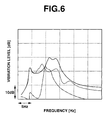
- Fig. 6 shows the result of a comparison of the floor vibration during the engine idling between the vehicles in which power train supporting apparatus in the first embodiment is mounted and in which the power train supporting apparatus in the second embodiment is mounted.
- a lateral axis of Fig. 6 denotes an excitation frequency and a longitudinal axis thereof denotes the acceleration level of the floor vibration.
- a solid line in Fig. 6 denotes the floor vibration of the vehicle in which the power train supporting apparatus in the first embodiment is mounted.
- a dot line in Fig. 6 denotes the floor vibration of the vehicle in which the power supporting apparatus in the second embodiment is mounted.
- the vehicle in which the power train supporting apparatus in the second embodiment is mounted furthermore reduced the floor vibration during the engine idling as compared with the vehicle in which the power train supporting apparatus in the first embodiment is mounted.
- the weight center of the power train including the engine and the transmission is considered, the distance in the direction of the principal axis of inertia from the weight center of the power train to the straight line connecting between the engine front and rear side mounts is arranged to be shorter than the distance from the weight center to the transmission mount, and, as viewed from the front side of the vehicle, engine front-and rear-side mounts MT1 and MT2 are arranged to be coincident with principal axis of inertia TR of the power train.
- the vibration in the roll direction of the engine excited due to the torque variation according to the engine combustion excitation force can be made difficult to be coupled to the other vibrations.
- the engine front-and rear-side mounts are arranged to be coincident with principal axis TR of inertia of the power train.
- the engine front-and rear-side mounts may substantially be coincident with the principal axis of the inertia.
- a straight line connecting between engine front-and rear-side mounts MT1 and MT2 may be intersected with principal axis TR of inertia of power train 2.
- a third preferred embodiment of the power train supporting apparatus will be described below.
- engine front-and rear-side mounts MT1 and MT2 are arranged in such a way that the straight line connecting between engine front-and rear-side mounts MT1 and MT2 is placed in the vicinity to weight center G of the power train.
- Fig. 7 shows a schematic plan (top) view of the power train supporting apparatus in the third preferred embodiment according to the present invention.
- Fig. 8 shows a schematic elevation (front) view of the power train supporting apparatus in the third embodiment. As shown in Figs. 7 and 8, the straight line connecting between engine front-side mount MT1 and engine rear side mount MT2 is positioned in the vicinity to weight center G of power train 2.
- the distances from a rotation center of the roll direction vibration of the power train to engine front-side mount MT1 and to engine rear-side mount MT2 are substantially equal to each other.
- forces inputted from engine front-side mount MT1 and engine rear-side mount MT2 to a vehicle body due to the vibration in the roll direction of the power train are substantially equal to each other but their phases are opposite to each other.
- the input from engine front-side mount MT1 is canceled from the input from engine rear-side mount MT2.
- the floor vibration during the engine idling can be improved.
- the distance of the engine side mounts from the weight center of the power train can furthermore be shortened and the load of the power train which transmission side mount MT3 supports can furthermore be reduced.
- the natural (vibration) frequency in the pitch direction of the power train can be set toward the lower frequency region than the case of the first embodiment.
- the floor vibration during the engine idling excited by means of the pitch direction vibration of the power train can furthermore be improved.
- FIG. 6 denotes that of the vehicle in which the power train supporting apparatus in the third embodiment is mounted. As shown in Fig. 6, it will be appreciated that, in the vehicle in which the power train supporting apparatus in the third embodiment is mounted, the floor vibration during the engine idling can furthermore be reduced as compared with the first embodiment denoted in the solid line and the second embodiment denoted in the dot line can furthermore be reduced.
- engine front-and rear-side mounts MT1 and MT2 are arranged in such a way that the straight line connecting between the engine front-and rear-side mounts is positioned in the vicinity to weight center G of the power train.
- the forces transmitted from engine front-side mount MT1 and engine rear-side mount MT2 to the vehicle are substantially equal to each other and their phases are opposite to each other.
- the cancellation between both forces can furthermore improve the floor vibration during the engine idling.
- an engine mount bracket connecting between the engine mounts and the sub-frame can be reduced, the rigidity of the bracket can be improved so that a noise during a vehicular acceleration can be improved and its cost can be reduced.
Abstract
Description
- The present invention relates to power train supporting apparatus and method for an automotive vehicle and, particularly, relates to the power train supporting and method for supporting a power train arranged in a lateral direction with respect to a vehicular longitudinal direction (in this specification, the vehicular longitudinal direction means a vehicular forward-and-backward direction).
- Japanese Patent Application First Publication No. Heisei 9-123770 published on May 13, 1997 exemplifies a previously proposed power train supporting apparatus in which, in a case where a power train constituted by an engine and a transmission is mounted in a lateral direction with respect to a vehicular forward-and-backward direction, a plane including a principal axis of inertia passing through a weight center of the power train and a vertical line is formed, mount portions are arranged in the vicinity of this plane and at least three mount portions are arranged on upper and lower positions of an outer end of the engine and the principal axis of inertia and an upper portion of an outer end of the transmission and the principal axis of inertia.
- However, since, in the previously proposed power train supporting apparatus disclosed in the above-described Japanese Patent Application First Publication, the power train is supported at the proximities of the engine outer end and principal axis of inertia and the transmission outer end and the principal axis of inertia, it is difficult for a natural (vibration) frequency in a pitch direction of the power train to be lowered into a relatively low frequency region and it is difficult for a floor vibration during an engine idling excited due to the vibration of the pitch direction of the power train according to a vibration excitation (force) of a rotational inertia of the engine in a case where the power train having the engine in which the vibration in the pitch direction is relatively large is mounted in a lateral direction with respect to the vehicular forward-and-backward direction.
- It is, hence, an object of the present invention to provide power train supporting apparatus and method which are capable of reducing the floor vibration by easily reducing the natural frequency of the power train in the pitch direction to the low frequency region than the vibration frequency at which the floor vibration during the engine idling is generated to be made difficult in exciting the floor vibration. It is noted that a definition of the pitch direction of the power train is shown in Fig. 9.
- According to one aspect of the present invention, there is provided a power train supporting apparatus for an automotive vehicle, comprising: a power train including an engine and a transmission arranged in series with an output axle of the engine; and at least three mount portions that support the power train on a frame of a vehicle body in such a manner that the output axle of the engine is intersected to a center line of a vehicular longitudinal direction as viewed from a top of the vehicle, the three mount portions comprising engine front and rear side mounts arranged on a vehicular front side and a vehicular rear side with respect to the engine and a transmission side mount arranged in the vicinity to the transmission and being arranged in such a manner that a distance from a weight center of the power train to each of the engine front and rear side mounts is shorter than a distance from the weight center of the power train to the transmission side mount.
- According to another aspect of the present invention, there is provided a power train supporting method for an automotive vehicle, the automotive vehicle having a power train including an engine and a transmission arranged in series with an output axle of the engine, the method comprising: providing at least three mount portions that support the power train on a frame of a vehicle body in such a manner that the output axle of the engine is intersected to a center line of a vehicular longitudinal direction as viewed from a top of the vehicle, the three mount portions comprising engine front and rear side mounts arranged on a vehicular front side and a vehicular rear side with respect to the engine and a transmission side mount arranged in the vicinity to the transmission; and arranging the three mount portions on the vehicle body in such a manner that a distance from a weight center of the power train to each of the engine front and rear side mounts is shorter than a distance from the weight center of the power train to the transmission side mount.
- This summary of the invention does not necessarily describe all necessary features so that the present invention may also be sub-combination of these described features.
- Fig. 1 is a schematic top view of a power train supporting apparatus for an automotive vehicle in a first preferred embodiment according to the present invention.
- Fig. 2 is a schematic front view of the power train supporting apparatus for the automotive vehicle in the first preferred embodiment according to the present invention.
- Fig. 3 is a characteristic graph representing an effect achieved by the power train supporting apparatus in the first embodiment shown in Figs. 1 and 2.
- Fig. 4 is a schematic top view of the power train supporting apparatus for the automotive vehicle in a second preferred embodiment according to the present invention.
- Fig. 5 is a schematic front view of the power train supporting apparatus for the automotive vehicle in the second embodiment shown in Fig. 4.
- Fig. 6 is a characteristic graph representing the effects achieved by the power train supporting apparatus in the second and a third preferred embodiments.
- Fig. 7 is a schematic top view of the power train supporting apparatus in the third preferred embodiment according to the present invention.
- Fig. 8 is a schematic front view of the power train supporting apparatus in the third preferred embodiment.
- Fig. 9 is an explanatory view for explaining a definition of a pitch direction of a power train.
- Reference will hereinafter be made to the drawings in order to facilitate a better understanding of the present invention.
- Fig. 1 shows a schematic top view of a power train supporting apparatus in a first preferred embodiment according to the present invention. Fig. 2 shows a schematic (elevation) front view of the power train supporting apparatus shown in Fig. 1. In Figs. 1 and 2, a reference symbol G denotes a weight center of a
power train 2, anengine 4 and atransmission 6 being integrally mounted intopower train 2. Thispower train 2 is arranged in a lateral direction with respect to a vehicular forward-and-backward direction (which, in this specification, has the same meaning as a vehicular longitudinal direction). - This
power train 2 is supported on a frame located at a front side of the vehicle. This frame is constituted by amain frame 8 supporting an automotive vehicle body and asub-frame 10 disposed on a lower position ofmain frame 8 and is coupled tomain frame 8.Main frame 8 includes: a pair of left and rightmain side members main side members main side members Sub-frame 10 includes: a pair of left and rightsub side members main side members sub front cross-member 10F linked between the front end portions ofsub side members sub side member power train 2 includesengine 4 andtransmission 6 arranged in series with an output axle ofengine 4 and at least three mount portions (as will be described below) supportpower train 2 on the frame of the vehicle body in such a manner that the output axle of the engine is intersected to a center line of the vehicular longitudinal direction as viewed from the top of the vehicle. - Mount members (mount portions) to support
power train 2 are as follows: that is to say, an engine front-side mount MT1 is disposed on a vehicular front side with respect toengine 4, an engine rear-side mount MT2 is disposed on a vehicular rear side with respect toengine 4, and a transmission side mount MT3 is disposed on an outer end oftransmission 6. As shown in Fig. 1, a vertical plane including a principal axis of inertia TR is interposed between two mounts MT1 and MT2 disposed on front and rear sides ofengine 4. It is noted that principal axis of inertia TR is an axis such that, when a rigid body is rotated about a certain axis, a moment such as to change a direction of the rotating axis is not generated as viewed from a coordinate system which rotates together with the rigid body and is natural (or inherent) to the power train. In addition, this principal axis of inertia TR is resided with a descending gradient as the vehicular position is directed from the vehicular right side toward the vehicular left side, as shown in Fig. 2. As shown in Fig. 2, mounts MT1 through MT3 are arranged such that an inertia principal axis direction distance L1 from weight center G to a straight line connecting between engine front side mount MT1 and engine rear side mount MT2 is shorter than an inertia principal axis direction distance L2 from weight center G to transmission side mount MT3. - It is known that a rotational inertia excitation force of a three-cylinder engine excites the vibration of the power train in the pitch direction. In order to improve a floor vibration during an engine idling due to the vibration of the power train in the pitch direction, it is necessary to set the natural frequency in the pitch direction to a low frequency region.
- The natural frequency of the power train in the pitch direction has a relationship such that as the distance from each engine mount to the weight center of the power train is increased or a rigidity of engine mount is increased, the natural frequency thereof is increased. In addition, the rigidity of each engine mount cannot be reduced more than a value determined from a load of the power train and a power train static deflection regulation value.
- In the previously proposed power train supporting apparatus described in the introduction to the description, the power train is supported at the proximities of the engine outer end in the vicinity of the principal axis of inertia and transmission outer ends in the vicinity of the principal axis of inertia. The distance from the weight center of the power train to each engine mount is large (long) and the load of the power train is applied to all engine mounts. Hence, in the structure of the previously proposed power train supporting apparatus, it is difficult to reduce the rigidity of the engine mount and the distance from the weight center of the power train to each engine mount both determining the natural frequency in the pitch direction of the power train. It is disadvantageous to set the natural frequency of the power train in the pitch direction to the low frequency region. Hence, the floor vibration during the engine idling excited according to the vibration of the power train in the pitch direction cannot be reduced.
- However, in this embodiment, engine front-and rear-side mounts and transmission side mount MT1 through MT3 are arranged as shown in Figs. 1 and 2. Hence, for each of engine front-and rear-side mounts MT1 and MT2, the distance from the weight center of the power train can be shortened. For the transmission mount MT3, the power train load to be supported is reduced so that a mount rigidity can be reduced. Thus, the rigidity of each engine mount and the distance from the weight center of the power train to the engine mount, both determining the natural frequency of the power train in the pitch direction, can be reduced. It is advantageous over the previously proposed power train supporting apparatus to set the natural frequency of the power train in the pitch direction to the low frequency region. Consequently, the floor vibration during the engine idling excited according to the vibration in the pitch direction of the power train can be improved.
- Fig. 3 shows results of investigating the floor vibration during the idling in the vehicle in which the previously proposed power train supporting apparatus is mounted and in the vehicle in which the power train supporting apparatus in the first embodiment is mounted. In Fig. 3, a lateral axis denotes an excitation frequency and a longitudinal axis denotes an acceleration level of the floor vibration. In Fig. 3, the idling floor vibrations are compared between the previously proposed power train supporting apparatus and the power train supporting apparatus in this embodiment. In Fig. 3, a solid line denotes the case of the vehicle in which the power train supporting apparatus in the first embodiment is mounted and a dot line denotes the case of the vehicle in which the previously proposed power train supporting apparatus is mounted.
- As appreciated from Fig. 3, in the vehicle in which the power train supporting apparatus is mounted, the floor vibration during the engine idling is reduced as compared with the vehicle in which the previously proposed power train supporting apparatus is mounted. As described above, in the first embodiment, the weight center of the power train constituted by
engine 4 andtransmission 6 is taken into consideration and the power train is supported with the distance in the direction of the principal axis of inertia from the weight center of the power train to the straight line connecting engine front side and rear side mounts shorter than the distance from the weight center of the power train to transmission side mount. Hence, the natural frequency of the power train in the pitch direction becomes easy to be reduced in the low frequency region and the floor vibration during the engine idling excited due to the vibration of the power train in the pitch direction according to the rotational inertia excitation force ofengine 4 can be improved. - Next, a second preferred embodiment of the power train supporting apparatus according to the present invention will be described below. Fig. 4 shows a schematic top view of the power train supporting apparatus in a second preferred embodiment according to the present invention. Fig. 5 shows a schematic elevation (front view) of the power train supporting apparatus in the second embodiment according to the present invention. As shown in Fig. 5, engine front-and rear-side mounts MT1 and MT2 are mounted with principal axis of inertia TR of the power train made (approximately) coincident with engine front and rear-side mounts MT1 and MT2 (in other words, principal axis of inertia TR of the power train is intersected with a line connecting between engine front-and rear-side mounts MT1 and MT2) .
- The principal axis TR of the power train is ordinarily slanted with respect to an input axis of an engine roll direction due to a combustion excitation force of the engine. Therefore, as viewed from the front view of the vehicle shown in Fig. 2, in the first embodiment of the power train supporting apparatus in which the engine front-and rear-side mounts and transmission side mount are arranged so as to be substantially made coincident with the input axis of the engine roll direction, in addition to the roll direction vibration is excited due to a torque variation according to the engine combustion excitation force, the vibrations in other directions are excited. Since a plurality of excited vibrations are easy to be coupled, the floor vibration during the engine idling becomes worsened. However, in this embodiment as shown in Figs. 4 and 5, the positions of engine front-and rear-side mounts MT1, MT2 and transmission side mount MT3 are arranged so as to be substantially coincident with principle axis TR of inertia as viewed from the front side of the vehicle. Hence, the vibrations excited due to the torque variation according to the engine combustion excitation force can be concentrated to the vibrations around principal axis TR of inertia of the power train. In addition, the plurality of excited vibrations become difficult to be coupled. Consequently, the floor vibration during the engine idling can be improved.
- Fig. 6 shows the result of a comparison of the floor vibration during the engine idling between the vehicles in which power train supporting apparatus in the first embodiment is mounted and in which the power train supporting apparatus in the second embodiment is mounted. A lateral axis of Fig. 6 denotes an excitation frequency and a longitudinal axis thereof denotes the acceleration level of the floor vibration. A solid line in Fig. 6 denotes the floor vibration of the vehicle in which the power train supporting apparatus in the first embodiment is mounted. A dot line in Fig. 6 denotes the floor vibration of the vehicle in which the power supporting apparatus in the second embodiment is mounted. As appreciated from the result of Fig. 6, the vehicle in which the power train supporting apparatus in the second embodiment is mounted furthermore reduced the floor vibration during the engine idling as compared with the vehicle in which the power train supporting apparatus in the first embodiment is mounted.
- As described above, in the second embodiment of the power train supporting apparatus, the weight center of the power train including the engine and the transmission is considered, the distance in the direction of the principal axis of inertia from the weight center of the power train to the straight line connecting between the engine front and rear side mounts is arranged to be shorter than the distance from the weight center to the transmission mount, and, as viewed from the front side of the vehicle, engine front-and rear-side mounts MT1 and MT2 are arranged to be coincident with principal axis of inertia TR of the power train. Hence, the vibration in the roll direction of the engine excited due to the torque variation according to the engine combustion excitation force can be made difficult to be coupled to the other vibrations. The floor vibration during the idling can furthermore be improved. It is noted that, in the second embodiment, as viewed from the front view of the vehicle, the engine front-and rear-side mounts are arranged to be coincident with principal axis TR of inertia of the power train. However, the present invention is not limited to this. The engine front-and rear-side mounts may substantially be coincident with the principal axis of the inertia. In other words, as viewed from the front side of the vehicle, a straight line connecting between engine front-and rear-side mounts MT1 and MT2 may be intersected with principal axis TR of inertia of
power train 2. - Next, a third preferred embodiment of the power train supporting apparatus will be described below. In the third embodiment, engine front-and rear-side mounts MT1 and MT2 are arranged in such a way that the straight line connecting between engine front-and rear-side mounts MT1 and MT2 is placed in the vicinity to weight center G of the power train. Fig. 7 shows a schematic plan (top) view of the power train supporting apparatus in the third preferred embodiment according to the present invention. Fig. 8 shows a schematic elevation (front) view of the power train supporting apparatus in the third embodiment. As shown in Figs. 7 and 8, the straight line connecting between engine front-side mount MT1 and engine rear side mount MT2 is positioned in the vicinity to weight center G of
power train 2. In this arrangement, the distances from a rotation center of the roll direction vibration of the power train to engine front-side mount MT1 and to engine rear-side mount MT2 are substantially equal to each other. Thus, forces inputted from engine front-side mount MT1 and engine rear-side mount MT2 to a vehicle body due to the vibration in the roll direction of the power train are substantially equal to each other but their phases are opposite to each other. Thus, the input from engine front-side mount MT1 is canceled from the input from engine rear-side mount MT2. The floor vibration during the engine idling can be improved. - In the third embodiment, as far as the rigidity of each engine mount determining the natural frequency in the pitch direction of the power train and the distance from the weight center of the power train to each engine mount are concerned with respect to the first embodiment, the distance of the engine side mounts from the weight center of the power train can furthermore be shortened and the load of the power train which transmission side mount MT3 supports can furthermore be reduced. Thus, it becomes possible to set the natural (vibration) frequency in the pitch direction of the power train can be set toward the lower frequency region than the case of the first embodiment. Then, the floor vibration during the engine idling excited by means of the pitch direction vibration of the power train can furthermore be improved. A dot-and-dash line shown in Fig. 6 denotes that of the vehicle in which the power train supporting apparatus in the third embodiment is mounted. As shown in Fig. 6, it will be appreciated that, in the vehicle in which the power train supporting apparatus in the third embodiment is mounted, the floor vibration during the engine idling can furthermore be reduced as compared with the first embodiment denoted in the solid line and the second embodiment denoted in the dot line can furthermore be reduced.
- As described above, in the third embodiment, engine front-and rear-side mounts MT1 and MT2 are arranged in such a way that the straight line connecting between the engine front-and rear-side mounts is positioned in the vicinity to weight center G of the power train. Hence, the forces transmitted from engine front-side mount MT1 and engine rear-side mount MT2 to the vehicle are substantially equal to each other and their phases are opposite to each other. Thus, the cancellation between both forces can furthermore improve the floor vibration during the engine idling.
- In addition, since, in each embodiment, an engine mount bracket connecting between the engine mounts and the sub-frame can be reduced, the rigidity of the bracket can be improved so that a noise during a vehicular acceleration can be improved and its cost can be reduced.
- The entire contents of a Japanese Patent Application No. 2004-087061 (filed in Japan on March 24, 2004) are herein incorporated by reference. The scope of the invention is defined with reference to the following claims.
Claims (9)
- A power train supporting apparatus for an automotive vehicle, comprising:a power train (2) including an engine (4) and a transmission (6) arranged in series with an output axle of the engine; andat least three mount portions that support the power train on a frame of a vehicle body in such a manner that the output axle of the engine is intersected to a center line of a vehicular longitudinal direction as viewed from a top of the vehicle, the three mount portions comprising engine front and rear side mounts (MT1, MT2) arranged on a vehicular front side and a vehicular rear side with respect to the engine (4) and a transmission side mount (MT3) arranged in the vicinity of the transmission and being arranged in such a manner that a distance from a weight center (G) of the power train (2) to each of the engine front and rear side mounts (MT1, MT2) is shorter than a distance from the weight center (G) of the power train to the transmission side mount (MT3).
- A power train supporting apparatus for an automotive vehicle as claimed in claim 1, wherein the mount portions are arranged on the vehicle body in such a manner that a distance (L1) in a direction of a principal axis (TR) of inertia from the weight center (G) of the power train (2) to a straight line connecting both of the engine front and rear side mounts (MT1, MT2) is shorter than the distance (L2) in the direction of the principal axis of inertia from the weight center (G) of the power train (2) to the transmission side mount (MT3).
- A power train supporting apparatus for an automotive vehicle as claimed in claim 2, wherein the mount portions are arranged on the vehicle body in such a manner that the transmission side mount (MT3) is arranged in the vicinity of the principal axis (TR) of inertia passing through the weight center (G) of the power train (2) and in the vicinity of the transmission and the engine front and rear side mounts (MT1, MT2) are arranged to be coincident with the principal axis (TR) of inertia as viewed from a front side (Fig.5) of the vehicle.
- A power train supporting apparatus for an automotive vehicle as claimed in claim 2, wherein the mount portions are arranged on the vehicle body in such a manner that the transmission side mount (MT3) is arranged in the vicinity of the principal axis (TR) of inertia passing through the weight center (G) of the power train (2) and in the vicinity of the transmission and the engine front and rear side mounts (MT1, MT2) are arranged to be approximately coincident with the principal axis (TR) of inertia as viewed from a front side (Fig.5) of the vehicle.
- A power train supporting apparatus for an automotive vehicle as claimed in claim 2, wherein the engine front and rear side mounts (MT1, MT2) are arranged on the vehicle body in such a manner that at least engine front and rear side mounts (MT1, MT2) are substantially coincident with the principal axis of inertia as viewed from a front side (Fig. 5) of the vehicle.
- A power train supporting apparatus for an automotive vehicle as claimed in claim 2, wherein the engine front and rear side mounts are arranged on the vehicle body in such a manner that the straight line connecting the engine front and rear side mounts (MT1, MT2) is intersected to the principal axis of inertia as viewed from a front side (Fig. 5) of the vehicle.
- A power train supporting apparatus for an automotive vehicle as claimed in any one of the preceding claims 1 through 6, wherein the mount portions are arranged on the vehicle body in such a manner that a straight line connecting both of the engine front and rear side mounts (MT1, MT2) is positioned in the vicinity of the weight center (G) of the power train (2) as viewed from a front side (Fig. 8) of the vehicle.
- A power train supporting apparatus for an automotive vehicle as claimed in any one of the preceding claims 1 through 6, wherein the mount portions are arranged on the vehicle body in such a manner that distances from a rotational center of a vibration in a roll direction of the power train to the engine front side mount (MT1) and to the engine rear side mount (MT2) are substantially equal to each other.
- A power train supporting method for an automotive vehicle, the automotive vehicle having a power train (2) including an engine (4) and a transmission (6) arranged in series with an output axle of the engine (4), the method comprising:providing at least three mount portions that support the power train on a frame of a vehicle body in such a manner that the output axle of the engine is intersected to a center line of a vehicular longitudinal direction as viewed from a top of the vehicle, the three mount portions comprising engine front and rear side mounts (MT1, MT2) arranged on a vehicular front side and a vehicular rear side with respect to the engine (4) and a transmission side mount (MT3) arranged in the vicinity of the transmission; and arranging the three mount portions on the vehicle body in such a manner that a distance from a weight center (G) of the power train (2) to each of the engine front and rear side mounts (MT1, MT2) is shorter than a distance from the weight center (G) of the power train (2) to the transmission side mount (MT3).
Applications Claiming Priority (2)
| Application Number | Priority Date | Filing Date | Title |
|---|---|---|---|
| JP2004087061 | 2004-03-24 | ||
| JP2004087061 | 2004-03-24 |
Publications (3)
| Publication Number | Publication Date |
|---|---|
| EP1580057A2 true EP1580057A2 (en) | 2005-09-28 |
| EP1580057A3 EP1580057A3 (en) | 2008-06-11 |
| EP1580057B1 EP1580057B1 (en) | 2013-04-24 |
Family
ID=34858433
Family Applications (1)
| Application Number | Title | Priority Date | Filing Date |
|---|---|---|---|
| EP05250856.1A Expired - Fee Related EP1580057B1 (en) | 2004-03-24 | 2005-02-15 | Power train supporting apparatus and method for automotive vehicle |
Country Status (3)
| Country | Link |
|---|---|
| US (1) | US7328767B2 (en) |
| EP (1) | EP1580057B1 (en) |
| CN (1) | CN1330509C (en) |
Families Citing this family (7)
| Publication number | Priority date | Publication date | Assignee | Title |
|---|---|---|---|---|
| US7819220B2 (en) * | 2006-07-28 | 2010-10-26 | Polaris Industries Inc. | Side-by-side ATV |
| US8827028B2 (en) * | 2006-07-28 | 2014-09-09 | Polaris Industries Inc. | Side-by-side ATV |
| FR2950002B1 (en) * | 2009-09-11 | 2012-02-03 | Peugeot Citroen Automobiles Sa | SUSPENSION ASSEMBLY OF A VIBRATION GENERATING ORGAN FIXED INSIDE A ROLLING AXLE OF A MOTOR VEHICLE |
| EP2505407B1 (en) * | 2009-11-26 | 2019-07-17 | Nissan Motor Co., Ltd. | Three-cylinder engine |
| US20120090912A1 (en) * | 2010-10-14 | 2012-04-19 | Gm Global Technology Operations, Inc. | Mounting Systems for Transverse Front Wheel Drive Powertrains with Decoupled Pitch Damping |
| WO2015060162A1 (en) * | 2013-10-24 | 2015-04-30 | トヨタ自動車株式会社 | Vehicle with engine mount section |
| US11371450B2 (en) * | 2018-06-07 | 2022-06-28 | Eaton Intelligent Power Limited | NVH management in diesel CDA modes |
Citations (2)
| Publication number | Priority date | Publication date | Assignee | Title |
|---|---|---|---|---|
| JPH09123770A (en) | 1995-10-31 | 1997-05-13 | Suzuki Motor Corp | Engine mounting system |
| JP2004087061A (en) | 2002-08-29 | 2004-03-18 | Kuroda Techno Co Ltd | Floating supporter for disk |
Family Cites Families (18)
| Publication number | Priority date | Publication date | Assignee | Title |
|---|---|---|---|---|
| US1103524A (en) * | 1913-03-07 | 1914-07-14 | Nordyke & Marmon Company | Power-train mounting for automobiles. |
| US2346123A (en) * | 1941-05-20 | 1944-04-04 | Corwin D Willson | Suspension system for vehicles |
| JPS5784266A (en) * | 1980-11-11 | 1982-05-26 | Mazda Motor Corp | Chassis structure of rear suspension tower part |
| JPS57144126A (en) * | 1981-03-04 | 1982-09-06 | Nissan Motor Co Ltd | Suspending structure of power unit |
| DE3117378C2 (en) * | 1981-05-02 | 1986-10-23 | Dr.Ing.H.C. F. Porsche Ag, 7000 Stuttgart | Suspension for a drive unit of a motor vehicle which is arranged at the front, in particular transversely |
| JPS619323U (en) * | 1984-06-22 | 1986-01-20 | トヨタ自動車株式会社 | Engine mount device for FF horizontal engine vehicles |
| EP0279876B1 (en) * | 1987-02-21 | 1991-02-27 | Dr.Ing.h.c. F. Porsche Aktiengesellschaft | Support for an engine unit of a motor vehicle |
| SE459801B (en) * | 1987-12-03 | 1989-08-07 | Volvo Ab | DEVICE FOR HANGING A ENGINE IN A VEHICLE |
| JP2512513B2 (en) * | 1988-01-20 | 1996-07-03 | 井関農機株式会社 | Anti-vibration support device for moving vehicles |
| JPH0810074Y2 (en) * | 1989-06-02 | 1996-03-27 | マツダ株式会社 | Front body structure of automobile |
| KR960005859B1 (en) * | 1991-04-23 | 1996-05-03 | 마쓰다 주식회사 | The front structure for vehicles |
| DE19710091A1 (en) * | 1996-03-22 | 1997-10-30 | Volkswagen Ag | Bearing system of three units for piston engines |
| JP3374655B2 (en) * | 1996-04-23 | 2003-02-10 | トヨタ自動車株式会社 | Method for supporting an engine / transmission assembly on a vehicle body and support structure for the assembly |
| JP3564865B2 (en) * | 1996-05-23 | 2004-09-15 | 日産自動車株式会社 | Automotive engine mount mounting structure |
| JP3503405B2 (en) * | 1997-03-25 | 2004-03-08 | 日産自動車株式会社 | Anti-vibration device |
| JP3341638B2 (en) * | 1997-07-11 | 2002-11-05 | トヨタ自動車株式会社 | Powertrain suspension |
| JP4198933B2 (en) * | 2002-04-26 | 2008-12-17 | 本田技研工業株式会社 | Mounting device for vehicle power plant |
| JP4236176B2 (en) * | 2003-05-30 | 2009-03-11 | 本田技研工業株式会社 | Engine support structure for motorcycles |
-
2005
- 2005-02-15 EP EP05250856.1A patent/EP1580057B1/en not_active Expired - Fee Related
- 2005-03-16 US US11/080,837 patent/US7328767B2/en not_active Expired - Fee Related
- 2005-03-18 CN CNB2005100563500A patent/CN1330509C/en not_active Expired - Fee Related
Patent Citations (2)
| Publication number | Priority date | Publication date | Assignee | Title |
|---|---|---|---|---|
| JPH09123770A (en) | 1995-10-31 | 1997-05-13 | Suzuki Motor Corp | Engine mounting system |
| JP2004087061A (en) | 2002-08-29 | 2004-03-18 | Kuroda Techno Co Ltd | Floating supporter for disk |
Also Published As
| Publication number | Publication date |
|---|---|
| US20050211492A1 (en) | 2005-09-29 |
| EP1580057B1 (en) | 2013-04-24 |
| CN1672970A (en) | 2005-09-28 |
| CN1330509C (en) | 2007-08-08 |
| EP1580057A3 (en) | 2008-06-11 |
| US7328767B2 (en) | 2008-02-12 |
Similar Documents
| Publication | Publication Date | Title |
|---|---|---|
| EP1580057B1 (en) | Power train supporting apparatus and method for automotive vehicle | |
| EP1559637B1 (en) | Vehicle underbody structure | |
| JPH0840302A (en) | Fixing structure for fuel tank | |
| US8567771B2 (en) | Device for mounting a drive unit in a motor vehicle | |
| US8215442B2 (en) | Rear mount structure of engine | |
| JP2015155255A (en) | Rear sub-frame structure of automobile | |
| CN103158523B (en) | Incorporate the motor support support of front differential mechanism | |
| JPH0899650A (en) | Sub-frame structure for vehicle | |
| JP2010012882A (en) | Suspension device | |
| JP4281143B2 (en) | Rear subframe structure of the vehicle | |
| JP4487693B2 (en) | Engine mount device | |
| JP2011088589A (en) | Engine support device | |
| CN113853320A (en) | Power unit suspension structure | |
| JP4710301B2 (en) | Powertrain support device | |
| JP3134708B2 (en) | Power plant support structure | |
| JP7083035B2 (en) | Subframe structure | |
| JP4389448B2 (en) | Power unit support structure | |
| US11643163B2 (en) | Saddle-type vehicle | |
| JP2000255278A (en) | Fuel tank structure for vehicle | |
| JP5532876B2 (en) | Vehicle battery arrangement structure | |
| JP6897506B2 (en) | mount | |
| JP2001080369A (en) | Installing structure for mount insulator | |
| JPH11263130A (en) | Engine mount bracket structure | |
| JP2002087073A (en) | Power unit support device | |
| JP2024044682A (en) | Vehicle front structure |
Legal Events
| Date | Code | Title | Description |
|---|---|---|---|
| PUAI | Public reference made under article 153(3) epc to a published international application that has entered the european phase |
Free format text: ORIGINAL CODE: 0009012 |
|
| 17P | Request for examination filed |
Effective date: 20050303 |
|
| AK | Designated contracting states |
Kind code of ref document: A2 Designated state(s): AT BE BG CH CY CZ DE DK EE ES FI FR GB GR HU IE IS IT LI LT LU MC NL PL PT RO SE SI SK TR |
|
| AX | Request for extension of the european patent |
Extension state: AL BA HR LV MK YU |
|
| PUAL | Search report despatched |
Free format text: ORIGINAL CODE: 0009013 |
|
| AK | Designated contracting states |
Kind code of ref document: A3 Designated state(s): AT BE BG CH CY CZ DE DK EE ES FI FR GB GR HU IE IS IT LI LT LU MC NL PL PT RO SE SI SK TR |
|
| AX | Request for extension of the european patent |
Extension state: AL BA HR LV MK YU |
|
| AKX | Designation fees paid |
Designated state(s): DE FR GB |
|
| 17Q | First examination report despatched |
Effective date: 20100714 |
|
| GRAP | Despatch of communication of intention to grant a patent |
Free format text: ORIGINAL CODE: EPIDOSNIGR1 |
|
| GRAS | Grant fee paid |
Free format text: ORIGINAL CODE: EPIDOSNIGR3 |
|
| GRAA | (expected) grant |
Free format text: ORIGINAL CODE: 0009210 |
|
| AK | Designated contracting states |
Kind code of ref document: B1 Designated state(s): DE FR GB |
|
| REG | Reference to a national code |
Ref country code: GB Ref legal event code: FG4D |
|
| REG | Reference to a national code |
Ref country code: DE Ref legal event code: R096 Ref document number: 602005039221 Country of ref document: DE Effective date: 20130627 |
|
| PLBE | No opposition filed within time limit |
Free format text: ORIGINAL CODE: 0009261 |
|
| STAA | Information on the status of an ep patent application or granted ep patent |
Free format text: STATUS: NO OPPOSITION FILED WITHIN TIME LIMIT |
|
| 26N | No opposition filed |
Effective date: 20140127 |
|
| REG | Reference to a national code |
Ref country code: DE Ref legal event code: R097 Ref document number: 602005039221 Country of ref document: DE Effective date: 20140127 |
|
| PGFP | Annual fee paid to national office [announced via postgrant information from national office to epo] |
Ref country code: FR Payment date: 20140211 Year of fee payment: 10 |
|
| PGFP | Annual fee paid to national office [announced via postgrant information from national office to epo] |
Ref country code: GB Payment date: 20140212 Year of fee payment: 10 |
|
| PGFP | Annual fee paid to national office [announced via postgrant information from national office to epo] |
Ref country code: DE Payment date: 20140417 Year of fee payment: 10 |
|
| REG | Reference to a national code |
Ref country code: DE Ref legal event code: R119 Ref document number: 602005039221 Country of ref document: DE |
|
| GBPC | Gb: european patent ceased through non-payment of renewal fee |
Effective date: 20150215 |
|
| REG | Reference to a national code |
Ref country code: FR Ref legal event code: ST Effective date: 20151030 |
|
| PG25 | Lapsed in a contracting state [announced via postgrant information from national office to epo] |
Ref country code: DE Free format text: LAPSE BECAUSE OF NON-PAYMENT OF DUE FEES Effective date: 20150901 Ref country code: GB Free format text: LAPSE BECAUSE OF NON-PAYMENT OF DUE FEES Effective date: 20150215 |
|
| PG25 | Lapsed in a contracting state [announced via postgrant information from national office to epo] |
Ref country code: FR Free format text: LAPSE BECAUSE OF NON-PAYMENT OF DUE FEES Effective date: 20150302 |