EP1580048A1 - Querträger mit integrierter Luftführung für ein Kraftfahrzeug - Google Patents
Querträger mit integrierter Luftführung für ein Kraftfahrzeug Download PDFInfo
- Publication number
- EP1580048A1 EP1580048A1 EP05004848A EP05004848A EP1580048A1 EP 1580048 A1 EP1580048 A1 EP 1580048A1 EP 05004848 A EP05004848 A EP 05004848A EP 05004848 A EP05004848 A EP 05004848A EP 1580048 A1 EP1580048 A1 EP 1580048A1
- Authority
- EP
- European Patent Office
- Prior art keywords
- cross member
- insulation
- member according
- air
- air duct
- Prior art date
- Legal status (The legal status is an assumption and is not a legal conclusion. Google has not performed a legal analysis and makes no representation as to the accuracy of the status listed.)
- Granted
Links
Images


Classifications
-
- B—PERFORMING OPERATIONS; TRANSPORTING
- B60—VEHICLES IN GENERAL
- B60H—ARRANGEMENTS OF HEATING, COOLING, VENTILATING OR OTHER AIR-TREATING DEVICES SPECIALLY ADAPTED FOR PASSENGER OR GOODS SPACES OF VEHICLES
- B60H1/00—Heating, cooling or ventilating devices
- B60H1/00507—Details, e.g. mounting arrangements, desaeration devices
- B60H1/00557—Details of ducts or cables
- B60H1/00564—Details of ducts or cables of air ducts
-
- B—PERFORMING OPERATIONS; TRANSPORTING
- B60—VEHICLES IN GENERAL
- B60H—ARRANGEMENTS OF HEATING, COOLING, VENTILATING OR OTHER AIR-TREATING DEVICES SPECIALLY ADAPTED FOR PASSENGER OR GOODS SPACES OF VEHICLES
- B60H1/00—Heating, cooling or ventilating devices
- B60H1/24—Ventilating devices where the heating or cooling is irrelevant
- B60H1/241—Ventilating devices where the heating or cooling is irrelevant characterised by the location of ventilation devices in the vehicle
- B60H1/242—Ventilating devices where the heating or cooling is irrelevant characterised by the location of ventilation devices in the vehicle located in the front area
-
- B—PERFORMING OPERATIONS; TRANSPORTING
- B62—LAND VEHICLES FOR TRAVELLING OTHERWISE THAN ON RAILS
- B62D—MOTOR VEHICLES; TRAILERS
- B62D25/00—Superstructure or monocoque structure sub-units; Parts or details thereof not otherwise provided for
- B62D25/08—Front or rear portions
- B62D25/14—Dashboards as superstructure sub-units
- B62D25/142—Dashboards as superstructure sub-units having ventilation channels incorporated therein
Definitions
- the invention relates to a cross member with integrated air duct for a Motor vehicle according to the preamble of claim 1.
- From DE 100 64 522 A1 is a cross member for placing between the A-pillars of a motor vehicle with a substantially tubular Basic body known in which at least one channel is provided.
- a substantially tubular Basic body known in which at least one channel is provided.
- the main body lined with plastic to form plastic Channel walls.
- EP 1 075 972 A2 discloses an air guidance system for a motor vehicle known, according to the in a closed cross member an air duct is integrated, wherein the hollow beam with a on the carrier inner surface applied thermal insulation layer is provided.
- a cross member with integrated air duct wherein an insulation is provided, at least adjacent to a part the outer surface of the cross member is arranged.
- the attachment takes place Isolation in case of multi-part insulation Cross member after joining it, possibly also after the Attaching connections and / or holders to the cross member.
- the isolation may be limited to the cross member, but also connections, Holder and / or other elements connected to the cross member in to record oneself. Since the insulation is attached from the outside, the assembly is easy and the flow cross-section is not reduced. Especially It is also advantageous that there is no direct contact between the insulation and the conditioned air, the problem is conspicuous Moisture (fogging) is relatively uncritical, so the isolation is limited Moisture is exposed.
- the isolation can preferably also take on additional functions, such as in particular wholly or partly the instrument panel, instrument panel recordings, Mounting carrier, cable guides, receptacles for components, containers, e.g. the glove compartment, or other air ducts, e.g. for the Cooling of the electronics, a cooling of a storage compartment form.
- the insulation is preferably formed by two or more parts which are around be arranged and fixed around the cross member.
- the attachment can be done for example by gluing. However, they are any others Mounting types possible, in particular, the attachment can also be solved done so that a repair or replacement of parts simplified becomes. Furthermore, a detachable attachment facilitates recycling of material for recycling.
- the insulation has at least one channel. It can in particular be a cable or an air duct.
- the channel can be arranged on the outer surface of the insulation, so that a thermal Separation from the cross member is guaranteed. Alternatively, an arrangement in the immediate vicinity of the cross member possible, so that the temperature in the channel approximately equal to the guided through the cross member air.
- the insulation is preferably integral with the instrument panel or a Part of this training. This allows a significant reduction parts and simplifies assembly. Furthermore, the isolation in consequence of Thickness of insulation optimized.
- foams such as PU foams, Particle foams, mineral foams with a variety of binders in question.
- EPP EPE
- EPS EPS
- EPS / PPO XPP
- XPE chemically or physically foamed polyolefins.
- the insulation can preferably be sprayed onto the cross member from the outside, foamed, painted or otherwise applied.
- the cross member preferably forms at least over partial areas directly one Part of the air duct from an air conditioner to outlets in the vehicle interior, so that no additional air duct provided in the cross member is and minimizes the number of parts and simplifies the structure can.
- At least one air guide element in particular made of plastic, provided, which is coming from the air conditioning in the air Cross member introduces or from him in the direction of the nozzles to the vehicle interior leads out.
- a cross member 1 of a motor vehicle with integrated air duct is according to the present first embodiment by a first half-shell 2 and a second half-shell 3 formed.
- the first half shell 2 three openings for the air outlet through nozzles (center and side nozzles) in the vehicle interior and the second half-shell 3 a central Opening for the air inlet of the air coming from an air conditioner.
- each air guide elements are inserted.
- the two half-shells 1 forming shells 2 and 3 is each about a metal structure, by means of deep drawing and subsequent Edit is made.
- Other types of production, in particular Extruders or rolls are also possible.
- the profile can also be formed of one-piece profile bodies and in principle any cross-sectional shapes exhibit. Also, several chambers in the profile cross-section possible.
- the profile profiles can in particular straight, even curved to be spatially curved.
- the ends of the cross member 1 are widened as a result of the forming process trained so that they serve as stiffening elements. This results itself, that the ratio of a first area to a first extent in a mean cross section greater than the ratio of a second surface to a second extent in the two end regions.
- the widened Design of the end areas allows a torque-rigid connection.
- support body present in the form of sleeves (not shown), provided in extension of mounting holes in the end areas for attachment of the cross member 1 are provided, in the interior of the cross member. 1 are arranged.
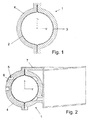
- Fig. 1 shows a section across the cross member 1, on the outside as insulation 4 two insulation shells are attached, one on each one Half shell 2 and 3.
- the outer contour of the cross member 1 corresponds to this essentially the inner contour of the insulation shells.
- the Insulation 4 glued, but other mounting options possible, in particular hang or clipped.
- an clip are in particular undercuts in the form of a dovetail suitable.
- elements are possible, as described in DE 198 02 055 A1 are disclosed.
- the insulation 4 is according to the first embodiment from a foam.
- Fig. 2 are in turn provided as insulation 4 two insulation shells, but they have in contrast to the first embodiment, channels 5, in particular for the passage of cables or air.
- the channels 5 can open the outside, as shown in Fig. 2 on the left, or on the inside, i. Adjacent to the cross member 1, be provided, as shown in Fig. 2 right.
- the channels 5 may have a cover 6, as in FIG Fig. 2 shown top left.
- the channels 5 can, as in Fig. 2 bottom right also be connected to the outside, for example for a Air conditioning and / or ventilation of storage compartments, Cupholder, for one Cooling of DIN slots, a radio, electronic components, etc.
- a pad 7 may be provided on the insulation 4, which For example, as a support for components, such as the instrument panel serve can.
- the insulation 4 according to the second embodiment consists of a particle foam, mainly EPP.
- the third embodiment shown in Fig. 3 is as insulation 4 provided a two-part insulating part instead of the insulation shells, the vehicle interior towards the dashboard 8 forms and the various Fittings absorbs. Further, in the insulating part, the glove box 9 and other subjects provided. Also are the nozzles arranged herein, so that the entire air duct starting from the air conditioning is isolated to the nozzles and thereby the heat loss or the heating and thus the energy consumption are minimized can.
- the insulation 4 according to the third embodiment consists of EPP, on its projecting into the vehicle interior surface with a decorative layer is provided. Such a configuration reduces the number of to be mounted parts considerably. Furthermore, the instrument panel 6 is optimal supported by the directly recorded herein cross member 1.
- the insulation can, for example, as a foam, PU foam without / with Additives, such as mineral foam particles, cork, expanded glass, Pumice, etc. are sprayed.
Landscapes
- Engineering & Computer Science (AREA)
- Mechanical Engineering (AREA)
- Physics & Mathematics (AREA)
- Thermal Sciences (AREA)
- Chemical & Material Sciences (AREA)
- Combustion & Propulsion (AREA)
- Transportation (AREA)
- Air-Conditioning For Vehicles (AREA)
- Body Structure For Vehicles (AREA)
- Cooling, Air Intake And Gas Exhaust, And Fuel Tank Arrangements In Propulsion Units (AREA)
- Motor Or Generator Frames (AREA)
Abstract
Description
- Fig. 1
- einen Schnitt quer durch einen Querträger mit Isolation gemäß dem ersten Ausführungsbeispiel,
- Fig. 2
- einen Schnitt quer durch einen Querträger mit Isolation gemäß dem zweiten Ausführungsbeispiel,
- Fig. 3
- einen Schnitt quer durch eine Instrumententafel mit Querträger gemäß dem dritten Ausführungsbeispiel,
- Fig. 4
- eine perspektivische Ansicht eines Querträgers mit Anbauten ohne Darstellung der Isolation, und
- Fig. 5
- eine andere perspektivische Ansicht des Querträgers von Fig. 4 ohne Isolation.
Claims (11)
- Querträger mit integrierter Luftführung, insbesondere für ein Kraftfahrzeug, wobei eine Isolation (4) vorgesehen ist, dadurch gekennzeichnet, dass die Isolation (4) zumindest benachbart zu einem Teil der Außenfläche des Querträgers (1) angeordnet ist.
- Querträger nach Anspruch 1, dadurch gekennzeichnet, dass die Isolation (4) durch zwei oder mehr Teile gebildet ist.
- Querträger nach Anspruch 1 oder 2, dadurch gekennzeichnet, dass die Isolation (4) mindestens einen Kanal (5) aufweist.
- Querträger nach Anspruch 3, dadurch gekennzeichnet, dass der Kanal (5) ein Kabelkanal oder ein Luftkanal ist.
- Querträger nach Anspruch 3 oder 4, dadurch gekennzeichnet, dass der Kanal (5) auf der Außenfläche der Isolation (4) angeordnet ist.
- Querträger nach einem der Ansprüche 3 bis 5, dadurch gekennzeichnet, dass der Kanal (5) eine Luftführung zur Kühlung eines beabstandet vom Querträger angeordneten Bereichs ist.
- Querträger nach einem der vorhergehenden Ansprüche, dadurch gekennzeichnet, dass die Isolation (4) einstückig mit der Instrumententafel (6) oder einem Teil hiervon gebildet ist.
- Querträger nach einem der vorhergehenden Ansprüche, dadurch gekennzeichnet, dass die Isolation (4) durch einen Schaumstoff, insbesondere einen PU-Schaum, einen Partikelschaum, einen Mineralschaum, gebildet ist.
- Querträger nach einem der vorhergehenden Ansprüche, dadurch gekennzeichnet, dass der Querträger (1) zumindest über Teilbereiche direkt einen Teil des Luftkanals von Klimaanlage zu Ausströmstellen in den Fahrzeuginnenraum bildet.
- Querträger nach einem der vorhergehenden Ansprüche, dadurch gekennzeichnet, dass mindestens ein Luftleitelement vorgesehen ist, welches die von der Klimaanlage kommende Luft in den Querträger (1) einleitet oder aus ihm ausleitet.
- Querträger nach einem der vorhergehenden Ansprüche, dadurch gekennzeichnet, dass die Isolation außen auf den Querträger (1) aufgesprüht, aufgeschäumt, gestrichen, oder in anderer Art und Weise aufgebracht ist.
Applications Claiming Priority (2)
| Application Number | Priority Date | Filing Date | Title |
|---|---|---|---|
| DE102004015086A DE102004015086A1 (de) | 2004-03-25 | 2004-03-25 | Querträger mit integrierter Luftführung für ein Kraftfahrzeug |
| DE102004015086 | 2004-03-25 |
Publications (2)
| Publication Number | Publication Date |
|---|---|
| EP1580048A1 true EP1580048A1 (de) | 2005-09-28 |
| EP1580048B1 EP1580048B1 (de) | 2007-05-02 |
Family
ID=34854089
Family Applications (1)
| Application Number | Title | Priority Date | Filing Date |
|---|---|---|---|
| EP05004848A Expired - Lifetime EP1580048B1 (de) | 2004-03-25 | 2005-03-04 | Querträger mit integrierter Luftführung für ein Kraftfahrzeug |
Country Status (3)
| Country | Link |
|---|---|
| EP (1) | EP1580048B1 (de) |
| AT (1) | ATE361211T1 (de) |
| DE (2) | DE102004015086A1 (de) |
Cited By (2)
| Publication number | Priority date | Publication date | Assignee | Title |
|---|---|---|---|---|
| EP1762469A3 (de) * | 2005-09-07 | 2008-01-02 | Behr GmbH & Co. KG | Querträgeranordnung, insbesondere für ein Kraftfahrzeug |
| DE102010022007A1 (de) | 2010-05-29 | 2010-12-16 | Daimler Ag | Cockpitquerträger für einen Kraftwagen |
Families Citing this family (2)
| Publication number | Priority date | Publication date | Assignee | Title |
|---|---|---|---|---|
| DE102022111874A1 (de) * | 2022-05-12 | 2023-11-16 | Bayerische Motoren Werke Aktiengesellschaft | Verkleidungsteil und Verfahren zur Herstellung eines Verkleidungsteils |
| DE102023113404A1 (de) * | 2023-05-23 | 2024-11-28 | Dr. Ing. H.C. F. Porsche Aktiengesellschaft | Schallisolationsanordnung |
Citations (4)
| Publication number | Priority date | Publication date | Assignee | Title |
|---|---|---|---|---|
| DE7805175U1 (de) * | 1977-03-17 | 1978-06-08 | Automobiles Peugeot, Paris | Armaturenbrett fuer kraftfahrzeuge |
| JPS61160316A (ja) * | 1985-01-09 | 1986-07-21 | Toyota Motor Corp | エアダクト構造 |
| US5234246A (en) * | 1991-05-24 | 1993-08-10 | Ecia | Dashboard |
| US5354114A (en) * | 1993-06-21 | 1994-10-11 | Davidson Textron Inc. | Integrated cross car structural duct cluster |
Family Cites Families (6)
| Publication number | Priority date | Publication date | Assignee | Title |
|---|---|---|---|---|
| DE19753178A1 (de) * | 1997-11-20 | 1999-06-10 | Sommer Allibert Lignotock Gmbh | Cockpit für Kraftfahrzeuge |
| DE19802055A1 (de) * | 1998-01-21 | 1999-07-22 | Behr Gmbh & Co | Gehäuse, insbesondere für eine Heizungs- oder Klimaanlage eines Kraftfahrzeuges |
| DE19917765A1 (de) * | 1999-04-20 | 2000-10-26 | Behr Gmbh & Co | Instrumententafel für ein Kraftfahrzeug |
| DE19938453A1 (de) * | 1999-08-13 | 2001-02-15 | Bayerische Motoren Werke Ag | Luftleitsystem für ein Kraftfahrzeug |
| DE10064522A1 (de) * | 2000-09-07 | 2002-03-21 | Behr Gmbh & Co | Bauteil für ein Kraftfahrzeug |
| DE10221654B4 (de) * | 2001-10-01 | 2005-10-13 | Dura Automotive Plettenberg Entwicklungs- Und Vertriebs Gmbh | Querträger für ein Kraftfahrzeug |
-
2004
- 2004-03-25 DE DE102004015086A patent/DE102004015086A1/de not_active Withdrawn
-
2005
- 2005-03-04 AT AT05004848T patent/ATE361211T1/de not_active IP Right Cessation
- 2005-03-04 EP EP05004848A patent/EP1580048B1/de not_active Expired - Lifetime
- 2005-03-04 DE DE502005000632T patent/DE502005000632D1/de not_active Expired - Lifetime
Patent Citations (4)
| Publication number | Priority date | Publication date | Assignee | Title |
|---|---|---|---|---|
| DE7805175U1 (de) * | 1977-03-17 | 1978-06-08 | Automobiles Peugeot, Paris | Armaturenbrett fuer kraftfahrzeuge |
| JPS61160316A (ja) * | 1985-01-09 | 1986-07-21 | Toyota Motor Corp | エアダクト構造 |
| US5234246A (en) * | 1991-05-24 | 1993-08-10 | Ecia | Dashboard |
| US5354114A (en) * | 1993-06-21 | 1994-10-11 | Davidson Textron Inc. | Integrated cross car structural duct cluster |
Non-Patent Citations (1)
| Title |
|---|
| PATENT ABSTRACTS OF JAPAN vol. 010, no. 365 (M - 542) 6 December 1986 (1986-12-06) * |
Cited By (2)
| Publication number | Priority date | Publication date | Assignee | Title |
|---|---|---|---|---|
| EP1762469A3 (de) * | 2005-09-07 | 2008-01-02 | Behr GmbH & Co. KG | Querträgeranordnung, insbesondere für ein Kraftfahrzeug |
| DE102010022007A1 (de) | 2010-05-29 | 2010-12-16 | Daimler Ag | Cockpitquerträger für einen Kraftwagen |
Also Published As
| Publication number | Publication date |
|---|---|
| DE502005000632D1 (de) | 2007-06-14 |
| EP1580048B1 (de) | 2007-05-02 |
| DE102004015086A1 (de) | 2005-10-13 |
| ATE361211T1 (de) | 2007-05-15 |
Similar Documents
| Publication | Publication Date | Title |
|---|---|---|
| EP0808736B1 (de) | Instrumententafel für ein Kraftfahrzeug | |
| EP1673247B1 (de) | Bauteil, insbesondere hybridträger für ein fahrzeug, und verwendung eines derartigen bauteils | |
| EP1682401B1 (de) | Bauteil, verwendung eines bauteils sowie verfahren zur herstellung eines bauteils, insbesondere eines querträgers für ein fahrzeug | |
| DE69410063T2 (de) | Modularer Spritzwandaufbau für eine Fahrzeugkarosserie | |
| DE19853639C1 (de) | Belüftetes Lenkrad | |
| EP1560724B1 (de) | Querträger in hybridbauweise | |
| WO2002020334A1 (de) | Bauteil für ein kraftfahrzeug | |
| EP1560723B1 (de) | Vorrichtung und verfahren zur luftverteilung in einem fahrzeug | |
| DE10215347A1 (de) | Fahrzeugklimatisierungs-Kanalstruktur, Verfahren zu deren Herstellung und Elektroverkabelungs-Struktur | |
| DE10112688A1 (de) | Vorrichtung zur Verstärkung eines Hohlteils eines Fahrzeugs | |
| EP1673248B1 (de) | Bauteil, insbesondere hybridbauteil für einen querträger eines fahrzeugs und verwendung eines bauteils | |
| EP0808737B1 (de) | Armaturenbrett für ein Kraftfahrzeug | |
| DE29916467U1 (de) | Instrumententräger | |
| DE10064522A1 (de) | Bauteil für ein Kraftfahrzeug | |
| EP1762468B1 (de) | Querträger für ein Kraftfahrzeug | |
| EP3883797B1 (de) | Dachhimmelverkleidung sowie verfahren zur herstellung einer dachhimmelverkleidung | |
| DE102006056366A1 (de) | Strukturell integrierter HVAC-Kanal | |
| EP1732800A1 (de) | Bauteil für einen träger eines fahrzeugs | |
| EP1580048B1 (de) | Querträger mit integrierter Luftführung für ein Kraftfahrzeug | |
| DE102018128997A1 (de) | Halterung für ein Innenverkleidungsteil und Fahrzeugkarosseriestruktur | |
| DE102013013363A1 (de) | Halteanordnung einer Instrumententafel an einem Querträger für einen Kraftwagen | |
| DE102005010161A1 (de) | Bauteil für einen Träger eines Fahrzeugs | |
| DE102017113355B4 (de) | Verfahren zum Herstellen eines Defrostkanals und Defrostkanal | |
| EP1149717A1 (de) | Instrumententafelträger | |
| EP1728659A1 (de) | Querträger mit integrierter Luftführung für ein Kraftfahrzeug |
Legal Events
| Date | Code | Title | Description |
|---|---|---|---|
| PUAI | Public reference made under article 153(3) epc to a published international application that has entered the european phase |
Free format text: ORIGINAL CODE: 0009012 |
|
| AK | Designated contracting states |
Kind code of ref document: A1 Designated state(s): AT BE BG CH CY CZ DE DK EE ES FI FR GB GR HU IE IS IT LI LT LU MC NL PL PT RO SE SI SK TR |
|
| AX | Request for extension of the european patent |
Extension state: AL BA HR LV MK YU |
|
| 17P | Request for examination filed |
Effective date: 20060328 |
|
| AKX | Designation fees paid |
Designated state(s): AT BE BG CH CY CZ DE DK EE ES FI FR GB GR HU IE IS IT LI LT LU MC NL PL PT RO SE SI SK TR |
|
| GRAP | Despatch of communication of intention to grant a patent |
Free format text: ORIGINAL CODE: EPIDOSNIGR1 |
|
| GRAS | Grant fee paid |
Free format text: ORIGINAL CODE: EPIDOSNIGR3 |
|
| GRAA | (expected) grant |
Free format text: ORIGINAL CODE: 0009210 |
|
| AK | Designated contracting states |
Kind code of ref document: B1 Designated state(s): AT BE BG CH CY CZ DE DK EE ES FI FR GB GR HU IE IS IT LI LT LU MC NL PL PT RO SE SI SK TR |
|
| PG25 | Lapsed in a contracting state [announced via postgrant information from national office to epo] |
Ref country code: FI Free format text: LAPSE BECAUSE OF FAILURE TO SUBMIT A TRANSLATION OF THE DESCRIPTION OR TO PAY THE FEE WITHIN THE PRESCRIBED TIME-LIMIT Effective date: 20070502 |
|
| REG | Reference to a national code |
Ref country code: GB Ref legal event code: FG4D Free format text: NOT ENGLISH |
|
| REG | Reference to a national code |
Ref country code: CH Ref legal event code: EP |
|
| REG | Reference to a national code |
Ref country code: IE Ref legal event code: FG4D Free format text: LANGUAGE OF EP DOCUMENT: GERMAN |
|
| REF | Corresponds to: |
Ref document number: 502005000632 Country of ref document: DE Date of ref document: 20070614 Kind code of ref document: P |
|
| REG | Reference to a national code |
Ref country code: SE Ref legal event code: TRGR |
|
| GBT | Gb: translation of ep patent filed (gb section 77(6)(a)/1977) |
Effective date: 20070718 |
|
| PG25 | Lapsed in a contracting state [announced via postgrant information from national office to epo] |
Ref country code: ES Free format text: LAPSE BECAUSE OF FAILURE TO SUBMIT A TRANSLATION OF THE DESCRIPTION OR TO PAY THE FEE WITHIN THE PRESCRIBED TIME-LIMIT Effective date: 20070813 |
|
| PG25 | Lapsed in a contracting state [announced via postgrant information from national office to epo] |
Ref country code: IS Free format text: LAPSE BECAUSE OF FAILURE TO SUBMIT A TRANSLATION OF THE DESCRIPTION OR TO PAY THE FEE WITHIN THE PRESCRIBED TIME-LIMIT Effective date: 20070902 |
|
| ET | Fr: translation filed | ||
| NLV1 | Nl: lapsed or annulled due to failure to fulfill the requirements of art. 29p and 29m of the patents act | ||
| PG25 | Lapsed in a contracting state [announced via postgrant information from national office to epo] |
Ref country code: PL Free format text: LAPSE BECAUSE OF FAILURE TO SUBMIT A TRANSLATION OF THE DESCRIPTION OR TO PAY THE FEE WITHIN THE PRESCRIBED TIME-LIMIT Effective date: 20070502 |
|
| REG | Reference to a national code |
Ref country code: IE Ref legal event code: FD4D |
|
| PG25 | Lapsed in a contracting state [announced via postgrant information from national office to epo] |
Ref country code: BG Free format text: LAPSE BECAUSE OF FAILURE TO SUBMIT A TRANSLATION OF THE DESCRIPTION OR TO PAY THE FEE WITHIN THE PRESCRIBED TIME-LIMIT Effective date: 20070802 Ref country code: IE Free format text: LAPSE BECAUSE OF FAILURE TO SUBMIT A TRANSLATION OF THE DESCRIPTION OR TO PAY THE FEE WITHIN THE PRESCRIBED TIME-LIMIT Effective date: 20070502 Ref country code: CZ Free format text: LAPSE BECAUSE OF FAILURE TO SUBMIT A TRANSLATION OF THE DESCRIPTION OR TO PAY THE FEE WITHIN THE PRESCRIBED TIME-LIMIT Effective date: 20070502 Ref country code: NL Free format text: LAPSE BECAUSE OF FAILURE TO SUBMIT A TRANSLATION OF THE DESCRIPTION OR TO PAY THE FEE WITHIN THE PRESCRIBED TIME-LIMIT Effective date: 20070502 Ref country code: DK Free format text: LAPSE BECAUSE OF FAILURE TO SUBMIT A TRANSLATION OF THE DESCRIPTION OR TO PAY THE FEE WITHIN THE PRESCRIBED TIME-LIMIT Effective date: 20070502 Ref country code: SI Free format text: LAPSE BECAUSE OF FAILURE TO SUBMIT A TRANSLATION OF THE DESCRIPTION OR TO PAY THE FEE WITHIN THE PRESCRIBED TIME-LIMIT Effective date: 20070502 Ref country code: PT Free format text: LAPSE BECAUSE OF FAILURE TO SUBMIT A TRANSLATION OF THE DESCRIPTION OR TO PAY THE FEE WITHIN THE PRESCRIBED TIME-LIMIT Effective date: 20071002 |
|
| PG25 | Lapsed in a contracting state [announced via postgrant information from national office to epo] |
Ref country code: SK Free format text: LAPSE BECAUSE OF FAILURE TO SUBMIT A TRANSLATION OF THE DESCRIPTION OR TO PAY THE FEE WITHIN THE PRESCRIBED TIME-LIMIT Effective date: 20070502 Ref country code: LT Free format text: LAPSE BECAUSE OF FAILURE TO SUBMIT A TRANSLATION OF THE DESCRIPTION OR TO PAY THE FEE WITHIN THE PRESCRIBED TIME-LIMIT Effective date: 20070502 |
|
| PLBE | No opposition filed within time limit |
Free format text: ORIGINAL CODE: 0009261 |
|
| STAA | Information on the status of an ep patent application or granted ep patent |
Free format text: STATUS: NO OPPOSITION FILED WITHIN TIME LIMIT |
|
| 26N | No opposition filed |
Effective date: 20080205 |
|
| PG25 | Lapsed in a contracting state [announced via postgrant information from national office to epo] |
Ref country code: GR Free format text: LAPSE BECAUSE OF FAILURE TO SUBMIT A TRANSLATION OF THE DESCRIPTION OR TO PAY THE FEE WITHIN THE PRESCRIBED TIME-LIMIT Effective date: 20070803 |
|
| PG25 | Lapsed in a contracting state [announced via postgrant information from national office to epo] |
Ref country code: RO Free format text: LAPSE BECAUSE OF FAILURE TO SUBMIT A TRANSLATION OF THE DESCRIPTION OR TO PAY THE FEE WITHIN THE PRESCRIBED TIME-LIMIT Effective date: 20070502 |
|
| PGFP | Annual fee paid to national office [announced via postgrant information from national office to epo] |
Ref country code: SE Payment date: 20080320 Year of fee payment: 4 |
|
| BERE | Be: lapsed |
Owner name: BEHR G.M.B.H. & CO. KG Effective date: 20080331 |
|
| PG25 | Lapsed in a contracting state [announced via postgrant information from national office to epo] |
Ref country code: MC Free format text: LAPSE BECAUSE OF NON-PAYMENT OF DUE FEES Effective date: 20080331 |
|
| PG25 | Lapsed in a contracting state [announced via postgrant information from national office to epo] |
Ref country code: EE Free format text: LAPSE BECAUSE OF FAILURE TO SUBMIT A TRANSLATION OF THE DESCRIPTION OR TO PAY THE FEE WITHIN THE PRESCRIBED TIME-LIMIT Effective date: 20070502 |
|
| PG25 | Lapsed in a contracting state [announced via postgrant information from national office to epo] |
Ref country code: BE Free format text: LAPSE BECAUSE OF NON-PAYMENT OF DUE FEES Effective date: 20080331 |
|
| PG25 | Lapsed in a contracting state [announced via postgrant information from national office to epo] |
Ref country code: CY Free format text: LAPSE BECAUSE OF FAILURE TO SUBMIT A TRANSLATION OF THE DESCRIPTION OR TO PAY THE FEE WITHIN THE PRESCRIBED TIME-LIMIT Effective date: 20070502 |
|
| PG25 | Lapsed in a contracting state [announced via postgrant information from national office to epo] |
Ref country code: AT Free format text: LAPSE BECAUSE OF NON-PAYMENT OF DUE FEES Effective date: 20080304 |
|
| PGFP | Annual fee paid to national office [announced via postgrant information from national office to epo] |
Ref country code: FR Payment date: 20090326 Year of fee payment: 5 |
|
| REG | Reference to a national code |
Ref country code: CH Ref legal event code: PL |
|
| EUG | Se: european patent has lapsed | ||
| GBPC | Gb: european patent ceased through non-payment of renewal fee |
Effective date: 20090304 |
|
| PG25 | Lapsed in a contracting state [announced via postgrant information from national office to epo] |
Ref country code: LI Free format text: LAPSE BECAUSE OF NON-PAYMENT OF DUE FEES Effective date: 20090331 Ref country code: CH Free format text: LAPSE BECAUSE OF NON-PAYMENT OF DUE FEES Effective date: 20090331 |
|
| PG25 | Lapsed in a contracting state [announced via postgrant information from national office to epo] |
Ref country code: GB Free format text: LAPSE BECAUSE OF NON-PAYMENT OF DUE FEES Effective date: 20090304 |
|
| PG25 | Lapsed in a contracting state [announced via postgrant information from national office to epo] |
Ref country code: LU Free format text: LAPSE BECAUSE OF NON-PAYMENT OF DUE FEES Effective date: 20080304 Ref country code: HU Free format text: LAPSE BECAUSE OF FAILURE TO SUBMIT A TRANSLATION OF THE DESCRIPTION OR TO PAY THE FEE WITHIN THE PRESCRIBED TIME-LIMIT Effective date: 20071103 |
|
| PG25 | Lapsed in a contracting state [announced via postgrant information from national office to epo] |
Ref country code: TR Free format text: LAPSE BECAUSE OF FAILURE TO SUBMIT A TRANSLATION OF THE DESCRIPTION OR TO PAY THE FEE WITHIN THE PRESCRIBED TIME-LIMIT Effective date: 20070502 |
|
| PGFP | Annual fee paid to national office [announced via postgrant information from national office to epo] |
Ref country code: DE Payment date: 20100323 Year of fee payment: 6 |
|
| REG | Reference to a national code |
Ref country code: FR Ref legal event code: ST Effective date: 20101130 |
|
| PG25 | Lapsed in a contracting state [announced via postgrant information from national office to epo] |
Ref country code: FR Free format text: LAPSE BECAUSE OF NON-PAYMENT OF DUE FEES Effective date: 20100331 |
|
| PG25 | Lapsed in a contracting state [announced via postgrant information from national office to epo] |
Ref country code: SE Free format text: LAPSE BECAUSE OF NON-PAYMENT OF DUE FEES Effective date: 20090305 |
|
| PGFP | Annual fee paid to national office [announced via postgrant information from national office to epo] |
Ref country code: IT Payment date: 20080331 Year of fee payment: 4 |
|
| PG25 | Lapsed in a contracting state [announced via postgrant information from national office to epo] |
Ref country code: DE Free format text: LAPSE BECAUSE OF NON-PAYMENT OF DUE FEES Effective date: 20111001 |
|
| REG | Reference to a national code |
Ref country code: DE Ref legal event code: R119 Ref document number: 502005000632 Country of ref document: DE Effective date: 20111001 |