EP1579994A1 - Printing machine with an inline inspection system - Google Patents
Printing machine with an inline inspection system Download PDFInfo
- Publication number
- EP1579994A1 EP1579994A1 EP05102011A EP05102011A EP1579994A1 EP 1579994 A1 EP1579994 A1 EP 1579994A1 EP 05102011 A EP05102011 A EP 05102011A EP 05102011 A EP05102011 A EP 05102011A EP 1579994 A1 EP1579994 A1 EP 1579994A1
- Authority
- EP
- European Patent Office
- Prior art keywords
- printing
- machine according
- printing machine
- light source
- light
- Prior art date
- Legal status (The legal status is an assumption and is not a legal conclusion. Google has not performed a legal analysis and makes no representation as to the accuracy of the status listed.)
- Granted
Links
- 238000007639 printing Methods 0.000 title claims abstract description 200
- 238000007689 inspection Methods 0.000 title claims abstract description 109
- 239000000463 material Substances 0.000 claims abstract description 102
- 239000002826 coolant Substances 0.000 claims abstract description 44
- 238000001816 cooling Methods 0.000 claims abstract description 23
- 239000007788 liquid Substances 0.000 claims abstract description 8
- 238000005286 illumination Methods 0.000 claims description 87
- 238000000034 method Methods 0.000 claims description 30
- 238000012545 processing Methods 0.000 claims description 25
- 230000008569 process Effects 0.000 claims description 24
- 238000005259 measurement Methods 0.000 claims description 10
- 239000000758 substrate Substances 0.000 claims description 10
- XLYOFNOQVPJJNP-UHFFFAOYSA-N water Substances O XLYOFNOQVPJJNP-UHFFFAOYSA-N 0.000 claims description 6
- 239000004020 conductor Substances 0.000 claims description 5
- 230000008878 coupling Effects 0.000 claims description 5
- 238000010168 coupling process Methods 0.000 claims description 5
- 238000005859 coupling reaction Methods 0.000 claims description 5
- 230000001154 acute effect Effects 0.000 claims description 2
- 238000009529 body temperature measurement Methods 0.000 claims description 2
- 238000011144 upstream manufacturing Methods 0.000 claims description 2
- 230000001012 protector Effects 0.000 claims 1
- 230000001360 synchronised effect Effects 0.000 claims 1
- 238000013016 damping Methods 0.000 abstract 2
- 238000001514 detection method Methods 0.000 description 26
- 239000000976 ink Substances 0.000 description 25
- 230000003287 optical effect Effects 0.000 description 21
- 238000004519 manufacturing process Methods 0.000 description 19
- 230000005855 radiation Effects 0.000 description 17
- 230000008901 benefit Effects 0.000 description 15
- 239000000123 paper Substances 0.000 description 15
- 230000006870 function Effects 0.000 description 12
- 239000007787 solid Substances 0.000 description 10
- 239000003086 colorant Substances 0.000 description 8
- 230000007547 defect Effects 0.000 description 7
- 230000008859 change Effects 0.000 description 6
- 238000010586 diagram Methods 0.000 description 6
- 238000011156 evaluation Methods 0.000 description 6
- 238000007645 offset printing Methods 0.000 description 6
- 238000012546 transfer Methods 0.000 description 6
- 238000004458 analytical method Methods 0.000 description 5
- 230000001419 dependent effect Effects 0.000 description 5
- 238000005496 tempering Methods 0.000 description 5
- 230000006399 behavior Effects 0.000 description 4
- 239000003973 paint Substances 0.000 description 4
- 230000000694 effects Effects 0.000 description 3
- 238000012544 monitoring process Methods 0.000 description 3
- 238000001454 recorded image Methods 0.000 description 3
- 230000035945 sensitivity Effects 0.000 description 3
- 238000000926 separation method Methods 0.000 description 3
- 230000009466 transformation Effects 0.000 description 3
- 230000001960 triggered effect Effects 0.000 description 3
- 102100027765 Atlastin-2 Human genes 0.000 description 2
- 101710192135 Atlastin-2 Proteins 0.000 description 2
- 238000012935 Averaging Methods 0.000 description 2
- 102100026064 Exosome complex component RRP43 Human genes 0.000 description 2
- 101001055989 Homo sapiens Exosome complex component RRP43 Proteins 0.000 description 2
- 230000009471 action Effects 0.000 description 2
- 230000006978 adaptation Effects 0.000 description 2
- 238000004422 calculation algorithm Methods 0.000 description 2
- 239000011248 coating agent Substances 0.000 description 2
- 238000000576 coating method Methods 0.000 description 2
- 230000004456 color vision Effects 0.000 description 2
- 238000004040 coloring Methods 0.000 description 2
- 238000004891 communication Methods 0.000 description 2
- 238000010276 construction Methods 0.000 description 2
- 238000011109 contamination Methods 0.000 description 2
- 238000009826 distribution Methods 0.000 description 2
- 230000010354 integration Effects 0.000 description 2
- 238000007726 management method Methods 0.000 description 2
- 238000002156 mixing Methods 0.000 description 2
- BASFCYQUMIYNBI-UHFFFAOYSA-N platinum Chemical compound [Pt] BASFCYQUMIYNBI-UHFFFAOYSA-N 0.000 description 2
- 230000001105 regulatory effect Effects 0.000 description 2
- 238000012549 training Methods 0.000 description 2
- LFQSCWFLJHTTHZ-UHFFFAOYSA-N Ethanol Chemical compound CCO LFQSCWFLJHTTHZ-UHFFFAOYSA-N 0.000 description 1
- 241000237858 Gastropoda Species 0.000 description 1
- 101000650160 Homo sapiens NEDD4-like E3 ubiquitin-protein ligase WWP2 Proteins 0.000 description 1
- 102100027549 NEDD4-like E3 ubiquitin-protein ligase WWP2 Human genes 0.000 description 1
- 229910000831 Steel Inorganic materials 0.000 description 1
- 241000482270 Tandonia budapestensis Species 0.000 description 1
- 239000004904 UV filter Substances 0.000 description 1
- 210000001015 abdomen Anatomy 0.000 description 1
- 238000005299 abrasion Methods 0.000 description 1
- 230000004913 activation Effects 0.000 description 1
- 230000003044 adaptive effect Effects 0.000 description 1
- 239000000654 additive Substances 0.000 description 1
- 230000032683 aging Effects 0.000 description 1
- 229910052782 aluminium Inorganic materials 0.000 description 1
- XAGFODPZIPBFFR-UHFFFAOYSA-N aluminium Chemical compound [Al] XAGFODPZIPBFFR-UHFFFAOYSA-N 0.000 description 1
- 238000000149 argon plasma sintering Methods 0.000 description 1
- 230000001174 ascending effect Effects 0.000 description 1
- 238000003705 background correction Methods 0.000 description 1
- 230000009286 beneficial effect Effects 0.000 description 1
- 230000005540 biological transmission Effects 0.000 description 1
- 238000007664 blowing Methods 0.000 description 1
- 238000004364 calculation method Methods 0.000 description 1
- 238000006243 chemical reaction Methods 0.000 description 1
- 238000010367 cloning Methods 0.000 description 1
- 238000004737 colorimetric analysis Methods 0.000 description 1
- 150000001875 compounds Chemical class 0.000 description 1
- 238000005094 computer simulation Methods 0.000 description 1
- 230000003750 conditioning effect Effects 0.000 description 1
- 230000001276 controlling effect Effects 0.000 description 1
- 238000012937 correction Methods 0.000 description 1
- 125000004122 cyclic group Chemical group 0.000 description 1
- 230000003247 decreasing effect Effects 0.000 description 1
- 230000002950 deficient Effects 0.000 description 1
- 238000009795 derivation Methods 0.000 description 1
- 238000013461 design Methods 0.000 description 1
- 238000007599 discharging Methods 0.000 description 1
- 238000006073 displacement reaction Methods 0.000 description 1
- 239000000428 dust Substances 0.000 description 1
- 238000004043 dyeing Methods 0.000 description 1
- 238000004049 embossing Methods 0.000 description 1
- 229910052736 halogen Inorganic materials 0.000 description 1
- 150000002367 halogens Chemical class 0.000 description 1
- 238000000265 homogenisation Methods 0.000 description 1
- 238000010191 image analysis Methods 0.000 description 1
- 230000001771 impaired effect Effects 0.000 description 1
- 238000009434 installation Methods 0.000 description 1
- 238000011835 investigation Methods 0.000 description 1
- 238000011068 loading method Methods 0.000 description 1
- 239000011159 matrix material Substances 0.000 description 1
- 229910052751 metal Inorganic materials 0.000 description 1
- 239000002184 metal Substances 0.000 description 1
- 239000002245 particle Substances 0.000 description 1
- 230000008447 perception Effects 0.000 description 1
- 230000001766 physiological effect Effects 0.000 description 1
- 238000007781 pre-processing Methods 0.000 description 1
- 239000002243 precursor Substances 0.000 description 1
- 238000003825 pressing Methods 0.000 description 1
- 238000004080 punching Methods 0.000 description 1
- 238000000275 quality assurance Methods 0.000 description 1
- 238000003908 quality control method Methods 0.000 description 1
- 238000013139 quantization Methods 0.000 description 1
- 230000004044 response Effects 0.000 description 1
- 230000002441 reversible effect Effects 0.000 description 1
- 238000007650 screen-printing Methods 0.000 description 1
- 239000004065 semiconductor Substances 0.000 description 1
- -1 sheet Substances 0.000 description 1
- 230000006641 stabilisation Effects 0.000 description 1
- 238000011105 stabilization Methods 0.000 description 1
- 238000010972 statistical evaluation Methods 0.000 description 1
- 239000010959 steel Substances 0.000 description 1
- 238000003860 storage Methods 0.000 description 1
- QERYCTSHXKAMIS-UHFFFAOYSA-M thiophene-2-carboxylate Chemical compound [O-]C(=O)C1=CC=CS1 QERYCTSHXKAMIS-UHFFFAOYSA-M 0.000 description 1
- 238000000844 transformation Methods 0.000 description 1
- 238000001665 trituration Methods 0.000 description 1
- 230000000007 visual effect Effects 0.000 description 1
- 238000010792 warming Methods 0.000 description 1
- 239000002699 waste material Substances 0.000 description 1
- 230000037303 wrinkles Effects 0.000 description 1
Images


Classifications
-
- B—PERFORMING OPERATIONS; TRANSPORTING
- B41—PRINTING; LINING MACHINES; TYPEWRITERS; STAMPS
- B41F—PRINTING MACHINES OR PRESSES
- B41F33/00—Indicating, counting, warning, control or safety devices
- B41F33/0036—Devices for scanning or checking the printed matter for quality control
-
- G—PHYSICS
- G01—MEASURING; TESTING
- G01J—MEASUREMENT OF INTENSITY, VELOCITY, SPECTRAL CONTENT, POLARISATION, PHASE OR PULSE CHARACTERISTICS OF INFRARED, VISIBLE OR ULTRAVIOLET LIGHT; COLORIMETRY; RADIATION PYROMETRY
- G01J3/00—Spectrometry; Spectrophotometry; Monochromators; Measuring colours
- G01J3/02—Details
- G01J3/10—Arrangements of light sources specially adapted for spectrometry or colorimetry
-
- G—PHYSICS
- G01—MEASURING; TESTING
- G01N—INVESTIGATING OR ANALYSING MATERIALS BY DETERMINING THEIR CHEMICAL OR PHYSICAL PROPERTIES
- G01N21/00—Investigating or analysing materials by the use of optical means, i.e. using sub-millimetre waves, infrared, visible or ultraviolet light
- G01N21/84—Systems specially adapted for particular applications
- G01N21/88—Investigating the presence of flaws or contamination
- G01N21/8806—Specially adapted optical and illumination features
-
- G—PHYSICS
- G01—MEASURING; TESTING
- G01N—INVESTIGATING OR ANALYSING MATERIALS BY DETERMINING THEIR CHEMICAL OR PHYSICAL PROPERTIES
- G01N21/00—Investigating or analysing materials by the use of optical means, i.e. using sub-millimetre waves, infrared, visible or ultraviolet light
- G01N21/84—Systems specially adapted for particular applications
- G01N21/88—Investigating the presence of flaws or contamination
- G01N21/89—Investigating the presence of flaws or contamination in moving material, e.g. running paper or textiles
-
- G—PHYSICS
- G01—MEASURING; TESTING
- G01J—MEASUREMENT OF INTENSITY, VELOCITY, SPECTRAL CONTENT, POLARISATION, PHASE OR PULSE CHARACTERISTICS OF INFRARED, VISIBLE OR ULTRAVIOLET LIGHT; COLORIMETRY; RADIATION PYROMETRY
- G01J3/00—Spectrometry; Spectrophotometry; Monochromators; Measuring colours
- G01J3/02—Details
- G01J3/0286—Constructional arrangements for compensating for fluctuations caused by temperature, humidity or pressure, or using cooling or temperature stabilization of parts of the device; Controlling the atmosphere inside a spectrometer, e.g. vacuum
-
- G—PHYSICS
- G01—MEASURING; TESTING
- G01N—INVESTIGATING OR ANALYSING MATERIALS BY DETERMINING THEIR CHEMICAL OR PHYSICAL PROPERTIES
- G01N21/00—Investigating or analysing materials by the use of optical means, i.e. using sub-millimetre waves, infrared, visible or ultraviolet light
- G01N21/84—Systems specially adapted for particular applications
- G01N21/88—Investigating the presence of flaws or contamination
- G01N21/89—Investigating the presence of flaws or contamination in moving material, e.g. running paper or textiles
- G01N21/8914—Investigating the presence of flaws or contamination in moving material, e.g. running paper or textiles characterised by the material examined
- G01N2021/8917—Paper, also ondulated
-
- G—PHYSICS
- G01—MEASURING; TESTING
- G01N—INVESTIGATING OR ANALYSING MATERIALS BY DETERMINING THEIR CHEMICAL OR PHYSICAL PROPERTIES
- G01N2201/00—Features of devices classified in G01N21/00
- G01N2201/06—Illumination; Optics
- G01N2201/061—Sources
- G01N2201/06113—Coherent sources; lasers
- G01N2201/0612—Laser diodes
Definitions
- the invention relates to printing presses with an in-line inspection system according to the The preamble of claim 1, 4 or 9.
- the application consists primarily in the evaluation of a quality one of a Printing machine produced printed matter, the printing machine preferably as a rotary printing machine, in particular as one in an offset printing method, in a steel engraving process, in a screen printing process or in a Hot embossing process printing press is formed.
- DE 41 02 122 A1 is suitable for use in the printing industry Method for the examination of sheet-like, translucent material, in particular a paper web, known in the z. B. with LEDs or Laser diodes realized flash lamps shine through a paper web, in which the paper web radiating light for generating a video signal on a CCD matrix a camera falls.
- From DE 43 21 177 A1 is a printing machine with an inline image inspection device for inspection of a machine created in the printing press Print product known, wherein an image data from the printed product to a Computing device providing image capture device is provided, wherein the Image capture device from one measurement module or several each one defined Image area of the printed product scanning measuring modules and at least one associated, the image data in electrical form providing and preferably of the measuring modules spatially separated receiving device, wherein the Measuring modules and the at least one receiving device by means of at least one Image guide are connected to each other, wherein the image capture device from a Precision halogen lamps is associated with existing lighting device, wherein a Blasluftrohr with openings in the direction of the printed product at his Blas Kunststoffbeierschlagung the printed product at a defined distance from Lighting device holds and at the same time with the blowing air, the lighting device cools.
- a lighting device for an optical Inspection device for the investigation of surfaces known, with several preferably the same length, electrically interconnected carrier boards, each with several rows of light emitting diodes linearly in a common, according to the elongated with a constant light emission scanned object surface, stiff Mounting profile are inserted, wherein between the carrier boards and the Mounting profile via a mechanical connection a heat coupling for cooling the Light-emitting diodes and their control electronics takes place.
- DE 203 03 574 U1 is an inline image inspection system for a printing press, in particular a sheet-fed offset printing machine, one known as one Fluorescent lamp formed lighting device below a kick close on a printing material leading impression cylinder and one as a Line scan camera formed image recording device in a compared to Lighting device further distance from the impression cylinder in an assignment is arranged to the last printing unit of the printing press.
- a Print press in particular a sheet-fed offset printing machine
- Fluorescent lamp formed lighting device below a kick close on a printing material leading impression cylinder and one as a Line scan camera formed image recording device in a compared to Lighting device further distance from the impression cylinder in an assignment is arranged to the last printing unit of the printing press.
- EP 0 762 174 A2 discloses a device for linear illumination of Sheet material, such as. As banknotes or securities, known, wherein a cylindrical mirror is provided with two mirror segments, the mirror segments being an elliptical, form two focal lines having footprint, the width of the Mirror segments greater than or equal to the width of the sheet material is selected, wherein in the first focus line that of a transport device perpendicular to this focus line transported sheet material and in the second focus line a cold light source, eg. B. a number of light emitting diodes (LED's) is arranged, wherein a detector, for. B. a CCD array or individually or in groups arranged photodiodes, the remitted from the sheet material light recorded and converted into signals for processing in a processing plant.
- a cold light source eg. B. a number of light emitting diodes (LED's) is arranged, wherein a detector, for. B. a CCD array or individually or in groups arranged photodiodes
- US 5,936,353 is an optical system for generating a lit. Formed on a surface of a material moving relative to the structure, wherein a lighting device with a plurality of light sources generates light for generating the Formed emitted, wherein a detection device with at least one detector of the light reflected on the surface of the material, the light sources on a Board are arranged, wherein the circuit board is arranged on a support, wherein the Carrier has in its interior at least one channel, wherein a liquid or gaseous cooling medium for cooling the light sources flows through the channel. Measures to achieve a constant light intensity arranged on the support Light sources are not described.
- the invention is based on the object printing presses with an inline inspection system to accomplish.
- the Printing machine has an inline inspection system with a lighting device, wherein the light source of the illumination device, despite its own warming or light external heat influences due to a cooling of their light source with a high Constance radiates.
- a constant light emission is required to make one in her Print process inspected to reliably assess their quality can, because a change or fluctuation in the light emission can lead to a Misinterpretation of the image data taken from the printed matter and thus to a improper intervention in the printing process.
- the proposed solution has the advantage that the thermal load of the light source dissipated directly at the point of origin , resulting in short control times to maintain a constant light emission achieve. Also can be with the proposed measures a high Reach light output.
- the material on the surface thereof illuminated entity is to generate, not in a direct or in the deflected Beam path lying focal point of the light emitted by the light sources must be arranged to the structure in a sufficient illuminance to appear.
- An independent of the focus arrangement of the structure relative to his optical system is advantageous, because then to an exact dimensional accuracy with respect to the distance between the structure and the illumination device can be waived.
- the described optical system is therefore for illuminated material distance tolerant. It is also between components of the optical system caused by contamination, eg. B.
- a illuminated by the lighting device lighting strip with a on the surface of the material orthogonal to its length extending width, d. H. on two-dimensional, flat structure, has opposite to a focus focused linear, d. H. only one-dimensional, illuminated entities have the advantage that the illuminated structure for a reflective to the surface of the at least partially Material arranged under a reflection angle detecting means for detection of the light remitted from the surface of the material even in a relief-like Design of the surface of the material reliably as a virtual line-shaped Lighting device appears because due to the width of the lighting strip it is ensured that one is present on the surface of the material Cross sectional area of a detection angle of the detection device, in which the Detecting device to detect reflected light is able to at least part of a over the width of the illumination strip extending cross-sectional area of detected light beam emitted by the illumination device.
- the described optical system is also for a Image capture of material with a diffuse reflective surface well suited. Even in the case of a material with a relief-like surface, hardly any shadowing effect occurs.
- the lighting device of the in-line inspection system is preferably in modules, d. H. in separate functional units, built, which has the advantage that a Line length of the line-shaped lighting device without expensive custom-made by simply juxtaposing prefabricated, preferably functionally identical Modules in the required number to the width of the material to be illuminated or is adaptable at least to the length of the illumination strip.
- the light sources are activated only in those modules, to illuminate the width of the material to be illuminated or at least the length of the lighting strip are needed, which in the construction and operation of the optical system for its economy is beneficial.
- each Module preferably a plurality of groups of light sources are arranged, wherein the distinguish the light sources assigned to the groups in their optical properties, z. In the color of the light emitted by the light sources of each group, can the individual groups of light sources application-dependent, z. B. after Color of light to be selected and controlled.
- the lighting device of the in-line inspection system has the advantage of being a possibly a long length of z. B. over one meter Lighting strips by a uniform, needs-based light distribution with a homogeneous, sufficiently large illuminance applied and by his modular, low failure prone structure in a simple way to the respective Requirements in a printing machine is customizable. Because the material to be illuminated is not to be placed in a focal point of the lighting device, also eliminates the Need for an exact alignment of the vertical distance of the light sources to the surface of the material as well as a monitoring of this distance during the ongoing use of the optical system, resulting in the handling of the optical Systems suburb in an industrial plant greatly simplified.
- Fluctuation ranges is a color determination and inspection that requires the typical Fluctuations in the quality of the printed matter produced. To call are here permitted color variations, positional shifts of the subject or displacements of objects within a creative. Furthermore, it has to be considered that i. a. certain areas of the template are inspectable while others are not.
- the in-line inspection system described here for assessing a quality of a a printed matter produced has at least one Image pickup unit, in particular a camera, preferably a Color line camera system, on.
- the color line camera system preferably uses a color line camera with up to 2048 pixels per image line.
- the inline inspection system to assess the quality of the produced by the printing press Printed matter is included for inline inspection and inline color control Medium format machines (Perfecting) designed.
- Inline inspection means that one Substrate is inspected during its transport through the press.
- the Inline inspection system ensures that operator-defined quality during the entire production process.
- the inline inspection system to assess the quality of the press produced printed matter consists essentially of three components: at least an image pickup unit, a camera and lighting electronics unit and a Control cabinet with an image processing system.
- the image pickup unit is installed in the printing machine. It has z. Legs Color line camera, a constant light illumination or alternatively one Flash lighting, in particular a triggered line lighting, on, both the constant light illumination as well as the flashlight illumination in each case several next to each other, d. H. have line-shaped, arranged light sources, wherein the Lighting device each z. B. is cooled with water, and a rotary encoder, wherein the encoder z. B. has a resolution of 10,000 strokes.
- Cylinders associated with this printing machine each have an image pickup unit, wherein at least one image recording unit, in particular a camera, in front of a Turning device for a sheet to be printed in the printing press and a another image recording unit, in particular a further camera, after this Turning device are arranged behind the last printing unit of the printing press.
- the Signals of the two image recording units are z. From the same Image processing system processed in a duplex mode and evaluated.
- the camera and lighting electronics unit includes all necessary Function units for power supply of the lighting unit and the Signal conditioning of the camera.
- This unit will be near the image acquisition unit housed in a suitable location. It provides a homogeneous illumination of the safely transported through the printing press. With the help of a light measuring function during the engine run z. B. checked cyclically, if the bulbs flawless, d. H. work in their designated workspace.
- the cabinet with the image processing system includes in particular z. Legs Power supply of the image processing system and an image processing computer preferably including an interface for operation to a control room computer (TCP / IP) as well as the connection possibility of a monitor, z.
- TCP / IP control room computer
- a user interface can temporarily on a second PC, before the operating software for a series product in one the printing machine associated control station is integrated.
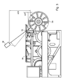
- the camera and lighting unit is z. B. in a in Fig. 1 shown Sheet-fed offset printing machine, z. B. a five-color printing machine with a Printing units downstream coating tower and a delivery extension, installed.
- a existing chain guide in the ascending branch of a chain run stabilizes one in the Printing press transported sheets during a learning and inspection process.
- Fig. 1 shows a sheetfed offset press alone for the Perfecting.
- the inspection of the printing material is performed by the Inline inspection system to assess the quality of one of the printing press produced printed matter z. B. on in the production process last printing unit in the Production process preferably sequentially several printing units have Printing press or on the printing units downstream paint tower.
- an image recording z. B. with a 3-chip color CCD line scan camera with z. B. 2048 pixels performed. It is ensured that the entire arc during a maximum machine speed of z. B. 18,000 sheets / h can be inspected.
- the printing machine is designed as a web-fed printing press, a material web, for. B. a paper web, even at a maximum machine speed of z. For example, to reliably inspect 15 m / s.
- the resolution is z. B. about 0.25 mm 2 per pixel at a pixel edge length of z. B. about 0.5 mm.
- Lighting device 06 preferably generates a lighting strip 01 a transported from the printing cylinder 39 bow. It is the Lighting device 06 preferably within a part of the printing of the Printing machine surrounding protection 38, z. B. below a foot 38 in the Gallery area of the printing press arranged.
- Remitted from the lighting strip 01 Light is emitted from a camera 08 arranged at a distance from the printing cylinder 39; 201 detected within a certain detection angle ⁇ .
- the camera 08; 201 recorded from the illumination strip 01 remitted light preferably by a preferably narrow gap or slot in the pressure cylinder 38 covering the protection 38th or foot 38, wherein this gap or slot transverse to the transport direction of the Substrate extends.
- the image processing system consists z. B. from a VMEbus rack with z. As a whole six plug-in cards. In addition to a CPU (PowerPC, real-time operating system OS9), one Frame grabber for image acquisition and image data preprocessing as well as a graphics card for Image display and error display are z. B. three image processing cards for learning and the inspection of the sheet present.
- a CPU PowerPC, real-time operating system OS9
- the system is z. B. by means of an Ethernet interface with a control computer, the Operating PC, d. H. z. B. either an external PC or a control desk computer, networked. All the settings required for the inspection and inspection will be displayed on the control PC Color control necessary.
- the operating software is preferably under running on all current Microsoft operating systems.
- the operating computer can be connected to external data networks, so that Repeat orders from a central database and possibly data from the Prepress, e.g. from a CIP3 station.
- a control of the ink zone adjustment in the inking unit of the respective printing units takes place for.
- ARCNet By means of ARCNet.
- the VMEbus CPU is equipped with an ARCNet card.
- the so-called fault monitor connected to the graphics card of the image processing system.
- This shows a live picture of the camera.
- the misprint display is in the Camera image is displayed, so that the operator is immediately able, the fault location and if necessary, localize the cause of the error.
- the fault monitor shows both the substrate short-term printing errors, eg. B. splashes of paint, water spots or paper defects, as well as permanent pressure deviations, z. B. an over- or Undercolouring of single inks or a toning, on.
- a process learning mode is integrated, which is able to to automatically learn the current quality standard during the good production.
- the Programming a model is not necessary.
- References are generated especially for the color model and the intensity model. which are used for comparison for inspection and color determination.
- the Learning mode includes in particular the following functions: learning references, Extend learned or saved references, entering the number of desired ones Learning arc, defining the window of the inspection area, showing the learned or stored reference image, input of the mask for a non-inspected image area, Editing the reference image, editing and copying masks.
- the inline inspection system is capable of permissible changes in the Continuous pressure, which is considered by the inline inspection system as a fault, while running To learn about production.
- the inline inspection system adapts adaptively to the current quality standard and controls or regulates z.
- the human eye is able to detect relatively small color changes.
- human color perception is based on the detection of surfaces designed. Small punctiform color changes are not detected.
- the Color analysis model takes into account this physiological effect. It will be the Color space of the camera spanning colors red, green and blue in a color space transformed, which is referred to as Martinezticianmodell.
- the counter-color model corresponds to an electronic adjustment of human color perception. therein There are two reverse color channels that are extremely sensitive to color changes react. In particular, a tilt of the gray balance of these channels reliably detected.
- the counter-ink model can also be based on the offset printing inks CMYK be implemented, this color model compared to the sensible Color model is aligned to a subtractive color mixing (printing process).
- Intensity deviations d. H. Changes in color density, are over a Gray value analysis detected. This method has particular in areas undone Colors, in a over- and under-coloring as well as small errors, z. B. small Color splashes or paper defects, its strengths.
- a color scheme may vary depending on the conditions in the specific case done by two different methods. If colorimeter with sufficient large color fields are present, according to the scheme for color density control with a color measuring strip in FIG. 6, first the nominal densities for the individual Colors entered. The position of the measuring control strip is determined by the operator Monitor marked. After that, the fields of the strip are automatically related to Scales colors analyzed and determines the actual density. Special colors are from Mark the operator in the measuring strip. Based on the deviations from a nominal density and the actual density present, the ink zones on an inking the Printing machine provided. The respective deviations become graphic and numerical displayed. The inline inspection system proposes default values for the Color zone position indicated. These can either be adopted manually or Fully automatically used in closed loop. With the help of Color measurement strips can also be used to determine dot gain with the help of the grid fields become.
- the density determination algorithms in colorimeters can be used for each arc to go through. Also a moving averaging of the measured values over one any number of sheets is possible. Measurement inaccuracies caused by the influence of Fluctuations in pressure due to camera noise, eg. B. a photon noise or a quantization noise of the AD converter, or by an instability of The amount of light emitted by the illumination device is produced on it Way reliably eliminated or at least minimized in their interference.
- camera noise eg. B. a photon noise or a quantization noise of the AD converter
- Calibration of the density measuring system is carried out with measuring sheets, which are regularly Travels are driven through the machine.
- calibrating becomes automatic a color balance, a contrast and a brightness adjusted.
- the standard light be set for the measurement, z. B. as usual D50 or D65.
- a re-calibration is usually not needed more often than once a week in practice.
- the measuring strip has a field width and a field height in each case z. B. from about 5 mm to 6 mm.
- the field size required by a 2 ° standard observer must be in the field of view be safely accommodated.
- the measuring strip consists of several identical ones Segments, with a regular structure within a segment.
- Another method of color control as shown by a diagram in FIG. 7, a color determination and color control based on the printed image before. requirement this is because the area coverage per ink with a resolution of 10 ⁇ dpi ⁇ 40 from a preliminary stage, z. CIP3, and that "significant" pressure ranges per Color zone or ink zone area are present. Significant are pressure ranges then, when one of the inks in this area is dominant. The determination of Significant pressure ranges occur automatically by evaluating data from the Precursor.
- the color determination and the derivation of manipulated variables for the color control takes place on the basis of the print image itself.
- a transformation of the camera image data in carried out the CMYK room.
- the analysis of the printed image is based on a color integration of the significant Pressure ranges within longitudinal strips, in number, preferably the number correspond to the zone screws. These strips are again divided horizontally. Within these resulting surfaces is determined by the color changes and the Zone density set the appropriate zone. By appropriate averaging over several sheets are compensated for permissible process fluctuations.
- a colorimetric error calculated from the measurement is calculated for each Color zone in a control command to control the relevant zone screw implemented.
- a change in the ink supply within the press takes a certain amount of time, before it becomes visible in the print image. This behavior is due to the nature of Color transfer justified in the printing press.
- a controller as an integral controller with a proportional component, short PI controller, intended.
- This controller has the advantage that in addition to a stationary component (I component) for a certain time an error proportional share for one provides additional / reduced ink supply and thus speeds up the control process.
- the additional or reduced ink supply caused by the proportional component is simplified for a certain time, i. H. for a certain number of Cylinder revolutions, approved. After this time, all the color zones will open moved to the stationary state.
- control loop is simplified in that a cyclic method with the steps of measuring, setting and waiting is realized. After completion of the waiting period, d. H. after a certain number of cylinder revolutions, will come with a new one Measurement started a new cycle. So it is despite the closed Control loop around an open principle of action, since the relevant time constant by the time between position of the zones and a reaction on the paper is fixed. There this time z. B. is proportional to some ten sheets, here is an open Realized principle of action. Furthermore, the scheme itself as a position control executed, d. H. the opening of each zone is set and for a certain time held in this position. To achieve the target density as quickly as possible, is admitted that in the case of a paint supply the zones may be for a certain time be overruled.
- the control algorithm integrates all parameters influencing the color scheme. These include in particular the color behavior, d. H. a cover of color that Paper behavior and the ink transfer behavior of the ink fountain. Here are the Color and the paper order-dependent parameters.
- the change in ink supply in a color zone is due to the trituration of the color
- the color transfer within the printing unit also affects their Neighboring zones. To take this effect into account, the neighboring ones Color zones to a certain extent proportionally to the adjusted color zone mitver reinstate.
- this adjustment can be further Neighboring zones. Any adjustment of a color zone, be it automatic or manually, "generates" new target values for the neighboring zones.
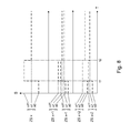
- each color zone is limited. If a zone is more than "completely open” can be adjusted, additional color only by changing the strip length the ductor of the inking unit can be achieved. A change in the strip length on the Ductor increases the ink supply in all ink zones. In this case, the ink supply for the color zone concerned either limited or the additional ink supply Changing the strip length must be done at the other color zones by closing all other color zones are compensated. Becomes the lower limit of zone adjustment achieved, namely, when a color zone is closed, no further compensation possible. If the upper limit is reached for a color zone or must it be for the stationary state are exceeded, then in any case, the strip length on to change the ductor, and all other color zones should be adjusted accordingly it reveals the diagram of FIG.
- the preferably digitally working image recording unit comprises z. B. a specially for the sheetfed lighting unit developed and a color CCD line scan camera.
- the Lens is specially adapted to the high-resolution camera, has a removable Filter, e.g. B. a UV filter as a lens protection and can be adjusted user-friendly become. When servicing, the camera and the lens can be easily replaced.
- the image acquisition unit is against mechanical and electromagnetic interference protected.
- the arrangement of the bulbs within the lighting unit is z. B. especially for application in sheetfed printing customized. The bulbs can be easily exchanged.
- the image capture module sets the incoming video image into one digital video stream around.
- This video stream becomes one in the frame grabber Brightness adjustment (shading correction), a perception-oriented Color matching and color space transformation subjected.
- This digital video stream is stored in the memory area of the image acquisition module for later processing.
- the Image acquisition and image analysis is performed in machine real-time.
- the inline inspection system is z. B. equipped with a positioning unit, the in is able to perform an image positioning. By blurring in the Transport movement of the sheet may be necessary, the recorded image for each image in the in-line inspection system. During the The learning process automatically becomes a reference position for the in-line inspection system each sheet determined.
- the in-line inspection system will bow during production with the CCD camera on and forms a computer model with all variants of one acceptable print quality.
- Starting from a correct color setting will be in the Learning phase Print sheets or printed copies recorded, analyzed and evaluated.
- the Learning mode is able to generate references in machine real time. After this Learning automatically switches the in-line inspection system to colorimetric and Inspection mode to. With the help of the learned references becomes the current production now tested. However, it is possible at all times to set a standard within the Expand reference memory by learning.
- the RGB signal of the video camera is converted into the color separations CMYK.
- Each color separation is in strips, divided according to the color zones. Within each zone, the area fraction of the determined color separation. This value is above the recorded arc averaged. The average value of each area component from the learning phase is used as the setpoint for taken over the control phase.
- each image is analyzed with the models and references compared.
- the sensitivity of the in-line inspection system can be determined by the operator by means of less inspection parameters, such as As the gray scale and color tolerances and Error sizes to be tailored to individual needs.
- the inspection mode includes z. B. the following functions: continuous inspection of the current production order, Input of tolerances for the inspection, defining a grid for the horizontal and vertical division of the inspection image.
- the entry of inspection parameters, which influence the inline inspection system can optionally by a "Password" be secured.
- the "password” can be changed or it can several user-specific "passwords" are assigned.
- During the inspection can z. For example, separate up to 96 single-use through the inspection system grid be statistically recorded. Error benefits are brought about by a grid frame that holds the optical conditions is adapted marked.
- the error analysis processor analyzes the image comparison made by the image processor was generated. It generates a fault image which is included in the live image of the fault monitor is displayed. This allows the operator to enter the image immediately after analyzing the image Intervene machine process.
- a man-machine interface is implemented whose all compounds preferably via optocouplers.
- the interface is z.
- the in-line inspection system is preferably with a hard disk storage equipped, which has enough capacity to include various orders save all tolerances and statistics.
- This order memory is z. B. for approx. 2,000 orders designed. Through a hard disk extension, the number of Orders are increased accordingly.
- the models are used to determine whether a student has to be taught Sheet is largely flawed. If this is the case, the bow will not work co-taught, so not in the current, a quality standard defining Reference picture taken. This adaptive process ensures that no unacceptable sheets are taught in a reference image.
- the image comparison is performed in machine real time z. B. up to a speed of 18,000 sheets per hour performed.
- the Error size can be at least one pixel.
- the machine interface transmits an alarm when one or more consecutively following sheets have been identified with printing errors. Here it is distinguished whether it is a color deviation that leads to a zone screw adjustment, or if it is a geometric error, d. H. a short-term error.
- z. B. at PLC outputs information available, whether a good or There is a bad bow, the in-line inspection system is active or in learning mode located.
- the inline inspection system stops after a mistake and in the other mode, the in-line inspection system only temporarily stops.
- stop-to-error mode the image of the sheet including the error display is frozen as soon as the in-line inspection system detects an error on a sheet.
- the operator can View and evaluate the error message in peace and possibly with associated Verify signature.
- the frozen image must be released by pressing a button become.
- the inspection continues in the background.
- Stop-and-Continue mode the Image automatically frozen after an error detection and after an adjustable Duration of z. B. about 15 seconds automatically released again. The operator receives thus the opportunity to view the picture for a certain time without being forced Manually re-enable the in-line inspection system.
- the inline inspection system is preferably multilingual, z. Tie Languages English, French, Spanish, Italian and German. All languages can be integrated via UNICODE.
- the inline inspection system can measure any sheet size with an edge length of z. B. inspect up to 740 mm x 1050 mm.
- Tolerance values of the individual processing areas of a reference image can displayed numerically and, if necessary, changed.
- the minimum number of the pixels that are out of tolerance for an error area as an error can occur, can be entered.
- the following section deals with the operating concept of the inline inspection system.
- the in-line inspection system should allow a simple and fast operation, the brings the printer with little training effort a great benefit. He must be warned early on an abovementioned deviation before waste is produced.
- the operation exists as a task on the machine control center, which is located in the superordinate operating concept of the machine inserts. For viewing a current Error image is an additional monitor available. In a perfecting press is the picture switchable.
- the functions beyond the inspection operation such as B. for setting up a job or a creation of masks, z. B. via corresponding entry points in the existing, in the machine control station Implemented operating software of the machine achievable.
- the image is preferably taken while the sheet to be inspected rises a printing cylinder of the printing press is located.
- the image capture is very stable here. ever according to material, eg. B. very thin paper, but it can cause wrinkling or z. B. in a rigid cardboard to a detachment of the sheet end on the Lateral surface of the impression cylinder come.
- the image acquisition is mechanical during installation calibrate so that known mechanical boundary conditions directly into the Pixel dimension of the image capture are implement.
- a data flow to or from the machine control station provides that a job name, a Load number or the passage are taken directly from the machine control station, to be used for the job management of the inline inspection system. From the Sheet dimensions, the higher-level inspection window can be generated. The Manually operated good bow signal on the machine can be used to activate the inspection and also used for statistical evaluation. One from the inline inspection system generated "Gutbogenschreiber" may optionally the Machine control station statistics are supplied.
- a benefit allocation z. B. over a DDDES, CFF or CF2 file are read in order to do the input work before the to be able to do the actual start of the machine run and the workload on the part of the printer.
- Data to be transferred would be z.
- a job name e.g., a job number, a load number, a from the Paper format derived inspection frame or benefit distribution, e.g. from a CF2 file of a punching contour.
- Manual entries which mean an expense for the printer, are on the Entry of the positioning window is limited.
- the inspection window can also automatically set, and then it is not necessary, the printing press already have to start to set up the job. Learning can then - at active good signal - to be started automatically.
- Inspection and control room software share a control panel.
- the Control console software displayed; for a minimum effort when operating the inline inspection system are hard keys or function keys in the control console software screens available, for. B. for the functions switching front / rear, Live / Stop & Go / StopOnError or "Freeze".
- the look-and-feel can also be applied to the Control station software adapted inspection control task can be activated; this stands then the full operability of the inline inspection system available.
- the z. B. displayed in an upper status window shown.
- the live monitor can display error messages in the color area CMYK or spot colors display the corresponding color display.
- Additional controls in the control room software can correct a Net counter by the inspection result, a fault arc statistic or a Provide traffic light indication of the inspection in the machine status field.
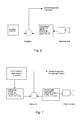
- FIG. 10 An example of the TCP / IP stream when sending status data from the operating software QT to the control center software LS shows Figure 9.
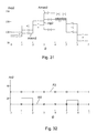
- An example of the TCP / IP stream when setting the ink keys shows the Fig. 10. This communication path is running within the printing machine, and from the inline inspection system via the control console software LS, the ARCNet, the PLC to the ink keys.
- Fig. 11 shows an example of the TCP / IP stream at Sending order data from the control room software LS to the operating software QT.
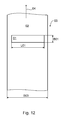
- a material 03 shown in Fig. 12 with a Surface 02 moves in a direction indicated by an arrow movement direction 04.
- the movement is done by a, z. B. arranged in or on the printing press, here not shown transport device, wherein the movement of the material 03 during the operation of the optical inline inspection system described in more detail below preferably takes place in only one direction of movement 04, and preferably linear.
- the material 03 is preferably planar and flat, z. B. as a sheet 03 or as a material web 03, is formed.
- the material 03 is especially as a z. B. made of paper existing substrate 03, z.
- the surface 02 of the material 03 may be a relief or other protruding from the surface 02 or into the Surface 02 as a depression embossed structure, wherein a height or Depth of the relief or the structure compared to a width B03 of the material 03 very is small. At least part of the surface 02 of the material 03 is z. B. by application a reflective material, e.g. As a paint, or a film by introducing a Window thread or other preferably metallic application in the material 03, reflective trained.
- a reflective material e.g. As a paint, or a film by introducing a Window thread or other preferably metallic application in the material 03, reflective trained.
- An illumination device 06 shown only symbolically in FIG. 13 generates the surface 02 of the material 03 an illuminated structure 01 in the form of a Illuminating strip 01 having a length L01 and a width B01 (Fig. 12), wherein the width B01 extends on the surface 02 of the material 03 orthogonal to the length L01.
- the width B01 of the illumination strip 01 is preferably along the Movement direction 04 of the material 03 directed, whereas the length L01 of the Illuminating strip 01 preferably parallel to the width B03 of the material 03, d. H. transverse to the direction of movement 04 of the material 03, is directed and spread over parts of Width B03 of the material 03 or over the entire width B03 can extend.
- the Width B01 of the illumination strip 01 is preferably at least 3 mm, in particular 8 mm.
- the direction of movement 04 of the material 03 is thus preferred at least substantially parallel to the width B01 of the illumination strip 01 directed, wherein the direction of movement 04 of the material 03 within the length of L01 and the width B01 of the illumination strip 01 plane spanned lies.
- the Material 03 is preferably not at least in the region of the illumination strip 01 arched.
- the illumination device 06 has a plurality of line-shaped juxtaposed Light sources 07, so that the entire lighting device 06 line-shaped is trained.
- the line-shaped light sources 07 of the Lighting device 06 are preferably parallel to the length L01 of Illuminating strip 01 arranged.
- the light sources 07 have the surface 02 of the Material 03 each have a distance A07, wherein the distance A07 preferably between 30 mm and 200 mm, in particular between 80 mm and 140 mm.
- the distance A07 of the light sources 07 is preferably perpendicular to the surface 02 of the Material 03. All light sources 07 of the illumination device 06 are preferably similarly formed, z. B. as bright, strong light emitting diodes 07 or as laser diodes 07.
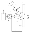
- a central plane of the juxtaposed light sources 07 of the Lighting device 06 emitted light and a central plane of the Lighting strips 01 to the camera 08 of reflected light preferably close one acute angle ⁇ with each other, the z. In the range between 15 ° and 60 °, in particular between 20 ° and 30 ° ( Figure 3).
- the lighting device 06 can also groups of several be provided in a row next to each other arranged light sources 07, wherein the individual groups of light sources 07 in their optical properties, eg. B. in the Distinguish the wavelength of the light emitted by them. So z. B. a group of light sources 07 emit white light, whereas another group of Light sources 07 monochrome light emitted. It can be provided that one with the Lighting device 06 connected control device 23, the groups of Light sources 07 depending on the application, z. B. depending on the nature of Surface 02 of the material 03 according to the color of the light, selected and individually controls. Thus, the controller 23 may also have a group of light sources 07 regardless of at least one other group of light sources 07 in their brightness and / or lighting duration.
- the illumination strip 01 is outside of an im direct or lying in the deflected beam path focal point of the Light sources 07 emitted light arranged.
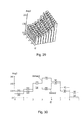
- the lighting device 06 is z. B. of several lines together tiered modules M61 to M65 (Fig. 23) each preferably with a plurality of line-shaped juxtaposed light sources 07, wherein a parting line 26 between two adjacent modules M61 to M65 preferably obliquely to the length L01 of Illuminating strip 01 is arranged.
- the individual modules M61 to M65 of Lighting device 06 may, for. B. be functionally identical. So z. B.
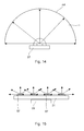
- FIG. 14 shows in a merely two-dimensional representation a single light source 07 of FIG Lighting device 06.
- the light source 07 emits its light in a solid angle ⁇ , where the solid angle ⁇ is an area AK cut out of a sphere, ie a Sphere surface AK, spans up to the size of a hemisphere.
- Fig. 15 shows several, z. B. four of the light sources 07 shown in FIG. 14 line-shaped arranged side by side on a common board 21. Preferably, it is too the respective light sources 07 belonging power source 22 on the same board 21st arranged.
- the current source 22 is preferably as a constant current source 22, in particular as a controllable constant current source 22, is formed.
- the in-line optical inspection system also includes - as can be seen in FIG. 13 a detection device 08 with at least one at a distance A09 from the Surface 02 of the material 03 arranged detector 09, wherein the detector 09 of the Surface 02 of the material 03 detected remitted light.
- the distance A09 is in Range between 10 mm and 1,500 mm, preferably between 50 mm and 400 mm.
- the detection device 08 is z. B. as a camera 08, preferably a Line camera 08, in particular a color line camera 08, formed.
- the Detection device 08 may be arranged in a row several juxtaposed Have detectors 09, wherein the line-shaped detectors 09 are preferably arranged parallel to the length L01 of the illumination strip 01.
- the Detector 09 of the detection device 08 may, for. As a CCD array 09 or as a Group of photodiodes 09 may be formed.
- the detector 09 of the detection device 08 converts the detected remitted light into an electrical signal and performs that electrical signal for its evaluation one with the detection device 08th connected image processing device 24 to.
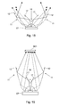
- FIG. 16 shows that in the optical inspection system, the light sources 07 of FIG Lighting device 06 at least a first mirror 11 with at least one longitudinally directed to the length L01 and / or to the width B01 of the illumination strip 01 Active surface 12 is assigned, wherein the active surface 12 of the first mirror 11 in the Solid angle ⁇ emitted light from at least one of the light sources 07 of the Lighting device 06 on a smaller first envelope surface AH1 than that to the Solid angle ⁇ belonging spherical surface AK restricts.
- the active surface 12 of the first Mirror 11 may be flat or concave.
- at least one light source 07 of the illumination device 06 a first mirror eleventh with at least two to one of the light source 07 emitted central beam 13th symmetrical active surfaces 12 on.
- a second Mirror 16 may be provided, wherein the at least one active surface 17 in which the Beam path of the central beam 13 surrounding the central region 14 within the Solid angle ⁇ of the light emitted from the light source 07 is arranged, the Working surface 17 of the second mirror 16 of at least one of the light sources 07 of the Lighting device 06 emitted light against at least one longitudinal to the length L01 and / or to the width B01 of the illumination strip 01 directed active surface 12 of the first Mirror 11 deflects.
- the radiation emitted by the light source 07 radiation preferably bundled more along the length L01 of the illumination strip 01 be considered the radiation along its width B01.
- the active surface 17 of the second Mirror 16 may be flat or concave.
- the central area 14 is to be assigned, emitted by the respective light sources 07 radiation is shown in FIGS to 21 each indicated with continuous arrow lines, whereas from the light sources 07 in their respective solid angle ⁇ peripherally emitted radiation with dashed Arrow lines is indicated.
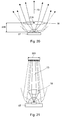
- the deflection of at least one of the light sources 07 the illumination device 06 in a central beam surrounding the central 13 Region 14 emitted radiation at least one lens 18, in particular a biconvex lens 18, in which the beam path of the central beam thirteenth surrounding central region 14 within the solid angle ⁇ of at least arranged one of the light sources 07 of the illumination device 06 emitted light be between the light source 07 and a center Z18 of the lens 18 a distance A18, wherein the distance A18 is preferably less than half the distance A07 is between the light source 07 and the surface 02 of the material 03.
- the lens 18 may not be rotationally symmetrical to the light from the 07th emitted radiation preferably along the length L01 of the illumination strip 01 to bundle more strongly than along its width B01.
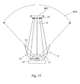
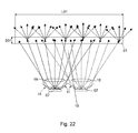
- FIG. 22 shows that the light sources 07 of the illumination device 06 are preferably are arranged such that the respective solid angle ⁇ or at least the Enveloping surfaces AH1; AH2 of at least two adjacent light sources 07 of Lighting device 06 emitted light at least in one Overlay lighting strip 01 illuminating portion 19.
- This overlay is in particular also provided when the participating adjacent light sources 07 are arranged in two adjacent modules M61 to M65.
- Fig. 22 is also it can be seen that at each individual light source 07 of the illumination device 06 respectively a first mirror 11 with at least one active surface 12, preferably with two mutually symmetrical active surfaces 12, at least along the width B01 of the Illuminating strip 01 may be provided.
- the surface 02 of the material 03 a scattering body, d. H.
- a light-scattering body z. B. a lenticular or a prism sheet, wherein the scattering body in the illumination strip 01 on the surface 02 of the material 03 radiated light preferably only or at least predominantly along the length L01 of the illumination strip 01 remitted.
- a further scattering body to another Homogenization of the emitted light from the illumination device 06 at the light Be arranged light exit side of the illumination device 06 and thus in the Light path between the light sources 07 of the illumination device 06 and to illuminating surface 02 of the material 03 are located.
- Such a light sources 07 upstream diffuser improves illumination of the surface 02 of the Material 03 in the sense of a shadow-free illumination when the surface 02 of the material 03 has an at least slight relief.
- Fig. 23 is a view of the optical inspection system in a direction perpendicular to Direction of movement 04 of the material 03 standing plane.
- the lighting device 06 and illuminated on the surface 02 of the material 03 lighting strip 01st are arranged at a distance A07 parallel to each other, but an extension of the Lighting device 06, d. H. their length B06, be greater than the length L01 of the Illuminating strip 01 or as the width B03 of the material 03.
- the Lighting device 06 is divided into preferably a plurality of modules M61 to M65, d. H. in this example, in five line-by-side modules M61 to M65, wherein the light sources 07 arranged in each module M61 to M65 each have light emit to the illumination strip 01.
- the remitted from the lighting strip 01 Light is disposed from the surface 02 of the material 03 at the distance A09 Detector 09 of the detection device 08 within a longitudinal to the length L01 of Illuminating strip 01 opening spatial detection angle ⁇ detected, the Acquisition angle ⁇ in this example is such that it is the from Lighting strip 01 remitted light over the entire length L01 of Illuminating strip 01 detected.
- the detection angle ⁇ forms on the surface 02 of the Material 03 from a cross-sectional area, so that the detection angle ⁇ at least a part of extending across the width B01 of the illumination strip 01 Cross-sectional area of the emitted from the illumination device 06 Detected light beam.
- the cross-sectional area detected by the detection angle ⁇ is preferably at least as large as that on the surface 02 of the material 03 through the Length L01 and width B01 of the illumination strip 01 spanned surface.
- the quality of one with the detection device 08 by detection of the Lighting strip 01 remitted light recorded image is relevant depending on that the light sources 07 of the illumination device 06 light emit constant light intensity. Because fluctuations in the light intensity of the Light sources 07 emitted light lead in the detection device 08 with respect to the the image processing device 24 supplied signal to the same result as Changes in the nature of the surface 02 of the illuminated material 03, so that in the image processing device 24, the causes of a signal change not can be distinguished. Under these circumstances, one can be found in the Image processing device 24 image evaluation made no reliable Statements about the nature of the surface 02 of the illuminated material 03 win.
- the in the Lighting device 06 used light sources 07 are preferably as bright light emitting diodes 07 or laser diodes 07 formed whose light intensity is temperature dependent. The following are to achieve a constant light intensity Measures for temperature stabilization arranged on the carrier 21 Light sources 07 described.
- the advantage of this solution is that the thermal Load of light sources 07 is dissipated directly at the point of origin, resulting in short Runtime can be achieved.
- the light sources 07 are preferably on one with another electronic Components can be fitted and provided with tracks printed circuit board 21.
- the semiconductor of the LEDs 07 or laser diodes 07 is preferably in direct Touch contact with the board 21, the z. B. as MCPCB (metal core printed circuit board) or as a circuit board 21 is formed with a core of aluminum and at its the light-emitting diodes 07 or laser diodes 07 bearing mounting side 32 for training the lowest possible heat transfer resistance only a very thin edition has its heat-conducting surface.
- Fig. 24 shows a circuit board 21 with a plurality of light sources arranged in a row 07, wherein the board 21 in turn on a support 27 made of a thermally conductive Material is arranged, wherein the carrier 27 preferably in its interior preferably below the line-shaped arrangement of the light sources 07, d. H. in as good as possible heat coupling to the light sources 07, at least one channel 28th having a liquid or gaseous cooling medium, for. As water or air, the Channel 28 flows through.
- Preferably frontally on the carrier 27 are for feeding and Leakage of the cooling medium connected to a flow opening 29 and a with a return connected opening 31 is provided, wherein the cooling medium the carrier 27 z. B. flows through in a straight line (Fig. 4).
- Fig. 4 Fig.
- the Cooling medium flows through in two opposite directions, whereby in the Carrier 27 a balanced along the line-shaped arrangement of the light sources 07 Temperature profile is achieved.
- the channel 28 at one end of the carrier 27th be deflected by 180 °.
- a control device not shown, the temperature of the cooling medium on Keep the flow and the flow through the channel 28 constant flow.
- the controller may also measure a difference between the temperature of the Coolant at the flow and the temperature of the coolant at the return constant hold. It is less the absolute temperature of the cooling medium of importance but rather, that a maximum temperature for the light sources 07, the does not result from the heat transfer resistances of the materials involved what is exceeded by the regulatory body by monitoring the Temperature of the cooling medium and a responsive control intervention is prevented. If a variable in its temperature or flow rate Cooling medium for cooling the light sources 07 is not sufficient, the cooling of the Light sources 07 by an external, not connected to the board 21 cooling device (not shown).
- cooling medium for. B. the cooling medium, the at least one in a Chill roller stand arranged cooling roller and / or at least one in an inking unit arranged color tempering and / or at least one in a dampening unit arranged dampening roller flows through.
- a plurality of cooling rollers havingdewalzenschreibr one in commercial printing working web-fed printing press in web running direction behind one of the printing unit downstream dryer, in particular a hot air or infrared dryer, arranged, which in their passage through the dryer z. B. heated to 130 ° C. Material web by their contact with the lateral surface of the cooling rollers preferably on Room temperature is cooled.
- the cooling medium should be a good one Have heat capacity. It is advantageous to one for cooling a cooling roll and / or a color tempering roller and / or a dampening roller and / or a Printing cylinder, z. B. cylinder form existing Kreisschul the used for it Cooling medium to expand and at the same time for cooling the light sources 07 of the Lighting device 06 to use. Also, it is advantageous if at the Lighting device 06 formed opening 29 for supplying the cooling medium and formed on the illumination device 06 opening 31 for discharging the Coolant each provided on the same front side of the illumination device 06 are because thereby the required for the transport of the coolant line laying, especially within the printing press, is simplified.
- the cooling medium preferably flows through the illumination device 06 completely, but at least within the modules M61 to M65 with at least one activated light source 07. With the Flow through the lighting device 06 with a liquid cooling medium leaves For the arranged in the lighting device 06 light sources 07 a Temperature stability of z. B. ⁇ 1 ° C, especially if the cooling medium of a corresponding control device is monitored.
- FIG. 26 An addition to cooling with a flowing cooling medium or an alternative to The use of a flowing cooling medium is shown in FIG. 26.
- the one with the light sources 07 populated board 21 is mounted on a support 27 made of a thermally conductive material arranged, wherein the carrier 27 in turn on at least one Peltier element 33, but preferably a plurality of Peltier elements 33, is arranged, wherein the Peltier elements 33 preferably each with a thermally separated from the carrier 27 Heat sink 34 are connected.
- a necessary temperature measurement to control the at least one Peltier element 33 by an electronic, not shown Control device is preferably directly on the carrier 27 by a at this attached temperature sensor 36 made. In fluctuating Ambient temperature then varies only the temperature of the heat sink 34, but not the temperature of the arranged on the board 21 light sources 07.
- the electronic Control device can in the connected to the illumination device 06 Control device 23 may be integrated.
- the optical inspection system is such to interpret that of the moving material 03 a useful image recording possible is. It should be noted that in a trained as a line camera 08 Detection device 08, the detected amount of the surface 02 of the moving Materials 03 remitted light depending on the speed of moving Material 03 changes. This also changes the brightness of the image recording. at greater speed changes, as in the mentioned machines Usually occur, the image acquisition can become unusable.
- a duty cycle t3 a single light source 07 or a group of light sources 07 of Lighting device 06, which is controlled by one of the control device 23 Current source 22, in particular a constant current source 22, are driven, with a trigger, d. H. an exposure time t1 of the line scan camera 08 to synchronize, so that the surface 02 of the moving material 03 is independent of the Speed of the moving material 03 always with the same amount of light is illuminated. This results in a constant brightness for that of the Line scan 08 captured image over a wide range of speed of the moving material 03.
- a plurality of groups of light sources 07 are provided, each having at least one Current source 22, in particular a constant current source 22, is assigned.
- the Switch-on times t3 of the light sources 07 are determined by the illumination device 06 Connected control device 23 z. B. groupwise or individually individually controlled by the respective current sources 22, so over the length the preferably line-shaped light sources 07 of the illumination device 06 lets you set a light quantity profile.
- the setting of a light quantity profile preferably along the length L01 of the illumination strip 01 has the advantage that Transmission losses through a not shown optics of the line scan 08 can be compensated.
- a z. B. with the controller 23rd connected light sensor 37, the emitted light amount of the light sources 07 of Illumination device 06 measures in order to use the measurement signal of the light sensor 37, the Duty cycle t3 of the current sources 22 with the control device 23 controlled Light sources 07 z. B. adapt to a Degradations the light sources 07 and with the control of the light sources 07 z. B. one with their aging decreasing Compensating radiation in their amount of light. Also, the controller 23 may the duty cycle t3 of the light sources 07 to different optical properties of the Automatically adjust material 03 to be illuminated.
- Fig. 27 shows the timing of the line scan camera 08 and that of the light sources 07.
- the Line scan camera 08 becomes a particular one according to the upper, first time history Time switched on, so that at this time, the exposure time t1 the Line scan camera 08 begins. After expiration of the exposure time t1 immediately follows one of the speed of the moving material 03 dependent timeout t2 between two successive, adjacent image lines of the line scan 08.
- At least one in Dependence on the control of the line camera 08 triggered light source 07 is in accordance with the mean, second time course in FIG. 27 from that of the control device 23 controlled current source 22 simultaneously with the exposure time t1 of the line scan camera 08 driven, wherein after a delay time t4 for the activation of the light source 07, d. H.
- this Light source 07 then remains switched on for the duty cycle t3, where a sum consisting of the delay time t4 and the duty cycle t3 preferably lower is measured as the exposure time t1 of the line camera 08th Die Zeit für die Line scan camera 08 and the light sources 07 repeats periodically in the previous described fixed correlation. Only as a comparison to that in their duty cycle t3 Triggered light source 07 is in the lower, third time course of FIG. 27 Time response of the duty cycle t5 for a constant light source shown.
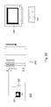
- the suitable for the print image control Inspection system according to its schematic representation in FIG. 28 an or a plurality of color line cameras 201 coupled to one another or a color area camera 201 having a printed image 203 illuminated by a lighting device 202 receives, with the print image 203 with the printing press on a z. B. made of paper existing printing material has been generated.
- From the color line camera 201 or the Color area camera 201 amplitude values determined from the recording of the print image Axy2 of the individual color channels are billed in an image processing system 204.
- the output of the result is z. B. on one with the image processing system 204 connected monitor 206.
- inputs, z. B. the image processing system 204 for his calculations necessarily to be communicated parameters are over one input the image processing system 204 connected keyboard 207.
- Fig. 29 shows a two-dimensional representation of a resulting from the recording of the printed image, For example, square pixel field, the pixel field in its base z. B. consists of 8x8 pixels and the amplitude values Axy2 of the pixel field on the High axis are applied.
- Data taken or derived from the pixel field only for a one-dimensional Range from a single line to z.
- FIG. 30 shows a preferably generated from several shots reference image with the respective maximum values Aimax2 and minimum values Aimin2 for each pixel i2. Subsequently, the amplitude values Aip2 of the currently recorded print image with this from the course of the respective maximum values Aimax2 and minimum values Aimin2 compared existing reference image and determined the deviations, as the Fig. 31 shows.
- the contrast AK2 becomes the reference image for each deviation rated.
- the evaluation is made via two separately to be set Decision thresholds W2 and F2, where a decision threshold is a Warning threshold W2 and the other decision threshold an error threshold F2 form (Fig. 32).
- a decision threshold is a Warning threshold W2 and the other decision threshold an error threshold F2 form (Fig. 32).
- the display of the deviations takes place on the monitor 206 z. B. separated according to the type of Deviation preferably in different colors, the display on the Monitor 206 preferably superimposed exact position on the current print image is blended. The operator is thus enabled, while the production is running Immediately recognize in which printing unit the cause of a printing press Deviation in the quality of the printed product occurs. The cause can then be evaluated and corrected.
Abstract
Description
Die Erfindung betrifft Druckmaschinen mit einem Inline-Inspektionssystem gemäß dem
Oberbegriff des Anspruchs 1, 4 oder 9.The invention relates to printing presses with an in-line inspection system according to the
The preamble of
Die Anwendung besteht vorrangig in der Beurteilung einer Qualität einer von einer Druckmaschine produzierten Drucksache, wobei die Druckmaschine vorzugsweise als eine Rotationsdruckmaschine, insbesondere als eine in einem Offsetdruckverfahren, in einem Stahlstichverfahren, in einem Siebdruckverfahren oder in einem Heißprägeverfahren druckende Druckmaschine ausgebildet ist.The application consists primarily in the evaluation of a quality one of a Printing machine produced printed matter, the printing machine preferably as a rotary printing machine, in particular as one in an offset printing method, in a steel engraving process, in a screen printing process or in a Hot embossing process printing press is formed.
Durch die DE 41 02 122 A1 ist ein zur Anwendung in der Druckindustrie geeignetes Verfahren zur Untersuchung von bahnförmigem, durchscheinendem Material, insbesondere einer Papierbahn, bekannt, bei dem z. B. mit Leuchtdioden oder Laserdioden verwirklichte Blitzlichtlampen durch eine Papierbahn strahlen, bei dem durch die Papierbahn strahlendes Licht zur Erzeugung eines Videosignals auf eine CCD-Matrix einer Kamera fällt.DE 41 02 122 A1 is suitable for use in the printing industry Method for the examination of sheet-like, translucent material, in particular a paper web, known in the z. B. with LEDs or Laser diodes realized flash lamps shine through a paper web, in which the paper web radiating light for generating a video signal on a CCD matrix a camera falls.
Durch die DE 43 21 177 A1 ist eine Druckmaschine mit einer Inline-Bildinspektionseinrichtung zur Inspektion eines in der Druckmaschine erstellten Druckproduktes bekannt, wobei eine Bilddaten vom Druckprodukt an eine Recheneinrichtung liefernde Bilderfassungseinrichtung vorgesehen ist, wobei die Bilderfassungseinrichtung aus einem Messmodul oder mehreren jeweils einen definierten Bildbereich des Druckproduktes abtastenden Messmodulen und aus zumindest einer zugeordneten, die Bilddaten in elektrischer Form bereitstellenden und vorzugsweise von den Messmodulen räumlich getrennten Empfangseinrichtung besteht, wobei die Messmodule und die mindestens eine Empfangseinrichtung mittels mindestens eines Bildleiters miteinander verbunden sind, wobei der Bilderfassungseinrichtung eine aus Präzisionshalogenlampen bestehende Beleuchtungseinrichtung zugeordnet ist, wobei ein Blasluftrohr mit Öffnungen in Richtung des Druckproduktes bei seiner Blasluftbeaufschlagung das Druckprodukt in einem definierten Abstand zur Beleuchtungseinrichtung hält und gleichzeitig mit der Blasluft die Beleuchtungseinrichtung kühlt.From DE 43 21 177 A1 is a printing machine with an inline image inspection device for inspection of a machine created in the printing press Print product known, wherein an image data from the printed product to a Computing device providing image capture device is provided, wherein the Image capture device from one measurement module or several each one defined Image area of the printed product scanning measuring modules and at least one associated, the image data in electrical form providing and preferably of the measuring modules spatially separated receiving device, wherein the Measuring modules and the at least one receiving device by means of at least one Image guide are connected to each other, wherein the image capture device from a Precision halogen lamps is associated with existing lighting device, wherein a Blasluftrohr with openings in the direction of the printed product at his Blasluftbeaufschlagung the printed product at a defined distance from Lighting device holds and at the same time with the blowing air, the lighting device cools.
Durch die DE 100 61 070 A1 ist eine Beleuchtungseinrichtung für eine optische
Inspektionseinrichtung zur Untersuchung von Oberflächen bekannt, wobei mehrere
vorzugsweise gleich lange, elektrisch miteinander verschaltete Trägerplatinen mit jeweils
mehreren Reihen von Leuchtdioden linienartig in einem gemeinsamen, entsprechend der
mit einer konstanten Lichtabstrahlung abzutastenden Objektfläche längbaren, steifen
Montageprofil eingeschoben sind, wobei zwischen den Trägerplatinen und dem
Montageprofil über eine mechanische Verbindung eine Wärmekopplung zur Kühlung der
Leuchtdioden und ihrer Ansteuerelektronik erfolgt. Ein Hinweis auf einen Einsatz dieser
Beleuchtungseinrichtung in einer Druckmaschine während einer Inspektion eines durch
die Druckmaschine transportierten Bedruckstoffes ist nicht gegeben.From
Durch die DE 202 13 431 U1 ist eine Einrichtung zur Qualitätskontrolle an Drucksachen bekannt, die gleichfalls ein in einer Druckmaschine angeordnetes Inline-Bildinspektionssystem bildet, wobei eine als eine Leuchtstoffröhre ausgebildete Beleuchtungseinrichtung und eine als eine Zeilenkamera ausgebildete Bildaufnahmeeinrichtung zum Einsatz gebracht werden. Maßnahmen für eine konstante Lichtabstrahlung sind nicht beschrieben.By DE 202 13 431 U1 is a device for quality control of printed matter which is also an in-line image inspection system arranged in a printing press forms, with one designed as a fluorescent tube Lighting device and designed as a line scan camera Image recording device are used. Measures for a constant Light emission are not described.
Durch die DE 203 03 574 U1 ist ein Inline-Bildinspektionssystem für eine Druckmaschine, insbesondere einer Bogenoffsetdruckmaschine, bekannt, wobei eine als eine Leuchtstofflampe ausgebildete Beleuchtungseinrichtung unterhalb eines Fußtrittes nahe an einem einen Bedruckstoff führenden Gegendruckzylinder und eine als eine Zeilenkamera ausgebildete Bildaufnahmeeinrichtung in einem im Vergleich zur Beleuchtungseinrichtung weiteren Abstand vom Gegendruckzylinder in einer Zuordnung zum letzten Druckwerk der Druckmaschine angeordnet ist. Es findet sich jedoch kein Hinweis auf Maßnahmen für eine konstante Lichtabstrahlung durch die Beleuchtungseinrichtung.By DE 203 03 574 U1 is an inline image inspection system for a printing press, in particular a sheet-fed offset printing machine, one known as one Fluorescent lamp formed lighting device below a kick close on a printing material leading impression cylinder and one as a Line scan camera formed image recording device in a compared to Lighting device further distance from the impression cylinder in an assignment is arranged to the last printing unit of the printing press. However, there is no Reference to measures for a constant light emission through the Lighting device.
Durch die EP 0 762 174 A2 ist eine Vorrichtung zur linienförmigen Beleuchtung von
Blattgut, wie z. B. Banknoten oder Wertpapieren, bekannt, wobei ein zylindrischer Spiegel
mit zwei Spiegelsegmenten vorgesehen ist, wobei die Spiegelsegmente eine elliptische,
zwei Fokuslinien aufweisende Grundfläche ausbilden, wobei die Breite der
Spiegelsegmente größer oder gleich der Breite des Blattguts gewählt ist, wobei in der
ersten Fokuslinie das von einer Transportvorrichtung senkrecht zu dieser Fokuslinie
transportierte Blattgut und in der zweiten Fokuslinie eine Kaltlichtquelle, z. B. eine Reihe
von Leuchtdioden (LED's), angeordnet ist, wobei ein Detektor, z. B. ein CCD-Array oder
einzeln oder in Gruppen angeordnete Photodioden, das vom Blattgut remittierte Licht
erfasst und in Signale zur Bearbeitung in einer Bearbeitungsanlage umwandelt.
Durch die US 4,972,093 ist ein Inspektionssystem bekannt, wobei ein bewegter Prüfling von einer impulsartig angesteuerten Leuchtdiodenanordnung mit einem zwischen 20 ms und 200 ms dauernden Lichtblitz beaufschlagt wird und eine Flächenkamera ein Bild von dem gesamten Prüfling aufnimmt.By the US 4,972,093 an inspection system is known, wherein a moving DUT from a pulsed light emitting diode arrangement with a between 20 ms and 200 ms continuous flash of light is applied and a surface camera an image of takes up the entire examinee.
Durch die US 5,936,353 ist ein optisches System zur Erzeugung eines beleuchteten Gebildes auf einer Oberfläche eines relativ zum Gebilde bewegten Materials bekannt, wobei eine Beleuchtungseinrichtung mit mehreren Lichtquellen Licht zur Erzeugung des Gebildes emittiert, wobei eine Erfassungseinrichtung mit mindestens einem Detektor von der Oberfläche des Materials remittiertes Licht erfasst, wobei die Lichtquellen auf einer Platine angeordnet sind, wobei die Platine auf einem Träger angeordnet ist, wobei der Träger in seinem Inneren mindestens einen Kanal aufweist, wobei ein flüssiges oder gasförmiges Kühlmedium zur Kühlung der Lichtquellen den Kanal durchströmt. Maßnahmen zur Erzielung einer konstanten Lichtstärke der auf dem Träger angeordneten Lichtquellen sind nicht beschrieben.By US 5,936,353 is an optical system for generating a lit. Formed on a surface of a material moving relative to the structure, wherein a lighting device with a plurality of light sources generates light for generating the Formed emitted, wherein a detection device with at least one detector of the light reflected on the surface of the material, the light sources on a Board are arranged, wherein the circuit board is arranged on a support, wherein the Carrier has in its interior at least one channel, wherein a liquid or gaseous cooling medium for cooling the light sources flows through the channel. Measures to achieve a constant light intensity arranged on the support Light sources are not described.
Der Erfindung liegt die Aufgabe zugrunde, Druckmaschinen mit einem Inline-Inspektionssystem zu schaffen.The invention is based on the object printing presses with an inline inspection system to accomplish.
Die Aufgabe wird erfindungsgemäß durch die Merkmale des Anspruchs 1, 4 oder 9 gelöst.The object is achieved by the features of
Die mit der Erfindung erzielbaren Vorteile bestehen insbesondere darin, dass die Druckmaschine ein Inline-Inspektionssystem mit einer Beleuchtungseinrichtung aufweist, wobei die Lichtquelle der Beleuchtungseinrichtung ihr Licht trotz Eigenerwärmung oder externer Wärmeeinflüsse zufolge einer Kühlung ihrer Lichtquelle mit einer hohen Konstanz abstrahlt. Eine konstante Lichtabstrahlung ist erforderlich, um eine in ihrem Druckprozess inspizierte Drucksache hinsichtlich ihrer Qualität verlässlich beurteilen zu können, denn eine Veränderung oder Schwankung in der Lichtabstrahlung kann zu einer Fehlinterpretation der von der Drucksache aufgenommenen Bilddaten und damit zu einem nicht sachgerechten Eingriff in den Druckprozess führen. Die vorgeschlagene Lösung hat den Vorteil, dass die thermische Last der Lichtquelle direkt am Entstehungsort abgeführt wird, wodurch sich kurze Regelzeiten zur Einhaltung einer konstanten Lichtabstrahlung erreichen lassen. Auch lässt sich mit den vorgeschlagenen Maßnahmen eine hohe Lichtausbeute erreichen.The achievable with the present invention consist in particular that the Printing machine has an inline inspection system with a lighting device, wherein the light source of the illumination device, despite its own warming or light external heat influences due to a cooling of their light source with a high Constance radiates. A constant light emission is required to make one in her Print process inspected to reliably assess their quality can, because a change or fluctuation in the light emission can lead to a Misinterpretation of the image data taken from the printed matter and thus to a improper intervention in the printing process. The proposed solution has the advantage that the thermal load of the light source dissipated directly at the point of origin , resulting in short control times to maintain a constant light emission achieve. Also can be with the proposed measures a high Reach light output.
Überdies bestehen Vorteile darin, dass das Material, auf dessen Oberfläche ein beleuchtetes Gebilde zu erzeugen ist, nicht in einem im direkten oder im umgelenkten Strahlengang liegenden Brennpunkt des von den Lichtquellen emittierten Lichtes angeordnet sein muss, um das Gebilde in einer ausreichenden Beleuchtungsstärke erscheinen zu lassen. Eine vom Brennpunkt unabhängige Anordnung des Gebildes relativ zu seinem optischen System ist vorteilhaft, weil dann auf eine exakte Maßhaltigkeit bezüglich des Abstandes zwischen dem Gebilde und der Beleuchtungseinrichtung verzichtet werden kann. Das beschriebene optische System ist demnach zum beleuchteten Material abstandstolerant. Außerdem ist zwischen Bauelementen des optischen Systems, die durch eine Verschmutzung, z. B. durch Staub und Abrieb, in ihrer Funktion beeinträchtigt werden können, und dem Material, insbesondere auch zu einer das Material bewegenden Transporteinrichtung, ein ausreichender Abstand vorgesehen, der das optische System und das Material unter den gegebenen Betriebsbedingungen in einer Druckmaschine dauerhaft und zuverlässig außerhalb eines Berührungskontaktes belässt und das optische System vorzugsweise außerhalb der Reichweite der vom bewegten Material aufgewirbelten Schmutzpartikel anordnet.Moreover, there are advantages in having the material on the surface thereof illuminated entity is to generate, not in a direct or in the deflected Beam path lying focal point of the light emitted by the light sources must be arranged to the structure in a sufficient illuminance to appear. An independent of the focus arrangement of the structure relative to his optical system is advantageous, because then to an exact dimensional accuracy with respect to the distance between the structure and the illumination device can be waived. The described optical system is therefore for illuminated material distance tolerant. It is also between components of the optical system caused by contamination, eg. B. by dust and abrasion, in their Function can be impaired, and the material, in particular to a the material moving transport device, provided a sufficient distance, the optical system and the material under the given operating conditions in a printing press permanently and reliably outside a touch contact leaves and the optical system preferably out of range of the Moving material arranged swirled dirt particles.
Ein von der Beleuchtungseinrichtung beleuchteter Beleuchtungsstreifen mit einer sich auf der Oberfläche des Materials orthogonal zu seiner Länge erstreckenden Breite, d. h. ein zweidimensionales, flächiges Gebilde, hat gegenüber einem auf einen Brennpunkt fokussierten linienförmigen, d. h. nur eindimensionalen, beleuchteten Gebilde den Vorteil, dass das beleuchtete Gebilde für eine zur Oberfläche des zumindest in Teilen reflektivem Materials unter einem Reflexionswinkel angeordnete Erfassungseinrichtung zur Erfassung des von der Oberfläche des Materials remittierten Lichtes auch bei einer reliefartigen Ausgestaltung der Oberfläche des Materials zuverlässig als eine virtuelle zeilenförmige Beleuchtungseinrichtung erscheint, weil aufgrund der Breite des Beleuchtungsstreifens sichergestellt ist, dass eine an der Oberfläche des Materials vorhandene Querschnittsfläche eines Erfassungswinkels der Erfassungseinrichtung, in welchem die Erfassungseinrichtung remittiertes Licht zu erfassen vermag, zumindest einen Teil einer sich über die Breite des Beleuchtungsstreifens erstreckenden Querschnittsfläche des von der Beleuchtungseinrichtung emittierten Lichtstrahlenbündels erfasst. Bei einer Vorrichtung, die Material nur linienförmig beleuchtet, besteht die Gefahr, dass das fokussierte Strahlenbündel von einer reliefartigen Oberfläche des Materials außerhalb des Erfassungswinkels der Erfassungseinrichtung reflektiert wird und folglich nicht erfasst werden kann. Im Gegensatz dazu ist das beschriebene optische System auch für eine Bildaufnahme von Material mit einer diffus reflektierenden Oberfläche gut geeignet. Selbst bei einem Material mit einer reliefartigen Oberfläche tritt kaum eine Schattenwirkung auf.A illuminated by the lighting device lighting strip with a on the surface of the material orthogonal to its length extending width, d. H. on two-dimensional, flat structure, has opposite to a focus focused linear, d. H. only one-dimensional, illuminated entities have the advantage that the illuminated structure for a reflective to the surface of the at least partially Material arranged under a reflection angle detecting means for detection of the light remitted from the surface of the material even in a relief-like Design of the surface of the material reliably as a virtual line-shaped Lighting device appears because due to the width of the lighting strip it is ensured that one is present on the surface of the material Cross sectional area of a detection angle of the detection device, in which the Detecting device to detect reflected light is able to at least part of a over the width of the illumination strip extending cross-sectional area of detected light beam emitted by the illumination device. At a Device that illuminates material only linearly, there is a risk that the focused beams of a relief-like surface of the material outside of the Detection angle of the detection device is reflected and therefore not detected can be. In contrast, the described optical system is also for a Image capture of material with a diffuse reflective surface well suited. Even in the case of a material with a relief-like surface, hardly any shadowing effect occurs.
Die Beleuchtungseinrichtung des Inline-Inspektionssystems ist vorzugsweise in Modulen, d. h. in eigenständigen Funktionseinheiten, aufgebaut, was den Vorteil hat, dass eine Zeilenlänge der zeilenförmigen Beleuchtungseinrichtung ohne teure Sonderanfertigung durch einfaches Aneinanderreihen von vorgefertigten, vorzugsweise funktionsgleichen Modulen in der benötigten Anzahl an die Breite des zu beleuchtenden Materials oder zumindest an die Länge des Beleuchtungsstreifens adaptierbar ist. Gleichfalls können auch wahlweise zielgerichtet die Lichtquellen nur in denjenigen Modulen aktiviert werden, die zur Beleuchtung der Breite des zu beleuchtenden Materials oder zumindest der Länge des Beleuchtungsstreifens benötigt werden, was beim Aufbau und beim Betrieb des optischen System für dessen Wirtschaftlichkeit von Vorteil ist.The lighting device of the in-line inspection system is preferably in modules, d. H. in separate functional units, built, which has the advantage that a Line length of the line-shaped lighting device without expensive custom-made by simply juxtaposing prefabricated, preferably functionally identical Modules in the required number to the width of the material to be illuminated or is adaptable at least to the length of the illumination strip. Likewise also selectively, the light sources are activated only in those modules, to illuminate the width of the material to be illuminated or at least the length of the lighting strip are needed, which in the construction and operation of the optical system for its economy is beneficial.
Die Verwendung von mehreren Lichtquellen je Modul hat den Vorteil, dass sich in der Praxis unvermeidbare Unterschiede in dem von den Lichtquellen abgestrahlten Licht, z. B. in dessen Wellenlänge, durch Mischung der Strahlenbündel von benachbarten Lichtquellen vergleichmässigen und das von der Beleuchtungseinrichtung insgesamt abgestrahlte Licht in seinen optischen Eigenschaften homogenisieren. Wenn in jedem Modul vorzugsweise mehrere Gruppen von Lichtquellen angeordnet sind, wobei sich die den Gruppen zugeordneten Lichtquellen in ihren optischen Eigenschaften unterscheiden, z. B. in der Farbe des von den Lichtquellen einer jeden Gruppe ausgestrahlten Lichtes, können die einzelnen Gruppen von Lichtquellen applikationsabhängig, z. B. nach der Farbe des Lichtes, ausgewählt und angesteuert werden.The use of multiple light sources per module has the advantage that in the Practice unavoidable differences in the light emitted by the light sources, e.g. B. in its wavelength, by mixing the beams of neighboring Light sources even and that of the lighting device in total homogenize radiated light in its optical properties. If in each Module preferably a plurality of groups of light sources are arranged, wherein the distinguish the light sources assigned to the groups in their optical properties, z. In the color of the light emitted by the light sources of each group, can the individual groups of light sources application-dependent, z. B. after Color of light to be selected and controlled.
Die Beleuchtungseinrichtung des Inline-Inspektionssystems hat den Vorteil, dass sie einen unter Umständen eine große Länge von z. B. über einen Meter aufweisenden Beleuchtungsstreifen durch eine gleichmäßige, bedarfsgerechte Lichtverteilung mit einer homogenen, ausreichend großen Beleuchtungsstärke beaufschlagt und durch seinen modularen, wenig störanfälligen Aufbau auf einfache Weise an die jeweiligen Erfordernisse in einer Druckmaschine anpassbar ist. Da das zu beleuchtende Material nicht in einem Brennpunkt der Beleuchtungseinrichtung anzuordnen ist, entfällt auch die Notwendigkeit für eine exakte Ausrichtung des senkrechten Abstandes der Lichtquellen zur Oberfläche des Materials sowie eine Überwachung dieses Abstandes während des laufenden Einsatzes des optischen Systems, was die Handhabung des optischen Systems Vorort in einem Industriebetrieb erheblich vereinfacht.The lighting device of the in-line inspection system has the advantage of being a possibly a long length of z. B. over one meter Lighting strips by a uniform, needs-based light distribution with a homogeneous, sufficiently large illuminance applied and by his modular, low failure prone structure in a simple way to the respective Requirements in a printing machine is customizable. Because the material to be illuminated is not to be placed in a focal point of the lighting device, also eliminates the Need for an exact alignment of the vertical distance of the light sources to the surface of the material as well as a monitoring of this distance during the ongoing use of the optical system, resulting in the handling of the optical Systems suburb in an industrial plant greatly simplified.
Ebenso ist es ein Vorteil, dass ein langsam aufbauender Fehler in einem laufenden Druckprozess frühzeitig erkannt und dessen Ursache vom Bedienpersonal durch eine manuell durchzuführende oder automatisierte Gegenmaßnahme behoben werden kann, bevor die Qualität des Druckerzeugnisses einen als schlecht klassifizierbaren Zustand annimmt und der Druckprozess zu einer Produktion fehlerbehafteter, nicht verkaufsfähiger Druckerzeugnisse führt. Die zusätzlich zu einer Entscheidung über eine gute oder schlechte Druckqualität vorgesehene weitere Entscheidungsschwelle ermöglicht, dass eine geringe, noch im Toleranzbereich liegende Abweichung von in der laufenden Produktion erzeugten Druckbildern angezeigt wird, bevor sich diese Abweichung zu einem kritischen Fehler aufbaut. Dadurch kann frühzeitig eine geeignete Gegenmaßnahme ergriffen werden, ohne das diese Abweichung zu einer Produktion von Druckerzeugnissen mit einer schlechten Qualität führt. Eine Beurteilung der Qualität des Druckerzeugnisses in definierten Qualitätsstufen setzt zur Vermeidung von Fehlinterpretationen voraus, dass die aufgenommenen Bilddaten verlässlich und aussagekräftig sind, was nur mit einer Beleuchtungseinrichtung mit einer Lichtquelle mit einer im Druckprozess konstanten Lichtabstrahlung gegeben ist.Likewise it is an advantage that a slowly building up mistake in a running Printing process detected early and the cause of the operator by a can be remedied manually or automated countermeasure, before the quality of the printed matter classified as a bad condition and the printing process leads to a production of defective, non-salable ones Print products leads. The addition to a decision on a good or poor print quality provided further decision threshold allows that a small, still within the tolerance range deviation from in the current Production generated print images is displayed before this deviation too building a critical error. This can be an appropriate early Countermeasure taken without this deviation to a production of Print products with a poor quality leads. An assessment of the quality of the Print product in defined quality levels sets to avoid Misinterpretations that the recorded image data is reliable and meaningful, which is only possible with a lighting device with a light source a constant in the printing process light emission is given.
Ausführungsbeispiele der Erfindung sind in den Zeichnungen dargestellt und werden im Folgenden näher beschrieben.Embodiments of the invention are illustrated in the drawings and are in Described in more detail below.
Es zeigen:
- Fig. 1
- ein Schema einer Fünffarbendruckmaschine mit einem Lackturm und einer Auslageverlängerung;
- Fig. 2
- ein Blockschaltbild zur Systemstruktur eines Systems zur Beurteilung einer Qualität einer von der Druckmaschine produzierten Drucksache;
- Fig. 3
- eine Anordnung des Inline-Inspektionssystems in der Druckmaschine;
- Fig. 4
- eine perspektivische Darstellung des Inline-Inspektionssystems in der Druckmaschine;
- Fig. 5
- eine weitere perspektivische Darstellung des Inline-Inspektionssystems in der Druckmaschine;
- Fig. 6
- ein Schema zur Farbdichteregelung mit einem Farbmessstreifen;
- Fig. 7
- ein Schema einer Farbbestimmung und Farbregelung anhand des Druckbildes;
- Fig. 8
- ein Diagramm zum Verstellvorgang an einer Zonenschraube mit einer Verstellung von Nachbarzonen;
- Fig. 9
- ein TCP/IP-Stream beim Senden von Statusdaten von einer Bediensoftware zu einer Leitstandsoftware;
- Fig. 10
- ein TCP/IP-Stream beim Setzen von Farbzonenschrauben;
- Fig. 11
- ein TCP/IP-Stream beim Senden von Auftragsdaten von der Leitstandsoftware zur Bediensoftware;
- Fig. 12
- eine Oberfläche eines bewegten Materials mit einem Beleuchtungsstreifen in einer Draufsicht;
- Fig. 13
- eine schematische Darstellung des Inline-Inspektionssystems;
- Fig. 14
- eine einzelne Lichtquelle der Beleuchtungseinrichtung;
- Fig. 15
- eine zeilenförmige Anordnung von Lichtquellen auf einer gemeinsamen Platine;
- Fig. 16
- eine Strahlenbündelung mit einem ersten Spiegel;
- Fig. 17
- eine Strahlenbündelung mit einem ersten Spiegel längs zur Länge des Beleuchtungsstreifens;
- Fig. 18
- eine Umlenkung des Strahlenbündels aus einem zentralen Bereich der Lichtquelle mit einem zweiten Spiegel;
- Fig. 19
- eine Umlenkung des Strahlenbündels aus einem zentralen Bereich der Lichtquelle mit einem zweiten Spiegel, wobei die Strahlung längs zur Länge des Beleuchtungsstreifens stärker gebündelt ist als längs zu dessen Breite;
- Fig. 20
- eine Bündelung der Strahlung aus einem zentralen Bereich der Lichtquelle mit einer Konvexlinse;
- Fig. 21
- eine Bündelung der Strahlung aus einem zentralen Bereich der Lichtquelle mit einer Konvexlinse, wobei die Strahlung längs zur Länge des Beleuchtungsstreifens stärker gebündelt ist als längs zu dessen Breite;
- Fig. 22
- eine zumindest teilweise Überlagerung der Strahlung von zwei benachbarten Lichtquellen;
- Fig. 23
- eine Seitenansicht des Inline-Inspektionssystems;
- Fig. 24
- eine mit Lichtquellen bestückte Platine auf einem von einem Kühlmedium durchströmten Träger;
- Fig. 25
- einen in zwei entgegengesetzten Richtungen von einem Kühlmedium durchströmten Träger;
- Fig. 26
- einen Träger mit einer Kühlung mit zwei Peltierelementen;
- Fig. 27
- eine Darstellung des Zeitverhaltens der Zeilenkamera und desjenigen der Lichtquellen;
- Fig. 28
- eine weitere schematische Darstellung von Funktionseinheiten des Inline-Inspektionssystems;
- Fig. 29
- eine zweidimensionale Darstellung eines Pixelfeldes;
- Fig. 30
- ein Referenzbild mit Minimal- und Maximalwerte für jedes Pixel;
- Fig. 31
- ein Vergleich des aktuell aufgenommenen Druckbildes mit seinem Referenzbild;
- Fig. 32
- eine Darstellung der Bewertung der Abweichung zum Referenzbild über zwei Entscheidungsschwellen.
- Fig. 1
- a schematic of a five-color printing machine with a coating tower and a delivery extension;
- Fig. 2
- a block diagram of the system structure of a system for assessing a quality of a printed matter produced by the printing press;
- Fig. 3
- an arrangement of the inline inspection system in the printing press;
- Fig. 4
- a perspective view of the in-line inspection system in the printing press;
- Fig. 5
- another perspective view of the in-line inspection system in the printing press;
- Fig. 6
- a scheme for color density control with a colorimeter;
- Fig. 7
- a scheme of color determination and color control based on the printed image;
- Fig. 8
- a diagram for the adjustment of a zone screw with an adjustment of neighboring zones;
- Fig. 9
- a TCP / IP stream when sending status data from an operating software to a control room software;
- Fig. 10
- a TCP / IP stream when setting ink fountain keys;
- Fig. 11
- a TCP / IP stream when sending job data from the control room software to the operating software;
- Fig. 12
- a surface of a moving material with a lighting strip in a plan view;
- Fig. 13
- a schematic representation of the inline inspection system;
- Fig. 14
- a single light source of the illumination device;
- Fig. 15
- a row-shaped arrangement of light sources on a common board;
- Fig. 16
- a radiation beam with a first mirror;
- Fig. 17
- beamforming with a first mirror along the length of the illumination strip;
- Fig. 18
- a deflection of the radiation beam from a central region of the light source with a second mirror;
- Fig. 19
- a deflection of the radiation beam from a central region of the light source with a second mirror, wherein the radiation is bundled more along the length of the illumination strip than along its width;
- Fig. 20
- a bundling of the radiation from a central region of the light source with a convex lens;
- Fig. 21
- bundling the radiation from a central region of the light source with a convex lens, wherein the radiation is focused more along the length of the illumination strip than along its width;
- Fig. 22
- an at least partial superposition of the radiation from two adjacent light sources;
- Fig. 23
- a side view of the inline inspection system;
- Fig. 24
- a board equipped with light sources on a carrier through which a cooling medium flows;
- Fig. 25
- a carrier through which a cooling medium flows in two opposite directions;
- Fig. 26
- a carrier with a cooling with two Peltier elements;
- Fig. 27
- a representation of the timing of the line scan camera and that of the light sources;
- Fig. 28
- a further schematic representation of functional units of the inline inspection system;
- Fig. 29
- a two-dimensional representation of a pixel field;
- Fig. 30
- a reference image with minimum and maximum values for each pixel;
- Fig. 31
- a comparison of the currently recorded print image with its reference image;
- Fig. 32
- a representation of the deviation from the reference image over two decision thresholds.
Nach dem heutigen Stand der Erkenntnis sind im Offsetdruck im Bereich der Inline-Begutachtung zwei wesentliche Aspekte der Qualitätssicherung zu berücksichtigen. Zum einen muss eine Farbkonstanz im Sinne einer Dichte- und Farbortbestimmung während der Produktion gewährleistet sein, zum anderen müssen typische Fehler, wie z. B. Butzen oder Tonen, detektiert werden können.According to the current state of knowledge in offset printing in the area of inline inspection to consider two essential aspects of quality assurance. To the one must have a color consistency in the sense of a density and color determination during be assured of production, on the other hand, typical errors, such. B. slugs or cloning, can be detected.
Aus den in der Praxis gesammelten Erfahrungen hängt eine "Gutproduktion" von einer großen Anzahl von Randbedingungen ab, die nicht allein von Qualitätsdefinitionen eines QS-Managements festgelegt werden können. Aufgrund der in der Praxis vorkommenden Schwankungsbreiten ist eine Farbbestimmung und Inspektion gefordert, die die typischen Schwankungen in der Qualität der produzierten Drucksachen auffängt. Zu nennen sind hier zulässige Farbschwankungen, Lageverschiebungen des Motivs oder Verschiebungen von Objekten innerhalb eines Motivs. Weiterhin ist zu berücksichtigen, dass i. a. bestimmte Bereiche der Vorlage inspektionswürdig sind, andere hingegen nicht.From the experience gained in practice depends a "good production" of one large number of constraints, not just quality definitions of one QA management can be defined. Due to the occurring in practice Fluctuation ranges is a color determination and inspection that requires the typical Fluctuations in the quality of the printed matter produced. To call are here permitted color variations, positional shifts of the subject or displacements of objects within a creative. Furthermore, it has to be considered that i. a. certain areas of the template are inspectable while others are not.
Ein wichtiger Schritt bei der Berücksichtigung dieser typischen Schwankungen in der Qualität der produzierten Drucksachen ist die näherungsweise technische Umsetzung der menschlichen Farb- und Konturwahrnehmung in einem Kamera-basierten System. Durch geeignete Farbraumtransformationen mit nachgeschalteten Analysatoren zur Farbbestimmung und Steuerung ist es möglich, die Inspektion und die Farbregelung an einer Druckmaschine, z. B. einer Bogenoffsetdruckmaschine, praxisgerecht und wahrnehmungsorientiert durchzuführen.An important step in the consideration of these typical fluctuations in the Quality of the produced printed matter is the approximate technical realization of the human color and contour perception in a camera-based system. By suitable color space transformations with downstream analyzers for Color determination and control makes it possible to inspect and color control a printing press, z. As a sheetfed offset press, practical and perform perceptively.
Das hier beschriebene Inline-Inspektionssystem zur Beurteilung einer Qualität einer von einer Druckmaschine produzierten Drucksache weist mindestens eine Bildaufnahmeeinheit, insbesondere eine Kamera, vorzugsweise ein Farbzeilenkamerasystem, auf. Das Farbzeilenkamerasystem verwendet vorzugsweise eine Farbzeilenkamera mit bis zu 2048 Bildpunkten pro Bildzeile. Das Inline-Inspektionssystem zur Beurteilung der Qualität der von der Druckmaschine produzierten Drucksache ist für die Inline-Inspektion und eine Inline-Farbregelung bei Mittelformatmaschinen (Schöndruck) ausgelegt. Inline-Inspektion bedeutet, dass ein Bedruckstoff während seines Transports durch die Druckmaschine inspiziert wird. Das Inline-Inspektionssystem stellt sicher, dass eine vom Bediener definierte Qualität während des gesamten Produktionsprozesses gehalten wird.The in-line inspection system described here for assessing a quality of a a printed matter produced has at least one Image pickup unit, in particular a camera, preferably a Color line camera system, on. The color line camera system preferably uses a color line camera with up to 2048 pixels per image line. The inline inspection system to assess the quality of the produced by the printing press Printed matter is included for inline inspection and inline color control Medium format machines (Perfecting) designed. Inline inspection means that one Substrate is inspected during its transport through the press. The Inline inspection system ensures that operator-defined quality during the entire production process.
Das Inline-Inspektionssystem zur Beurteilung der Qualität der von der Druckmaschine produzierten Drucksache besteht im Wesentlichen aus drei Komponenten: mindestens einer Bildaufnahmeeinheit, einer Kamera- und Beleuchtungselektronikeinheit und einem Schaltschrank mit einem Bildverarbeitungssystem.The inline inspection system to assess the quality of the press produced printed matter consists essentially of three components: at least an image pickup unit, a camera and lighting electronics unit and a Control cabinet with an image processing system.
Die Bildaufnahmeeinheit wird in die Druckmaschine eingebaut. Sie weist z. B. eine Farbzeilenkamera, eine Konstantlichtbeleuchtung oder alternativ eine Blitzlichtbeleuchtung, insbesondere eine getriggerte Linienbeleuchtung, auf, wobei sowohl die Konstantlichtbeleuchtung als auch die Blitzlichtbeleuchtung jeweils mehrere nebeneinander, d. h. zeilenförmig, angeordnete Lichtquellen aufweisen, wobei die Beleuchtungseinrichtung jeweils z. B. mit Wasser gekühlt ist, und einen Drehgeber, wobei der Drehgeber z. B. eine Auflösung von 10.000 Strichen hat.The image pickup unit is installed in the printing machine. It has z. Legs Color line camera, a constant light illumination or alternatively one Flash lighting, in particular a triggered line lighting, on, both the constant light illumination as well as the flashlight illumination in each case several next to each other, d. H. have line-shaped, arranged light sources, wherein the Lighting device each z. B. is cooled with water, and a rotary encoder, wherein the encoder z. B. has a resolution of 10,000 strokes.
Wenn die Druckmaschine als eine Widerdruckmaschine ausgelegt ist und im Schöndruck und Widerdruck produziert, sind mindestens zwei verschiedenen produzierenden Zylindern dieser Druckmaschine jeweils eine Bildaufnahmeeinheit zugeordnet, wobei mindestens eine Bildaufnahmeeinheit, insbesondere eine Kamera, vor einer Wendeeinrichtung für einen in der Druckmaschine zu bedruckenden Bogen und eine weitere Bildaufnahmeeinheit, insbesondere eine weitere Kamera, nach dieser Wendeeinrichtung hinter dem letzten Druckwerk der Druckmaschine angeordnet sind. Die Signale der beiden Bildaufnahmeeinheiten werden z. B. von demselben Bildverarbeitungssystem in einem Duplexmodus weiterverarbeitet und ausgewertet. If the press is designed as a perfecting machine and in perfect printing and at least two different producing are produced Cylinders associated with this printing machine each have an image pickup unit, wherein at least one image recording unit, in particular a camera, in front of a Turning device for a sheet to be printed in the printing press and a another image recording unit, in particular a further camera, after this Turning device are arranged behind the last printing unit of the printing press. The Signals of the two image recording units are z. From the same Image processing system processed in a duplex mode and evaluated.
Die Kamera- und Beleuchtungselektronikeinheit umfasst alle notwendigen Funktionseinheiten zur Leistungsversorgung der Beleuchtungseinheit und der Signalaufbereitung der Kamera. Diese Einheit wird in der Nähe der Bildaufnahmeeinheit an einem geeigneten Ort untergebracht. Sie stellt eine homogene Ausleuchtung des durch die Druckmaschine transportierten Bogens sicher. Mit Hilfe einer Lichtmessfunktion wird während des Maschinenlaufs z. B. zyklisch geprüft, ob die Leuchtmittel einwandfrei, d. h. in ihrem vorgesehenen Arbeitsbereich funktionieren.The camera and lighting electronics unit includes all necessary Function units for power supply of the lighting unit and the Signal conditioning of the camera. This unit will be near the image acquisition unit housed in a suitable location. It provides a homogeneous illumination of the safely transported through the printing press. With the help of a light measuring function during the engine run z. B. checked cyclically, if the bulbs flawless, d. H. work in their designated workspace.
Der Schaltschrank mit dem Bildverarbeitungssystem umfasst insbesondere z. B. eine Stromversorgung des Bildverarbeitungssystems sowie einen Bildverarbeitungsrechner vorzugsweise inklusive einer Schnittstelle für die Bedienung zu einem Leitstandrechner (TCP/IP) sowie der Anschlussmöglichkeit eines Monitors, z. B. eines Farbmonitors, zur Überwachung der Druckprodukte und Fehleranzeige im laufenden Betrieb. Bei Widerdruck ist zudem eine Monitorumschaltung vorgesehen.The cabinet with the image processing system includes in particular z. Legs Power supply of the image processing system and an image processing computer preferably including an interface for operation to a control room computer (TCP / IP) as well as the connection possibility of a monitor, z. B. a color monitor, to Monitoring of printed products and error display during operation. at Reproof is also a monitor switch provided.
Für eine Bedienung des Systems zur Beurteilung der Qualität der von der Druckmaschine produzierten Drucksache kann eine Bedienoberfläche zunächst vorübergehend auf einem zweiten PC realisiert sein, bevor die Bediensoftware bei einem Serienprodukt in einem der Druckmaschine zugeordneten Leitstand integriert wird.For operation of the system for assessing the quality of the press produced printed matter, a user interface can temporarily on a second PC, before the operating software for a series product in one the printing machine associated control station is integrated.
Die Kamera- und Beleuchtungseinheit ist z. B. in einer in der Fig. 1 dargestellten Bogenoffsetdruckmaschine, z. B. einer Fünffarbendruckmaschine mit einem den Druckwerken nachgeordneten Lackturm und einer Auslageverlängerung, eingebaut. Eine vorhandene Kettenführung im aufsteigenden Ast eines Kettenlaufs stabilisiert einen in der Druckmaschine transportierten Bogen während eines Lern- und Inspektionsprozesses. Zur Vereinfachung der Darstellung zeigt die Fig. 1 eine Bogenoffsetdruckmaschine allein für den Schöndruck. The camera and lighting unit is z. B. in a in Fig. 1 shown Sheet-fed offset printing machine, z. B. a five-color printing machine with a Printing units downstream coating tower and a delivery extension, installed. A existing chain guide in the ascending branch of a chain run stabilizes one in the Printing press transported sheets during a learning and inspection process. For ease of illustration, Fig. 1 shows a sheetfed offset press alone for the Perfecting.
Die Inspektion des Bedruckstoffes, insbesondere eines Druckbogens, erfolgt durch das Inline-Inspektionssystem zur Beurteilung der Qualität einer von der Druckmaschine produzierten Drucksache z. B. am im Produktionsverlauf letzten Druckwerk der im Produktionsverlauf vorzugsweise nacheinander mehrere Druckwerke aufweisenden Druckmaschine oder an dem den Druckwerken nachgeordneten Lackturm.The inspection of the printing material, in particular a printing sheet, is performed by the Inline inspection system to assess the quality of one of the printing press produced printed matter z. B. on in the production process last printing unit in the Production process preferably sequentially several printing units have Printing press or on the printing units downstream paint tower.
Gemäß dem in der Fig. 2 dargestellten Blockschaltbild zur Systemstruktur eines Systems zur Beurteilung der Qualität einer von der Druckmaschine produzierten Drucksache wird eine Bildaufnahme z. B. mit einer 3-Chip-Farb-CCD-Zeilenkamera mit z. B. 2048 Bildpunkten durchgeführt. Es ist sichergestellt, dass der gesamte Bogen während einer maximalen Maschinengeschwindigkeit von z. B. 18.000 Bogen/h inspiziert werden kann. Falls die Druckmaschine als eine Rollendruckmaschine ausgebildet ist, ist eine Materialbahn, z. B. eine Papierbahn, auch bei einer maximalen Maschinengeschwindigkeit von z. B. 15 m/s verlässlich zu inspizieren. Die Auflösung beträgt z. B. ca. 0,25 mm2 pro Bildpunkt bei einer Pixelkantenlänge von z. B. ca. 0,5 mm.According to the block diagram shown in FIG. 2 for the system structure of a system for assessing the quality of a printed matter produced by the printing press, an image recording z. B. with a 3-chip color CCD line scan camera with z. B. 2048 pixels performed. It is ensured that the entire arc during a maximum machine speed of z. B. 18,000 sheets / h can be inspected. If the printing machine is designed as a web-fed printing press, a material web, for. B. a paper web, even at a maximum machine speed of z. For example, to reliably inspect 15 m / s. The resolution is z. B. about 0.25 mm 2 per pixel at a pixel edge length of z. B. about 0.5 mm.
Einzelheiten zur Anordnung des Inline-Inspektionssystems innerhalb einer beispielhaft
gewählten Bogendruckmaschine zeigen die Fig. 3 bis 5. Eine vorzugsweise nahe einem
Druckwerkszylinder 39, z. B. einem Gegendruckzylinder 39, angeordnete
Beleuchtungseinrichtung 06 erzeugt vorzugsweise einen Beleuchtungsstreifen 01 auf
einem vom Druckwerkszylinder 39 transportierten Bogen. Dabei ist die
Beleuchtungseinrichtung 06 vorzugsweise innerhalb eines einen Teil des Druckwerks der
Druckmaschine umgebenden Schutzes 38, z. B. unterhalb einem Fußtritt 38 im
Galeriebereich der Druckmaschine angeordnet. Vom Beleuchtungsstreifen 01 remittiertes
Licht wird von einer zum Druckwerkszylinder 39 beabstandet angeordneten Kamera 08;
201 innerhalb eines bestimmten Erfassungswinkels α erfasst. Die Kamera 08; 201 erfasst
vom Beleuchtungsstreifen 01 remittiertes Licht vorzugsweise durch einen vorzugsweise
schmalen Spalt oder Schlitz in dem den Druckwerkszylinder 39 abdeckenden Schutz 38
oder Fußtritt 38, wobei sich dieser Spalt oder Schlitz quer zur Transportrichtung des
Bedruckstoffes erstreckt.Details of the arrangement of the inline inspection system within an example
Selected sheet-fed printing machine, Figs. 3 to 5. A preferably close to one
Das Bildverarbeitungssystem besteht z. B. aus einem VMEbus-Rack mit z. B. insgesamt sechs Einsteckkarten. Neben einer CPU (PowerPC; Echtzeit-Betriebssystem OS9), einem Framegrabber zur Bildaufnahme und Bilddatenvorverarbeitung sowie einer Grafikkarte zur Bildanzeige und Fehlereinblendung sind z. B. drei Bildverarbeitungskarten für das Lernen und die Inspektion der Druckbogen vorhanden.The image processing system consists z. B. from a VMEbus rack with z. As a whole six plug-in cards. In addition to a CPU (PowerPC, real-time operating system OS9), one Frame grabber for image acquisition and image data preprocessing as well as a graphics card for Image display and error display are z. B. three image processing cards for learning and the inspection of the sheet present.
Das System ist z. B. mittels einer Ethernet-Schnittstelle mit einem Bedienrechner, dem Bedien-PC, d. h. z. B. entweder einem externen PC oder einem Leitstand-Rechner, vernetzt. Über den Bedien-PC werden alle Einstellungen, die für die Inspektion und Farbregelung notwendig sind, vorgenommen. Die Bediensoftware ist vorzugsweise unter allen aktuellen Microsoft-Betriebssystemen lauffähig.The system is z. B. by means of an Ethernet interface with a control computer, the Operating PC, d. H. z. B. either an external PC or a control desk computer, networked. All the settings required for the inspection and inspection will be displayed on the control PC Color control necessary. The operating software is preferably under running on all current Microsoft operating systems.
Der Bedienrechner kann an externe Datennetze angeschlossen werden, sodass Wiederholaufträge von einer zentralen Datenbank und gegebenenfalls Daten aus der Druckvorstufe, z.B. von einer CIP3-Station, geladen werden können.The operating computer can be connected to external data networks, so that Repeat orders from a central database and possibly data from the Prepress, e.g. from a CIP3 station.
Eine Ansteuerung der Farbzonenverstellung im Farbwerk der jeweiligen Druckwerke erfolgt z. B. mittels ARCNet. Die VMEbus-CPU ist mit einer ARCNet-Karte ausgestattet.A control of the ink zone adjustment in the inking unit of the respective printing units takes place for. By means of ARCNet. The VMEbus CPU is equipped with an ARCNet card.
An die Grafikkarte des Bildverarbeitungssystem wird der sogenannte Fehlermonitor angeschlossen. Dieser zeigt ein Live-Bild der Kamera. Die Druckfehleranzeige wird in das Kamerabild eingeblendet, sodass der Bediener sofort in der Lage ist, den Fehlerort und gegebenenfalls die Fehlerursache zu lokalisieren. Der Fehlermonitor zeigt sowohl auf dem Bedruckstoff kurzzeitig auftretende Druckfehler, z. B. Farbspritzer, Wasserflecken oder Papierfehler, als auch dauerhafte Druckabweichungen, z. B. eine Über- oder Unterfärbung einzelner Druckfarben oder ein Tonen, an. To the graphics card of the image processing system, the so-called fault monitor connected. This shows a live picture of the camera. The misprint display is in the Camera image is displayed, so that the operator is immediately able, the fault location and if necessary, localize the cause of the error. The fault monitor shows both the substrate short-term printing errors, eg. B. splashes of paint, water spots or paper defects, as well as permanent pressure deviations, z. B. an over- or Undercolouring of single inks or a toning, on.
Im Inline-Inspektionssystem zur Beurteilung der Qualität einer von der Druckmaschine produzierten Drucksache ist ein Prozess-Lernmodus integriert, welcher in der Lage ist, den aktuellen Qualitätsstandard automatisch während der Gutproduktion zu erlernen. Die Programmierung eines Modells ist also nicht notwendig. Mit Hilfe des Prozess-Lernmodus werden Referenzen insbesondere für das Farbmodell und das Intensitätsmodell erzeugt, die zum Vergleich für die Inspektion und Farbbestimmung herangezogen werden. Der Lernmodus umfasst insbesondere folgende Funktionen: Lernen von Referenzen, Erweitern gelernter oder gespeicherter Referenzen, Eingabe der Anzahl der gewünschten Lernbogen, Definieren des Fensters des Inspektionsbereiches, Zeigen des gelernten oder gespeicherten Referenzbildes, Eingabe der Maske für einen nicht inspizierten Bildbereich, Bearbeiten des Referenzbildes, Editieren und Kopieren von Masken.In the in-line inspection system to assess the quality of one of the printing press produced printed matter, a process learning mode is integrated, which is able to to automatically learn the current quality standard during the good production. The Programming a model is not necessary. Using the process learning mode References are generated especially for the color model and the intensity model. which are used for comparison for inspection and color determination. The Learning mode includes in particular the following functions: learning references, Extend learned or saved references, entering the number of desired ones Learning arc, defining the window of the inspection area, showing the learned or stored reference image, input of the mask for a non-inspected image area, Editing the reference image, editing and copying masks.
Durch die Druckmaschine transportierte Lernbogen werden ausgeschleust, um eine Kontrolle von einem eventuell eingelernten Druckfehler, eine Vermessung mit einem Handspektrometer oder eine visuelle Überprüfung möglich zu machen. Die Referenzmodelle sowie alle anderen relevanten Daten werden in einem Auftragsspeicher abgelegt. Es ist jederzeit möglich, für Wiederholaufträge den Auftragsspeicher zu lesen.Learning sheets transported by the printing press are ejected to one Control of a possibly learned printing error, a measurement with a Hand spectrometer or make a visual check possible. The Reference models as well as all other relevant data are stored in a job memory stored. It is always possible to read the job memory for repeat jobs.
Darüber hinaus ist das Inline-Inspektionssystem in der Lage, zulässige Änderungen im Fortdruck, die vom Inline-Inspektionssystem als Fehler gewertet werden, bei laufender Produktion hinzuzulernen. Das Inline-Inspektionssystem passt sich somit adaptiv an den aktuellen Qualitätsstandard an und steuert oder regelt z. B. das Farbwerk und/oder ein Seiten- und/oder Umfangsregister der Druckmaschine.In addition, the inline inspection system is capable of permissible changes in the Continuous pressure, which is considered by the inline inspection system as a fault, while running To learn about production. The inline inspection system adapts adaptively to the current quality standard and controls or regulates z. B. the inking and / or a Side and / or circumferential register of the printing press.
Das menschliche Auge ist in der Lage, relativ kleine Farbänderungen zu detektieren. Jedoch ist die Farbwahrnehmung des Menschen auf eine Detektion von Flächen ausgelegt. Kleine punktförmige Farbänderungen werden nicht detektiert. Das Farbanalyse-Modell berücksichtigt diesen physiologischen Effekt. Es werden die den Farbraum der Kamera aufspannenden Farben Rot, Grün und Blau in einen Farbraum transformiert, der als Gegenfarbenmodell bezeichnet wird. Das Gegenfarbenmodell entspricht einer elektronischen Nachstellung der menschlichen Farbwahrnehmung. Darin existieren zwei Gegenfarbenkanäle, die äußerst empfindlich auf Farbänderungen reagieren. Insbesondere wird ein Kippen der Graubalance von diesen Kanälen zuverlässig erkannt.The human eye is able to detect relatively small color changes. However, human color perception is based on the detection of surfaces designed. Small punctiform color changes are not detected. The Color analysis model takes into account this physiological effect. It will be the Color space of the camera spanning colors red, green and blue in a color space transformed, which is referred to as Gegenfarbenmodell. The counter-color model corresponds to an electronic adjustment of human color perception. therein There are two reverse color channels that are extremely sensitive to color changes react. In particular, a tilt of the gray balance of these channels reliably detected.
Das Gegenfarbenmodell kann auch auf der Basis der Offsetdruckfarben CMYK implementiert sein, wobei dieses Farbmodell gegenüber dem empfindungsgemäßen Farbmodell auf ein subtraktives Farbenmischen (Druckverfahren) ausgerichtet ist.The counter-ink model can also be based on the offset printing inks CMYK be implemented, this color model compared to the sensible Color model is aligned to a subtractive color mixing (printing process).
Intensitätsabweichungen, d. h. Änderungen der Farbdichte, werden über eine Grauwertanalyse detektiert. Dieses Verfahren hat insbesondere in Bereichen unbunter Farben, bei einer Über- und Unterfärbung sowie bei kleinen Fehlern, z. B. kleine Farbspritzer oder Papierfehler, seine Stärken.Intensity deviations, d. H. Changes in color density, are over a Gray value analysis detected. This method has particular in areas undone Colors, in a over- and under-coloring as well as small errors, z. B. small Color splashes or paper defects, its strengths.
Eine Farbregelung kann je nach den im konkreten Fall vorliegenden Voraussetzungen nach zwei verschiedenen Verfahren erfolgen. Wenn Farbmessstreifen mit ausreichend großen Farbfeldern vorhanden sind, werden gemäß dem Schema zur Farbdichteregelung mit einem Farbmessstreifen in der Fig. 6 zunächst die Solldichten für die einzelnen Farben eingegeben. Die Position des Messkontrollstreifens wird vom Bediener am Monitor markiert. Danach werden die Felder des Streifens automatisch in Bezug auf Skalenfarben analysiert und die jeweilige Istdichte bestimmt. Sonderfarben sind vom Bediener im Messstreifen zu markieren. Anhand der Abweichungen von einer Solldichte und der vorliegenden Istdichte werden die Farbzonen an einem Farbwerk der Druckmaschine gestellt. Die jeweiligen Abweichungen werden grafisch und numerisch angezeigt. Vom Inline-Inspektionssystem werden Vorschlagswerte für die Farbzonenstellung angegeben. Diese können wahlweise manuell übernommen oder vollautomatisch im geschlossenen Regelkreis verwendet werden. Mit Hilfe der Farbmessstreifen kann mit Hilfe der Rasterfelder auch eine Tonwertzunahme bestimmt werden.A color scheme may vary depending on the conditions in the specific case done by two different methods. If colorimeter with sufficient large color fields are present, according to the scheme for color density control with a color measuring strip in FIG. 6, first the nominal densities for the individual Colors entered. The position of the measuring control strip is determined by the operator Monitor marked. After that, the fields of the strip are automatically related to Scales colors analyzed and determines the actual density. Special colors are from Mark the operator in the measuring strip. Based on the deviations from a nominal density and the actual density present, the ink zones on an inking the Printing machine provided. The respective deviations become graphic and numerical displayed. The inline inspection system proposes default values for the Color zone position indicated. These can either be adopted manually or Fully automatically used in closed loop. With the help of Color measurement strips can also be used to determine dot gain with the help of the grid fields become.
Die Algorithmen zur Dichtebestimmung in Farbmessstreifen können für jeden Bogen durchlaufen werden. Auch eine gleitende Mittelwertbildung der Messwerte über eine beliebige Bogenanzahl ist möglich. Messungenauigkeiten, die durch den Einfluss von Schwankungen des Drucks, durch ein Rauschen der Kamera, z. B. ein Photonenrauschen oder ein Quantisierungsrauschen des AD-Wandlers, oder durch eine Instabilität der von der Beleuchtungseinrichtung abgestrahlten Lichtmenge entstehen, werden auf diese Weise zuverlässig eliminiert oder zumindest in ihrem Störeinfluss minimiert.The density determination algorithms in colorimeters can be used for each arc to go through. Also a moving averaging of the measured values over one any number of sheets is possible. Measurement inaccuracies caused by the influence of Fluctuations in pressure due to camera noise, eg. B. a photon noise or a quantization noise of the AD converter, or by an instability of The amount of light emitted by the illumination device is produced on it Way reliably eliminated or at least minimized in their interference.
Eine Kalibrierung des Dichtemesssystems erfolgt mit Messbogen, die in regelmäßigen Abständen durch die Maschine gefahren werden. Bei der Kalibrierung wird automatisch eine Farbbalance, ein Kontrast und eine Helligkeit justiert. Weiterhin kann das Normlicht für die Messung festgelegt werden, z. B. wie üblich D50 oder D65. Eine Re-Kalibrierung ist in der Praxis zumeist nicht häufiger als einmal pro Woche nötig.Calibration of the density measuring system is carried out with measuring sheets, which are regularly Travels are driven through the machine. When calibrating becomes automatic a color balance, a contrast and a brightness adjusted. Furthermore, the standard light be set for the measurement, z. B. as usual D50 or D65. A re-calibration is usually not needed more often than once a week in practice.
Der Messstreifen weist eine Feldbreite und eine Feldhöhe jeweils z. B. von ca. 5 mm bis 6 mm auf. Die Messfeldgröße, die ein 2° Normbeobachter benötigt, muss im Messfeld sicher untergebracht werden. Der Messstreifen besteht aus mehreren gleichen Segmenten, wobei ein regelmäßiger Aufbau innerhalb eines Segmentes erfolgt.The measuring strip has a field width and a field height in each case z. B. from about 5 mm to 6 mm. The field size required by a 2 ° standard observer must be in the field of view be safely accommodated. The measuring strip consists of several identical ones Segments, with a regular structure within a segment.
Ein anderes Verfahren zur Farbregelung sieht, wie es ein Schema in der Fig. 7 darstellt, eine Farbbestimmung und Farbregelung anhand des Druckbildes vor. Voraussetzung dafür ist, dass die Flächendeckung pro Druckfarbe mit einer Auflösung von 10 < dpi < 40 aus einer Vorstufe, z. B. CIP3, bekannt ist, und dass "signifikante" Druckbereiche pro Farbzone- oder Farbzonenbereich vorhanden sind. Signifikant sind Druckbereiche dann, wenn eine der Druckfarben in diesem Bereich dominant ist. Die Bestimmung der signifikanten Druckbereiche erfolgt automatisch durch Auswertung von Daten aus der Vorstufe.Another method of color control, as shown by a diagram in FIG. 7, a color determination and color control based on the printed image before. requirement this is because the area coverage per ink with a resolution of 10 <dpi <40 from a preliminary stage, z. CIP3, and that "significant" pressure ranges per Color zone or ink zone area are present. Significant are pressure ranges then, when one of the inks in this area is dominant. The determination of Significant pressure ranges occur automatically by evaluating data from the Precursor.
Die Farbbestimmung und die Ableitung von Stellgrößen für die Farbregelung erfolgt anhand des Druckbildes selbst. Hierzu wird eine Transformation der Kamerabilddaten in den CMYK-Raum durchgeführt.The color determination and the derivation of manipulated variables for the color control takes place on the basis of the print image itself. For this purpose, a transformation of the camera image data in carried out the CMYK room.
Die Analyse des Druckbildes erfolgt anhand einer Farbintegration der signifikanten Druckbereiche innerhalb von Längsstreifen, die in ihrer Anzahl vorzugsweise der Anzahl der Zonenschrauben entsprechen. Diese Streifen sind nochmals horizontal aufgeteilt. Innerhalb dieser so entstandenen Flächen wird anhand der Farbänderungen und der Zonendichte die entsprechende Zone gestellt. Durch entsprechende Mittelung über mehrere Bogen werden zulässige Prozessschwankungen ausgeglichen.The analysis of the printed image is based on a color integration of the significant Pressure ranges within longitudinal strips, in number, preferably the number correspond to the zone screws. These strips are again divided horizontally. Within these resulting surfaces is determined by the color changes and the Zone density set the appropriate zone. By appropriate averaging over several sheets are compensated for permissible process fluctuations.
Eine aus der Messung berechnete Regelabweichung für die Farbgebung wird für jede Farbzone in einen Stellbefehl zur Ansteuerung der betreffenden Zonenschraube umgesetzt.A colorimetric error calculated from the measurement is calculated for each Color zone in a control command to control the relevant zone screw implemented.
Eine Änderung der Farbzufuhr innerhalb der Druckmaschine benötigt eine gewisse Zeit, bevor diese im Druckbild sichtbar wird. Dieses Verhalten ist durch die Art der Farbübertragung in der Druckmaschine begründet. Um diesen Vorgang zu beschleunigen, wird als Regler ein Integralregler mit einem Proportionalanteil, kurz PI-Regler, vorgesehen. Dieser Regler hat den Vorteil, dass zusätzlich zu einem stationären Anteil (I-Anteil) für eine gewisse Zeit ein fehlerproportionaler Anteil für eine zusätzliche/verminderte Farbzufuhr sorgt und so den Regelvorgang beschleunigt.A change in the ink supply within the press takes a certain amount of time, before it becomes visible in the print image. This behavior is due to the nature of Color transfer justified in the printing press. To speed up this process, is a controller as an integral controller with a proportional component, short PI controller, intended. This controller has the advantage that in addition to a stationary component (I component) for a certain time an error proportional share for one provides additional / reduced ink supply and thus speeds up the control process.
Die durch den Proportionalanteil verursachte zusätzliche oder verminderte Farbzufuhr wird vereinfacht für eine gewisse Zeit, d. h. für eine gewisse Anzahl von Zylinderumdrehungen, zugelassen. Nach Ablauf dieser Zeit werden alle Farbzonen auf den stationären Zustand gefahren.The additional or reduced ink supply caused by the proportional component is simplified for a certain time, i. H. for a certain number of Cylinder revolutions, approved. After this time, all the color zones will open moved to the stationary state.
Weiterhin wird der Regelkreis dahingehend vereinfacht, dass ein zyklisches Verfahren mit den Schritten Messen, Stellen und Warten realisiert wird. Nach Abschluss der Wartezeit, d. h. nach einer gewissen Anzahl von Zylinderumdrehungen, wird mit einer neuen Messung ein neuer Zyklus gestartet. Es handelt sich also trotz des geschlossenen Regelkreises um ein offenes Wirkungsprinzip, da die maßgebliche Zeitkonstante durch die Zeit zwischen Stellung der Zonen und einer Reaktion auf dem Papier festgelegt ist. Da diese Zeit z. B. proportional zu einigen zehn Bogen ist, ist hier ein offenes Wirkungsprinzip realisiert. Weiterhin wird die Regelung selbst als Lageregelung ausgeführt, d. h. die Öffnung der einzelnen Zonen wird gestellt und für eine gewisse Zeit in dieser Stellung gehalten. Um schnellstmöglich die Solldichte zu erreichen, wird zugelassen, dass im Fall einer Farbzufuhr die Zonen gegebenenfalls für eine gewisse Zeit überregelt werden.Furthermore, the control loop is simplified in that a cyclic method with the steps of measuring, setting and waiting is realized. After completion of the waiting period, d. H. after a certain number of cylinder revolutions, will come with a new one Measurement started a new cycle. So it is despite the closed Control loop around an open principle of action, since the relevant time constant by the time between position of the zones and a reaction on the paper is fixed. There this time z. B. is proportional to some ten sheets, here is an open Realized principle of action. Furthermore, the scheme itself as a position control executed, d. H. the opening of each zone is set and for a certain time held in this position. To achieve the target density as quickly as possible, is admitted that in the case of a paint supply the zones may be for a certain time be overruled.
Während des Fortdrucks kann der Bediener manuell Korrekturwerte, d. h. Sollwerte, für die Zonenschrauben eingeben. Diese Änderungen werden im Signalfluss wie eine Regelabweichung behandelt.During the run, the operator can manually apply correction values, i. H. Setpoints, for enter the zone screws. These changes are in the signal flow like a Control deviation treated.
Im Regelalgorithmus werden alle die Farbgebung beeinflussenden Parameter integriert. Hierzu zählen insbesondere das Farbverhalten, d. h. eine Deckung der Farbe, das Papierverhalten sowie das Farbübertragungsverhalten des Farbkasten. Hierbei sind die Farbe und das Papier auftragsabhängige Parameter.The control algorithm integrates all parameters influencing the color scheme. These include in particular the color behavior, d. H. a cover of color that Paper behavior and the ink transfer behavior of the ink fountain. Here are the Color and the paper order-dependent parameters.
Die Änderung der Farbzufuhr in einer Farbzone hat durch die Verreibung der Farbe bei der Farbübertragung innerhalb des Druckwerkes auch Auswirkungen auf ihre Nachbarzonen. Um diesen Effekt zu berücksichtigen, werden die benachbarten Farbzonen zu einem gewissen Anteil proportional zur verstellten Farbzone mitverstellt. The change in ink supply in a color zone is due to the trituration of the color The color transfer within the printing unit also affects their Neighboring zones. To take this effect into account, the neighboring ones Color zones to a certain extent proportionally to the adjusted color zone mitverstellt.
Bei entsprechend großen Verstellungen kann sich diese Verstellung auf weitere Nachbarzonen auswirken. Jede Verstellung einer Farbzone, sei es automatisch oder manuell, "erzeugt" neue Sollwerte für die Nachbarzonen.With correspondingly large adjustments, this adjustment can be further Neighboring zones. Any adjustment of a color zone, be it automatic or manually, "generates" new target values for the neighboring zones.
Der Verstellweg jeder Farbzone ist beschränkt. Wenn eine Zone mehr als "ganz auf" verstellt werden soll, kann zusätzliche Farbe nur durch Änderung der Streifenlänge auf dem Duktor des Farbwerks erreicht werden. Eine Änderung der Streifen länge auf dem Duktor erhöht die Farbzufuhr in allen Farbzonen. In diesem Fall wird die Farbzufuhr für die betreffende Farbzone entweder begrenzt oder die zusätzliche Farbzufuhr durch Änderung der Streifen länge muss an den anderen Farbzonen durch Schließen aller anderen Farbzonen kompensiert werden. Wird die untere Grenze der Zonenverstellung erreicht, nämlich wenn eine Farbzone geschlossen wird, ist keine weitere Kompensation möglich. Wird für eine Farbzone die obere Grenze erreicht oder muss diese für den stationären Zustand überschritten werden, dann ist in jedem Fall die Streifenlänge auf dem Duktor zu ändern, und alle anderen Farbzonen sind entsprechend anzupassen, wie es das Diagramm der Fig. 8 erkennen lässt. In der Fig. 8 bezeichnet "ZSx" eine Zonenschraube im Farbwerk an der Position "x". Mit "ZSx+1" oder "ZSx-1" ist eine zur Zonenschraube "ZSx" benachbarte Zonenschraube und mit "ZSx+2" oder "ZSx-2" eine weitere benachbarte Zonenschraube bezeichnet. Das Diagramm der Fig. 8 zeigt Stellungen der Zonenschraube"ZSx+1" oder "ZSx-1" und "ZSx+2" oder "ZSx-2" im Vergleich zur Stellung der Zonenschraube "ZSx", wobei Verstellungen all dieser Zonenschrauben "ZSx", "ZSx+1" oder "ZSx-1" und "ZSx+2" oder "ZSx-2" gemäß dem auf der Abszisse des Diagramms aufgetragenen Zeitverlauf zeitgleich und in gegenseitiger Abhängigkeit in einem aufeinander abgestimmten Verhältnis erfolgen.The adjustment path of each color zone is limited. If a zone is more than "completely open" can be adjusted, additional color only by changing the strip length the ductor of the inking unit can be achieved. A change in the strip length on the Ductor increases the ink supply in all ink zones. In this case, the ink supply for the color zone concerned either limited or the additional ink supply Changing the strip length must be done at the other color zones by closing all other color zones are compensated. Becomes the lower limit of zone adjustment achieved, namely, when a color zone is closed, no further compensation possible. If the upper limit is reached for a color zone or must it be for the stationary state are exceeded, then in any case, the strip length on to change the ductor, and all other color zones should be adjusted accordingly it reveals the diagram of FIG. 8. In Fig. 8, "ZSx" denotes a Zone screw in the inking unit at position "x". With "ZSx + 1" or "ZSx-1" is one for Zone screw "ZSx" adjacent zone screw and with "ZSx + 2" or "ZSx-2" one further adjacent zone screw referred. The diagram of Fig. 8 shows Positions of the zone screw "ZSx + 1" or "ZSx-1" and "ZSx + 2" or "ZSx-2" in Comparison to the position of the zone screw "ZSx", with adjustments of all these Zone screws "ZSx", "ZSx + 1" or "ZSx-1" and "ZSx + 2" or "ZSx-2" according to the the abscissa of the graph plotted time course at the same time and in mutual Dependence in a coordinated relationship done.
Im Folgenden wird weiter auf den Aufbau des Inline-Inspektionssystems eingegangen. Die vorzugsweise digital arbeitende Bildaufnahmeeinheit umfasst z. B. eine speziell für den Bogendruck entwickelte Beleuchtungseinheit und eine Farb-CCD-Zeilenkamera. Das Objektiv ist speziell an die hochauflösende Kamera angepasst, weist einen abnehmbarem Filter, z. B. einen UV-Filter als Objektivschutz auf und kann bedienerfreundlich justiert werden. Im Servicefall kann die Kamera sowie das Objektiv einfach ausgetauscht werden. Die Bildaufnahmeeinheit ist gegen mechanische und elektromagnetische Störungen geschützt. Zur Beleuchtung werden z. B. speziell für diesen Anwendungsfall entwickelte hochfrequenzgetaktete Beleuchtungsquellen verwendet. Die Anordnung der Leuchtmittel innerhalb der Beleuchtungseinheit ist z. B. speziell für die Applikation im Bogendruck angepasst. Die Leuchtmittel können einfach getauscht werden.The following section continues with the construction of the in-line inspection system. The preferably digitally working image recording unit comprises z. B. a specially for the sheetfed lighting unit developed and a color CCD line scan camera. The Lens is specially adapted to the high-resolution camera, has a removable Filter, e.g. B. a UV filter as a lens protection and can be adjusted user-friendly become. When servicing, the camera and the lens can be easily replaced. The image acquisition unit is against mechanical and electromagnetic interference protected. For lighting z. B. specially developed for this application used high frequency clocked lighting sources. The arrangement of the bulbs within the lighting unit is z. B. especially for application in sheetfed printing customized. The bulbs can be easily exchanged.
Das Bildaufnahmemodul (Frame Grabber) setzt das eingehende Videobild in einen digitalen Videostrom um. Dieser Videostrom wird im Frame Grabber einer Helligkeitsanpassung (Shading-Korrektur), einer wahrnehmungsorientierten Farbanpassung und der Farbraumtransformation unterzogen. Dieser digitale Videostrom wird zur späteren Bearbeitung im Speicherbereich des Bildaufnahmemoduls abgelegt. Die Bildaufnahme und Bildauswertung wird in Maschinen-Echtzeit durchgeführt.The image capture module (frame grabber) sets the incoming video image into one digital video stream around. This video stream becomes one in the frame grabber Brightness adjustment (shading correction), a perception-oriented Color matching and color space transformation subjected. This digital video stream is stored in the memory area of the image acquisition module for later processing. The Image acquisition and image analysis is performed in machine real-time.
Das Inline-Inspektionssystem ist z. B. mit einer Positionierungseinheit ausgestattet, die in der Lage ist, eine Bildpositionierung vorzunehmen. Durch Unschärfen in der Transportbewegung des Bogens kann es notwendig sein, das aufgenommene Druckbild für jede Aufnahme im Inline-Inspektionssystem zu positionieren. Während des Lernprozesses wird automatisch im Inline-Inspektionssystem eine Referenzposition für jeden Bogen ermittelt.The inline inspection system is z. B. equipped with a positioning unit, the in is able to perform an image positioning. By blurring in the Transport movement of the sheet may be necessary, the recorded image for each image in the in-line inspection system. During the The learning process automatically becomes a reference position for the in-line inspection system each sheet determined.
In einem Lernmodus nimmt das Inline-Inspektionssystem während der Produktion Bogen mit der CCD-Kamera auf und bildet ein Computermodell mit allen Varianten einer akzeptablen Druckqualität. Ausgehend von einer korrekten Farbeinstellung werden in der Lernphase Druckbogen oder Druckexemplare erfasst, analysiert und ausgewertet. Der Lernmodus ist in der Lage, Referenzen in Maschinen-Echtzeit zu generieren. Nach dem Lernen schaltet das Inline-Inspektionssystem automatisch in den Farbmess- und Inspektionsmodus um. Mit Hilfe der erlernten Referenzen wird die aktuelle Produktion nunmehr geprüft. Es ist allerdings zu jeder Zeit möglich, einen Standard innerhalb des Referenzenspeichers durch Dazulernen zu erweitern.In a learning mode, the in-line inspection system will bow during production with the CCD camera on and forms a computer model with all variants of one acceptable print quality. Starting from a correct color setting will be in the Learning phase Print sheets or printed copies recorded, analyzed and evaluated. The Learning mode is able to generate references in machine real time. After this Learning automatically switches the in-line inspection system to colorimetric and Inspection mode to. With the help of the learned references becomes the current production now tested. However, it is possible at all times to set a standard within the Expand reference memory by learning.
Es werden mehrere Bogen erfasst und ausgewertet. Das RGB-Signal der Videokamera wird in die Farbauszüge CMYK umgerechnet. Jeder Farbauszug wird in Streifen, entsprechend der Farbzonen, unterteilt. Innerhalb jeder Zone wird der Flächenanteil des betreffenden Farbauszuges bestimmt. Dieser Wert wird über die erfassten Bogen gemittelt. Der gemittelte Wert jedes Flächenanteils aus der Lernphase wird als Sollwert für die Kontrollphase übernommen.Several sheets are recorded and evaluated. The RGB signal of the video camera is converted into the color separations CMYK. Each color separation is in strips, divided according to the color zones. Within each zone, the area fraction of the determined color separation. This value is above the recorded arc averaged. The average value of each area component from the learning phase is used as the setpoint for taken over the control phase.
In dem Inspektionsmodus wird jedes Bild mit den Analyse-Modellen und Referenzen verglichen. Die Empfindlichkeit des Inline-Inspektionssystems kann vom Bediener mittels weniger Inspektionsparameter, wie z. B. der Grauwert- und Farbtoleranzen sowie Fehlergrößen, auf die individuellen Bedürfnisse eingestellt werden. Der Inspektionsmodus umfasst z. B. folgende Funktionen: Endlosinspektion des laufenden Produktionsauftrages, Eingabe von Toleranzen für die Inspektion, Definieren eines Gitternetzes für die horizontale und vertikale Aufteilung des Inspektionsbildes. Die Eingabe von Inspektions-Parametern, die das Inline-Inspektionssystem beeinflussen, kann wahlweise durch ein "Password" gesichert werden. Das "Password" kann geändert werden oder es können mehrere benutzerspezifische "Passwords" vergeben werden. Während der Inspektion können z. B. bis zu 96 Einzelnutzen durch das Inspektionssystem-Gitternetz getrennt statistisch erfasst werden. Fehlernutzen werden durch einen Gitterrahmen, der den optischen Verhältnissen angepasst ist, gekennzeichnet.In the inspection mode, each image is analyzed with the models and references compared. The sensitivity of the in-line inspection system can be determined by the operator by means of less inspection parameters, such as As the gray scale and color tolerances and Error sizes to be tailored to individual needs. The inspection mode includes z. B. the following functions: continuous inspection of the current production order, Input of tolerances for the inspection, defining a grid for the horizontal and vertical division of the inspection image. The entry of inspection parameters, which influence the inline inspection system, can optionally by a "Password" be secured. The "password" can be changed or it can several user-specific "passwords" are assigned. During the inspection can z. For example, separate up to 96 single-use through the inspection system grid be statistically recorded. Error benefits are brought about by a grid frame that holds the optical conditions is adapted marked.
Alle gespeicherten variablen Eingabedaten bleiben beim Abschalten und Wiedereinschalten des Inline-Inspektionssystems erhalten. Alle Eingabedaten und Produktionsabläufe werden in einem Logfile gespeichert. Dieses Logfile stellt grundsätzliche Daten bei einem Stromausfall für die Statistik wieder zur Verfügung. All stored variable input data remain at shutdown and Restarting the inline inspection system received. All input data and Production processes are stored in a log file. This logfile presents basic data in case of power failure for the statistics again available.
Der Fehleranalyse-Prozessor analysiert den Bildvergleich, der vom Bildprozessor generiert wurde. Er erzeugt ein Fehlerbild, welches in das Live-Bild des Fehlermonitors eingeblendet wird. Dieses erlaubt dem Bediener, sofort nach Analyse des Bildes in den Maschinenprozess einzugreifen.The error analysis processor analyzes the image comparison made by the image processor was generated. It generates a fault image which is included in the live image of the fault monitor is displayed. This allows the operator to enter the image immediately after analyzing the image Intervene machine process.
Auf einem Leitstandrechner wird ein Mensch-Maschine-Interface implementiert, dessen sämtliche Verbindungen vorzugsweise über Optokoppler erfolgen. Die Schnittstelle ist z. B. eine Ethernet-Verbindung mit TCP/IP.On a control room computer, a man-machine interface is implemented whose all compounds preferably via optocouplers. The interface is z. For example, an Ethernet connection using TCP / IP.
Das Inline-Inspektionssystem ist vorzugsweise mit einem Festplattenspeicher ausgestattet, der über genügend Kapazität verfügt, um verschiedene Aufträge inklusive aller Toleranzen und Statistiken abzuspeichern. Dieser Auftragsspeicher ist z. B. für ca. 2.000 Aufträge ausgelegt. Durch eine Festplattenerweiterung kann die Anzahl der Aufträge entsprechend erhöht werden.The in-line inspection system is preferably with a hard disk storage equipped, which has enough capacity to include various orders save all tolerances and statistics. This order memory is z. B. for approx. 2,000 orders designed. Through a hard disk extension, the number of Orders are increased accordingly.
Während des Lernprozesses wird anhand der Modelle festgestellt, ob ein einzulernender Bogen im großen Maße fehlerbehaftet ist. Sollte dies der Fall sein, wird der Bogen nicht miteingelernt, also nicht mit in das aktuelle, einen Qualitätsstandard definierenden Referenzbild aufgenommen. Dieser adaptive Prozess sorgt dafür, dass keine unakzeptablen Bogen in ein Referenzbild eingelernt werden.During the learning process, the models are used to determine whether a student has to be taught Sheet is largely flawed. If this is the case, the bow will not work co-taught, so not in the current, a quality standard defining Reference picture taken. This adaptive process ensures that no unacceptable sheets are taught in a reference image.
Der Bildvergleich wird in Maschinen-Echtzeit z. B. bis zu einer Geschwindigkeit von 18.000 Bogen pro Stunde durchgeführt.The image comparison is performed in machine real time z. B. up to a speed of 18,000 sheets per hour performed.
Ein Fehler in der Qualität einer von der Druckmaschine erzeugten Drucksache, z. B. eine Über- oder Unterfärbung, Farbabweichungen und geometrische Effekte, wird in Bezug auf wahrnehmungsorientierte Fehlergrößen detektiert. Die Farbabweichungen führen zu einem Abweichungsmaß, das zur Stellung der Zonenschrauben genutzt wird. Eine Abweichung in der Farbdeckung von weniger als 10% wird nicht geregelt. Die Kamera garantiert eine 100 %-ige Detektion des gesamten Bogens.An error in the quality of a printed matter generated by the press, z. Legs Over- or under-coloring, color deviations and geometric effects, is related to detected perception-oriented error quantities. The color deviations lead to a deviation measure that is used to position the zone screws. A Deviation in the ink coverage of less than 10% is not regulated. The camera Guarantees 100% detection of the entire sheet.
Zur Bedienung des Inline-Inspektionssystems sind folgende Einstellungen vornehmen:
- Solldichten
- Position des Messkontrollstreifens
- Druckwerkszuordnung der Farben
- Grauwertempfindlichkeit
- Farbkanalempfindlichkeit
- Fehlergrößen
- target densities
- Position of the measurement control strip
- Print engine assignment of the colors
- Gray scale sensitivity
- Color channel sensitivity
- defect sizes
Bei der Inspektion können Fehler im Kontrast und in der Größe definiert werden. Die Fehlergröße kann minimal einen Bildpunkt betragen.During the inspection, errors in contrast and size can be defined. The Error size can be at least one pixel.
Das Maschineninterface übermittelt einen Alarm, wenn ein oder mehrere hintereinander folgende Bogen mit Druckfehlern identifiziert worden sind. Hierbei wird unterschieden, ob es sich um eine Farbabweichung handelt, die zu einer Zonenschraubenverstellung führt, oder ob es sich um einen geometrischen Fehler handelt, d. h. einen Kurzzeitfehler.The machine interface transmits an alarm when one or more consecutively following sheets have been identified with printing errors. Here it is distinguished whether it is a color deviation that leads to a zone screw adjustment, or if it is a geometric error, d. H. a short-term error.
Auch stehen z. B. an SPS-Ausgängen Informationen zur Verfügung, ob ein Gut- oder Schlechtbogen vorliegt, das Inline-Inspektionssystem aktiv ist oder sich im Lernmodus befindet.Also z. B. at PLC outputs information available, whether a good or There is a bad bow, the in-line inspection system is active or in learning mode located.
Zur genauen Analyse eines fehlerhaften Bogens stehen zwei Modi zur Verfügung, wobei in einem Modus das Inline-Inspektionssystem nach einem Fehler stoppt und in dem anderen Modus das Inline-Inspektionssystem nur vorübergehend anhält. Im Stop-nach-Fehler-Modus wird das Bild des Bogens inklusive der Fehleranzeige eingefroren, sobald das Inline-Inspektionssystem einen Fehler auf einem Bogen detektiert. Der Bediener kann die Fehleranzeige in Ruhe betrachten und bewerten und eventuell mit zugehörigem Druckbogen verifizieren. Das eingefrorene Bild muss per Tastendruck wieder freigegeben werden. Die Inspektion läuft im Hintergrund weiter. Im Modus Stop-und-Weiter wird das Bild nach einer Fehlerdetektion automatisch eingefroren und nach einer einstellbaren Dauer von z. B. ca. 15 Sekunden automatisch wieder freigegeben. Der Bediener erhält somit die Möglichkeit, das Bild eine gewisse Zeit zu betrachten, ohne gezwungen zu sein, das Inline-Inspektionssystem manuell wieder freizuschalten.For exact analysis of a faulty arc two modes are available, where in a mode the inline inspection system stops after a mistake and in the other mode, the in-line inspection system only temporarily stops. In stop-to-error mode the image of the sheet including the error display is frozen as soon as the in-line inspection system detects an error on a sheet. The operator can View and evaluate the error message in peace and possibly with associated Verify signature. The frozen image must be released by pressing a button become. The inspection continues in the background. In Stop-and-Continue mode, the Image automatically frozen after an error detection and after an adjustable Duration of z. B. about 15 seconds automatically released again. The operator receives thus the opportunity to view the picture for a certain time without being forced Manually re-enable the in-line inspection system.
Während der Produktion wird jeder Bogen analysiert und eine Gut-, Warnung- und Schlechtbogen-Statistik geführt. Weiterhin werden alle relevanten Parameter einer Produktion mit aufgezeichnet und in das Statistikmodul überführt. Da Statistiken auf einem PC geführt werden, ist es möglich, diese mit handelsüblichen Programmen weiter zu verarbeitenDuring production, each sheet is analyzed and a good, warning and Badbow statistics led. Furthermore, all relevant parameters of a Production recorded and transferred to the statistics module. There statistics on A PC, it is possible to continue this with commercial programs to process
Das Inline-Inspektionssystem ist vorzugsweise multilingual ausgeführt, z. B. in den Sprachen Englisch, Französisch, Spanisch, Italienisch und Deutsch. Alle Sprachen können mittels UNICODE integriert werden.The inline inspection system is preferably multilingual, z. Tie Languages English, French, Spanish, Italian and German. All languages can be integrated via UNICODE.
Das Inline-Inspektionssystem detektiert zumindest Druckfehler, die während der Produktion entstehen, wenn der Druckfehler einen Farbmessfehler mit einer Farbabweichung ΔE >= 3 und eine Dichtefehlergenauigkeit ΔD > 0.02 aufweist. Als Inspektionsfehler gelten Farbfehler z. B. durch Über- oder Unterfärbung, Spritzer oder Butzen und Registerfehler mit einer Größe von ca. 0,025 mm2. Des Weiteren können Papierfehler, Falten, Papiereinschlüsse, Verschmutzung oder Öl erkannt werden. Da 100 % des Bogens kontrolliert werden, können auch Fehler, die in vorherigen Prozessen entstanden sein könnten, detektiert werden. Das Inline-Inspektionssystem kann jede Bogengröße mit einer Kantenlänge z. B. bis zu 740 mm x 1050 mm inspizieren. The in-line inspection system detects at least printing errors that occur during production if the printing error has a colorimetry error with a color deviation ΔE> = 3 and a density error accuracy ΔD> 0.02. Inspection errors are color errors z. B. by over- or under-dyeing, splashes or slugs and register errors with a size of about 0.025 mm 2 . Furthermore, paper defects, wrinkles, paper inclusions, contamination or oil can be detected. Since 100% of the arc is controlled, errors that might have occurred in previous processes can also be detected. The inline inspection system can measure any sheet size with an edge length of z. B. inspect up to 740 mm x 1050 mm.
Verschiedene Fehlertypen wie Flächenfehler, Peak-Fehler, Überfärbung, Unterfärbung oder Farbfehler können auf dem Fehlermonitor durch unterschiedliche Symbole angezeigt werden.Various types of defects such as surface defects, peak defects, over-coloration, under-coloration or color errors can be indicated by different icons on the error monitor become.
Toleranzwerte der einzelnen Bearbeitungsbereiche eines Referenzbildes können numerisch angezeigt werden und, falls erforderlich, geändert werden. Die Mindestanzahl der Bildpunkte, die für eine Fehlerfläche außerhalb des Toleranzbereiches als Fehler auftreten, kann eingegeben werden.Tolerance values of the individual processing areas of a reference image can displayed numerically and, if necessary, changed. The minimum number of the pixels that are out of tolerance for an error area as an error can occur, can be entered.
Im Folgenden wird auf das Bedienkonzept des Inline-Inspektionssystems eingegangen. Das Inline-Inspektionssystem soll eine einfache und schnelle Bedienung erlauben, die dem Drucker bei geringem Schulungsaufwand einen großen Nutzen bringt. Er muss frühzeitig auf eine sich aufbauende Abweichung hingewiesen werden, bevor Makulatur erzeugt wird.The following section deals with the operating concept of the inline inspection system. The in-line inspection system should allow a simple and fast operation, the brings the printer with little training effort a great benefit. He must be warned early on an abovementioned deviation before waste is produced.
Die Bedienung existiert als eine Task auf dem Maschinenleitstand, die sich in das übergeordnete Bedienkonzept der Maschine einfügt. Für die Betrachtung eines aktuellen Fehlerbildes steht ein zusätzlicher Monitor zur Verfügung. Bei einer Widerdruckmaschine ist das Bild umschaltbar. Die über den Inspektionsbetrieb hinausgehenden Funktionen, wie z. B. für das Einrichten eines Auftrags oder eine Erstellung von Masken, sind z. B. über entsprechende Einsprungpunkte in der existierenden, im Maschinenleitstand implementierten Bediensoftware der Maschine erreichbar.The operation exists as a task on the machine control center, which is located in the superordinate operating concept of the machine inserts. For viewing a current Error image is an additional monitor available. In a perfecting press is the picture switchable. The functions beyond the inspection operation, such as B. for setting up a job or a creation of masks, z. B. via corresponding entry points in the existing, in the machine control station Implemented operating software of the machine achievable.
Die Bildaufnahme erfolgt vorzugsweise, während sich der zu inspizierende Bogen auf einem Druckzylinder der Druckmaschine befindet. Die Bildaufnahme ist hier sehr stabil. Je nach Material, z. B. bei sehr dünnem Papier, kann es jedoch zu einer Faltenbildung oder z. B. bei einem biegesteifen Karton zu einem Ablösen des Bogenendes auf der Mantelfläche des Druckzylinders kommen. Die Bildaufnahme ist beim Einbau mechanisch zu kalibrieren, sodass bekannte mechanische Randbedingungen direkt in die Pixeldimension der Bildaufnahme umzusetzen sind.The image is preferably taken while the sheet to be inspected rises a printing cylinder of the printing press is located. The image capture is very stable here. ever according to material, eg. B. very thin paper, but it can cause wrinkling or z. B. in a rigid cardboard to a detachment of the sheet end on the Lateral surface of the impression cylinder come. The image acquisition is mechanical during installation calibrate so that known mechanical boundary conditions directly into the Pixel dimension of the image capture are implement.
Ein Datenfluss zum oder vom Maschinenleitstand sieht vor, dass ein Auftragsname, eine Loadnummer oder der Durchgang direkt vom Maschinenleitstand übernommen werden, um für die Jobverwaltung des Inline-Inspektionssystems genutzt zu werden. Aus den Bogenabmessungen kann das übergeordnete Inspektionsfenster generiert werden. Das manuell betätigte Gutbogensignal an der Maschine kann für die Aktivierung der Inspektion und auch für die statistische Auswertung genutzt werden. Ein von dem Inline-Inspektionssystem generierter "Gutbogenzähler" kann gegebenenfalls der Maschinenleitstandsstatistik zugeführt werden.A data flow to or from the machine control station provides that a job name, a Load number or the passage are taken directly from the machine control station, to be used for the job management of the inline inspection system. From the Sheet dimensions, the higher-level inspection window can be generated. The Manually operated good bow signal on the machine can be used to activate the inspection and also used for statistical evaluation. One from the inline inspection system generated "Gutbogenzähler" may optionally the Machine control station statistics are supplied.
Aus einem Datenfluss zum oder vom Kunden kann z. B. eine Nutzenaufteilung z. B. über ein DDDES-, CFF- bzw. CF2-File eingelesen werden, um die Eingabearbeiten vor dem eigentlichen Start des Maschinenlaufs erledigen zu können und den Arbeitsaufwand seitens des Druckers zu minimieren.From a data flow to or from the customer can, for. B. a benefit allocation z. B. over a DDDES, CFF or CF2 file are read in order to do the input work before the to be able to do the actual start of the machine run and the workload on the part of the printer.
In einem Datenfluss zur Druckmaschine sind Signale für die Ansteuerung einer Ausschleusung oder einer Bogenmarkierung zu erzeugen.In a data flow to the printing press are signals for controlling a To produce discharge or a sheet mark.
Die Akzeptanz des Inline-Inspektionssystems durch den Bediener wird durch eine konsistente Integration in das Gesamtkonzept der Maschinenbedienung und die Beschränkung auf einen minimal nötigen, überschaubaren Funktionsumfang gefördert. Deshalb wird das Look-and-Feel der Bedienung stark an das Aussehen und an die Funktionalität der Maschinenleitstandsoftware angelehnt. Die Bedienschritte zum Einrichten eines Auftrages sind in ihrem Umfang gering gehalten. Beim Fortdruck gibt es einen direkten Zugriff auf Schlüsselfunktionalitäten über Funktionstasten/Hardkeys durch die Leitstand-Bediensoftware. The acceptance of the in-line inspection system by the operator is provided by a Consistent integration into the overall concept of machine operation and the Limited to a minimum necessary, manageable range of functions promoted. Therefore, the look and feel of the operation becomes strong to the look and the Functionality of the machine control software based. The operating steps for the Setting up an order are kept low in scope. There is a print run direct access to key functionalities via function keys / hardkeys the control room operating software.
Das Einrichten eines neuen Auftrags wird durch die Übernahme von möglichst vielen relevanten Daten aus dem Leitstandrechner einfach gehalten. Zu übernehmende Daten wären z. B. ein Auftragsname, eine Jobnummer, eine Loadnummer, ein aus dem Papierformat abgeleiteter Inspektionsrahmen oder eine Nutzenaufteilung, z.B. aus einem CF2-File einer Stanzkontur.Setting up a new job is done by taking as many as possible relevant data from the control center computer kept simple. Data to be transferred would be z. For example, a job name, a job number, a load number, a from the Paper format derived inspection frame or benefit distribution, e.g. from a CF2 file of a punching contour.
Manuelle Eingaben, die für den Drucker einen Aufwand bedeuten, werden auf die Eingabe des Positionierungsfensters begrenzt. Das Inspektionsfenster kann auch automatisch gesetzt werden, wobei es dann nicht notwendig ist, die Druckmaschine schon zum Einrichten des Jobs anfahren zu müssen. Das Lernen kann dann - bei aktivem Gutbogensignal - automatisch gestartet werden.Manual entries, which mean an expense for the printer, are on the Entry of the positioning window is limited. The inspection window can also automatically set, and then it is not necessary, the printing press already have to start to set up the job. Learning can then - at active good signal - to be started automatically.
Im Fortdruck - wenn jeder Bogen inspiziert wird - steht eine Fehleranzeige durch einen Live-Monitor zur Verfügung. Für Druckmaschinen mit Schön-/Widerdruck ist daher eine Umschaltung des Monitors zwischen Vorder- und Rückseite vorgesehen.In continuous printing - when every sheet is inspected - an error message is displayed Live monitor available. For printing machines with perfecting is therefore a Switching the monitor between front and back provided.
Inspektion und Leitstandsoftware teilen sich einen Bedienmonitor. Im Fortdruck wird die Leitstandsoftware angezeigt; für einen Minimalaufwand bei der Bedienung des Inline-Inspektionssystems stehen Hardkeys oder Funktionstasten in den Leitstandssoftware-Masken zur Verfügung, z. B. für die Funktionen Umschaltung Vorder-/Rückseite, Live/Stop&Go/StopOnError oder "Freeze".Inspection and control room software share a control panel. In the printing is the Control console software displayed; for a minimum effort when operating the inline inspection system are hard keys or function keys in the control console software screens available, for. B. for the functions switching front / rear, Live / Stop & Go / StopOnError or "Freeze".
Durch eine Funktionstaste (Soft-Key) kann außerdem die vom Look-and-Feel an die Leitstandsoftware angepasste Inspektions-Bedientask aktiviert werden; hierdurch steht dann die volle Bedienbarkeit des Inline-Inspektionssystems zur Verfügung. In diesem Modus werden bezüglich der Bedienung der Druckmaschine nur die Statusinformationen, die z. B. in einem oberen Statusfenster angezeigt werden, dargestellt. By a soft key, the look-and-feel can also be applied to the Control station software adapted inspection control task can be activated; this stands then the full operability of the inline inspection system available. In this Mode only the status information regarding the operation of the printing press, the z. B. displayed in an upper status window shown.
Einstellungen, die in der Inspektions-Bedienoberfläche über die - analog zur Leitstandsoftware implementierte - Funktionstastenreihe vorzunehmen sind, betreffen z. B. Toleranzen, das Lernen/Zulernen, das Erstellen von Masken, eine Anpassung der Nutzeneinteilung, eine Anpassung des Inspektionsrahmens, eine Re-Definition des Positionierungsfensters oder das Laden oder Betrachten von Bildern.Settings made in the inspection user interface via the - analogous to Control station software implemented - function key sequence to make are concerned z. As tolerances, learning / learning, the creation of masks, an adaptation of Benefit sharing, an adaptation of the inspection framework, a re-definition of the Positioning window or loading or viewing images.
Der Live-Monitor kann Fehleranzeigen im Farbbereich CMYK oder Sonderfarben durch entsprechende Farbanzeige anzeigen.The live monitor can display error messages in the color area CMYK or spot colors display the corresponding color display.
Zusätzliche Bedienelemente in der Leitstandsoftware können eine Korrektur eines Nettozählers durch das Inspektionsergebnis, eine Fehlerbogenstatistik oder eine Ampelanzeige der Inspektion im Maschinenstatusfeld vorsehen.Additional controls in the control room software can correct a Net counter by the inspection result, a fault arc statistic or a Provide traffic light indication of the inspection in the machine status field.
Zur Bedienung des Inline-Inspektionssystems können zwei unterschiedliche Konfigurationen vorgesehen sein, nämlich dass die Bediensoftware QT des Inline-Inspektionssystems auf einem PC läuft und die Leitstandsoftware LS auf einem anderen PC läuft oder dass die Bediensoftware QT und die Leitstandsoftware LS auf demselben PC laufen, wobei im letzteren Fall dann beide Programme als Task laufen und wahlweise z. B. durch Umschalten per Funktionstaste in QT und LS sicht- und bedienbar sind.There are two different ways to operate the inline inspection system Configurations be provided, namely that the operating software QT of the inline inspection system running on one PC and the control room software LS on another PC is running or that the operating software QT and the control center software LS on the same PC run, in the latter case then run both programs as a task and optional z. B. by switching over the function key in QT and LS are visible and operable.
Bei beiden Konfigurationen besteht die Notwendigkeit, Prozessdaten von der Leitstandsoftware LS zur Bediensoftware QT, z. B. Job-Informationen, oder von der Bediensoftware QT zur Leitstandsoftware LS, z. B. Status-Informationen, zu übertragen. Als Schnittstelle zwischen den beiden Systemen wird ein TCP/IP-Stream genutzt; die IP-Adresse der Leitstandsoftware LS ist vom Hersteller der Druckmaschine festgelegt. Befinden sich die Bediensoftware QT und die Leitstandsoftware LS auf demselben PC, findet die Kommunikation über die localhost-Schnittstelle statt. Die Daten werden innerhalb des TCP/IP-Streams z. B. als XML-Elemente übertragen. Die Spezifikation dieser XML-Elemente sind in einer DocumentTypeDefinition-Datei <Kommunikation_LS_QT _update.dtd> spezifiziert. Ein Beispiel für den TCP/IP-Stream beim Senden von Statusdaten von der Bediensoftware QT zur Leitstandsoftware LS zeigt die Fig. 9. Ein Beispiel für den TCP/IP-Stream beim Setzen der Farbzonenschrauben zeigt die Fig. 10. Dieser Kommunikationsweg läuft innerhalb der Druckmaschine ab, und zwar vom Inline-Inspektionssystem über die Leitstandsoftware LS, den ARCNet, die SPS zu den Farbzonenschrauben. Fig. 11 zeigt ein Beispiel für den TCP/IP-Stream beim Senden von Auftragsdaten von der Leitstandsoftware LS zur Bediensoftware QT.In both configurations, there is a need to process data from the Control center software LS for the operating software QT, z. B. job information, or from the Operating software QT to the control center software LS, z. As status information to transfer. The interface between the two systems is a TCP / IP stream; the IP address the control room software LS is specified by the manufacturer of the printing press. Are the operating software QT and the control center software LS on the same PC, the communication takes place via the localhost interface. The data will be within the TCP / IP stream z. B. transmitted as XML elements. The specification These XML elements are in a DocumentTypeDefinition file <Communication_LS_QT _update.dtd> specified. An example of the TCP / IP stream when sending status data from the operating software QT to the control center software LS shows Figure 9. An example of the TCP / IP stream when setting the ink keys shows the Fig. 10. This communication path is running within the printing machine, and from the inline inspection system via the control console software LS, the ARCNet, the PLC to the ink keys. Fig. 11 shows an example of the TCP / IP stream at Sending order data from the control room software LS to the operating software QT.
In der zuvor beschriebenen Druckmaschine, vorzugsweise in einer
Rotationsdruckmaschine, insbesondere in einer in einem Offsetdruckverfahren
druckenden Druckmaschine, wird ein in der Fig. 12 dargestelltes Material 03 mit einer
Oberfläche 02 in einer durch einen Pfeil angedeuteten Bewegungsrichtung 04 bewegt.
Die Bewegung erfolgt durch eine, z. B. in oder an der Druckmaschine angeordnete, hier
nicht dargestellte Transporteinrichtung, wobei die Bewegung des Materials 03 während
des Betriebes des nachfolgend noch näher beschriebenen optischen Inline-Inspektionssystems
vorzugsweise in nur einer einzigen Bewegungsrichtung 04 erfolgt,
und zwar vorzugsweise linear. Das Material 03 ist vorzugsweise ebenflächig und flach,
z. B. als ein Bogen 03 oder als eine Materialbahn 03, ausgebildet. Das Material 03 ist
insbesondere als ein z. B. aus Papier bestehender Bedruckstoff 03 ausbildet, z. B. auch
als ein Wertpapier 03 oder als eine Banknote 03. Die Oberfläche 02 des Materials 03
kann ein Relief oder eine sonstige aus der Oberfläche 02 herausragende oder in die
Oberfläche 02 als eine Vertiefung eingeprägte Struktur aufweisen, wobei eine Höhe oder
Tiefe des Reliefs bzw. der Struktur im Vergleich zu einer Breite B03 des Materials 03 sehr
klein ist. Zumindest ein Teil der Oberfläche 02 des Materials 03 ist z. B. durch Auftragung
eines reflektiven Werkstoffs, z. B. eines Lackes, oder einer Folie, durch Einbringung eines
Fensterfadens oder einer anderen vorzugsweise metallischen Applikation in das Material
03, reflektiv ausgebildet.In the printing machine described above, preferably in one
Rotary printing machine, in particular in one in an offset printing process
printing press, a
Eine in der Fig. 13 nur symbolhaft dargestellte Beleuchtungseinrichtung 06 erzeugt auf
der Oberfläche 02 des Materials 03 ein beleuchtetes Gebilde 01 in Form eines
Beleuchtungsstreifens 01 mit einer Länge L01 und einer Breite B01 (Fig. 12), wobei sich
die Breite B01 auf der Oberfläche 02 des Materials 03 orthogonal zur Länge L01 erstreckt.
Die Breite B01 des Beleuchtungsstreifens 01 ist vorzugsweise längs zur
Bewegungsrichtung 04 des Materials 03 gerichtet, wohingegen die Länge L01 des
Beleuchtungsstreifens 01 vorzugsweise parallel zur Breite B03 des Materials 03, d. h.
quer zur Bewegungsrichtung 04 des Materials 03, gerichtet ist und sich über Teile der
Breite B03 des Materials 03 oder über dessen gesamte Breite B03 erstrecken kann. Die
Breite B01 des Beleuchtungsstreifens 01 beträgt vorzugsweise mindestens 3 mm,
insbesondere 8 mm. Die Bewegungsrichtung 04 des Materials 03 ist somit vorzugsweise
zumindest im Wesentlichen parallel zur Breite B01 des Beleuchtungsstreifens 01
gerichtet, wobei die Bewegungsrichtung 04 des Materials 03 innerhalb der von der Länge
L01 und der Breite B01 des Beleuchtungsstreifens 01 aufgespannten Ebene liegt. Das
Material 03 ist vorzugsweise zumindest im Bereich des Beleuchtungsstreifens 01 nicht
gewölbt.An
Die Beleuchtungseinrichtung 06 weist mehrere zeilenförmig nebeneinander angeordnete
Lichtquellen 07 auf, sodass die gesamte Beleuchtungseinrichtung 06 zeilenförmig
ausgebildet ist. Die zeilenförmig angeordneten Lichtquellen 07 der
Beleuchtungseinrichtung 06 sind vorzugsweise parallel zur Länge L01 des
Beleuchtungsstreifens 01 angeordnet. Die Lichtquellen 07 haben zur Oberfläche 02 des
Materials 03 jeweils einen Abstand A07, wobei der Abstand A07 vorzugsweise zwischen
30 mm und 200 mm, insbesondere zwischen 80 mm und 140 mm beträgt. Der Abstand
A07 der Lichtquellen 07 steht vorzugsweise jeweils lotrecht auf der Oberfläche 02 des
Materials 03. Alle Lichtquellen 07 der Beleuchtungseinrichtung 06 sind vorzugsweise
gleichartig ausgebildet, z. B. als helle, lichtestarke Leuchtdioden 07 oder als Laserdioden
07. Eine zentrale Ebene des von den nebeneinander angeordneten Lichtquellen 07 der
Beleuchtungseinrichtung 06 emittierten Lichtes und eine zentrale Ebene des vom
Beleuchtungsstreifen 01 zur Kamera 08 remittierten Lichtes schließen einen vorzugsweise
spitzen Winkel γ miteinander ein, der z. B. im Bereich zwischen 15° und 60°,
insbesondere zwischen 20° und 30° liegt (Fig.3).The
In der Beleuchtungseinrichtung 06 können auch Gruppen von jeweils mehreren
zeilenförmig nebeneinander angeordneten Lichtquellen 07 vorgesehen sein, wobei sich
die einzelnen Gruppen von Lichtquellen 07 in ihren optischen Eigenschaften, z. B. in der
Wellenlänge des von ihnen emittierten Lichtes unterscheiden. So kann z. B. eine Gruppe
von Lichtquellen 07 weißes Licht emittieren, wohingegen eine andere Gruppe von
Lichtquellen 07 monochromes Licht emittiert. Es kann vorgesehen sein, dass eine mit der
Beleuchtungseinrichtung 06 verbundene Steuereinrichtung 23 die Gruppen von
Lichtquellen 07 applikationsabhängig, z. B. in Abhängigkeit von der Beschaffenheit der
Oberfläche 02 des Materials 03 nach der Farbe des Lichtes, ausgewählt und einzeln
ansteuert. So kann die Steuereinrichtung 23 eine Gruppe von Lichtquellen 07 auch
unabhängig von mindestens einer anderen Gruppe von Lichtquellen 07 in ihrer Helligkeit
und/oder Leuchtdauer ansteuern. Der Beleuchtungsstreifen 01 ist außerhalb eines im
direkten oder im umgelenkten Strahlengang liegenden Brennpunktes des von den
Lichtquellen 07 emittierten Lichtes angeordnet.In the
Die Beleuchtungseinrichtung 06 besteht z. B. aus mehreren zeilenförmig aneinander
gereihten Modulen M61 bis M65 (Fig. 23) jeweils mit vorzugsweise mehreren zeilenförmig
nebeneinander angeordneten Lichtquellen 07, wobei eine Trennfuge 26 zwischen zwei
benachbarten Modulen M61 bis M65 vorzugsweise schräg zur Länge L01 des
Beleuchtungsstreifens 01 angeordnet ist. Die einzelnen Module M61 bis M65 der
Beleuchtungseinrichtung 06 können z. B. funktionsgleich ausgebildet sein. So kann z. B.
eine der Breite B03 des zu beleuchtenden Materials 03 entsprechende Zeilenlänge der
aus mehreren aneinander gereihten Modulen M61 bis M65 zusammengesetzten
Beleuchtungseinrichtung 06 durch ein Einschalten von den zeilenförmig angeordneten
Lichtquellen 07 der betroffenen Module M61 bis M65 aktiviert werden oder es kann eine
der Länge L01 des Beleuchtungsstreifens 01 entsprechende Zeilenlänge der aus
mehreren aneinander gereihten Modulen M61 bis M65 zusammengesetzten
Beleuchtungseinrichtung 06 durch ein Einschalten von den zeilenförmig angeordneten
Lichtquellen 07 der betroffenen Module M61 bis M65 aktiviert werden.The
Fig. 14 zeigt in einer nur zweidimensionalen Darstellung eine einzelne Lichtquelle 07 der
Beleuchtungseinrichtung 06. Die Lichtquelle 07 emittiert ihr Licht in einen Raumwinkel ω,
wobei der Raumwinkel ω eine aus einer Kugel ausgeschnittene Fläche AK, also eine
Kugeloberfläche AK, bis zur Größe einer Halbkugel aufspannt.FIG. 14 shows in a merely two-dimensional representation a single
Fig. 15 zeigt mehrere, z. B. vier der in der Fig. 14 gezeigten Lichtquellen 07 zeilenförmig
nebeneinander auf einer gemeinsamen Platine 21 angeordnet. Vorzugsweise ist die zu
den jeweiligen Lichtquellen 07 gehörende Stromquelle 22 auf derselben Platine 21
angeordnet. Die Stromquelle 22 ist vorzugsweise als eine Konstantstromquelle 22,
insbesondere als eine steuerbare Konstantstromquelle 22, ausgebildet.Fig. 15 shows several, z. B. four of the
Das optische Inline-Inspektionssystem umfasst - wie es der Fig. 13 entnehmbar ist - auch
eine Erfassungseinrichtung 08 mit mindestens einem in einem Abstand A09 von der
Oberfläche 02 des Materials 03 angeordneten Detektor 09, wobei der Detektor 09 von der
Oberfläche 02 des Materials 03 remittiertes Licht erfasst. Der Abstand A09 liegt im
Bereich zwischen 10 mm und 1.500 mm, vorzugsweise zwischen 50 mm und 400 mm.
Die Erfassungseinrichtung 08 ist z. B. als eine Kamera 08, vorzugsweise eine
Zeilenkamera 08, insbesondere eine Farbzeilenkamera 08, ausgebildet. Auch die
Erfassungseinrichtung 08 kann zeilenförmig mehrere nebeneinander angeordnete
Detektoren 09 aufweisen, wobei die zeilenförmig angeordneten Detektoren 09
vorzugsweise parallel zur Länge L01 des Beleuchtungsstreifens 01 angeordnet sind. Der
Detektor 09 der Erfassungseinrichtung 08 kann z. B. als ein CCD-Array 09 oder als eine
Gruppe von Photodioden 09 ausgebildet sein. Der Detektor 09 der Erfassungseinrichtung
08 wandelt das erfasste remittierte Licht in ein elektrisches Signal um und führt das
elektrische Signal zu seiner Auswertung einer mit der Erfassungseinrichtung 08
verbundenen Bildverarbeitungseinrichtung 24 zu.The in-line optical inspection system also includes - as can be seen in FIG. 13
a
Fig. 16 zeigt, dass in dem optischen Inspektionssystem den Lichtquellen 07 der
Beleuchtungseinrichtung 06 mindestens ein erster Spiegel 11 mit mindestens einer längs
zur Länge L01 und/oder zur Breite B01 des Beleuchtungsstreifens 01 gerichteten
Wirkfläche 12 zugeordnet ist, wobei die Wirkfläche 12 des ersten Spiegels 11 das in den
Raumwinkel ω emittierte Licht von mindestens einer der Lichtquellen 07 der
Beleuchtungseinrichtung 06 auf eine kleinere erste Hüllfläche AH1 als die zu dem
Raumwinkel ω gehörende Kugelfläche AK einschränkt. Die Wirkfläche 12 des ersten
Spiegels 11 kann plan oder konkav ausgebildet sein. Dabei kann die mindestens eine
längs zur Länge L01 des Beleuchtungsstreifens 01 gerichtete Wirkfläche 12 des ersten
Spiegels 11 das in den Raumwinkel ω emittierte Licht von mindestens einer der
Lichtquellen 07 der Beleuchtungseinrichtung 06 stärker auf eine kleinere zweite Hüllfläche
AH2 einschränken als die mindestens eine längs zur Breite B01 des
Beleuchtungsstreifens 01 gerichtete Wirkfläche 12 dieses ersten Spiegels 11, wie es die
Fig. 17 im Vergleich zur Strahlenbündelung gemäß der Fig. 16 zeigt. Vorzugsweise weist
mindestens eine Lichtquelle 07 der Beleuchtungseinrichtung 06 einen ersten Spiegel 11
mit mindestens zwei zu einem von der Lichtquelle 07 emittierten Zentralstrahl 13
symmetrischen Wirkflächen 12 auf.FIG. 16 shows that in the optical inspection system, the
Zur Umlenkung der von mindestens einer der Lichtquellen 07 der
Beleuchtungseinrichtung 06 in einem den Zentralstrahl 13 umgebenden zentralen Bereich
14 emittierten Strahlung kann, wie in den Fig. 18 und 19 dargestellt, z. B. ein zweiter
Spiegel 16 vorgesehen sein, wobei dessen mindestens eine Wirkfläche 17 in dem den
Strahlengang des Zentralstrahls 13 umgebenden zentralen Bereich 14 innerhalb des
Raumwinkels ω des von der Lichtquelle 07 emittierten Lichtes angeordnet ist, wobei die
Wirkfläche 17 des zweiten Spiegels 16 das von mindestens einer der Lichtquellen 07 der
Beleuchtungseinrichtung 06 emittierte Licht gegen mindestens eine längs zur Länge L01
und/oder zur Breite B01 des Beleuchtungsstreifens 01 gerichtete Wirkfläche 12 des ersten
Spiegels 11 umlenkt. Dabei kann die von der Lichtquelle 07 emittierte Strahlung
vorzugsweise längs zur Länge L01 des Beleuchtungsstreifens 01 stärker gebündelt
werden als die Strahlung längs zu dessen Breite B01. Auch die Wirkfläche 17 des zweiten
Spiegels 16 kann plan oder konkav ausgebildet sein. Die dem zentralen Bereich 14
zuzuordnende, von den jeweiligen Lichtquellen 07 emittierte Strahlung ist in den Fig. 18
bis 21 jeweils mit durchgängigen Pfeillinien angedeutet, wohingegen von den Lichtquellen
07 in ihrem jeweiligen Raumwinkel ω peripher emittierte Strahlung mit gestrichelten
Pfeillinien angedeutet ist.For deflecting the at least one of the
Alternativ kann gleichfalls zur Umlenkung der von mindestens einer der Lichtquellen 07
der Beleuchtungseinrichtung 06 in einem den Zentralstrahl 13 umgebenden zentralen
Bereich 14 emittierten Strahlung gemäß den Fig. 20 und 21 mindestens eine Linse 18,
insbesondere eine bikonvexe Linse 18, in dem den Strahlengang des Zentralstrahls 13
umgebenden zentralen Bereich 14 innerhalb des Raumwinkels ω des von mindestens
einer der Lichtquellen 07 der Beleuchtungseinrichtung 06 emittierten Lichtes angeordnet
sein, wobei zwischen der Lichtquelle 07 und einem Zentrum Z18 der Linse 18 ein Abstand
A18 besteht, wobei der Abstand A18 vorzugsweise geringer als die Hälfte des Abstandes
A07 zwischen der Lichtquelle 07 und der Oberfläche 02 des Materials 03 ist. Dabei kann
die Linse 18 nicht rotationssymmetrisch ausgebildet sein, um die von der Lichtquelle 07
emittierte Strahlung vorzugsweise längs zur Länge L01 des Beleuchtungsstreifens 01
stärker zu bündeln als längs zu dessen Breite B01.Alternatively, the deflection of at least one of the
Die Fig. 22 zeigt, dass die Lichtquellen 07 der Beleuchtungseinrichtung 06 vorzugsweise
derart angeordnet sind, dass sich die jeweiligen Raumwinkel ω oder zumindest die
Hüllflächen AH1; AH2 des von mindestens zwei benachbarten Lichtquellen 07 der
Beleuchtungseinrichtung 06 emittierten Lichtes zumindest in einem den
Beleuchtungsstreifen 01 beleuchtenden Teilbereich 19 überlagern. Diese Überlagerung ist
insbesondere auch dann vorgesehen, wenn die beteiligten benachbarten Lichtquellen 07
in zwei benachbarten Modulen M61 bis M65 angeordnet sind. Aus der Fig. 22 ist auch
ersichtlich, dass an jeder einzelnen Lichtquelle 07 der Beleuchtungseinrichtung 06 jeweils
ein erster Spiegel 11 mit mindestens einer Wirkfläche 12, vorzugsweise mit zwei
zueinander symmetrischen Wirkflächen 12, zumindest längs zur Breite B01 des
Beleuchtungsstreifens 01 vorgesehen sein kann. Des Weiteren kann die Oberfläche 02
des Materials 03 einen Streukörper, d. h. einen Licht streuenden Körper, aufweisen, z. B.
ein Lentikular oder eine Prismenfolie, wobei der Streukörper das im Beleuchtungsstreifen
01 auf die Oberfläche 02 des Materials 03 aufgestrahlte Licht vorzugsweise nur oder
zumindest ganz überwiegend längs zur Länge L01 des Beleuchtungsstreifens 01
remittiert. Alternativ oder zusätzlich kann ein weiterer Streukörper zu einer weiteren
Homogenisierung des von der Beleuchtungseinrichtung 06 abgestrahlten Lichtes an der
Lichtaustrittsseite der Beleuchtungseinrichtung 06 angeordnet sein und sich somit im
Lichtweg zwischen den Lichtquellen 07 der Beleuchtungseinrichtung 06 und der zu
beleuchtenden Oberfläche 02 des Materials 03 befinden. Ein derartiger den Lichtquellen
07 vorgelagerter Streukörper verbessert eine Ausleuchtung der Oberfläche 02 des
Materials 03 im Sinne einer möglichst schattenfreien Ausleuchtung, wenn die Oberfläche
02 des Materials 03 ein zumindest leichtes Relief aufweist.FIG. 22 shows that the
Fig. 23 zeigt eine Ansicht des optischen Inspektionssystems in einer lotrecht zur
Bewegungsrichtung 04 des Materials 03 stehenden Ebene. Die Beleuchtungseinrichtung
06 und der auf der Oberfläche 02 des Materials 03 beleuchtete Beleuchtungsstreifen 01
sind im Abstand A07 parallel zueinander angeordnet, jedoch kann eine Erstreckung der
Beleuchtungseinrichtung 06, d. h. ihre Länge B06, größer sein als die Länge L01 des
Beleuchtungsstreifens 01 oder als die Breite B03 des Materials 03. Die
Beleuchtungseinrichtung 06 ist in vorzugsweise mehrere Module M61 bis M65 aufgeteilt,
d. h. in diesem Beispiel in fünf zeilenförmig nebeneinander angeordnete Module M61 bis
M65, wobei die in jedem Modul M61 bis M65 angeordneten Lichtquellen 07 jeweils Licht
zum Beleuchtungsstreifen 01 emittieren. Das vom Beleuchtungsstreifen 01 remittierte
Licht wird von dem im Abstand A09 von der Oberfläche 02 des Materials 03 angeordneten
Detektor 09 der Erfassungseinrichtung 08 innerhalb eines sich längs zur Länge L01 des
Beleuchtungsstreifens 01 öffnenden, räumlichen Erfassungswinkels α erfasst, wobei der
Erfassungswinkel α in diesem Beispiel derart bemessen ist, das er das vom
Beleuchtungsstreifen 01 remittierte Licht über die gesamte Länge L01 des
Beleuchtungsstreifens 01 erfasst. Der Erfassungswinkel α bildet an der Oberfläche 02 des
Materials 03 eine Querschnittsfläche aus, sodass der Erfassungswinkel α zumindest
einen Teil einer sich über die Breite B01 des Beleuchtungsstreifens 01 erstreckenden
Querschnittsfläche des von der Beleuchtungseinrichtung 06 emittierten
Lichtestrahlenbündels erfasst. Die vom Erfassungswinkel α erfasste Querschnittsfläche ist
vorzugsweise zumindest so groß wie die auf der Oberfläche 02 des Materials 03 durch die
Länge L01 und Breite B01 des Beleuchtungsstreifens 01 aufgespannte Fläche.Fig. 23 is a view of the optical inspection system in a direction perpendicular to
Direction of
Die Qualität eines mit der Erfassungseinrichtung 08 durch Erfassung des vom
Beleuchtungsstreifen 01 remittierten Lichtes aufgenommenen Bildes ist maßgeblich
davon abhängig, dass die Lichtquellen 07 der Beleuchtungseinrichtung 06 Licht
konstanter Lichtstärke emittieren. Denn Schwankungen in der Lichtstärke des von den
Lichtquellen 07 emittierten Lichtes führen in der Erfassungseinrichtung 08 bezüglich des
der Bildverarbeitungseinrichtung 24 zugeführten Signals zu demselben Ergebnis wie
Änderungen in der Beschaffenheit der Oberfläche 02 des angestrahlten Materials 03,
sodass in der Bildverarbeitungseinrichtung 24 die Ursachen einer Signaländerung nicht
unterschieden werden können. Unter diesen Umständen lassen sich aus einer in der
Bildverarbeitungseinrichtung 24 vorgenommenen Bildauswertung keine verlässlichen
Aussagen über die Beschaffenheit der Oberfläche 02 des angestrahlten Materials 03
gewinnen.The quality of one with the
Abhilfe bieten hier Maßnahmen, die die Lichtstärke des von den Lichtquellen 07 der
Beleuchtungseinrichtung 06 emittierten Lichtes konstant halten. Die in der
Beleuchtungseinrichtung 06 verwendeten Lichtquellen 07 sind vorzugsweise als
lichtstarke Leuchtdioden 07 oder Laserdioden 07 ausgebildet, deren Lichtstärke
temperaturabhängig ist. Im Folgenden werden zur Erzielung einer konstanten Lichtstärke
Maßnahmen zur Temperaturstabilisierung der auf dem Träger 21 angeordneten
Lichtquellen 07 beschrieben. Der Vorteil dieser Lösung besteht darin, dass die thermische
Last der Lichtquellen 07 direkt am Entstehungsort abgeführt wird, wodurch sich kurze
Regelzeiten erreichen lassen.Remedy here offer measures that the light intensity of the 07 of the light
Die Lichtquellen 07 sind vorzugsweise auf einer mit weiteren elektronischen
Bauelementen bestückbaren und mit Leiterbahnen versehenen Platine 21 angeordnet.
Der Halbleiter der Leuchtdioden 07 oder Laserdioden 07 steht vorzugsweise in direktem
Berührungskontakt mit der Platine 21, die z. B. als MCPCB (metal core printed circuit
board) oder als eine Platine 21 mit einem Kern aus Aluminium ausgebildet ist und an ihrer
die Leuchtdioden 07 oder Laserdioden 07 tragenden Montageseite 32 zur Ausbildung
eines möglichst geringen Wärmeübergangswiderstandes nur eine sehr dünne Auflage auf
ihrem wärmeleitenden Untergrund aufweist.The
Fig. 24 zeigt eine Platine 21 mit mehreren darauf zeilenförmig angeordneten Lichtquellen
07, wobei die Platine 21 ihrerseits auf einem Träger 27 aus einem wärmeleitfähigen
Werkstoff angeordnet ist, wobei der Träger 27 vorzugsweise in seinem Inneren
vorzugsweise unterhalb der zeilenförmigen Anordnung der Lichtquellen 07, d. h. in
möglichst guter Wärmekopplung zu den Lichtquellen 07, mindestens einen Kanal 28
aufweist, wobei ein flüssiges oder gasförmiges Kühlmedium, z. B. Wasser oder Luft, den
Kanal 28 durchströmt. Vorzugsweise stirnseitig am Träger 27 sind zur Zuführung und
Abführung des Kühlmediums eine mit einem Vorlauf verbundene Öffnung 29 und eine mit
einem Rücklauf verbundene Öffnung 31 vorgesehen, wobei das Kühlmedium den Träger
27 z. B. geradlinig durchströmt (Fig. 4). Fig. 25 zeigt einen Träger 27, den das
Kühlmedium in zwei einander entgegengesetzten Richtungen durchströmt, wodurch im
Träger 27 ein entlang der zeilenförmigen Anordnung der Lichtquellen 07 ausgeglichenes
Temperaturprofil erreicht wird. Dazu kann der Kanal 28 an einem Ende des Trägers 27
um 180° umgelenkt sein. Fig. 24 shows a
Eine nicht dargestellte Regeleinrichtung kann die Temperatur des Kühlmediums am
Vorlauf und die durch den Kanal 28 strömende Durchflussmenge konstant halten.
Alternativ kann die Regeleinrichtung auch eine Differenz zwischen der Temperatur des
Kühlmediums am Vorlauf und der Temperatur des Kühlmediums am Rücklauf konstant
halten. Dabei ist weniger die absolute Temperatur des Kühlmediums von Bedeutung,
sondern vielmehr, dass eine für die Lichtquellen 07 maximal zulässige Temperatur, die
sich aus den Wärmeübergangswiderständen der beteiligten Werkstoffe ergibt, nicht
überschritten wird, was von der Regeleinrichtung durch eine Überwachung der
Temperatur des Kühlmediums und einen darauf reagierenden Regelungseingriff
verhindert wird. Wenn ein in seiner Temperatur oder Durchflussmenge regelbares
Kühlmedium zur Kühlung der Lichtquellen 07 nicht ausreicht, kann die Kühlung der
Lichtquellen 07 durch ein externes, nicht mit der Platine 21 verbundenes Kühlgerät (nicht
dargestellt) unterstützt werden.A control device, not shown, the temperature of the cooling medium on
Keep the flow and the flow through the
Es ist vorteilhaft, als Kühlmedium ein in der Druckmaschine bereits vorhandenes
Kühlmedium zu verwenden, z. B. das Kühlmedium, das mindestens eine in einem
Kühlwalzenständer angeordnete Kühlwalze und/oder mindestens eine in einem Farbwerk
angeordnete Farbtemperierwalze und/oder mindestens eine in einem Feuchtwerk
angeordnete Feuchtwerkswalze durchströmt. Beispielsweise ist ein vorzugsweise
mehrere Kühlwalzen aufweisender Kühlwalzenständer bei einer im Akzidenzdruck
arbeitenden Rollendruckmaschine in Bahnlaufrichtung hinter einem der Druckeinheit
nachgeordneten Trockner, insbesondere einem Heißluft- oder Infrarottrockner,
angeordnet, wobei die bei ihrem Durchlauf durch den Trockner z. B. auf 130°C erwärmte
Materialbahn durch ihren Kontakt mit der Mantelfläche der Kühlwalzen vorzugsweise auf
Raumtemperatur abgekühlt wird. Die Materialbahn umschlingt jede der Kühlwalzen
jeweils mit einem möglichst großen Umschlingungswinkel. Eine in einem Farbwerk
angeordnete Farbtemperierwalze dient u. a. dem Zweck, rheologische Eigenschaften der
dieses Farbwerk durchlaufenden Druckfarbe hinsichtlich ihrer guten Verdruckbarkeit zu
beeinflussen, da rheologische Eigenschaften der Druckfarbe temperaturabhängig sind
und mithin durch eine z. B. als Farbtemperierwalze ausgebildete Temperiereinrichtung
steuerbar oder regelbar sind. Eine Beeinflussung der rheologischen Eigenschaften der
Druckfarbe hat ihrerseits Auswirkungen auf die Qualität des in der Druckmaschine
herzustellenden Druckerzeugnisses. Sowohl für eine Kühlwalze als auch für eine
Farbtemperierwalze oder Feuchtwerkswalze kommt vorzugsweise ein flüssiges
Kühlmedium, z. B. Wasser oder Öl zum Einsatz, jeweils gegebenenfalls mit Additiven wie
z. B. Alkoholbeimischungen. In jedem Fall sollte das Kühlmedium eine gute
Wärmekapazität aufweisen. Es ist vorteilhaft, einen zur Kühlung einer Kühlwalze und/oder
einer Farbtemperierwalze und/oder einer Feuchtwerkswalze und/oder eines
Druckwerkzylinders, z. B. Formzylinders vorhandenen Kreiskauf des dafür verwendeten
Kühlmediums zu erweitern und gleichzeitig auch zur Kühlung der Lichtquellen 07 der
Beleuchtungseinrichtung 06 zu verwenden. Auch ist es vorteilhaft, wenn die an der
Beleuchtungseinrichtung 06 ausgebildete Öffnung 29 zur Zuführung des Kühlmediums
und die an der Beleuchtungseinrichtung 06 ausgebildete Öffnung 31 zur Abführung des
Kühlmediums jeweils an derselben Stirnseite der Beleuchtungseinrichtung 06 vorgesehen
sind, weil dadurch die für den Transport des Kühlmittels erforderliche Leitungsverlegung,
insbesondere innerhalb der Druckmaschine, vereinfacht wird. Das Kühlmedium
durchströmt die Beleuchtungseinrichtung 06 vorzugsweise vollständig, zumindest aber
innerhalb der Module M61 bis M65 mit mindestens einer aktivierten Lichtquelle 07. Mit der
Durchströmung der Beleuchtungseinrichtung 06 mit einem flüssigen Kühlmedium lässt
sich für die in der Beleuchtungseinrichtung 06 angeordneten Lichtquellen 07 eine
Temperaturstabilität von z. B. ± 1 °C erreichen, insbesondere wenn das Kühlmedium von
einer entsprechenden Regeleinrichtung überwacht wird.It is advantageous as a cooling medium already in the printing press
To use cooling medium, for. B. the cooling medium, the at least one in a
Chill roller stand arranged cooling roller and / or at least one in an inking unit
arranged color tempering and / or at least one in a dampening unit
arranged dampening roller flows through. For example, one is preferable
a plurality of cooling rollers having Kühlwalzenständer one in commercial printing
working web-fed printing press in web running direction behind one of the printing unit
downstream dryer, in particular a hot air or infrared dryer,
arranged, which in their passage through the dryer z. B. heated to 130 ° C.
Material web by their contact with the lateral surface of the cooling rollers preferably on
Room temperature is cooled. The web wraps around each of the chill rolls
each with the largest possible wrap angle. One in an inking unit
arranged color tempering u. a. the purpose, rheological properties of
this inking unit passing ink in terms of their good printability
influence, since rheological properties of the ink are temperature dependent
and therefore by a z. B. formed as a color tempering tempering
are controllable or controllable. An influence on the rheological properties of the
In turn, ink has an impact on the quality of the press
printed product to be produced. Both for a chill roll and for a
Farbtemperierwalze or dampening roller preferably comes a liquid
Cooling medium, for. As water or oil used, each optionally with additives such as
z. B. alcohol admixtures. In any case, the cooling medium should be a good one
Have heat capacity. It is advantageous to one for cooling a cooling roll and / or
a color tempering roller and / or a dampening roller and / or a
Printing cylinder, z. B. cylinder form existing Kreiskauf the used for it
Cooling medium to expand and at the same time for cooling the
Eine Ergänzung der Kühlung mit einem strömenden Kühlmedium oder eine Alternative zur
Verwendung eines strömenden Kühlmediums zeigt die Fig. 26. Die mit den Lichtquellen
07 bestückte Platine 21 ist auf einem Träger 27 aus einem wärmeleitfähigen Werkstoff
angeordnet, wobei der Träger 27 seinerseits auf mindestens einem Peltierelement 33,
vorzugsweise aber mehreren Peltierelementen 33, angeordnet ist, wobei die
Peltierelemente 33 vorzugsweise jeweils mit einem vom Träger 27 thermisch getrennten
Kühlkörper 34 verbunden sind. Eine notwendige Temperaturmessung zur Regelung des
mindestens einen Peltierelements 33 durch eine nicht dargestellte elektronische
Regeleinrichtung wird vorzugsweise direkt an dem Träger 27 durch einen an diesem
angebrachten Temperatursensor 36 vorgenommen. Bei schwankender
Umgebungstemperatur schwankt dann nur die Temperatur des Kühlkörpers 34, nicht aber
die Temperatur der auf der Platine 21 angeordneten Lichtquellen 07. Die elektronische
Regeleinrichtung kann in der mit der Beleuchtungseinrichtung 06 verbundenen
Steuereinrichtung 23 integriert sein.An addition to cooling with a flowing cooling medium or an alternative to
The use of a flowing cooling medium is shown in FIG. 26. The one with the
Da die Bewegung des bewegten Materials 03 in einer Druckmaschine oder einer ein
Druckerzeugnis weiter verarbeitenden Maschine mit einer Geschwindigkeit von mehreren
Metern pro Sekunde erfolgt, z. B. 3 m/s oder mehr, wobei z. B. in einer
Bogendruckmaschine 18.000 oder auch mehr Bogen 03 pro Stunde bedruckt und durch
die Druckmaschine transportiert werden, ist das optische Inspektionssystem derart
auszulegen, dass von dem bewegten Material 03 eine brauchbare Bildaufnahme möglich
ist. Dabei ist zu beachten, dass sich bei einer als eine Zeilenkamera 08 ausgebildeten
Erfassungseinrichtung 08 die erfasste Menge des von der Oberfläche 02 des bewegten
Materials 03 remittierten Lichtes in Abhängigkeit von der Geschwindigkeit des bewegten
Materials 03 ändert. Dadurch ändert sich auch die Helligkeit der Bildaufnahme. Bei
größeren Geschwindigkeitsänderungen, wie sie in den genannten Maschinen
üblicherweise auftreten, kann die Bildaufnahme unbrauchbar werden.Since the movement of the moving
Statt die Bildaufnahme der Zeilenkamera 08 mit einem Encoder mit der Geschwindigkeit
des bewegten Materials 03 zu synchronisieren, wird vorgeschlagen, eine Einschaltdauer
t3 einer einzelnen Lichtquelle 07 oder einer Gruppe von Lichtquellen 07 der
Beleuchtungseinrichtung 06, die von einer von der Steuereinrichtung 23 gesteuerten
Stromquelle 22, insbesondere einer Konstantstromquelle 22, angesteuert werden, mit
einer Triggerung, d. h. einer Belichtungsdauer t1 der Zeilenkamera 08 zu synchronisieren,
sodass die Oberfläche 02 des bewegten Materials 03 unabhängig von der
Geschwindigkeit des bewegten Materials 03 immer mit der gleichen Lichtmenge
beleuchtet wird. Dadurch ergibt sich eine konstante Helligkeit für das von der
Zeilenkamera 08 aufgenommene Bild über einen weiten Bereich der Geschwindigkeit des
bewegten Materials 03.Instead of the image capture of the
Vorzugsweise sind - wie bereits beschrieben - in der Beleuchtungseinrichtung 06
mehrere Gruppen von Lichtquellen 07 vorgesehen, denen jeweils mindestens eine
Stromquelle 22, insbesondere eine Konstantstromquelle 22, zugeordnet ist. Die
Einschaltzeiten t3 der Lichtquellen 07 werden von der mit der Beleuchtungseinrichtung 06
verbundenen Steuereinrichtung 23 z. B. gruppenweise oder auch einzeln unabhängig
voneinander von den jeweiligen Stromquellen 22 angesteuert, sodass sich über die Länge
der vorzugsweise zeilenförmig angeordneten Lichtquellen 07 der Beleuchtungseinrichtung
06 ein Lichtmengenprofil einstellen lässt. Die Einstellung eines Lichtmengenprofils
vorzugsweise längs zur Länge L01 des Beleuchtungsstreifens 01 hat den Vorteil, dass
Transmissionsverluste durch eine nicht dargestellte Optik der Zeilenkamera 08
ausgeglichen werden können.Preferably, as already described, in the illumination device 06
a plurality of groups of
Darüber hinaus kann vorgesehen sein, dass ein z. B. mit der Steuereinrichtung 23
verbundener Lichtsensor 37 die abgestrahlte Lichtmenge der Lichtquellen 07 der
Beleuchtungseinrichtung 06 misst, um anhand des Messsignals des Lichtsensors 37 die
Einschaltdauer t3 der von den Stromquellen 22 mit der Steuereinrichtung 23 gesteuerten
Lichtquellen 07 z. B. an ein Degradationsverhalten der Lichtquellen 07 anzupassen und
mit der Ansteuerung der Lichtquellen 07 z. B. eine mit ihrer Alterung nachlassende
Abstrahlung in ihrer Lichtmenge zu kompensieren. Auch kann die Steuereinrichtung 23
die Einschaltdauer t3 der Lichtquellen 07 an unterschiedliche optische Eigenschaften des
zu beleuchtenden Materials 03 automatisch anpassen.In addition, it can be provided that a z. B. with the controller 23rd
connected light sensor 37, the emitted light amount of the
Fig. 27 zeigt das Zeitverhalten der Zeilenkamera 08 und das der Lichtquellen 07. Die
Zeilenkamera 08 wird gemäß dem oberen, ersten Zeitverlauf zu einem bestimmten
Zeitpunkt eingeschaltet, sodass zu diesem Zeitpunkt die Belichtungsdauer t1 der
Zeilenkamera 08 beginnt. Nach Ablauf der Belichtungsdauer t1 folgt unmittelbar eine von
der Geschwindigkeit des bewegten Materials 03 abhängige Auszeit t2 zwischen zwei
aufeinander folgenden, benachbarten Bildzeilen der Zeilenkamera 08. Zumindest eine in
Abhängigkeit von der Steuerung der Zeilenkamera 08 getriggerte Lichtquelle 07 wird
gemäß dem mittleren, zweiten Zeitverlauf in der Fig. 27 von der von der Steuereinrichtung
23 gesteuerten Stromquelle 22 gleichzeitig mit der Belichtungsdauer t1 der Zeilenkamera
08 angesteuert, wobei nach einer Verzögerungszeit t4 für die Einschaltung der Lichtquelle
07, d. h. eine physikalisch bedingte Zeit bis zum Beginn ihrer Lichtemission, diese
Lichtquelle 07 dann für die Einschaltdauer t3 eingeschaltet bleibt, wobei eine Summe
bestehend aus der Verzögerungszeit t4 und der Einschaltdauer t3 vorzugsweise geringer
bemessen ist als die Belichtungsdauer t1 der Zeilenkamera 08. Das Zeitverhalten für die
Zeilenkamera 08 und die Lichtquellen 07 wiederholt sich periodisch in der zuvor
beschriebenen festen Korrelation. Nur als Vergleich zu der in ihrer Einschaltdauer t3
getriggerten Lichtquelle 07 ist in dem unteren, dritten Zeitverlauf der Fig. 27 das
Zeitverhalten der Einschaltdauer t5 für eine Konstantlichtquelle dargestellt.Fig. 27 shows the timing of the
In einer weiteren Ausführung kann das für die Druckbildkontrolle geeignete
Inspektionssystem gemäß seiner schematischen Darstellung in der Fig. 28 eine oder
mehrere miteinander gekoppelte Farbzeilenkameras 201 oder eine Farbflächenkamera
201 aufweisen, die ein von einer Beleuchtungseinrichtung 202 beleuchtetes Druckbild 203
aufnimmt, wobei das Druckbild 203 mit der Druckmaschine auf einem z. B. aus Papier
bestehendem Bedruckstoff erzeugt worden ist. Von der Farbzeilenkamera 201 oder der
Farbflächenkamera 201 aus der Aufnahme des Druckbildes ermittelte Amplitudenwerte
Axy2 der einzelnen Farbkanäle werden in einem Bildverarbeitungssystem 204 verrechnet.
Die Ausgabe des Ergebnisses erfolgt z. B. auf einem mit dem Bildverarbeitungssystem
204 verbundenen Monitor 206. Eingaben, z. B. dem Bildverarbeitungssystem 204 für
seine Berechnungen notwendigerweise mitzuteilende Parameter, werden über eine an
das Bildverarbeitungssystem 204 angeschlossene Tastatur 207 eingegeben.In a further embodiment, the suitable for the print image control
Inspection system according to its schematic representation in FIG. 28 an or
a plurality of
In einer Lernphase während einer als gut klassifizierten Produktion werden die
Amplitudenwerte Axy2 der Farbzeilenkamera 201 oder der Farbflächenkamera 201 von
dem Bildverarbeitungssystem 204 zu einem Referenzbild verrechnet. Fig. 29 zeigt eine
zweidimensionale Darstellung eines aus der Aufnahme des Druckbildes resultierenden,
beispielsweise quadratischen Pixelfeldes, wobei das Pixelfeld in seiner Grundfläche z. B.
aus 8x8 Pixeln besteht und die Amplitudenwerte Axy2 des Pixelfeldes auf dessen
Hochachse aufgetragen sind. Aus Gründen der Übersichtlichkeit werden die folgenden,
aus dem Pixelfeld entnommenen oder abgeleiteten Daten nur für einen eindimensionalen
Bereich von einer einzigen Zeile mit z. B. acht Pixeln i2 mit i2 = 0 bis 7 dargestellt. Fig. 30
zeigt ein vorzugsweise aus mehreren Aufnahmen generiertes Referenzbild mit den
jeweiligen Maximalwerten Aimax2 und Minimalwerten Aimin2 für jedes Pixel i2.
Anschließend werden die Amplitudenwerte Aip2 des aktuell aufgenommenen Druckbildes
mit diesem aus dem Verlauf der jeweiligen Maximalwerte Aimax2 und Minimalwerte
Aimin2 bestehenden Referenzbild verglichen und die Abweichungen ermittelt, wie es die
Fig. 31 aufzeigt.In a learning phase during a well classified production, the
Amplitude values Axy2 of the
In dem Vergleich der Amplitudenwerte Aip2 des aktuell aufgenommenen Druckbildes mit seinem Referenzbild wird für jede Abweichung der Kontrast AK2 zum Referenzbild bewertet. Die Bewertung erfolgt über zwei getrennt einzustellende Entscheidungsschwellen W2 und F2, wobei eine Entscheidungsschwelle eine Warnungsschwelle W2 und die andere Entscheidungsschwelle eine Fehlerschwelle F2 bilden (Fig. 32). Sobald der Kontrast AK2 zum Referenzbild für ein oder mehrere Pixel i2 oberhalb der Warnschwelle W2, aber noch unterhalb der Fehlerschwelle F2 liegt, wird für diesen Bildbereich eine Warnung ausgegeben. Sobald für ein Pixel i2 der Kontrast AK2 zum Referenzbild oberhalb der Fehlerschwelle F2 liegt, wird dieser Bildbereich als Fehler bewertet. Die Unterscheidung zwischen einem Fehler und einer Warnung erfolgt also über den Kontrast AK2 der Abweichung im Bezug zur gelernten Referenz.In the comparison of the amplitude values Aip2 of the currently recorded print image with In its reference image, the contrast AK2 becomes the reference image for each deviation rated. The evaluation is made via two separately to be set Decision thresholds W2 and F2, where a decision threshold is a Warning threshold W2 and the other decision threshold an error threshold F2 form (Fig. 32). Once the contrast AK2 to the reference image for one or more pixels i2 above the warning threshold W2, but still below the error threshold F2, is for a warning is issued to this screen area. Once for a pixel i2 the contrast AK2 to the reference image is above the error threshold F2, this image area is considered an error rated. The distinction between an error and a warning is thus over the contrast AK2 of the deviation in relation to the learned reference.
Zusätzlich kann eine weitere Auswertung über die Anzahl der Warnungen oder Fehler von Pixeln i2 in einer lokalen Nachbarschaft erfolgen. Weicht z. B. nur ein einzelnes Pixel i2 von dem gelernten Referenzbild ab, so ist dies eine Warnung oder ein Fehler geringer Größe und kann unter Umständen vernachlässigt werden. Aus diesem Grunde wird eine Betrachtung der Größe der Warnung oder des Fehlers nachgeschaltet, wobei in dieser Betrachtung überprüft wird, ob in einem z. B. 8x8 großen Pixelfeld in lokaler Nähe mehrere Pixel i2 aus der Referenz heraustreten und eine flächenmäßig größere Abweichung ergeben. Somit kann nicht nur der Kontrast AK2 als solcher, sondern auch die Fläche, in der im Kontrast AK2 eine Abweichung von dem gelernten Referenzbild besteht, ermittelt und diese Fläche bezüglich seiner Entscheidungsschwellen W2 und F2 eingestellt werden. Über einstellbare Entscheidungsschwellen W2 und F2 kann diejenige Anzahl von Abweichungen im Auswertebereich angegeben werden, ab der entweder eine Warnung oder ein Fehler angezeigt werden.In addition, another evaluation on the number of warnings or errors of Pixels i2 done in a local neighborhood. Dodge z. B. only a single pixel i2 from the learned reference image, this is a warning or error lower Size and may be neglected. For this reason, a Considering the size of the warning or the fault downstream, being in this Consideration is checked whether in a z. B. 8x8 large pixel field in local area several pixels i2 emerge from the reference and a larger area Deviation result. Thus, not only the contrast AK2 as such, but also the area in which in contrast AK2 a deviation from the learned reference image and determines this area with respect to its decision thresholds W2 and F2 be set. The adjustable decision thresholds W2 and F2 can be used Number of deviations in the evaluation range can be specified, starting from either one Warning or an error will be displayed.
Damit bei dieser Betrachtung nicht Fehler mit hohem Kontrast AK2, aber geringer Größe übersehen werden, wird zudem die Fläche oberhalb der Fehlerschwelle F2 ermittelt. Wird dabei ein einstellbarer Wert, ein sogenanntes Fehlergewicht FG2, in einem lokalen Bereich von z. B. 8x8 Pixeln überschritten, wird unabhängig von der Fläche der Abweichung im Kontrast AK2 ein Fehler gemeldet.Thus, with this consideration, not errors with high contrast AK2, but small size In addition, the area above the error threshold F2 is determined. Becomes In this case, an adjustable value, a so-called error weight FG2, in a local Range of z. B. 8x8 pixels is exceeded, regardless of the area of the Deviation in contrast AK2 reported an error.
Die Anzeige der Abweichungen erfolgt am Monitor 206 z. B. getrennt nach der Art der
Abweichung vorzugsweise in unterschiedlichen Farben, wobei die Anzeige auf dem
Monitor 206 vorzugsweise positionsgenau über das aktuelle Druckbild überblendet wird.
Der Bediener wird dadurch in die Lage versetzt, bei einer laufenden Produktion der
Druckmaschine sofort zu erkennen, in welchem Druckwerk die Ursache für eine
Abweichung in der Qualität des Druckerzeugnisses auftritt. Die Ursache kann dann
bewertet und behoben werden. The display of the deviations takes place on the monitor 206 z. B. separated according to the type of
Deviation preferably in different colors, the display on the
- 0101
- Gebilde, BeleuchtungsstreifenStructures, lighting strips
- 0202
- Oberflächesurface
- 0303
- Material, Bogen, Materialbahn, Bedruckstoff, Wertpapier, BanknoteMaterial, sheet, material web, substrate, security, banknote
- 0404
- Bewegungsrichtungmovement direction
- 0505
- --
- 0606
- Beleuchtungseinrichtunglighting device
- 0707
- Lichtquelle, Leuchtdiode, LaserdiodeLight source, LED, laser diode
- 0808
- Erfassungseinrichtung, Bildaufnahmeeinheit, Kamera, Zeilenkamera, FarbzeilenkameraDetection device, image acquisition unit, camera, line scan camera, Color line scan camera
- 0909
- Detektor, CCD-Array, PhotodiodeDetector, CCD array, photodiode
- 1010
- --
- 1111
- Spiegel, ersterMirror, first
- 1212
- Wirkflächeeffective area
- 1313
- Zentralstrahlcentral beam
- 1414
- zentraler Bereichcentral area
- 1515
- --
- 1616
- Spiegel, zweiterMirror, second
- 1717
- Wirkflächeeffective area
- 1818
- Linselens
- 1919
- Teilbereichsubregion
- 2020
- --
- 2121
- Platinecircuit board
- 2222
- Stromquelle, KonstantstromquellePower source, constant current source
- 2323
- Steuereinrichtungcontrol device
- 2424
- BildverarbeitungseinrichtungImage processing means
- 2525
- --
- 2626
- Trennfuge parting line
- 2727
- Trägercarrier
- 2828
- Kanalchannel
- 2929
- Öffnungopening
- 3030
- --
- 3131
- Öffnungopening
- 3232
- Montageseitemounting side
- 3333
- PeltierelementPeltier element
- 3434
- Kühlkörperheatsink
- 3535
- --
- 3636
- Temperatursensortemperature sensor
- 3737
- Lichtsensorlight sensor
- 3838
- Schutz, FußtrittProtection, kick
- 3939
- Druckwerkszylinder, GegendruckzylinderPrinting cylinder, impression cylinder
- 201201
- Farbzeilenkamera, FarbflächenkameraColor line camera, color area camera
- 202202
- Beleuchtungseinrichtunglighting device
- 203203
- Druckbildprint image
- 204204
- BildverarbeitungssystemImage processing system
- 205205
- --
- 206206
- Monitormonitor
- 207207
- Tastaturkeyboard
- A07A07
- Abstanddistance
- A09A09
- Abstanddistance
- A18A18
- Abstanddistance
- B01B01
- Breitewidth
- B03B03
- Breite width
- B06B06
- Längelength
- L01L01
- Längelength
- Z18Z18
- Zentrumcenter
- AH1AH1
- Hüllfläche, ersteEnvelope, first
- AH2AH2
- Hüllfläche, zweiteEnvelope, second
- AKAK
- Fläche, KugeloberflächeSurface, spherical surface
- M61M61
- Modulmodule
- M62M62
- Modulmodule
- M63M63
- Modulmodule
- M64M64
- Modulmodule
- M65M65
- Modulmodule
- t1t1
- Belichtungsdauerexposure time
- t2t2
- Auszeittime-out
- t3t3
- Einschaltdauerduty
- t4t4
- VerzögerungszeitDelay Time
- t5t5
- Einschaltdauerduty
- αα
- Erfassungswinkelangle of coverage
- γγ
- Winkelcorner
- ωω
- Raumwinkelsolid angle
- Axy2Axy2
- Amplitudenwert amplitude value
- Aimax2Aimax2
- Maximalwertmaximum value
- Aimin2Aimin2
- Minimalwertminimum value
- Aip2AIP2
- Amplitudenwertamplitude value
- AK2AK2
- Kontrastcontrast
- F2F2
- Fehlerschwelleerror threshold
- FG2FG2
- Fehlergewichterror weight
- i2i2
- Pixelpixel
- W2W2
- Warnschwellewarning level
Claims (54)
Priority Applications (1)
| Application Number | Priority Date | Filing Date | Title |
|---|---|---|---|
| EP05107088A EP1607220B1 (en) | 2004-03-23 | 2005-03-15 | Printing machine with an online inspection system |
Applications Claiming Priority (6)
| Application Number | Priority Date | Filing Date | Title |
|---|---|---|---|
| DE102004014533 | 2004-03-23 | ||
| DE102004014548 | 2004-03-23 | ||
| DE102004014533 | 2004-03-23 | ||
| DE200410014548 DE102004014548B3 (en) | 2004-03-23 | 2004-03-23 | Printing machine has in-line inspection system with lighting unit cooled by medium taken from cooling medium circuits of chilling roller and/or inking roller and/or damping roller |
| DE102004035786A DE102004035786B4 (en) | 2004-03-23 | 2004-07-23 | Inline inspection systems |
| DE102004035786 | 2004-07-23 |
Related Child Applications (2)
| Application Number | Title | Priority Date | Filing Date |
|---|---|---|---|
| EP05107088A Division EP1607220B1 (en) | 2004-03-23 | 2005-03-15 | Printing machine with an online inspection system |
| EP05107088.6 Division-Into | 2005-08-01 |
Publications (2)
| Publication Number | Publication Date |
|---|---|
| EP1579994A1 true EP1579994A1 (en) | 2005-09-28 |
| EP1579994B1 EP1579994B1 (en) | 2008-12-24 |
Family
ID=34864747
Family Applications (2)
| Application Number | Title | Priority Date | Filing Date |
|---|---|---|---|
| EP05107088A Not-in-force EP1607220B1 (en) | 2004-03-23 | 2005-03-15 | Printing machine with an online inspection system |
| EP05102011A Not-in-force EP1579994B1 (en) | 2004-03-23 | 2005-03-15 | Printing machine with an inline inspection system |
Family Applications Before (1)
| Application Number | Title | Priority Date | Filing Date |
|---|---|---|---|
| EP05107088A Not-in-force EP1607220B1 (en) | 2004-03-23 | 2005-03-15 | Printing machine with an online inspection system |
Country Status (3)
| Country | Link |
|---|---|
| EP (2) | EP1607220B1 (en) |
| AT (2) | ATE373566T1 (en) |
| DE (2) | DE502005006303D1 (en) |
Cited By (11)
| Publication number | Priority date | Publication date | Assignee | Title |
|---|---|---|---|---|
| DE102005053432A1 (en) * | 2005-11-09 | 2007-05-10 | Leuze Electronic Gmbh & Co Kg | Detecting device for detecting fiducial mark, has camera for recording visual field in which fiducial mark is arranged whereby lighting device has light integrator for homogenization of light emitted by LED chips |
| DE102006000866A1 (en) * | 2006-01-05 | 2007-07-12 | Koenig & Bauer Aktiengesellschaft | A system for capturing an image of at least a portion of a surface of a sheet material |
| EP1834780A2 (en) * | 2006-03-06 | 2007-09-19 | MAN Roland Druckmaschinen AG | Method for acquiring print quality parameters of a print product |
| DE102015210443A1 (en) * | 2015-06-08 | 2016-12-08 | Koenig & Bauer Ag | Device for determining, measuring and / or controlling a typographical element arranged on a substrate |
| US9641700B2 (en) | 2014-03-31 | 2017-05-02 | Heidelberger Druckmaschinen Ag | Method for automatically selecting test parameters of an image inspection system and image inspection system for implementing the method |
| DE102010030789B4 (en) * | 2009-07-10 | 2017-06-08 | manroland sheetfed GmbH | Sheet inspection system |
| CN112173775A (en) * | 2019-08-16 | 2021-01-05 | 广州玖域文化艺术有限责任公司 | Large-format printing tension control and online detection device |
| CN112721441A (en) * | 2020-12-23 | 2021-04-30 | 江苏省高淳印刷股份有限公司 | Printing quality detection device of printing machine |
| CN115107361A (en) * | 2022-07-04 | 2022-09-27 | 浙江荣一纸业有限公司 | Device is compared to decorative paper colour difference |
| CN115447270A (en) * | 2022-10-24 | 2022-12-09 | 浙江雅琪诺装饰材料有限公司 | Printing device for double-layer wallpaper and using method |
| EP4101647A1 (en) * | 2021-06-11 | 2022-12-14 | BST GmbH | Method for digital printing on a moving web |
Families Citing this family (5)
| Publication number | Priority date | Publication date | Assignee | Title |
|---|---|---|---|---|
| DE102006038200A1 (en) * | 2006-08-16 | 2008-02-21 | Man Roland Druckmaschinen Ag | Control room of a printing machine |
| DE102007037652A1 (en) * | 2007-08-09 | 2009-02-19 | OCé PRINTING SYSTEMS GMBH | Device and method for the metrological detection of a color of an object |
| RU2523035C2 (en) * | 2008-12-15 | 2014-07-20 | Фраунхофер-Гезелльшафт цур Фёрдерунг дер ангевандтен Форшунг Е.Ф. | Audio encoder and bandwidth extension decoder |
| DE102017216260A1 (en) * | 2017-09-14 | 2019-03-14 | Heidelberger Druckmaschinen Ag | Image inspection of printed products with error classes |
| DE102020121617A1 (en) | 2020-08-18 | 2022-02-24 | Koenig & Bauer Ag | Process for the photographic reproduction of a print image applied to a printing material |
Citations (10)
| Publication number | Priority date | Publication date | Assignee | Title |
|---|---|---|---|---|
| US4972093A (en) | 1987-10-09 | 1990-11-20 | Pressco Inc. | Inspection lighting system |
| DE4102122A1 (en) | 1990-12-08 | 1992-07-16 | Schoeller Felix Jun Foto | Paper formation test |
| DE4321177A1 (en) | 1993-06-25 | 1995-01-05 | Heidelberger Druckmasch Ag | Device for parallel image inspection and color control on a printed product |
| EP0762174A2 (en) | 1995-09-06 | 1997-03-12 | Giesecke & Devrient GmbH | Device for linear illumination of sheet material, e.g. bank notes or securities |
| US5936353A (en) | 1996-04-03 | 1999-08-10 | Pressco Technology Inc. | High-density solid-state lighting array for machine vision applications |
| DE10061070A1 (en) | 2000-12-08 | 2002-06-13 | Isra Vision Systems Ag | Elongated light source for use in inspection areas, particularly for examination of the surface of bands of cloth or material during production, with the length of the light source readily adjustable due to its modular design |
| US20020110165A1 (en) * | 2001-02-14 | 2002-08-15 | Filgas David M. | Method and system for cooling at least one laser diode with a cooling fluid |
| DE20213431U1 (en) | 2002-08-31 | 2002-11-07 | Roland Man Druckmasch | Equipment for quality control on printed matter |
| DE20303574U1 (en) | 2003-03-06 | 2003-04-30 | Roland Man Druckmasch | Image inspection system for a printing press |
| US20030174517A1 (en) * | 2002-03-18 | 2003-09-18 | Chris Kiraly | Extensible linear light emitting diode illumination source |
Family Cites Families (8)
| Publication number | Priority date | Publication date | Assignee | Title |
|---|---|---|---|---|
| DE4321179A1 (en) * | 1993-06-25 | 1995-01-05 | Heidelberger Druckmasch Ag | Method and device for controlling or regulating the operations of a printing machine |
| US6081608A (en) * | 1995-02-09 | 2000-06-27 | Mitsubishi Jukogyo Kabushiki Kaisha | Printing quality examining method |
| US5783909A (en) * | 1997-01-10 | 1998-07-21 | Relume Corporation | Maintaining LED luminous intensity |
| BE1012795A3 (en) * | 1999-07-23 | 2001-03-06 | Barco Elbicon N V | Use of optical waveguide technology in a sort device. |
| US6689999B2 (en) * | 2001-06-01 | 2004-02-10 | Schott-Fostec, Llc | Illumination apparatus utilizing light emitting diodes |
| JP2004074321A (en) * | 2002-08-13 | 2004-03-11 | Fuji Photo Film Co Ltd | Cutting device |
| FI115205B (en) * | 2002-09-04 | 2005-03-31 | Data Instmsto Oy | Printing quality method and apparatus for on-line monitoring |
| ES2328800T3 (en) * | 2002-09-06 | 2009-11-18 | Tdw Delaware, Inc. | METHOD FOR DETECTING GASES THROUGH ABSORPTION SPECTROSCOPY. |
-
2005
- 2005-03-15 AT AT05107088T patent/ATE373566T1/en active
- 2005-03-15 DE DE502005006303T patent/DE502005006303D1/en active Active
- 2005-03-15 DE DE502005001514T patent/DE502005001514D1/en active Active
- 2005-03-15 AT AT05102011T patent/ATE418453T1/en active
- 2005-03-15 EP EP05107088A patent/EP1607220B1/en not_active Not-in-force
- 2005-03-15 EP EP05102011A patent/EP1579994B1/en not_active Not-in-force
Patent Citations (10)
| Publication number | Priority date | Publication date | Assignee | Title |
|---|---|---|---|---|
| US4972093A (en) | 1987-10-09 | 1990-11-20 | Pressco Inc. | Inspection lighting system |
| DE4102122A1 (en) | 1990-12-08 | 1992-07-16 | Schoeller Felix Jun Foto | Paper formation test |
| DE4321177A1 (en) | 1993-06-25 | 1995-01-05 | Heidelberger Druckmasch Ag | Device for parallel image inspection and color control on a printed product |
| EP0762174A2 (en) | 1995-09-06 | 1997-03-12 | Giesecke & Devrient GmbH | Device for linear illumination of sheet material, e.g. bank notes or securities |
| US5936353A (en) | 1996-04-03 | 1999-08-10 | Pressco Technology Inc. | High-density solid-state lighting array for machine vision applications |
| DE10061070A1 (en) | 2000-12-08 | 2002-06-13 | Isra Vision Systems Ag | Elongated light source for use in inspection areas, particularly for examination of the surface of bands of cloth or material during production, with the length of the light source readily adjustable due to its modular design |
| US20020110165A1 (en) * | 2001-02-14 | 2002-08-15 | Filgas David M. | Method and system for cooling at least one laser diode with a cooling fluid |
| US20030174517A1 (en) * | 2002-03-18 | 2003-09-18 | Chris Kiraly | Extensible linear light emitting diode illumination source |
| DE20213431U1 (en) | 2002-08-31 | 2002-11-07 | Roland Man Druckmasch | Equipment for quality control on printed matter |
| DE20303574U1 (en) | 2003-03-06 | 2003-04-30 | Roland Man Druckmasch | Image inspection system for a printing press |
Cited By (20)
| Publication number | Priority date | Publication date | Assignee | Title |
|---|---|---|---|---|
| DE102005053432B4 (en) * | 2005-11-09 | 2008-09-18 | Leuze Electronic Gmbh & Co Kg | Device for registering registration marks |
| DE102005053432A1 (en) * | 2005-11-09 | 2007-05-10 | Leuze Electronic Gmbh & Co Kg | Detecting device for detecting fiducial mark, has camera for recording visual field in which fiducial mark is arranged whereby lighting device has light integrator for homogenization of light emitted by LED chips |
| DE102006000866A1 (en) * | 2006-01-05 | 2007-07-12 | Koenig & Bauer Aktiengesellschaft | A system for capturing an image of at least a portion of a surface of a sheet material |
| DE102006000866B4 (en) * | 2006-01-05 | 2008-09-18 | Koenig & Bauer Aktiengesellschaft | A system for capturing an image of at least a portion of a surface of a sheet material |
| EP1834780A2 (en) * | 2006-03-06 | 2007-09-19 | MAN Roland Druckmaschinen AG | Method for acquiring print quality parameters of a print product |
| EP1834780A3 (en) * | 2006-03-06 | 2011-04-27 | manroland AG | Method for acquiring print quality parameters of a print product |
| DE102010030789B4 (en) * | 2009-07-10 | 2017-06-08 | manroland sheetfed GmbH | Sheet inspection system |
| US9641700B2 (en) | 2014-03-31 | 2017-05-02 | Heidelberger Druckmaschinen Ag | Method for automatically selecting test parameters of an image inspection system and image inspection system for implementing the method |
| DE102015210443B4 (en) * | 2015-06-08 | 2017-12-14 | Koenig & Bauer Ag | Device for measuring and / or controlling a typographic element arranged on a substrate |
| WO2016198418A1 (en) | 2015-06-08 | 2016-12-15 | Koenig & Bauer Ag | Device for measuring and/or inspecting a typographical element arranged on a substrate |
| DE102015210443A1 (en) * | 2015-06-08 | 2016-12-08 | Koenig & Bauer Ag | Device for determining, measuring and / or controlling a typographical element arranged on a substrate |
| CN112173775A (en) * | 2019-08-16 | 2021-01-05 | 广州玖域文化艺术有限责任公司 | Large-format printing tension control and online detection device |
| CN112721441A (en) * | 2020-12-23 | 2021-04-30 | 江苏省高淳印刷股份有限公司 | Printing quality detection device of printing machine |
| CN112721441B (en) * | 2020-12-23 | 2022-05-06 | 江苏省高淳印刷股份有限公司 | Printing quality detection device of printing machine |
| EP4101647A1 (en) * | 2021-06-11 | 2022-12-14 | BST GmbH | Method for digital printing on a moving web |
| WO2022258255A1 (en) * | 2021-06-11 | 2022-12-15 | Bst Gmbh | Method for digital printing on a running printing-material web |
| ES2961974A1 (en) * | 2021-06-11 | 2024-03-14 | Bst Gmbh | Method for digital printing on a running printing-material web |
| CN115107361A (en) * | 2022-07-04 | 2022-09-27 | 浙江荣一纸业有限公司 | Device is compared to decorative paper colour difference |
| CN115107361B (en) * | 2022-07-04 | 2023-09-12 | 浙江荣一纸业有限公司 | Decorative paper chromatic aberration comparison device |
| CN115447270A (en) * | 2022-10-24 | 2022-12-09 | 浙江雅琪诺装饰材料有限公司 | Printing device for double-layer wallpaper and using method |
Also Published As
| Publication number | Publication date |
|---|---|
| ATE373566T1 (en) | 2007-10-15 |
| EP1607220A3 (en) | 2006-01-04 |
| DE502005006303D1 (en) | 2009-02-05 |
| DE502005001514D1 (en) | 2007-10-31 |
| EP1607220A2 (en) | 2005-12-21 |
| EP1607220B1 (en) | 2007-09-19 |
| ATE418453T1 (en) | 2009-01-15 |
| EP1579994B1 (en) | 2008-12-24 |
Similar Documents
| Publication | Publication Date | Title |
|---|---|---|
| EP1579992B1 (en) | Printing press with at least one inking device | |
| EP1579994B1 (en) | Printing machine with an inline inspection system | |
| EP1888338B1 (en) | Printing machine and a method for producing a printed product | |
| EP0884180B1 (en) | Process for controlling or regulating operations carried out by a printing machine | |
| EP1744885B1 (en) | Inline measurement and regulation in printing machines | |
| EP1744883B2 (en) | Process for the on-line monitoring of the printing quality in sheet-fed offset printing presses | |
| DE69814224T2 (en) | Method of controlling dampening solution in a printing press | |
| EP0713447B1 (en) | Device for image inspection of a printed product | |
| EP0357987B1 (en) | Method for checking and/or controlling the dampening in an offset printing machine | |
| WO2010020569A2 (en) | Method for regulating the ink in a printing press | |
| EP1501280A1 (en) | Digital printer | |
| WO2010020566A1 (en) | Method for assessing the plausibility of at least one measured value determined in a printing press | |
| EP1857280B1 (en) | Rotary printing press with at least one inking unit and one inline colour measuring system | |
| DE102004035786B4 (en) | Inline inspection systems | |
| EP1512531A1 (en) | Inking control system for printing machines | |
| DE102004064309B3 (en) | Inline measurement and control for printing presses | |
| DE102006022530A1 (en) | Rotary press comprises color deck and in-line inspection system, where sensors are formed as three discrete photographic areas has color sensor |
Legal Events
| Date | Code | Title | Description |
|---|---|---|---|
| PUAI | Public reference made under article 153(3) epc to a published international application that has entered the european phase |
Free format text: ORIGINAL CODE: 0009012 |
|
| 17P | Request for examination filed |
Effective date: 20050729 |
|
| AK | Designated contracting states |
Kind code of ref document: A1 Designated state(s): AT BE BG CH CY CZ DE DK EE ES FI FR GB GR HU IE IS IT LI LT LU MC NL PL PT RO SE SI SK TR |
|
| AX | Request for extension of the european patent |
Extension state: AL BA HR LV MK YU |
|
| AKX | Designation fees paid |
Designated state(s): AT BE BG CH CY CZ DE DK EE ES FI FR GB GR HU IE IS IT LI LT LU MC NL PL PT RO SE SI SK TR |
|
| 17Q | First examination report despatched |
Effective date: 20080502 |
|
| GRAP | Despatch of communication of intention to grant a patent |
Free format text: ORIGINAL CODE: EPIDOSNIGR1 |
|
| GRAS | Grant fee paid |
Free format text: ORIGINAL CODE: EPIDOSNIGR3 |
|
| GRAA | (expected) grant |
Free format text: ORIGINAL CODE: 0009210 |
|
| AK | Designated contracting states |
Kind code of ref document: B1 Designated state(s): AT BE BG CH CY CZ DE DK EE ES FI FR GB GR HU IE IS IT LI LT LU MC NL PL PT RO SE SI SK TR |
|
| REG | Reference to a national code |
Ref country code: GB Ref legal event code: FG4D Free format text: NOT ENGLISH |
|
| REG | Reference to a national code |
Ref country code: CH Ref legal event code: EP |
|
| REG | Reference to a national code |
Ref country code: IE Ref legal event code: FG4D Free format text: LANGUAGE OF EP DOCUMENT: GERMAN |
|
| REF | Corresponds to: |
Ref document number: 502005006303 Country of ref document: DE Date of ref document: 20090205 Kind code of ref document: P |
|
| PG25 | Lapsed in a contracting state [announced via postgrant information from national office to epo] |
Ref country code: LT Free format text: LAPSE BECAUSE OF FAILURE TO SUBMIT A TRANSLATION OF THE DESCRIPTION OR TO PAY THE FEE WITHIN THE PRESCRIBED TIME-LIMIT Effective date: 20081224 |
|
| PG25 | Lapsed in a contracting state [announced via postgrant information from national office to epo] |
Ref country code: FI Free format text: LAPSE BECAUSE OF FAILURE TO SUBMIT A TRANSLATION OF THE DESCRIPTION OR TO PAY THE FEE WITHIN THE PRESCRIBED TIME-LIMIT Effective date: 20081224 Ref country code: SI Free format text: LAPSE BECAUSE OF FAILURE TO SUBMIT A TRANSLATION OF THE DESCRIPTION OR TO PAY THE FEE WITHIN THE PRESCRIBED TIME-LIMIT Effective date: 20081224 Ref country code: NL Free format text: LAPSE BECAUSE OF FAILURE TO SUBMIT A TRANSLATION OF THE DESCRIPTION OR TO PAY THE FEE WITHIN THE PRESCRIBED TIME-LIMIT Effective date: 20081224 Ref country code: PL Free format text: LAPSE BECAUSE OF FAILURE TO SUBMIT A TRANSLATION OF THE DESCRIPTION OR TO PAY THE FEE WITHIN THE PRESCRIBED TIME-LIMIT Effective date: 20081224 |
|
| NLV1 | Nl: lapsed or annulled due to failure to fulfill the requirements of art. 29p and 29m of the patents act | ||
| REG | Reference to a national code |
Ref country code: IE Ref legal event code: FD4D |
|
| PG25 | Lapsed in a contracting state [announced via postgrant information from national office to epo] |
Ref country code: ES Free format text: LAPSE BECAUSE OF FAILURE TO SUBMIT A TRANSLATION OF THE DESCRIPTION OR TO PAY THE FEE WITHIN THE PRESCRIBED TIME-LIMIT Effective date: 20090404 Ref country code: BG Free format text: LAPSE BECAUSE OF FAILURE TO SUBMIT A TRANSLATION OF THE DESCRIPTION OR TO PAY THE FEE WITHIN THE PRESCRIBED TIME-LIMIT Effective date: 20090324 Ref country code: EE Free format text: LAPSE BECAUSE OF FAILURE TO SUBMIT A TRANSLATION OF THE DESCRIPTION OR TO PAY THE FEE WITHIN THE PRESCRIBED TIME-LIMIT Effective date: 20081224 Ref country code: IE Free format text: LAPSE BECAUSE OF FAILURE TO SUBMIT A TRANSLATION OF THE DESCRIPTION OR TO PAY THE FEE WITHIN THE PRESCRIBED TIME-LIMIT Effective date: 20081224 Ref country code: RO Free format text: LAPSE BECAUSE OF FAILURE TO SUBMIT A TRANSLATION OF THE DESCRIPTION OR TO PAY THE FEE WITHIN THE PRESCRIBED TIME-LIMIT Effective date: 20081224 |
|
| PG25 | Lapsed in a contracting state [announced via postgrant information from national office to epo] |
Ref country code: SE Free format text: LAPSE BECAUSE OF FAILURE TO SUBMIT A TRANSLATION OF THE DESCRIPTION OR TO PAY THE FEE WITHIN THE PRESCRIBED TIME-LIMIT Effective date: 20090324 Ref country code: IS Free format text: LAPSE BECAUSE OF FAILURE TO SUBMIT A TRANSLATION OF THE DESCRIPTION OR TO PAY THE FEE WITHIN THE PRESCRIBED TIME-LIMIT Effective date: 20090424 Ref country code: PT Free format text: LAPSE BECAUSE OF FAILURE TO SUBMIT A TRANSLATION OF THE DESCRIPTION OR TO PAY THE FEE WITHIN THE PRESCRIBED TIME-LIMIT Effective date: 20090525 |
|
| BERE | Be: lapsed |
Owner name: KOENIG & BAUER A.G. Effective date: 20090331 |
|
| PG25 | Lapsed in a contracting state [announced via postgrant information from national office to epo] |
Ref country code: SK Free format text: LAPSE BECAUSE OF FAILURE TO SUBMIT A TRANSLATION OF THE DESCRIPTION OR TO PAY THE FEE WITHIN THE PRESCRIBED TIME-LIMIT Effective date: 20081224 |
|
| PG25 | Lapsed in a contracting state [announced via postgrant information from national office to epo] |
Ref country code: MC Free format text: LAPSE BECAUSE OF NON-PAYMENT OF DUE FEES Effective date: 20090331 Ref country code: DK Free format text: LAPSE BECAUSE OF FAILURE TO SUBMIT A TRANSLATION OF THE DESCRIPTION OR TO PAY THE FEE WITHIN THE PRESCRIBED TIME-LIMIT Effective date: 20081224 |
|
| PLBE | No opposition filed within time limit |
Free format text: ORIGINAL CODE: 0009261 |
|
| STAA | Information on the status of an ep patent application or granted ep patent |
Free format text: STATUS: NO OPPOSITION FILED WITHIN TIME LIMIT |
|
| 26N | No opposition filed |
Effective date: 20090925 |
|
| PG25 | Lapsed in a contracting state [announced via postgrant information from national office to epo] |
Ref country code: BE Free format text: LAPSE BECAUSE OF NON-PAYMENT OF DUE FEES Effective date: 20090331 |
|
| PG25 | Lapsed in a contracting state [announced via postgrant information from national office to epo] |
Ref country code: GR Free format text: LAPSE BECAUSE OF FAILURE TO SUBMIT A TRANSLATION OF THE DESCRIPTION OR TO PAY THE FEE WITHIN THE PRESCRIBED TIME-LIMIT Effective date: 20090325 |
|
| PG25 | Lapsed in a contracting state [announced via postgrant information from national office to epo] |
Ref country code: LU Free format text: LAPSE BECAUSE OF NON-PAYMENT OF DUE FEES Effective date: 20090315 |
|
| PGFP | Annual fee paid to national office [announced via postgrant information from national office to epo] |
Ref country code: CZ Payment date: 20110222 Year of fee payment: 7 |
|
| PG25 | Lapsed in a contracting state [announced via postgrant information from national office to epo] |
Ref country code: HU Free format text: LAPSE BECAUSE OF FAILURE TO SUBMIT A TRANSLATION OF THE DESCRIPTION OR TO PAY THE FEE WITHIN THE PRESCRIBED TIME-LIMIT Effective date: 20090625 |
|
| PG25 | Lapsed in a contracting state [announced via postgrant information from national office to epo] |
Ref country code: TR Free format text: LAPSE BECAUSE OF FAILURE TO SUBMIT A TRANSLATION OF THE DESCRIPTION OR TO PAY THE FEE WITHIN THE PRESCRIBED TIME-LIMIT Effective date: 20081224 |
|
| PG25 | Lapsed in a contracting state [announced via postgrant information from national office to epo] |
Ref country code: CY Free format text: LAPSE BECAUSE OF FAILURE TO SUBMIT A TRANSLATION OF THE DESCRIPTION OR TO PAY THE FEE WITHIN THE PRESCRIBED TIME-LIMIT Effective date: 20081224 |
|
| PGFP | Annual fee paid to national office [announced via postgrant information from national office to epo] |
Ref country code: FR Payment date: 20120405 Year of fee payment: 8 |
|
| PGFP | Annual fee paid to national office [announced via postgrant information from national office to epo] |
Ref country code: DE Payment date: 20120315 Year of fee payment: 8 |
|
| PGFP | Annual fee paid to national office [announced via postgrant information from national office to epo] |
Ref country code: GB Payment date: 20120327 Year of fee payment: 8 Ref country code: IT Payment date: 20120322 Year of fee payment: 8 |
|
| PGFP | Annual fee paid to national office [announced via postgrant information from national office to epo] |
Ref country code: CH Payment date: 20120425 Year of fee payment: 8 |
|
| PGFP | Annual fee paid to national office [announced via postgrant information from national office to epo] |
Ref country code: AT Payment date: 20120330 Year of fee payment: 8 |
|
| PG25 | Lapsed in a contracting state [announced via postgrant information from national office to epo] |
Ref country code: CZ Free format text: LAPSE BECAUSE OF NON-PAYMENT OF DUE FEES Effective date: 20130315 |
|
| REG | Reference to a national code |
Ref country code: CH Ref legal event code: PL |
|
| REG | Reference to a national code |
Ref country code: AT Ref legal event code: MM01 Ref document number: 418453 Country of ref document: AT Kind code of ref document: T Effective date: 20130315 |
|
| GBPC | Gb: european patent ceased through non-payment of renewal fee |
Effective date: 20130315 |
|
| REG | Reference to a national code |
Ref country code: FR Ref legal event code: ST Effective date: 20131129 |
|
| REG | Reference to a national code |
Ref country code: DE Ref legal event code: R119 Ref document number: 502005006303 Country of ref document: DE Effective date: 20131001 |
|
| PG25 | Lapsed in a contracting state [announced via postgrant information from national office to epo] |
Ref country code: FR Free format text: LAPSE BECAUSE OF NON-PAYMENT OF DUE FEES Effective date: 20130402 Ref country code: AT Free format text: LAPSE BECAUSE OF NON-PAYMENT OF DUE FEES Effective date: 20130315 Ref country code: LI Free format text: LAPSE BECAUSE OF NON-PAYMENT OF DUE FEES Effective date: 20130331 Ref country code: DE Free format text: LAPSE BECAUSE OF NON-PAYMENT OF DUE FEES Effective date: 20131001 Ref country code: CH Free format text: LAPSE BECAUSE OF NON-PAYMENT OF DUE FEES Effective date: 20130331 Ref country code: GB Free format text: LAPSE BECAUSE OF NON-PAYMENT OF DUE FEES Effective date: 20130315 |
|
| PG25 | Lapsed in a contracting state [announced via postgrant information from national office to epo] |
Ref country code: IT Free format text: LAPSE BECAUSE OF NON-PAYMENT OF DUE FEES Effective date: 20130315 |