EP1579980A1 - Hohlkörperblasverfahren und Blasform dafür - Google Patents
Hohlkörperblasverfahren und Blasform dafür Download PDFInfo
- Publication number
- EP1579980A1 EP1579980A1 EP04030855A EP04030855A EP1579980A1 EP 1579980 A1 EP1579980 A1 EP 1579980A1 EP 04030855 A EP04030855 A EP 04030855A EP 04030855 A EP04030855 A EP 04030855A EP 1579980 A1 EP1579980 A1 EP 1579980A1
- Authority
- EP
- European Patent Office
- Prior art keywords
- mold
- lateral extension
- hollow
- bulge
- hollow body
- Prior art date
- Legal status (The legal status is an assumption and is not a legal conclusion. Google has not performed a legal analysis and makes no representation as to the accuracy of the status listed.)
- Granted
Links
Images



Classifications
-
- B—PERFORMING OPERATIONS; TRANSPORTING
- B29—WORKING OF PLASTICS; WORKING OF SUBSTANCES IN A PLASTIC STATE IN GENERAL
- B29C—SHAPING OR JOINING OF PLASTICS; SHAPING OF MATERIAL IN A PLASTIC STATE, NOT OTHERWISE PROVIDED FOR; AFTER-TREATMENT OF THE SHAPED PRODUCTS, e.g. REPAIRING
- B29C49/00—Blow-moulding, i.e. blowing a preform or parison to a desired shape within a mould; Apparatus therefor
- B29C49/42—Component parts, details or accessories; Auxiliary operations
- B29C49/48—Moulds
- B29C49/50—Moulds having cutting or deflashing means
-
- B—PERFORMING OPERATIONS; TRANSPORTING
- B29—WORKING OF PLASTICS; WORKING OF SUBSTANCES IN A PLASTIC STATE IN GENERAL
- B29C—SHAPING OR JOINING OF PLASTICS; SHAPING OF MATERIAL IN A PLASTIC STATE, NOT OTHERWISE PROVIDED FOR; AFTER-TREATMENT OF THE SHAPED PRODUCTS, e.g. REPAIRING
- B29C49/00—Blow-moulding, i.e. blowing a preform or parison to a desired shape within a mould; Apparatus therefor
- B29C49/02—Combined blow-moulding and manufacture of the preform or the parison
- B29C49/04—Extrusion blow-moulding
-
- B—PERFORMING OPERATIONS; TRANSPORTING
- B29—WORKING OF PLASTICS; WORKING OF SUBSTANCES IN A PLASTIC STATE IN GENERAL
- B29C—SHAPING OR JOINING OF PLASTICS; SHAPING OF MATERIAL IN A PLASTIC STATE, NOT OTHERWISE PROVIDED FOR; AFTER-TREATMENT OF THE SHAPED PRODUCTS, e.g. REPAIRING
- B29C49/00—Blow-moulding, i.e. blowing a preform or parison to a desired shape within a mould; Apparatus therefor
- B29C49/42—Component parts, details or accessories; Auxiliary operations
- B29C49/48—Moulds
- B29C49/482—Moulds with means for moulding parts of the parisons in an auxiliary cavity, e.g. moulding a handle
-
- B—PERFORMING OPERATIONS; TRANSPORTING
- B29—WORKING OF PLASTICS; WORKING OF SUBSTANCES IN A PLASTIC STATE IN GENERAL
- B29L—INDEXING SCHEME ASSOCIATED WITH SUBCLASS B29C, RELATING TO PARTICULAR ARTICLES
- B29L2031/00—Other particular articles
- B29L2031/46—Knobs or handles, push-buttons, grips
- B29L2031/463—Grips, handles
Definitions
- the invention relates to a HohlSystemblas vide for producing a hollow body, in which a hose made of a plastic material in a blow mold, the mold halves between an open position and a closed position in an opening and closing direction are moved to one another, is introduced and is inflated, wherein at least one of the mold halves at least two in a direction perpendicular to the opening and Closing direction of the mold halves between a retracted position and a has moved together position movable moldings, which are initially in their dislocated position and in the sequence before opening the mold halves be brought into their contracted position, with opposite sections one in a lateral extension of the mold cavity, which faces between each other frontal surfaces of the two mold parts lies, extending bulge of the hose are pressed together. Furthermore, the invention relates to a blow mold for a Blow molding.
- the blow molding process also called extrusion blow molding, is a common and widely used one Process for producing hollow bodies, in particular thermoplastic containers Plastics. This is usually a hose made of a thermoplastic Extruded plastic material and placed in a blow mold, wherein it is in a due its thermoformable, viscous state is located, and subsequently by means of inflated a blow pin. After the blowing process and the opening of the blow mold, the optionally still to be processed hollow body, in particular by punching operations, be removed.
- the mold halves in two (or more) in the direction perpendicular to the opening and closing direction of the mold halves movable against each other Separate molded parts.
- one of the two molded parts has a direction of displacement extending extension, depending on the mutual position of the two moldings more or less far into a recess of the other molding protrudes.
- the mold cavity has in the area between frontal surfaces of the two moldings a lateral extension whose Expansion in the direction of displacement of the two mold parts when moving the two together Moldings reduced.
- the hose in the mold cavity is being moved apart State of the two molded parts inflated so that it adheres to the walls of the Form cavity, wherein a bulge of the tube in the lateral extension of the Mold cavity protrudes (and thereby rests against the walls of the lateral extension).
- the moldings are brought into their contracted position, with the in the lateral extension of the mold cavity protruding bulge of the hose pressed together and the compressed sections of the bulge are interconnected become.
- u.a. on the hollow body outside circumferential reinforcing flanges be formed.
- Such a hollow-body blowing method is known for example from the US 4,378,328 A and US 3,050,773 A.
- a disadvantage of this conventional HohlSystemblas compiler with two mutually movable Moldings of at least one of the mold halves is that when moving together the two molded plastic material from the area of the lateral extensions of the Mold cavity is pressed inwards towards the main area of the mold cavity, when the bulge of the tube lying in the lateral extension is compressed becomes. It is therefore in this area to accumulate material of the side wall the hollow body and that on the lying in the interior of the hollow body side of the side wall. This accumulation of material is when sharpening the hollow body as much thickened Weld area, which results in an even greater accumulation of material, the closer the two mold parts are moved towards each other in the contracted state. This accumulation of material not only leads to an increase in material requirements, but also also to an undesirable increase in the weight of the finished hollow body.
- the object of the invention is to provide an improved blow molding method of the type mentioned To provide a way through which the hollow body produced a weight saving is achieved. According to the invention, this is achieved by a method having the features of the patent claim 1.
- the lateral extension it comes when moving together of the two parts of the mold half to an at least lower Reflux of plastic material from the area of lateral expansion in the Main area of the mold cavity, causing unwanted accumulation of material in the side wall of the hollow body can be at least reduced.
- the plastic material can the protruding into the lateral extension bulge when inflating at least extending freely in one direction, so lies in that direction until the end of inflation not on a boundary wall of the mold cavity. This also allows the wall thickness distribution the finished hollow body are positively influenced.
- the invention adjacent to the bulge of the hose or enclosed by this Free space in the lateral extension of the mold cavity is provided by a suitable Size of the lateral extension of the mold cavity in the divergent and in the contracted state of the moldings in conjunction with a suitable choice of further process parameters, in particular the injection pressure in the interior of the hose when moving together the molded parts (depending on the deformability of the plastic material) reached.
- the lateral extension in which adjacent to the hollow body wall a piece of waste, preferably in all such areas, at least one of the two facing frontal Surfaces of the molded parts a the waste piece at its approach to the hollow body wall having squeezed crushing edge. It thereby becomes the separation of the waste piece (by punching, cutting, tearing, etc.) after removal of the hollow body from the blow mold much easier or can the piece of waste already by the pinch edge be separated from the hollow body. Furthermore, this is the return of material from the lateral extension in those areas in which pieces of waste of the hollow body lie, further reduced.
- JP 08-216244 A further discloses a Einblas vide in which the extruded Hose is closed in the area below the still open mold halves and the Hose is inflated to a suitable size and then the mold halves be closed against the blown hose. It can thereby be a hollow body be generated without injection hole.
- a method is also under the name "Assisted air injection” known.
- Assisted air injection In the parting plane of the mold halves are here also lying transverse to the extrusion direction open spaces available, which connect to pinch edges, so that the hose does not burst when closing the mold.
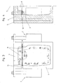
- the embodiment of the illustrated in FIGS. 1 to 8 mold half 1 of a blow mold for Embodiment of the method according to the invention has two means of piston-cylinder units 2 mutually movable moldings 3, 4.
- the lower Molded part 3 arranged stationary, for which purpose it is fixed to a platen 5 is, while the upper mold part 4 as a displaceable by means of the piston-cylinder units 2 Slider is executed.
- both mold parts 3, 4 slidably store.
- other drive means could be used be provided.
- the other mold half not shown in the figures for example, substantially be formed mirror image of the illustrated mold half 1.
- appropriate Engagement projections (not shown in the figures) on the mold parts 3, 4 of a mold half 1 in the closed state of the two mold halves in recesses in the other Mold half intervene, whereby the movement of the movable mold parts 4 synchronized becomes.
- the mold half 1 is limited together with the other, not shown in the figures Mold half a mold cavity.
- the mold cavity has a main area 8, which in the collapsed Condition of the two mold parts 3, 4 starting from the mold parting plane 7 Recesses in the mold halves 1 is formed, and one facing each other frontal surfaces 9, 10 of the molded parts 3, 4 lying lateral extension 11.
- Das Volume of the lateral extension 11 in the contracted state of the two moldings 3, 4 is preferably at least less than half the volume of the lateral extension 11 in the disassembled state of the two mold parts 3, 4th
- the opening and closing direction of the two mold halves is shown in Fig. 2 by the double arrow 12 indicated. In this case, one or both mold halves can be movable.
- the direction of displacement between the two mold parts 3, 4 (in the illustrated embodiment of the molding 4 with respect to the molded part 3) is represented by the double arrow 13.
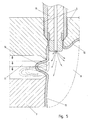
- the hose will be there inflated and abuts the walls of the main area 8 of the mold cavity. Furthermore, begins a protuberance or bulge 16 of the tube in the lateral extension 11 extend into it. This bulge 16 extends around the entire circumference of the Hose (since in the illustrated embodiment, the lateral extension 11 to the entire Circumference of the main area 8 extends).
- Fig. 5 When, for example, the shape of the hose shown in FIG. 5 with solid lines is reached is, the collapse of the molded parts 3, 4 is started.
- the pressure inside the hose 15 can be maintained here or blowing medium can be injected further.
- Fig. 5 are two intermediate steps between the extended position and the fully contracted position indicated by dashed lines, the each associated form of the hose is also indicated by dashed lines.
- Fig. 7 finally shows the fully collapsed position of the two mold parts 3, 4.
- the opposite upper and lower portions of the in the lateral extension 11th projecting bulge 16 of the tube 15 are hereby approximately complete have been compressed and form in this section of the circumferential extent of the Bulge 16 a piece of rubbish, also called Butzen. From Fig. 7 it can be seen that the in the compressed protrusion 16 of the tube 15 on its from the main area 8 of the Mold cavity remote side a clearance 18, i. one not with plastic material filled area adjacent to the lateral extension 11.
- the main area 8 of the mold cavity limit, fitting part of the tube 15 forms the hollow body wall 17 of the produced Hollow body.
- the pinch edges 21 already completely remove the piece of waste Disconnect hollow body. Instead of pinch edges 21 on both end faces 9, 10 would also be a squish only on one of these two surfaces conceivable and possible.
- the hollow body wall 17 is present only a very small accumulation of material.
- the Thickness of the hollow body wall 17 in the region of the seam 23 at least less than twice as thick as in the areas remote from the seam 23.
- FIGS. 5 and 7 represent the section of FIG. 1 and FIG. 3 on the left side Form half 1 in the region of the lateral extension 11, while Figs. 6 and 8 the in FIG. 1 and Fig. 3 located on the right side portion of the mold half 1 in the region of the lateral Extension 11 show schematically, again in the manufacture of a hollow body.
- Fig. 6 in turn, the disassembled state of the two mold parts 3, 4th with the already in the lateral extension 11 reaching bulge 16 having Hose 15 shown, wherein in the sequence, the two mold parts 3, 4 are moved together, as shown again by the dashed lines.
- the fully merged Condition of the two mold halves is shown in Fig. 8.
- the free spaces 18 extend to the outside of the Mold halves 1, so are open to the outside.
- the open spaces could also be from one Wall of the mold half 1 limited (to which during any of the steps of the process Applies plastic material).
- the rectilinear course of the free spaces 18 could These also have a different course.
- the Free space does not extend on the side facing away from the main area 8 side of the bulge, but in Fig. 7 or 8, for example, above or below a piece of debris of the bulge lies.
- it would be in the collapsed Position of the molded part 3, 4, the free space within the 16 enclosed by the bulge Provide area, i.
- the bulge 16 then has a corresponding large cavity whose extent preferably in all directions at least the Half the thickness of the wall thickness of the bulge is. However, it is preferred that at least on a border adjacent to the bulge, i. outside the area enclosed by her Area lying free space is provided. This space should preferably on the entire circumferential extent of the bulge 16 and the lateral extension 11 of the Form cavity extend.
- the distance between the frontal side Surfaces 9, 10 of the mold parts 3, 4, between which the lateral extension 11 is located at least partially smaller than the displacement between the divergent and the contracted position.
- the distance between the frontal Surfaces 9, 10 in the retracted position at least partially less than half as big as in the retracted position.
- Fig. 9 shows a two mirror-image mold halves according to FIGS. 1 to 8 produced Hollow body in the form of a canister, the waste pieces are not yet removed. After removing these debris, the canister has freestanding handles 26, 31 which are in be formed as described. In the area of these handles 26, 31 has the hollow body wall Recesses, so that the handles 26, 31 does not over the outer contour of the hollow body protrude but lie within it. From Fig. 9 it can also be seen that the outer edges of the waste pieces have an irregular course (due to the to them subsequent free spaces 18 in the production). Preferably, one around the entire Scope of the hollow body extending waste piece with an irregular outer Edge formed, which either in the manufacture by the pinch edges of the moldings 3, 4 or separated after demolding.
- FIG. 1 A similar embodiment is shown in FIG.
- the two moldings border 3, 4 in the contracted state not in a plane to each other, but the dividing line between the two mold parts 3, 4 has mutually inclined surfaces, as from the sloping portions of the seam 23 can be seen.
- the advantages of the invention are in particular the substantial reduction of irregular Material accumulations in the hollow body wall. It's becoming a regular one Seam 23 formed.
- Mold halves 1 also several pairs of mutually displaceable mold parts 3, 4 have.
Landscapes
- Engineering & Computer Science (AREA)
- Manufacturing & Machinery (AREA)
- Mechanical Engineering (AREA)
- Moulds For Moulding Plastics Or The Like (AREA)
- Blow-Moulding Or Thermoforming Of Plastics Or The Like (AREA)
Abstract
Description
- Fig. 1
- eine Ansicht einer Formhälfte einer Blasform in der auseinandergefahrenen Stellung der beiden Formteile;
- Fig. 2
- einen Schnitt entlang der Linie A-A von Fig. 1;
- Fig. 3
- eine Ansicht entsprechend Fig. 1 in der zusammengefahrenen Stellung der beiden Formteile;
- Fig. 4
- einen Schnitt entsprechend Fig. 2 in der zusammengefahrenen Stellung der beiden Formteile;
- Fig. 5
- eine Teildarstellung in einem Schnitt entlang der Linie B-B von Fig. 2, wobei der Blasdorn und der in den Formhohlraum eingebrachte Schlauch schematisch dargestellt sind;
- Fig. 6
- eine weiteren Teildarstellung in einem Schnitt entlang der Linie B-B von Fig. 2;
- Fig. 7
- einen Schnitt entsprechend Fig. 5, aber im zusammengefahrenen Zustand der beiden Formteile;
- Fig. 8
- einen Schnitt entsprechend Fig. 6, aber im zusammengefahrenen Zustand der beiden Formteile;
- Fig. 9
- eine perspektivische Darstellung eines mit einem erfindungsgemäßen Hohlkörperblasverfahren hergestellten Behälters;
- Fig.10
- ein weiteres Ausführungsbeispiel eines solchen Behälters.
- 1
- Formhälfte
- 2
- Kolben-Zylinder-Einheit
- 3
- Formteil
- 4
- Formteil
- 5
- Formaufspannplatte
- 7
- Formtrennebene
- 8
- Hauptbereich
- 9
- stirnseitige Fläche
- 10
- stirnseitige Fläche
- 11
- seitliche Erweiterung
- 12
- Öffnungs- und Schließrichtung
- 13
- Verschieberichtung
- 14
- Blasdorn
- 15
- Schlauch
- 16
- Ausbuchtung
- 17
- Hohlkörperwand
- 18
- Freiraum
- 19
- Wand
- 20
- Wand
- 21
- Quetschkante
- 22
- Steg
- 23
- Naht
- 24
- Vertiefung
- 25
- Quetschkante
- 26
- Griff
- 27
- Quetschkante
- 28
- Vertiefung
- 29
- Ausnehmung
- 30
- Hohlraum
- 31
- Griff
Claims (10)
- Hohlkörperblasverfahren zur Herstellung eines Hohlkörpers, bei welchem ein Schlauch (15) aus einem Kunststoffmaterial in eine Blasform, deren Formhälften (1) zwischen einer geöffneten Stellung und einer geschlossenen Stellung in eine Öffnungs- und Schließrichtung (12) zueinander verfahrbar sind, eingebracht wird und aufgeblasen wird, wobei zumindest eine der Formhälften (1) mindestens zwei in eine Verschieberichtung (13) senkrecht zur Öffnungs- und Schließrichtung der Formhälften (1) zwischen einer auseinandergefahrenen Stellung und einer zusammengefahrenen Stellung zueinander verfahrbare Formteile (3, 4) aufweist, die sich zunächst in ihrer auseinandergefahrenen Stellung befinden und in der Folge vor dem Öffnen der Formhälften (1) in ihre zusammengefahrene Stellung gebracht werden, wobei gegenüberliegende Abschnitte einer in eine seitliche Erweiterung (11) des Formhohlraums, welche zwischen einander zugewandten stirnseitigen Flächen (9, 10) der beiden Formteile (3, 4) liegt, sich erstreckenden Ausbuchtung (16) des Schlauchs (15) zusammengepresst werden, dadurch gekennzeichnet, dass in der zusammengefahrenen Stellung der Formteile (3, 4) ein an die in die seitliche Erweiterung (11) des Formhohlraums sich erstreckende Ausbuchtung (16) des Schlauchs (15) angrenzender oder von dieser Ausbuchtung (16) eingeschlossener Freiraum (18) innerhalb der seitlichen Erweiterung (11) freigelassen wird.
- Hohlkörperblasverfahren nach Anspruch 1, dadurch gekennzeichnet, dass der Freiraum (18) auf der vom Hauptbereich (8) des Formhohlraums abgelegenen Seite der Ausbuchtung (16) an diese angrenzt.
- Hohlkörperblasverfahren nach Anspruch 1 oder Anspruch 2, dadurch gekennzeichnet, dass zumindest ein Abschnitt der in die seitliche Erweiterung (11) sich erstreckenden Ausbuchtung (16) des Schlauchs (15) ein Abfallstück bildet.
- Hohlkörperblasverfahren nach einem der Ansprüche 1 bis 3, dadurch gekennzeichnet, dass zumindest ein Abschnitt der in die seitliche Erweiterung (11) sich erstreckenden Ausbuchtung (16) des Schlauchs (15) einen, vorzugsweise freistehenden, Griff (26, 31) des Hohlkörpers bildet.
- Hohlkörperblasverfahren nach Anspruch 4, dadurch gekennzeichnet, dass zumindest ein Abfallstück zwischen der Hohlkörperwand (17) des herzustellenden Hohlkörpers und dem Griff (26, 31) ausgebildet wird, welches in der Folge entfernt wird.
- Hohlkörperblasverfahren nach einem der Ansprüche 4 oder 5, dadurch gekennzeichnet, dass sich die seitliche Erweiterung (11) auf der vom Hauptbereich (8) des Formhohlraums abgelegenen Seite des Griffs (26, 31) weiter nach außen erstreckt.
- Hohlkörperblasverfahren nach einem der Ansprüche 1 bis 6, dadurch gekennzeichnet, dass in einem Bereich der seitlichen Erweiterung (11), in welchem an die Hohlkörperwand (17) des herzustellenden Hohlkörpers ein Abfallstück angrenzt, vorzugsweise in allen solchen Bereichen, zumindest eine der beiden einander zugewandten stirnseitigen Flächen (9, 10) der Formteile (3, 4) eine das Abfallstück an seinem Ansatz zur Hohlkörperwand (17) zusammenquetschende Quetschkante (21) aufweist.
- Hohlkörperblasverfahren nach einem der Ansprüche 1 bis 7, dadurch gekennzeichnet, dass die seitliche Erweiterung (11) sich bis zur Außenseite der Formhälfte (1) erstreckt, vorzugsweise in eine vom Hauptbereich (8) des Formhohlraums radial nach außen verlaufende Richtung.
- Hohlkörperblasverfahren nach einem der Ansprüche 1 bis 8, dadurch gekennzeichnet, dass sich der Freiraum (18) über die gesamte Umfangserstreckung der seitlichen Erweiterung (11) erstreckt.
- Blasform für ein Hohlkörperblasverfahren zur Herstellung eines Hohlkörpers aus einem aus einem Kunststoffmaterial bestehenden Schlauch, mit zwischen einer geöffneten Stellung und einer geschlossenen Stellung zueinander verfahrbaren Formhälften (1), von denen zumindest eine mindestens zwei in eine Verschieberichtung (13) senkrecht zur Öffnungs- und Schließrichtung (12) der Formhälften (1) zwischen einer auseinandergefahrenen Stellung und einer zusammengefahrenen Stellung gegeneinander verfahrbare Formteile (3, 4) aufweist, wobei der Formhohlraum eine zwischen stirnseitigen Flächen (8, 9) der Formteile (3, 4) liegende seitliche Erweiterung zur Aufnahme einer Ausbuchtung (16) des Schlauchs besitzt, dadurch gekennzeichnet, dass die seitliche Erweiterung (11) bis zur Außenseite der Formhälfte (1) verläuft, vorzugsweise in Richtung einer Geraden.
Applications Claiming Priority (2)
| Application Number | Priority Date | Filing Date | Title |
|---|---|---|---|
| AT2862004 | 2004-02-24 | ||
| AT2862004 | 2004-02-24 |
Publications (2)
| Publication Number | Publication Date |
|---|---|
| EP1579980A1 true EP1579980A1 (de) | 2005-09-28 |
| EP1579980B1 EP1579980B1 (de) | 2010-06-09 |
Family
ID=34842250
Family Applications (1)
| Application Number | Title | Priority Date | Filing Date |
|---|---|---|---|
| EP04030855A Expired - Lifetime EP1579980B1 (de) | 2004-02-24 | 2004-12-28 | Hohlkörperblasverfahren und Blasform dafür |
Country Status (3)
| Country | Link |
|---|---|
| EP (1) | EP1579980B1 (de) |
| AT (1) | ATE470555T1 (de) |
| DE (1) | DE502004011261D1 (de) |
Cited By (1)
| Publication number | Priority date | Publication date | Assignee | Title |
|---|---|---|---|---|
| WO2020007695A1 (de) * | 2018-07-05 | 2020-01-09 | Volkswagen Aktiengesellschaft | Verfahren und werkzeug zur herstellung eines kunststoffbehälters, insbesondere eines kraftstoffbehälters, durch innendruckformen |
Citations (1)
| Publication number | Priority date | Publication date | Assignee | Title |
|---|---|---|---|---|
| US4378328A (en) * | 1979-04-12 | 1983-03-29 | Mauser-Werke Gmbh | Method for making chime structure for blow molded hollow member |
-
2004
- 2004-12-28 AT AT04030855T patent/ATE470555T1/de active
- 2004-12-28 EP EP04030855A patent/EP1579980B1/de not_active Expired - Lifetime
- 2004-12-28 DE DE502004011261T patent/DE502004011261D1/de not_active Expired - Lifetime
Patent Citations (1)
| Publication number | Priority date | Publication date | Assignee | Title |
|---|---|---|---|---|
| US4378328A (en) * | 1979-04-12 | 1983-03-29 | Mauser-Werke Gmbh | Method for making chime structure for blow molded hollow member |
Cited By (2)
| Publication number | Priority date | Publication date | Assignee | Title |
|---|---|---|---|---|
| WO2020007695A1 (de) * | 2018-07-05 | 2020-01-09 | Volkswagen Aktiengesellschaft | Verfahren und werkzeug zur herstellung eines kunststoffbehälters, insbesondere eines kraftstoffbehälters, durch innendruckformen |
| US11691326B2 (en) | 2018-07-05 | 2023-07-04 | Volkswagen Aktiengesellschaft | Method and tool for manufacturing a plastic container, in particular a fuel container, by means of internal pressure forming |
Also Published As
| Publication number | Publication date |
|---|---|
| EP1579980B1 (de) | 2010-06-09 |
| DE502004011261D1 (de) | 2010-07-22 |
| ATE470555T1 (de) | 2010-06-15 |
Similar Documents
| Publication | Publication Date | Title |
|---|---|---|
| DE60123805T2 (de) | Blasgeformter behälter und verschluss sowie verfahren und vorrichtung zu dessen herstellung | |
| EP1183144B1 (de) | Verfahren zum herstellen von extrusionsblasgeformten behältern mit mindestens zwei kammern | |
| DE69327968T2 (de) | Herstellen von schweisslinienfreien, spritzgegossenen gegenständen | |
| DE60030693T2 (de) | Kompressive innenhochdruckformung | |
| DE2161066B2 (de) | Verfahren und vorrichtung zur herstellung eines hohlkoerpers aus thermoplastischem kunststoff | |
| EP0746456B1 (de) | Verfahren und vorrichtung zur herstellung von hohlkörpern aus thermoplastischen kunststoffen im blasverfahren | |
| DE1479494C3 (de) | Verfahren zur Erzeugung von min destens einer Öffnung an Hohlkörpern aus Kuststoff | |
| EP0152009B1 (de) | Deckel einer Flüssigkeitspackung mit Verfahren und Vorrichtung zur Herstellung desselben | |
| EP0256062B1 (de) | Verfahren und extrusionsblasmaschine zur herstellung von flachflaschen | |
| DE102017202839B4 (de) | Verfahren und Werkzeug zur Herstellung eines Kunststoffbehälters, insbesondere eines Kraftstoffbehälters, durch Innendruckformen | |
| EP1579980B1 (de) | Hohlkörperblasverfahren und Blasform dafür | |
| DE4142114C2 (de) | Verfahren zum Blasformen eines Kunststoffgegenstands sowie Blasformsystem | |
| EP1112164B1 (de) | Verfahren und vorrichtung zur herstellung eines grossvolumigen behälters | |
| EP0626248B1 (de) | Hohlform zur Herstellung von Hohlkörpern mit Handgriffen | |
| DE3900894A1 (de) | Verfahren zur herstellung von flaschenkaesten mit waagrechten griffholmen sowie entsprechende flaschenkaesten | |
| EP0204200B1 (de) | Verfahren und Vorrichtung zum Herstellen von Hohlkörpern aus thermoplastischem Material im Blasverfahren | |
| EP2595887B1 (de) | Verfahren und vorrichtung zum herstellen und befüllen von behältern aus thermoplastischem kunststoff | |
| DE3306469C2 (de) | Verfahren zum Herstellen eines eine Durchbrechung aufweisenden Blasformkörpers | |
| EP3291961A1 (de) | VERFAHREN UND VORRICHTUNG ZUR HERSTELLUNG GROßVOLUMIGER BEHÄLTER MIT FLANSCH DURCH KUNSTSTOFF-BLASFORMEN | |
| EP3882002B1 (de) | Verfahren zur herstellung eines kunststoff-kanisters und entsprechender blasform | |
| EP2310181B1 (de) | Mehrteiliges Blasformwerkzeug, Verfahren zur Herstellung eines Hohlkörpers, Hohlkörper, sowie Extrusionsblasmaschine | |
| DE1479275B2 (de) | Verfahren und Vorrichtung zum Abtren nen von Abfallstucken beim Herstellen von Hohlkörpern aus thermoplastischem Kunststoff im Blasverfahren | |
| DE3828994C2 (de) | Werkzeug und Verfahren zur Herstellung technischer Hohlkörper durch Extrusionsblasen | |
| DE102018204145A1 (de) | Verfahren und Werkzeug zur Herstellung eines Kunststoffbehälters, insbesondere eines Kraftstoffbehälters, durch Innendruckformen | |
| EP3515682B1 (de) | Extrusionsblasgeformter behälter sowie verfahren und blasformwerkzeug zu dessen herstellung |
Legal Events
| Date | Code | Title | Description |
|---|---|---|---|
| PUAI | Public reference made under article 153(3) epc to a published international application that has entered the european phase |
Free format text: ORIGINAL CODE: 0009012 |
|
| AK | Designated contracting states |
Kind code of ref document: A1 Designated state(s): AT BE BG CH CY CZ DE DK EE ES FI FR GB GR HU IE IS IT LI LT LU MC NL PL PT RO SE SI SK TR |
|
| AX | Request for extension of the european patent |
Extension state: AL BA HR LV MK YU |
|
| 17P | Request for examination filed |
Effective date: 20060127 |
|
| AKX | Designation fees paid |
Designated state(s): AT BE BG CH CY CZ DE DK EE ES FI FR GB GR HU IE IS IT LI LT LU MC NL PL PT RO SE SI SK TR |
|
| 17Q | First examination report despatched |
Effective date: 20090806 |
|
| GRAP | Despatch of communication of intention to grant a patent |
Free format text: ORIGINAL CODE: EPIDOSNIGR1 |
|
| GRAS | Grant fee paid |
Free format text: ORIGINAL CODE: EPIDOSNIGR3 |
|
| GRAA | (expected) grant |
Free format text: ORIGINAL CODE: 0009210 |
|
| AK | Designated contracting states |
Kind code of ref document: B1 Designated state(s): AT BE BG CH CY CZ DE DK EE ES FI FR GB GR HU IE IS IT LI LT LU MC NL PL PT RO SE SI SK TR |
|
| REG | Reference to a national code |
Ref country code: CH Ref legal event code: EP |
|
| REG | Reference to a national code |
Ref country code: IE Ref legal event code: FG4D Free format text: LANGUAGE OF EP DOCUMENT: GERMAN |
|
| REF | Corresponds to: |
Ref document number: 502004011261 Country of ref document: DE Date of ref document: 20100722 Kind code of ref document: P |
|
| REG | Reference to a national code |
Ref country code: CH Ref legal event code: NV Representative=s name: SCHNEIDER FELDMANN AG PATENT- UND MARKENANWAELTE |
|
| REG | Reference to a national code |
Ref country code: NL Ref legal event code: VDEP Effective date: 20100609 |
|
| PG25 | Lapsed in a contracting state [announced via postgrant information from national office to epo] |
Ref country code: LT Free format text: LAPSE BECAUSE OF FAILURE TO SUBMIT A TRANSLATION OF THE DESCRIPTION OR TO PAY THE FEE WITHIN THE PRESCRIBED TIME-LIMIT Effective date: 20100609 Ref country code: SE Free format text: LAPSE BECAUSE OF FAILURE TO SUBMIT A TRANSLATION OF THE DESCRIPTION OR TO PAY THE FEE WITHIN THE PRESCRIBED TIME-LIMIT Effective date: 20100609 |
|
| LTIE | Lt: invalidation of european patent or patent extension |
Effective date: 20100609 |
|
| PG25 | Lapsed in a contracting state [announced via postgrant information from national office to epo] |
Ref country code: FI Free format text: LAPSE BECAUSE OF FAILURE TO SUBMIT A TRANSLATION OF THE DESCRIPTION OR TO PAY THE FEE WITHIN THE PRESCRIBED TIME-LIMIT Effective date: 20100609 Ref country code: SI Free format text: LAPSE BECAUSE OF FAILURE TO SUBMIT A TRANSLATION OF THE DESCRIPTION OR TO PAY THE FEE WITHIN THE PRESCRIBED TIME-LIMIT Effective date: 20100609 |
|
| PG25 | Lapsed in a contracting state [announced via postgrant information from national office to epo] |
Ref country code: GR Free format text: LAPSE BECAUSE OF FAILURE TO SUBMIT A TRANSLATION OF THE DESCRIPTION OR TO PAY THE FEE WITHIN THE PRESCRIBED TIME-LIMIT Effective date: 20100910 Ref country code: CY Free format text: LAPSE BECAUSE OF FAILURE TO SUBMIT A TRANSLATION OF THE DESCRIPTION OR TO PAY THE FEE WITHIN THE PRESCRIBED TIME-LIMIT Effective date: 20100609 Ref country code: PL Free format text: LAPSE BECAUSE OF FAILURE TO SUBMIT A TRANSLATION OF THE DESCRIPTION OR TO PAY THE FEE WITHIN THE PRESCRIBED TIME-LIMIT Effective date: 20100609 |
|
| REG | Reference to a national code |
Ref country code: IE Ref legal event code: FD4D |
|
| PG25 | Lapsed in a contracting state [announced via postgrant information from national office to epo] |
Ref country code: EE Free format text: LAPSE BECAUSE OF FAILURE TO SUBMIT A TRANSLATION OF THE DESCRIPTION OR TO PAY THE FEE WITHIN THE PRESCRIBED TIME-LIMIT Effective date: 20100609 Ref country code: NL Free format text: LAPSE BECAUSE OF FAILURE TO SUBMIT A TRANSLATION OF THE DESCRIPTION OR TO PAY THE FEE WITHIN THE PRESCRIBED TIME-LIMIT Effective date: 20100609 Ref country code: IE Free format text: LAPSE BECAUSE OF FAILURE TO SUBMIT A TRANSLATION OF THE DESCRIPTION OR TO PAY THE FEE WITHIN THE PRESCRIBED TIME-LIMIT Effective date: 20100609 |
|
| PG25 | Lapsed in a contracting state [announced via postgrant information from national office to epo] |
Ref country code: CZ Free format text: LAPSE BECAUSE OF FAILURE TO SUBMIT A TRANSLATION OF THE DESCRIPTION OR TO PAY THE FEE WITHIN THE PRESCRIBED TIME-LIMIT Effective date: 20100609 Ref country code: SK Free format text: LAPSE BECAUSE OF FAILURE TO SUBMIT A TRANSLATION OF THE DESCRIPTION OR TO PAY THE FEE WITHIN THE PRESCRIBED TIME-LIMIT Effective date: 20100609 Ref country code: RO Free format text: LAPSE BECAUSE OF FAILURE TO SUBMIT A TRANSLATION OF THE DESCRIPTION OR TO PAY THE FEE WITHIN THE PRESCRIBED TIME-LIMIT Effective date: 20100609 Ref country code: PT Free format text: LAPSE BECAUSE OF FAILURE TO SUBMIT A TRANSLATION OF THE DESCRIPTION OR TO PAY THE FEE WITHIN THE PRESCRIBED TIME-LIMIT Effective date: 20101011 Ref country code: IS Free format text: LAPSE BECAUSE OF FAILURE TO SUBMIT A TRANSLATION OF THE DESCRIPTION OR TO PAY THE FEE WITHIN THE PRESCRIBED TIME-LIMIT Effective date: 20101009 |
|
| PG25 | Lapsed in a contracting state [announced via postgrant information from national office to epo] |
Ref country code: IT Free format text: LAPSE BECAUSE OF FAILURE TO SUBMIT A TRANSLATION OF THE DESCRIPTION OR TO PAY THE FEE WITHIN THE PRESCRIBED TIME-LIMIT Effective date: 20100609 |
|
| PLBE | No opposition filed within time limit |
Free format text: ORIGINAL CODE: 0009261 |
|
| STAA | Information on the status of an ep patent application or granted ep patent |
Free format text: STATUS: NO OPPOSITION FILED WITHIN TIME LIMIT |
|
| PG25 | Lapsed in a contracting state [announced via postgrant information from national office to epo] |
Ref country code: DK Free format text: LAPSE BECAUSE OF FAILURE TO SUBMIT A TRANSLATION OF THE DESCRIPTION OR TO PAY THE FEE WITHIN THE PRESCRIBED TIME-LIMIT Effective date: 20100609 |
|
| 26N | No opposition filed |
Effective date: 20110310 |
|
| BERE | Be: lapsed |
Owner name: FRIEDRICH H. WEISCHEDE FORMENBAU G.M.B.H. Effective date: 20101231 Owner name: FRIES PLANUNGS- UND MARKETINGGESELLSCHAFT M.B.H. Effective date: 20101231 |
|
| REG | Reference to a national code |
Ref country code: DE Ref legal event code: R097 Ref document number: 502004011261 Country of ref document: DE Effective date: 20110309 |
|
| PG25 | Lapsed in a contracting state [announced via postgrant information from national office to epo] |
Ref country code: MC Free format text: LAPSE BECAUSE OF NON-PAYMENT OF DUE FEES Effective date: 20101231 |
|
| GBPC | Gb: european patent ceased through non-payment of renewal fee |
Effective date: 20101228 |
|
| PG25 | Lapsed in a contracting state [announced via postgrant information from national office to epo] |
Ref country code: BE Free format text: LAPSE BECAUSE OF NON-PAYMENT OF DUE FEES Effective date: 20101231 |
|
| PG25 | Lapsed in a contracting state [announced via postgrant information from national office to epo] |
Ref country code: GB Free format text: LAPSE BECAUSE OF NON-PAYMENT OF DUE FEES Effective date: 20101228 |
|
| PG25 | Lapsed in a contracting state [announced via postgrant information from national office to epo] |
Ref country code: BG Free format text: LAPSE BECAUSE OF FAILURE TO SUBMIT A TRANSLATION OF THE DESCRIPTION OR TO PAY THE FEE WITHIN THE PRESCRIBED TIME-LIMIT Effective date: 20100609 Ref country code: LU Free format text: LAPSE BECAUSE OF NON-PAYMENT OF DUE FEES Effective date: 20101228 Ref country code: HU Free format text: LAPSE BECAUSE OF FAILURE TO SUBMIT A TRANSLATION OF THE DESCRIPTION OR TO PAY THE FEE WITHIN THE PRESCRIBED TIME-LIMIT Effective date: 20101210 |
|
| PG25 | Lapsed in a contracting state [announced via postgrant information from national office to epo] |
Ref country code: TR Free format text: LAPSE BECAUSE OF FAILURE TO SUBMIT A TRANSLATION OF THE DESCRIPTION OR TO PAY THE FEE WITHIN THE PRESCRIBED TIME-LIMIT Effective date: 20100609 |
|
| PG25 | Lapsed in a contracting state [announced via postgrant information from national office to epo] |
Ref country code: BG Free format text: LAPSE BECAUSE OF FAILURE TO SUBMIT A TRANSLATION OF THE DESCRIPTION OR TO PAY THE FEE WITHIN THE PRESCRIBED TIME-LIMIT Effective date: 20100909 |
|
| PG25 | Lapsed in a contracting state [announced via postgrant information from national office to epo] |
Ref country code: ES Free format text: LAPSE BECAUSE OF FAILURE TO SUBMIT A TRANSLATION OF THE DESCRIPTION OR TO PAY THE FEE WITHIN THE PRESCRIBED TIME-LIMIT Effective date: 20100920 |
|
| REG | Reference to a national code |
Ref country code: FR Ref legal event code: PLFP Year of fee payment: 12 |
|
| REG | Reference to a national code |
Ref country code: DE Ref legal event code: R082 Ref document number: 502004011261 Country of ref document: DE Representative=s name: VKK PATENTANWAELTE, DE Ref country code: DE Ref legal event code: R082 Ref document number: 502004011261 Country of ref document: DE Representative=s name: VONNEMANN KLOIBER & KOLLEGEN, DE Ref country code: DE Ref legal event code: R081 Ref document number: 502004011261 Country of ref document: DE Owner name: FRIES PLANUNGS- UND MARKETINGGESELLSCHAFT M.B., AT Free format text: FORMER OWNERS: FRIES PLANUNGS- UND MARKETINGGESELLSCHAFT M.B.H., SULZ, AT; FRIEDRICH H. WEISCHEDE FORMENBAU GMBH, 46242 BOTTROP, DE Ref country code: DE Ref legal event code: R081 Ref document number: 502004011261 Country of ref document: DE Owner name: FHW-MOULDS GMBH, DE Free format text: FORMER OWNERS: FRIES PLANUNGS- UND MARKETINGGESELLSCHAFT M.B.H., SULZ, AT; FRIEDRICH H. WEISCHEDE FORMENBAU GMBH, 46242 BOTTROP, DE Ref country code: DE Ref legal event code: R082 Ref document number: 502004011261 Country of ref document: DE Representative=s name: VKK PATENTANWAELTE PARTG MBB, DE |
|
| REG | Reference to a national code |
Ref country code: CH Ref legal event code: PUEA Owner name: FRIES PLANUNGS- UND MARKETINGGESELLSCHAFT M.B., DE Free format text: FORMER OWNER: FRIEDRICH H. WEISCHEDE FORMENBAU GMBH, AT |
|
| REG | Reference to a national code |
Ref country code: FR Ref legal event code: TQ Owner name: FHW-MOULDS GMBH, DE Effective date: 20160609 Ref country code: FR Ref legal event code: TQ Owner name: FRIES PLANUNGS- UNDMARKETINGGESELLSCHAFT M.B.H, AT Effective date: 20160609 |
|
| REG | Reference to a national code |
Ref country code: AT Ref legal event code: PC Ref document number: 470555 Country of ref document: AT Kind code of ref document: T Owner name: FHW-MOULDS GMBH, DE Effective date: 20160831 Ref country code: AT Ref legal event code: PC Ref document number: 470555 Country of ref document: AT Kind code of ref document: T Owner name: FRIES PLANUNGS- UND MARKETINGGESELLSCHAFT M.B., AT Effective date: 20160831 |
|
| REG | Reference to a national code |
Ref country code: FR Ref legal event code: PLFP Year of fee payment: 13 |
|
| REG | Reference to a national code |
Ref country code: FR Ref legal event code: PLFP Year of fee payment: 14 |
|
| REG | Reference to a national code |
Ref country code: CH Ref legal event code: PFA Owner name: FRIES PLANUNGS- UND MARKETINGGESELLSCHAFT M.B., DE Free format text: FORMER OWNER: FRIES PLANUNGS- UND MARKETINGGESELLSCHAFT M.B.H., DE |
|
| PGFP | Annual fee paid to national office [announced via postgrant information from national office to epo] |
Ref country code: FR Payment date: 20231226 Year of fee payment: 20 Ref country code: AT Payment date: 20231211 Year of fee payment: 20 |
|
| PGFP | Annual fee paid to national office [announced via postgrant information from national office to epo] |
Ref country code: CH Payment date: 20240101 Year of fee payment: 20 |
|
| PGFP | Annual fee paid to national office [announced via postgrant information from national office to epo] |
Ref country code: DE Payment date: 20240429 Year of fee payment: 20 |
|
| REG | Reference to a national code |
Ref country code: DE Ref legal event code: R071 Ref document number: 502004011261 Country of ref document: DE |
|
| REG | Reference to a national code |
Ref country code: CH Ref legal event code: PL |
|
| REG | Reference to a national code |
Ref country code: AT Ref legal event code: MK07 Ref document number: 470555 Country of ref document: AT Kind code of ref document: T Effective date: 20241228 |