EP1579902B1 - Vorrichtung zum Entzug von Sauerstoff im Kraftstoff - Google Patents
Vorrichtung zum Entzug von Sauerstoff im Kraftstoff Download PDFInfo
- Publication number
- EP1579902B1 EP1579902B1 EP05251812A EP05251812A EP1579902B1 EP 1579902 B1 EP1579902 B1 EP 1579902B1 EP 05251812 A EP05251812 A EP 05251812A EP 05251812 A EP05251812 A EP 05251812A EP 1579902 B1 EP1579902 B1 EP 1579902B1
- Authority
- EP
- European Patent Office
- Prior art keywords
- fuel
- oxygen
- membrane
- recited
- gas
- Prior art date
- Legal status (The legal status is an assumption and is not a legal conclusion. Google has not performed a legal analysis and makes no representation as to the accuracy of the status listed.)
- Expired - Lifetime
Links
- 239000000446 fuel Substances 0.000 title claims abstract description 163
- 238000006392 deoxygenation reaction Methods 0.000 title abstract description 11
- QVGXLLKOCUKJST-UHFFFAOYSA-N atomic oxygen Chemical compound [O] QVGXLLKOCUKJST-UHFFFAOYSA-N 0.000 claims abstract description 76
- 239000001301 oxygen Substances 0.000 claims abstract description 76
- 229910052760 oxygen Inorganic materials 0.000 claims abstract description 76
- 239000012528 membrane Substances 0.000 claims abstract description 72
- 239000007789 gas Substances 0.000 claims description 58
- 239000011148 porous material Substances 0.000 claims description 15
- 238000000034 method Methods 0.000 claims description 9
- 239000007788 liquid Substances 0.000 claims description 5
- 239000011261 inert gas Substances 0.000 claims description 2
- 238000006243 chemical reaction Methods 0.000 abstract description 3
- IJGRMHOSHXDMSA-UHFFFAOYSA-N Atomic nitrogen Chemical compound N#N IJGRMHOSHXDMSA-UHFFFAOYSA-N 0.000 description 8
- 238000009792 diffusion process Methods 0.000 description 6
- 238000010586 diagram Methods 0.000 description 5
- 239000004215 Carbon black (E152) Substances 0.000 description 4
- 230000008901 benefit Effects 0.000 description 4
- 238000004939 coking Methods 0.000 description 4
- 239000002826 coolant Substances 0.000 description 4
- 238000009826 distribution Methods 0.000 description 4
- 229930195733 hydrocarbon Natural products 0.000 description 4
- 150000002430 hydrocarbons Chemical class 0.000 description 4
- 229910052757 nitrogen Inorganic materials 0.000 description 4
- 238000002485 combustion reaction Methods 0.000 description 3
- 230000003247 decreasing effect Effects 0.000 description 3
- 239000008246 gaseous mixture Substances 0.000 description 3
- 239000000571 coke Substances 0.000 description 2
- 230000004907 flux Effects 0.000 description 2
- 239000002737 fuel gas Substances 0.000 description 2
- 238000010438 heat treatment Methods 0.000 description 2
- 230000006872 improvement Effects 0.000 description 2
- 238000012986 modification Methods 0.000 description 2
- 230000004048 modification Effects 0.000 description 2
- 239000004809 Teflon Substances 0.000 description 1
- 229920006362 Teflon® Polymers 0.000 description 1
- 238000006701 autoxidation reaction Methods 0.000 description 1
- 230000004888 barrier function Effects 0.000 description 1
- 230000015572 biosynthetic process Effects 0.000 description 1
- 230000005587 bubbling Effects 0.000 description 1
- 239000006227 byproduct Substances 0.000 description 1
- 230000007547 defect Effects 0.000 description 1
- 230000001627 detrimental effect Effects 0.000 description 1
- 238000004090 dissolution Methods 0.000 description 1
- 230000000694 effects Effects 0.000 description 1
- 230000002349 favourable effect Effects 0.000 description 1
- 239000000295 fuel oil Substances 0.000 description 1
- 238000002347 injection Methods 0.000 description 1
- 239000007924 injection Substances 0.000 description 1
- 239000003350 kerosene Substances 0.000 description 1
- 238000004519 manufacturing process Methods 0.000 description 1
- 230000005499 meniscus Effects 0.000 description 1
- 238000007254 oxidation reaction Methods 0.000 description 1
- 238000010926 purge Methods 0.000 description 1
- 238000007348 radical reaction Methods 0.000 description 1
- 150000003254 radicals Chemical class 0.000 description 1
- 230000009467 reduction Effects 0.000 description 1
- 230000006641 stabilisation Effects 0.000 description 1
- 238000011105 stabilization Methods 0.000 description 1
- 230000000087 stabilizing effect Effects 0.000 description 1
- 229910001220 stainless steel Inorganic materials 0.000 description 1
- 239000010935 stainless steel Substances 0.000 description 1
Images

Classifications
-
- B—PERFORMING OPERATIONS; TRANSPORTING
- B01—PHYSICAL OR CHEMICAL PROCESSES OR APPARATUS IN GENERAL
- B01D—SEPARATION
- B01D19/00—Degasification of liquids
-
- B—PERFORMING OPERATIONS; TRANSPORTING
- B01—PHYSICAL OR CHEMICAL PROCESSES OR APPARATUS IN GENERAL
- B01D—SEPARATION
- B01D19/00—Degasification of liquids
- B01D19/0031—Degasification of liquids by filtration
-
- B—PERFORMING OPERATIONS; TRANSPORTING
- B01—PHYSICAL OR CHEMICAL PROCESSES OR APPARATUS IN GENERAL
- B01D—SEPARATION
- B01D61/00—Processes of separation using semi-permeable membranes, e.g. dialysis, osmosis or ultrafiltration; Apparatus, accessories or auxiliary operations specially adapted therefor
-
- C—CHEMISTRY; METALLURGY
- C10—PETROLEUM, GAS OR COKE INDUSTRIES; TECHNICAL GASES CONTAINING CARBON MONOXIDE; FUELS; LUBRICANTS; PEAT
- C10G—CRACKING HYDROCARBON OILS; PRODUCTION OF LIQUID HYDROCARBON MIXTURES, e.g. BY DESTRUCTIVE HYDROGENATION, OLIGOMERISATION, POLYMERISATION; RECOVERY OF HYDROCARBON OILS FROM OIL-SHALE, OIL-SAND, OR GASES; REFINING MIXTURES MAINLY CONSISTING OF HYDROCARBONS; REFORMING OF NAPHTHA; MINERAL WAXES
- C10G31/00—Refining of hydrocarbon oils, in the absence of hydrogen, by methods not otherwise provided for
- C10G31/11—Refining of hydrocarbon oils, in the absence of hydrogen, by methods not otherwise provided for by dialysis
-
- F—MECHANICAL ENGINEERING; LIGHTING; HEATING; WEAPONS; BLASTING
- F02—COMBUSTION ENGINES; HOT-GAS OR COMBUSTION-PRODUCT ENGINE PLANTS
- F02C—GAS-TURBINE PLANTS; AIR INTAKES FOR JET-PROPULSION PLANTS; CONTROLLING FUEL SUPPLY IN AIR-BREATHING JET-PROPULSION PLANTS
- F02C7/00—Features, components parts, details or accessories, not provided for in, or of interest apart form groups F02C1/00 - F02C6/00; Air intakes for jet-propulsion plants
- F02C7/22—Fuel supply systems
- F02C7/224—Heating fuel before feeding to the burner
-
- B—PERFORMING OPERATIONS; TRANSPORTING
- B01—PHYSICAL OR CHEMICAL PROCESSES OR APPARATUS IN GENERAL
- B01D—SEPARATION
- B01D19/00—Degasification of liquids
- B01D19/0005—Degasification of liquids with one or more auxiliary substances
-
- F—MECHANICAL ENGINEERING; LIGHTING; HEATING; WEAPONS; BLASTING
- F23—COMBUSTION APPARATUS; COMBUSTION PROCESSES
- F23K—FEEDING FUEL TO COMBUSTION APPARATUS
- F23K2900/00—Special features of, or arrangements for fuel supplies
- F23K2900/05082—Removing gaseous substances from liquid fuel line, e.g. oxygen
Definitions
- the present invention relates to stabilizing fuel by deoxygenation, and more particularly to deoxygenation through a self-supporting porous membrane adjacent an oxygen receiving channel.
- Jet fuel is often utilized in aircraft as a coolant for various aircraft systems.
- the presence of dissolved oxygen in hydrocarbon jet fuels may be objectionable because the oxygen supports oxidation reactions that yield undesirable by-products.
- Dissolution of air in jet fuel results in an approximately 70 ppm oxygen concentration.
- aerated fuel is heated between 350°F (177°C) and 850°F (454°C) the oxygen initiates free radical reactions of the fuel resulting in deposits commonly referred to as "coke” or "coking.” Coke may be detrimental to the fuel lines and may inhibit combustion. The formation of such deposits may impair the normal functioning of a fuel system, either with respect to an intended heat exchange function or the efficient injection of fuel.
- FSU Fuel Stabilization Unit
- One conventional Fuel Stabilization Unit (FSU) utilized in aircraft removes oxygen from jet fuel by producing an oxygen pressure gradient across a membrane permeable to oxygen.
- the gradient is produced by vacuum on one side of the membrane.
- the membrane is supported on a porous stainless steel backing plate, which is relatively expensive to manufacture and may be a diffusion barrier requiring a relative increase in the FSU size.
- the membrane is relatively thin ( ⁇ 2-5 microns) and lacks mechanical integrity, hence the porous backing.
- Mechanical pumps and vacuum housings are also required to generate the pressure gradient which further increases the size and weight of the FSU.
- Such thin membranes (2-5 microns) may have defects and pin-holes. Fuel may then seep through the membrane and accumulating in the backing which results in further resistance to deoxygenation.
- US 6709492 and US 6315815 discloses a deoxygenator having the features of the preamble to claim 1.
- a fuel system is provided in accordance with the present invention as set forth in claim 1.
- a sweep gas and/or vacuum maintains an oxygen concentration differential across the membrane to deoxygenate the fuel.
- a fuel condenser is incorporated down stream of a nitrogen bleed to recover any fuel carried away by the sweep gas.
- oxygen is removed in multiple stages which operates at sequentially elevated fuel temperatures as the fuel is utilized as a coolant for a multiple of heat exchange subsystems.
- Also provided in accordance with the present invention is a method of minimizing dissolved oxygen from within a fuel system as set forth in claim 14.
- the present invention therefore provides, at least in its preferred embodiments, a method and system for the deoxygenation of hydrocarbon fuel in an inexpensive, size and weight efficient system that avoids the relatively heavy machinery required to produce a vacuum across a relatively thin membrane.
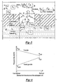
- FIG. 1 illustrates a general schematic view of a fuel system 10 for an energy conversion device (ECD) 12.
- a deoxygenator system 14 receives liquid fuel F from a reservoir 16.
- the fuel F is typically a hydrocarbon such as jet fuel.
- the ECD 12 may exist in a variety of forms in which the fuel, at some point prior to eventual use for processing, for combustion or for some form of energy release, acquires sufficient heat to support autoxidation reactions and coking if dissolved oxygen is present to any significant extent in the fuel.
- ECD 12 is a gas turbine engine, and particularly such engines in high performance aircraft.
- the fuel also serves as a coolant for one or more sub-systems in the aircraft, and in any event becomes heated as it is delivered to fuel injectors immediately prior to combustion.
- a heat exchange section 18 represents a system through which the fuel passes in a heat exchange relationship. It should be understood that the heat exchange section 18 may be directly associated with the ECD 12 and/or distributed elsewhere in the larger system.
- the heat exchange system 18 may alternatively or additionally include a multiple of heat exchanges distributed throughout the system.
- fuel F stored in the reservoir 16 normally contains dissolved oxygen, possibly at a saturation level of 70 ppm.
- a fuel pump 20 draws the fuel F from the reservoir 16.
- the fuel pump 20 communicates with the reservoir 16 via a fuel reservoir conduit 22 and a valve 24 to a fuel inlet 26 of the deoxygenator system 14.
- the pressure applied by pump 20 assists in circulating the fuel F through the deoxygenator system 14 and other portions of the fuel system 10.
- oxygen is selectively removed into a sweep gas system 28.
- the deoxygenated fuel Fd flows from a fuel outlet 30 of the deoxygenation system 14 via a deoxygenated fuel conduit 32, to the heat exchange system 18 and to the ECD 12 such as the fuel injectors of a gas turbine engine.
- a portion of the deoxygenated fuel may be recirculated, as represented by recirculation conduit 33 to either the deoxygenation system 14 and/or the reservoir 16.
- the deoxygenator system 14 preferably includes a gas/fuel contactor 34 with a self-supporting Oxygen permeable porous membrane 36 between a fuel channel 38 and an oxygen receiving channel such as a sweep gas channel 40.
- the sweep gas channel 40 preferably contains nitrogen and/or another inert gas. It should be understood that the channels may be of various shapes and arrangements to provide a pressure differential, which maintains an oxygen concentration differential across the membrane to deoxygenate the fuel.
- the fuel and the sweep gas preferably flow in opposite directions.
- U is the velocity
- C O2 is the Oxygen concentration in the fuel
- L is the thickness of the channel/layer
- Z is the length of the channel
- P is the pressure.
- the subscripts or superscripts, s refers to sweep gas, f to the fuel, in to flow inlet, out to the flow outlet, and m to the membrane 36.
- the movement of the sweep gas (e.g. N 2 ) within the sweep gas channel 40 maintains a concentration differential across the membrane 36 ( Figure 3 ).
- D O2 is the diffusion coefficient of oxygen in the sweep gas
- C O2 is the Oxygen concentration
- L m is the thickness of the porous membrane
- Z is the length of the channel
- b is the width of the channel
- H fuel-N2 is the thermodynamic distribution coefficient between fuel and sweep gas (N 2 ).
- the subscript m refers to the membrane while superscript s refers to sweep gas and f to the fuel. It is assumed that the concentration of oxygen in the sweep gas is negligible.
- L m ⁇ is the thickness of the membrane
- H fuel-membrane is the thermodynamic distribution coefficient between fuel and membrane.
- the potential improvement in deoxygenation performance, in a case when transport through the membrane is limiting is / D m L m ⁇ ⁇ H fuel - membrane D O ⁇ 2 ⁇ ⁇ m ⁇ ⁇ L m ⁇ H fuel - N ⁇ 2 ⁇ 100.
- Diffusion coefficient of oxygen in the membrane is more than 3 orders magnitude lower than that of the diffusion coefficient of oxygen in a sweep gas like N 2 .
- Preferred embodiments of the present invention utilize a porous membrane with a thickness ( Figure 3 ) that is an order of magnitude greater than the heretofore utilized thin non-porous membrane.
- the ratio of the distribution coefficients H fuel-N2 / H fuel-membrane is typically less than 1, indicating an improvement in performance with the porous membrane 36 of the present invention.
- the membrane 36 includes a multiple of pores 42 (one shown). Two basic paths for Oxygen removal from the fuel are: 1) through the membrane 36 sweep gas interface; and 2) through fuel-sweep gas interface within a pore 42. Normally, the latter is the least resistance path.
- P is the pressure.
- the subscripts s refers to sweep gas, f to the fuel, in to the flow inlet and out to the flow outlet.
- C O2 is the Oxygen concentration in the fuel.
- D O2 is the diffusion coefficient of oxygen in the sweep gas, L is the thickness of the channel/layer, Z is the length of the channel, b is the width of the channel, and H is the thermodynamic distribution coefficient.
- Fuel is prevented from flowing through the pores 42 of the porous membrane 36 by maintaining a pressure differential across the membrane which is lower than the capillary force of the fuel Fc in a pore 42 of radius r p .
- the pressure differential also provides a pressure on the sweep gas side which is lower than the pressure on the fuel side to prevent the sweep gas from bubbling through the pores 42 into the fuel. 0 ⁇ ⁇ ⁇ P ⁇ 2 ⁇ ⁇ Cos ⁇ r p
- the surface tension ⁇ of kerosene is 25 dynes/cm or 0.025 Nm -1 .
- the contact angle ⁇ is ⁇ 140° for JP-8 on Teflon AF-2400 membrane, and for a maximum pore radius of r p of 1 micron, a pressure differential of 10 kPa will prevent fuel from leaking to the sweep gas.
- the contact angle between the fuel and the porous membrane is preferably non perpendicular. Most preferably, the contact angle ⁇ is greater than 90°.
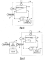
- a deoxygenator system 14A includes a gas/fuel contactor 34A between a fuel circuit and a sweep gas circuit.
- the fuel flows cocurrent or counter-current to the sweep-gas.
- the sweep gas containing relatively higher amounts of oxygen after the gas/fuel contactor 34A is purged of oxygen through a recycle blower 44 and a purge system 48 such that pure nitrogen is added to the sweep gas circuit from a sweep gas reservoir 46 to maintain low concentrations of oxygen ( C s O2 ) back into the gas/fuel contactor 34A.
- a deoxygenator system 14B includes a gas/fuel contactor 34B between the fuel circuit and a sweep gas circuit.
- the sweep gas may absorb fuel that leaks through the membrane 36.
- a nitrogen bleed 48 from the sweep gas circuit is condensed in a fuel condenser system 50 to separate the fuel from the gaseous mixture of sweep gas and oxygen.
- the condensed fuel from the condenser system 50 is then returned to the fuel reservoir 16, while the gaseous mixture is vented.
- the gaseous mixture from the fuel condenser system 50 is sent to the sweep gas reservoir 46.
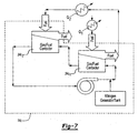
- a deoxygenator system 14C includes a multiple of gas/fuel contactors 34C1, 34C2 ... 34Cn between the fuel circuit and a sweep gas circuit.
- the gas-fuel contactors 34Cl, 34C2... 34Cn preferably operate at sequentially elevated fuel temperatures as the fuel is utilized as a coolant for a multiple of heat exchange sections Q1, Q2...Qn such as fuel-oil heat exchange subsystems along the fuel circuit.
- Elevated fuel temperature facilitates oxygen removal by decreasing the solubility of oxygen (decreasing H fuel-N2 ) in the fuel and increasing diffusion coefficient of oxygen in the fuel/membrane ( D O 2 , D m ), hence providing higher driving force for removal of oxygen and/or a lower volume system.
- Elevated fuel temperatures directly translate to a decrease in the gas-fuel contactor volume, due to favorable thermodynamic effects which are generally proportional to the operating temperature of the fuel.
- Fuel heating at a multiple of heat exchange section Q1- Qn permits a multiple of in-series fuel-gas contactors 34C1, 34C2... 34Cn to enable higher fuel heating, without coking, as the oxygen content in the fuel is decreased at the end of each stage. That is, although the fuel temperature is higher after being utilized to cool an earlier heat exchange section, the higher temperature fuel requires a smaller fuel gas contactor at the next stage to achieve generally equivalent oxygen reduction.
- the fuel is thereby progressively deoxygenated and increased in temperature as the fuel flows through the fuel system.
Landscapes
- Engineering & Computer Science (AREA)
- Chemical & Material Sciences (AREA)
- Combustion & Propulsion (AREA)
- Chemical Kinetics & Catalysis (AREA)
- Oil, Petroleum & Natural Gas (AREA)
- Mechanical Engineering (AREA)
- General Engineering & Computer Science (AREA)
- Water Supply & Treatment (AREA)
- Organic Chemistry (AREA)
- General Chemical & Material Sciences (AREA)
- Separation Using Semi-Permeable Membranes (AREA)
- Degasification And Air Bubble Elimination (AREA)
- Production Of Liquid Hydrocarbon Mixture For Refining Petroleum (AREA)
- Separation By Low-Temperature Treatments (AREA)
- Feeding And Controlling Fuel (AREA)
Claims (18)
- Kraftstoffsystem, aufweisend:einen Kraftstoffkanal (38);einen Sauerstoff aufnehmenden Kanal (40), undeine sauerstoffdurchlässige Membran (36) die in Verbindung mit dem Kraftstoffkanal (38) und mit dem Sauerstoff aufnehmenden Kanal (40) steht, wobei die Membran den Durchlass von Sauerstoff durch eine Grenzfläche zwischen der Membran und dem Sauerstoff aufnehmenden Kanal (40) erlaubt; undMittel zum Aufrechterhalten eines Druckunterschieds über die Membran,dadurch gekennzeichnet, dassdie Membran weiterhin Poren aufweist, welche den Durchlass von Sauerstoff durch die Membran erlauben und die einen Radius haben, der mit dem Druckunterschied über die Membran zusammenwirkt, um eine Kraft auf den Kraftstoff in den Poren zu bewirken, die geringer als die Kapillarkraft des Kraftstoffs in den Poren ist, und dadurch zu verhindern, dass Kraftstoff durch die Poren strömt.
- Kraftstoffsystem nach Anspruch 1, wobei die sauerstoffdurchlässige poröse Membran (36) im Allgemeinen parallel zu dem Kraftstoffkanal (38) und zu dem Sauerstoff aufnehmenden Kanal (40) ist.
- Kraftstoffsystem nach Anspruch 1, wobei die sauerstoffdurchlässige poröse Membran (36) nicht rechtwinklig zu dem Kraftstoffkanal (38) ist.
- Kraftstoffsystem nach Anspruch 1, 2 oder 3, wobei der Sauerstoff aufnehmende Kanal (40) durch sich ein inertes Gas übermittelt.
- Kraftstoffsystem nach einem der vorangehenden Ansprüche, wobei der Kraftstoffkanal (38) durch sich einen flüssigen Kraftstoff übermittelt, der gelösten Sauerstoff enthält und wobei die sauerstoffdurchlässige poröse Membran (36) betriebsfähig ist, um den gelösten Sauerstoff von dem Kraftstoff zu trennen.
- Kraftstoffsystem nach einem der vorangehenden Ansprüche, wobei der Kraftstoffkanal (38) flüssigen Kraftstoff in eine erste Richtung übermittelt und der Sauerstoff aufnehmende Kanal (40) Gas in einer der ersten Richtung entgegengerichteten Richtung übermittelt.
- Kraftstoffsystem nach einem der vorangehenden Ansprüche, wobei der Sauerstoff aufnehmende Kanal (40) Spülgas enthält.
- Kraftstoffsystem nach einem der Ansprüche 1 bis 6, wobei der Sauerstoff aufnehmende Kanal (40) ein Vakuum enthält.
- Kraftstoffsystem nach einem der vorangehenden Ansprüche, zusätzlich aufweisend einen Kraftstoffkondensator (50), der in Verbindung mit dem Sauerstoff aufnehmenden Kanal (40) steht.
- Kraftstoffsystem nach einem der vorangehenden Ansprüche, zusätzlich aufweisend ein Spülgasreservoir (46), das in Verbindung mit dem Sauerstoff aufnehmenden Kanal (40) steht.
- Kraftstoffsystem nach einem der vorangehenden Ansprüche, wobei die sauerstoffdurchlässige poröse Membran (36) in einem Gas-Kraftstoff-Contactor (34C1) enthalten ist, wobei das Kraftstoffsystem zusätzlich einen zweiten Gas/Kraftstoff-Contactor (34C2) aufweist, der in Verbindung mit dem Kraftstoffkanal (38) und mit dem Sauerstoff aufnehmenden Kanal (40) steht, wobei der zweite Gas/Kraftstoff-Contactor (34C2) in Reihe mit dem Gas-Kraftstoff-Contactor (34C1) ist.
- Kraftstoffsystem nach Anspruch 11, wobei der zweite Gas/Kraftstoff-Contactor (34C2) angeordnet ist, um Kraftstoff bei einer Kraftstofftemperatur aufzunehmen, die größer als die Kraftstofftemperatur des Gas/Kraftstoff-Contactors (34C1) ist.
- Kraftstoffsystem nach einem der vorangehenden Ansprüche, wobei die sauerstoffdurchlässige poröse Membran (36) selbsttragend ist.
- Verfahren des Minimierens von gelöstem Sauerstoff aus dem Inneren eines Kraftstoffsystems mit den Schritten:(1) Anordnen einer sauerstoffdurchlässigen Membran (36) angrenzend an eine Strömung von flüssigem Kraftstoff, der gelösten Stauerstoff enthält, wobei die sauerstoffdurchlässige Membran (36) den Durchlass von Sauerstoff durch eine Grenzfläche zwischen der Membran und einem Spülgas erlaubt;(2) Aufrechterhalten eines Druckunterschieds über die Membran (36); und(3) Strömen des Spülgases entlang der sauerstoffdurchlässigen Membran (36), um den Sauerstoff durch die Membran zu ziehen;dadurch gekennzeichnet, dass
die Membran weiterhin Poren aufweist, welche den Durchlass von Sauerstoff durch die Membran erlauben und die einen Radius haben, der mit dem Druckunterschied über die Membran zusammenwirkt, um eine Kraft auf den Kraftstoff in den Poren zu bewirken, die geringer als die Kapillarkraft des Kraftstoffs in den Poren ist, und dadurch zu verhindern, dass Kraftstoff durch die Poren strömt. - Verfahren nach Anspruch 14, wobei der Schritt (3) zusätzlich den Schritt aufweist:Strömen des Gases in einer der Richtung der Strömung des flüssigen Kraftstoffs entgegengerichteten Richtung.
- Verfahren nach Anspruch 14 oder 15, wobei der Schritt (1) zusätzlich aufweist:Anordnen der sauerstoffdurchlässigen porösen Membran (36) nicht rechtwinklig zu der Kraftstoffströmung.
- Verfahren nach einem der Ansprüche 14 bis 16, wobei der Druckunterschied einen Druck auf der Spülgasseite (40) aufweist, der geringer als der Druck auf der Kraftstoffseite (38) ist.
- Verfahren nach einem der Ansprüche 14 bis 17, das zusätzlich die Schritte aufweist:Übermitteln des Spülgases zu einem Kraftstoffkondensator (50) stromabwärts der sauerstoffdurchlässigen porösen Membran (36); undKondensieren des Kraftstoffs aus dem Inneren des Spülgases.
Applications Claiming Priority (2)
| Application Number | Priority Date | Filing Date | Title |
|---|---|---|---|
| US808151 | 2004-03-24 | ||
| US10/808,151 US7153343B2 (en) | 2004-03-24 | 2004-03-24 | Fuel deoxygenation system |
Publications (2)
| Publication Number | Publication Date |
|---|---|
| EP1579902A1 EP1579902A1 (de) | 2005-09-28 |
| EP1579902B1 true EP1579902B1 (de) | 2009-02-25 |
Family
ID=34862068
Family Applications (1)
| Application Number | Title | Priority Date | Filing Date |
|---|---|---|---|
| EP05251812A Expired - Lifetime EP1579902B1 (de) | 2004-03-24 | 2005-03-23 | Vorrichtung zum Entzug von Sauerstoff im Kraftstoff |
Country Status (8)
| Country | Link |
|---|---|
| US (1) | US7153343B2 (de) |
| EP (1) | EP1579902B1 (de) |
| JP (1) | JP2005272841A (de) |
| KR (1) | KR100656871B1 (de) |
| CN (1) | CN1673034A (de) |
| AT (1) | ATE423605T1 (de) |
| CA (1) | CA2496929A1 (de) |
| DE (1) | DE602005012881D1 (de) |
Cited By (4)
| Publication number | Priority date | Publication date | Assignee | Title |
|---|---|---|---|---|
| US9656187B2 (en) | 2014-11-12 | 2017-05-23 | Honeywell International Inc. | Fuel deoxygenation system contactor-separator |
| US9687773B2 (en) | 2014-04-30 | 2017-06-27 | Honeywell International Inc. | Fuel deoxygenation and fuel tank inerting system and method |
| US9834315B2 (en) | 2014-12-15 | 2017-12-05 | Honeywell International Inc. | Aircraft fuel deoxygenation system |
| US9897054B2 (en) | 2015-01-15 | 2018-02-20 | Honeywell International Inc. | Centrifugal fuel pump with variable pressure control |
Families Citing this family (41)
| Publication number | Priority date | Publication date | Assignee | Title |
|---|---|---|---|---|
| US20050274649A1 (en) * | 2004-06-09 | 2005-12-15 | Spadaccini Louis J | Method for suppressing oxidative coke formation in liquid hydrocarbons containing metal |
| JP2008521596A (ja) * | 2004-11-30 | 2008-06-26 | ファイア テクノロジーズ、インコーポレイテッド | 接触装置および接触方法ならびにそれらの使用 |
| US7465335B2 (en) * | 2005-02-02 | 2008-12-16 | United Technologies Corporation | Fuel deoxygenation system with textured oxygen permeable membrane |
| US7435283B2 (en) * | 2005-05-18 | 2008-10-14 | United Technologies Corporation | Modular fuel stabilization system |
| US7465336B2 (en) * | 2005-06-09 | 2008-12-16 | United Technologies Corporation | Fuel deoxygenation system with non-planar plate members |
| US7537646B2 (en) * | 2005-10-11 | 2009-05-26 | United Technologies Corporation | Fuel system and method of reducing emission |
| US7615104B2 (en) * | 2005-11-03 | 2009-11-10 | United Technologies Corporation | Fuel deoxygenation system with multi-layer oxygen permeable membrane |
| US7632338B2 (en) * | 2006-10-05 | 2009-12-15 | United Technologies Corporation | Electrochemical oxygen pump for fuel stabilization unit |
| US20080098894A1 (en) * | 2006-11-01 | 2008-05-01 | Sabatino Daniel R | Acoustic degassing heat exchanger |
| US7882704B2 (en) * | 2007-01-18 | 2011-02-08 | United Technologies Corporation | Flame stability enhancement |
| US8056345B2 (en) | 2007-06-13 | 2011-11-15 | United Technologies Corporation | Hybrid cooling of a gas turbine engine |
| US20090020013A1 (en) * | 2007-07-20 | 2009-01-22 | Sloan Michael A | Membrane based deoxygenator for processing fluids |
| US8038770B2 (en) * | 2008-12-01 | 2011-10-18 | Eaton Corporation | Separator for degassing fluid |
| US8177884B2 (en) * | 2009-05-20 | 2012-05-15 | United Technologies Corporation | Fuel deoxygenator with porous support plate |
| US8388830B2 (en) | 2010-06-25 | 2013-03-05 | Uop Llc | Process for upgrading sweetened or oxygen-contaminated kerosene or jet fuel, to minimize or eliminate its tendency to polymerize or foul when heated |
| US8388740B2 (en) | 2010-10-27 | 2013-03-05 | Uop Llc | Simplified process to remove dissolved oxygen from hydrocarbon streams |
| DE102011003449B4 (de) * | 2011-02-01 | 2016-04-07 | Siemens Aktiengesellschaft | Elektrisches Gerät mit einer Kühleinrichtung umfassend eine Vorrichtung zur Verringerung der Sauerstoffkonzentration in einem Kühlmittel in einem Kühlmittelkreislauf sowie Verfahren hierfür |
| US8741029B2 (en) * | 2011-06-30 | 2014-06-03 | United Technologies Corporation | Fuel deoxygenation using surface-modified porous membranes |
| US9580185B2 (en) | 2012-01-20 | 2017-02-28 | Hamilton Sundstrand Corporation | Small engine cooled cooling air system |
| US8876946B2 (en) | 2012-04-03 | 2014-11-04 | Hamilton Sundstrand Corporation | Combined fuel stabilization unit and heat exchanger |
| GB201217332D0 (en) * | 2012-09-28 | 2012-11-14 | Rolls Royce Plc | A gas turbine engine |
| EP2969100B1 (de) | 2013-03-12 | 2018-06-13 | Rolls-Royce North American Technologies, Inc. | Deoxygenierung von flussigkeit mit gas |
| US9789972B2 (en) * | 2014-06-27 | 2017-10-17 | Hamilton Sundstrand Corporation | Fuel and thermal management system |
| GB201508702D0 (en) * | 2015-05-21 | 2015-07-01 | Rolls Royce Plc | A system and method |
| DE102016208571A1 (de) * | 2015-06-08 | 2016-12-08 | Robert Bosch Gmbh | Anordnung für die Bereitstellung von keimfreiem Wasser für Injektionszwecke |
| US10329027B2 (en) | 2016-07-15 | 2019-06-25 | Hamilton Sundstrand Corporation | Fuel deoxygenation systems |
| US20190022558A1 (en) * | 2017-07-24 | 2019-01-24 | Hamilton Sundstrand Corporation | Fuel tank de-oxygenation system |
| US10655569B2 (en) * | 2017-08-24 | 2020-05-19 | Hamilton Sundstrand Corporation | Leakage prevention systems and methods |
| CN110092001A (zh) * | 2018-01-29 | 2019-08-06 | 哈米尔顿森德斯特兰德公司 | 飞机的油箱催化惰化设备 |
| CN110092002B (zh) * | 2018-01-30 | 2024-06-18 | 哈米尔顿森德斯特兰德公司 | 飞机的油箱催化惰化设备 |
| US11078846B2 (en) | 2018-07-30 | 2021-08-03 | Hamilton Sunstrand Corporation | Fuel delivery system |
| US10994226B2 (en) | 2018-09-13 | 2021-05-04 | Hamilton Sunstrand Corporation | Fuel deoxygenation with a spiral contactor |
| US11319085B2 (en) * | 2018-11-02 | 2022-05-03 | General Electric Company | Fuel oxygen conversion unit with valve control |
| US12025054B2 (en) * | 2019-04-05 | 2024-07-02 | General Electric Company | Pump mixer separator unit |
| US10914274B1 (en) * | 2019-09-11 | 2021-02-09 | General Electric Company | Fuel oxygen reduction unit with plasma reactor |
| CN110749641A (zh) * | 2019-11-04 | 2020-02-04 | 盐城工学院 | 一种实时监测水体中硝酸盐浓度的传感器 |
| US11866182B2 (en) | 2020-05-01 | 2024-01-09 | General Electric Company | Fuel delivery system having a fuel oxygen reduction unit |
| US11906163B2 (en) * | 2020-05-01 | 2024-02-20 | General Electric Company | Fuel oxygen conversion unit with integrated water removal |
| US11773776B2 (en) * | 2020-05-01 | 2023-10-03 | General Electric Company | Fuel oxygen reduction unit for prescribed operating conditions |
| EP4015395B1 (de) * | 2020-12-16 | 2024-10-09 | Airbus Operations, S.L.U. | Flugzeug und verfahren zum betreiben eines flugzeugs mit einer lufttrennungsvorrichtung |
| EP4523916A1 (de) * | 2023-09-15 | 2025-03-19 | Seiko Epson Corporation | Flüssigkeitsspeicherabschnitt, flüssigkeitsströmungsmechanismus und flüssigkeitsausstossvorrichtung |
Family Cites Families (11)
| Publication number | Priority date | Publication date | Assignee | Title |
|---|---|---|---|---|
| JPS62204086A (ja) * | 1986-03-04 | 1987-09-08 | 株式会社エルマ、シーアール | パイプ |
| US5619855A (en) * | 1995-06-07 | 1997-04-15 | General Electric Company | High inlet mach combustor for gas turbine engine |
| US5888275A (en) * | 1996-02-26 | 1999-03-30 | Japan Gore-Tex, Inc. | Assembly for deaeration of liquids |
| JPH1193694A (ja) * | 1997-09-18 | 1999-04-06 | Toshiba Corp | ガスタービンプラント |
| US6672072B1 (en) * | 1998-08-17 | 2004-01-06 | General Electric Company | Pressure boosted compressor cooling system |
| US6315815B1 (en) * | 1999-12-16 | 2001-11-13 | United Technologies Corporation | Membrane based fuel deoxygenator |
| US6562104B2 (en) | 2000-12-19 | 2003-05-13 | Praxair Technology, Inc. | Method and system for combusting a fuel |
| JP2003327408A (ja) | 2002-05-10 | 2003-11-19 | Mitsubishi Electric Corp | 燃料処理装置およびその運転方法 |
| US6939392B2 (en) * | 2003-04-04 | 2005-09-06 | United Technologies Corporation | System and method for thermal management |
| US6709492B1 (en) * | 2003-04-04 | 2004-03-23 | United Technologies Corporation | Planar membrane deoxygenator |
| US7041154B2 (en) * | 2003-12-12 | 2006-05-09 | United Technologies Corporation | Acoustic fuel deoxygenation system |
-
2004
- 2004-03-24 US US10/808,151 patent/US7153343B2/en not_active Expired - Lifetime
-
2005
- 2005-02-11 CA CA002496929A patent/CA2496929A1/en not_active Abandoned
- 2005-03-07 KR KR1020050018514A patent/KR100656871B1/ko not_active Expired - Fee Related
- 2005-03-22 JP JP2005082725A patent/JP2005272841A/ja active Pending
- 2005-03-23 DE DE602005012881T patent/DE602005012881D1/de not_active Expired - Lifetime
- 2005-03-23 EP EP05251812A patent/EP1579902B1/de not_active Expired - Lifetime
- 2005-03-23 AT AT05251812T patent/ATE423605T1/de not_active IP Right Cessation
- 2005-03-24 CN CNA2005100591996A patent/CN1673034A/zh active Pending
Cited By (4)
| Publication number | Priority date | Publication date | Assignee | Title |
|---|---|---|---|---|
| US9687773B2 (en) | 2014-04-30 | 2017-06-27 | Honeywell International Inc. | Fuel deoxygenation and fuel tank inerting system and method |
| US9656187B2 (en) | 2014-11-12 | 2017-05-23 | Honeywell International Inc. | Fuel deoxygenation system contactor-separator |
| US9834315B2 (en) | 2014-12-15 | 2017-12-05 | Honeywell International Inc. | Aircraft fuel deoxygenation system |
| US9897054B2 (en) | 2015-01-15 | 2018-02-20 | Honeywell International Inc. | Centrifugal fuel pump with variable pressure control |
Also Published As
| Publication number | Publication date |
|---|---|
| KR100656871B1 (ko) | 2006-12-19 |
| EP1579902A1 (de) | 2005-09-28 |
| JP2005272841A (ja) | 2005-10-06 |
| US20050211096A1 (en) | 2005-09-29 |
| ATE423605T1 (de) | 2009-03-15 |
| DE602005012881D1 (de) | 2009-04-09 |
| CN1673034A (zh) | 2005-09-28 |
| CA2496929A1 (en) | 2005-09-24 |
| KR20060043440A (ko) | 2006-05-15 |
| US7153343B2 (en) | 2006-12-26 |
Similar Documents
| Publication | Publication Date | Title |
|---|---|---|
| EP1579902B1 (de) | Vorrichtung zum Entzug von Sauerstoff im Kraftstoff | |
| EP1731209B1 (de) | Vorrichtung zur Entfernung von Brennstoff-Sauerstoff mit Hilfe von nicht-flachen Platten | |
| US7431818B2 (en) | Electrochemical fuel deoxygenation system | |
| JP2007190549A (ja) | 燃料システムおよび燃料システム内の溶存酸素の低減方法 | |
| US7465335B2 (en) | Fuel deoxygenation system with textured oxygen permeable membrane | |
| US7445659B2 (en) | Ejector to reduce permeate backpressure of air separation module | |
| US7803275B2 (en) | Membrane separation process using mixed vapor-liquid feed | |
| EP1559883A2 (de) | Kühlsystem für Gasturbinen | |
| EP3446982B1 (de) | Vakuumsystem für eine kraftstoffentgasung | |
| EP1782879A1 (de) | System zum Entfernen von Sauerstoff aus Treibstoff mittels einer mehrschichtigen sauerstoffpermeablen Membran | |
| EP3446983B1 (de) | Vakuumsystem für ein brennstoffentgasungssystem | |
| EP3546372B1 (de) | Vorkühlung für kraftstoffverdampfung in verwendung mit katalytischer kraftstofftankinertisierung | |
| US10479522B2 (en) | Internal recycle reactor for catalytic inerting | |
| EP3539901B1 (de) | Inbetriebnahme eines katalytischen inertisierungsgaserzeugungssystems mit rückführung für flugzeuge | |
| EP3434752A1 (de) | Kraftstofftank-desoxygenierungssystem | |
| US20200197834A1 (en) | Composite hollow fiber membranes for jet fuel de-oxygenation | |
| US8876946B2 (en) | Combined fuel stabilization unit and heat exchanger | |
| LT et al. | Vorrichtung zum Entzug von Sauerstoff im Kraftstoff Système de déoxygénation de carburant | |
| CN111742131B (zh) | 使用膜蒸馏的按需辛烷值的机载燃料分离 | |
| EP3434347A1 (de) | Kraftstofftankdesoxygenierungssystem | |
| US20060196174A1 (en) | Catalytic fuel deoxygenation system | |
| US20200197835A1 (en) | Composite hollow fiber membranes for jet fuel de-oxygenation | |
| EP3539880A1 (de) | Kavitationsminderung in kraftstofftankinertisierungssystemen mit katalytischer oxidation | |
| WO2020132656A1 (en) | Composite hollow fiber membranes for jet fuel de-oxygenation |
Legal Events
| Date | Code | Title | Description |
|---|---|---|---|
| PUAI | Public reference made under article 153(3) epc to a published international application that has entered the european phase |
Free format text: ORIGINAL CODE: 0009012 |
|
| AK | Designated contracting states |
Kind code of ref document: A1 Designated state(s): AT BE BG CH CY CZ DE DK EE ES FI FR GB GR HU IE IS IT LI LT LU MC NL PL PT RO SE SI SK TR |
|
| AX | Request for extension of the european patent |
Extension state: AL BA HR LV MK YU |
|
| RIN1 | Information on inventor provided before grant (corrected) |
Inventor name: BURLATSKY, SERGEI F. Inventor name: LAMM, FOSTER PHILIP Inventor name: SPADACCINI, LOUIS J. Inventor name: GUMMALLA, MALLIKA |
|
| 17P | Request for examination filed |
Effective date: 20060208 |
|
| AKX | Designation fees paid |
Designated state(s): AT BE BG CH CY CZ DE DK EE ES FI FR GB GR HU IE IS IT LI LT LU MC NL PL PT RO SE SI SK TR |
|
| 17Q | First examination report despatched |
Effective date: 20060320 |
|
| GRAP | Despatch of communication of intention to grant a patent |
Free format text: ORIGINAL CODE: EPIDOSNIGR1 |
|
| GRAS | Grant fee paid |
Free format text: ORIGINAL CODE: EPIDOSNIGR3 |
|
| GRAA | (expected) grant |
Free format text: ORIGINAL CODE: 0009210 |
|
| AK | Designated contracting states |
Kind code of ref document: B1 Designated state(s): AT BE BG CH CY CZ DE DK EE ES FI FR GB GR HU IE IS IT LI LT LU MC NL PL PT RO SE SI SK TR |
|
| REG | Reference to a national code |
Ref country code: GB Ref legal event code: FG4D |
|
| REG | Reference to a national code |
Ref country code: CH Ref legal event code: EP |
|
| REG | Reference to a national code |
Ref country code: IE Ref legal event code: FG4D |
|
| REF | Corresponds to: |
Ref document number: 602005012881 Country of ref document: DE Date of ref document: 20090409 Kind code of ref document: P |
|
| PG25 | Lapsed in a contracting state [announced via postgrant information from national office to epo] |
Ref country code: FI Free format text: LAPSE BECAUSE OF FAILURE TO SUBMIT A TRANSLATION OF THE DESCRIPTION OR TO PAY THE FEE WITHIN THE PRESCRIBED TIME-LIMIT Effective date: 20090225 Ref country code: LT Free format text: LAPSE BECAUSE OF FAILURE TO SUBMIT A TRANSLATION OF THE DESCRIPTION OR TO PAY THE FEE WITHIN THE PRESCRIBED TIME-LIMIT Effective date: 20090225 Ref country code: SI Free format text: LAPSE BECAUSE OF FAILURE TO SUBMIT A TRANSLATION OF THE DESCRIPTION OR TO PAY THE FEE WITHIN THE PRESCRIBED TIME-LIMIT Effective date: 20090225 Ref country code: NL Free format text: LAPSE BECAUSE OF FAILURE TO SUBMIT A TRANSLATION OF THE DESCRIPTION OR TO PAY THE FEE WITHIN THE PRESCRIBED TIME-LIMIT Effective date: 20090225 |
|
| NLV1 | Nl: lapsed or annulled due to failure to fulfill the requirements of art. 29p and 29m of the patents act | ||
| PG25 | Lapsed in a contracting state [announced via postgrant information from national office to epo] |
Ref country code: SE Free format text: LAPSE BECAUSE OF FAILURE TO SUBMIT A TRANSLATION OF THE DESCRIPTION OR TO PAY THE FEE WITHIN THE PRESCRIBED TIME-LIMIT Effective date: 20090525 Ref country code: IS Free format text: LAPSE BECAUSE OF FAILURE TO SUBMIT A TRANSLATION OF THE DESCRIPTION OR TO PAY THE FEE WITHIN THE PRESCRIBED TIME-LIMIT Effective date: 20090625 Ref country code: PL Free format text: LAPSE BECAUSE OF FAILURE TO SUBMIT A TRANSLATION OF THE DESCRIPTION OR TO PAY THE FEE WITHIN THE PRESCRIBED TIME-LIMIT Effective date: 20090225 Ref country code: AT Free format text: LAPSE BECAUSE OF FAILURE TO SUBMIT A TRANSLATION OF THE DESCRIPTION OR TO PAY THE FEE WITHIN THE PRESCRIBED TIME-LIMIT Effective date: 20090225 |
|
| PG25 | Lapsed in a contracting state [announced via postgrant information from national office to epo] |
Ref country code: BE Free format text: LAPSE BECAUSE OF FAILURE TO SUBMIT A TRANSLATION OF THE DESCRIPTION OR TO PAY THE FEE WITHIN THE PRESCRIBED TIME-LIMIT Effective date: 20090225 |
|
| PG25 | Lapsed in a contracting state [announced via postgrant information from national office to epo] |
Ref country code: DK Free format text: LAPSE BECAUSE OF FAILURE TO SUBMIT A TRANSLATION OF THE DESCRIPTION OR TO PAY THE FEE WITHIN THE PRESCRIBED TIME-LIMIT Effective date: 20090225 Ref country code: PT Free format text: LAPSE BECAUSE OF FAILURE TO SUBMIT A TRANSLATION OF THE DESCRIPTION OR TO PAY THE FEE WITHIN THE PRESCRIBED TIME-LIMIT Effective date: 20090812 Ref country code: CZ Free format text: LAPSE BECAUSE OF FAILURE TO SUBMIT A TRANSLATION OF THE DESCRIPTION OR TO PAY THE FEE WITHIN THE PRESCRIBED TIME-LIMIT Effective date: 20090225 Ref country code: EE Free format text: LAPSE BECAUSE OF FAILURE TO SUBMIT A TRANSLATION OF THE DESCRIPTION OR TO PAY THE FEE WITHIN THE PRESCRIBED TIME-LIMIT Effective date: 20090225 Ref country code: MC Free format text: LAPSE BECAUSE OF NON-PAYMENT OF DUE FEES Effective date: 20090331 Ref country code: ES Free format text: LAPSE BECAUSE OF FAILURE TO SUBMIT A TRANSLATION OF THE DESCRIPTION OR TO PAY THE FEE WITHIN THE PRESCRIBED TIME-LIMIT Effective date: 20090605 |
|
| REG | Reference to a national code |
Ref country code: CH Ref legal event code: PL |
|
| PG25 | Lapsed in a contracting state [announced via postgrant information from national office to epo] |
Ref country code: RO Free format text: LAPSE BECAUSE OF FAILURE TO SUBMIT A TRANSLATION OF THE DESCRIPTION OR TO PAY THE FEE WITHIN THE PRESCRIBED TIME-LIMIT Effective date: 20090225 Ref country code: SK Free format text: LAPSE BECAUSE OF FAILURE TO SUBMIT A TRANSLATION OF THE DESCRIPTION OR TO PAY THE FEE WITHIN THE PRESCRIBED TIME-LIMIT Effective date: 20090225 |
|
| PLBE | No opposition filed within time limit |
Free format text: ORIGINAL CODE: 0009261 |
|
| STAA | Information on the status of an ep patent application or granted ep patent |
Free format text: STATUS: NO OPPOSITION FILED WITHIN TIME LIMIT |
|
| REG | Reference to a national code |
Ref country code: IE Ref legal event code: MM4A |
|
| PG25 | Lapsed in a contracting state [announced via postgrant information from national office to epo] |
Ref country code: CH Free format text: LAPSE BECAUSE OF NON-PAYMENT OF DUE FEES Effective date: 20090331 Ref country code: LI Free format text: LAPSE BECAUSE OF NON-PAYMENT OF DUE FEES Effective date: 20090331 Ref country code: BG Free format text: LAPSE BECAUSE OF FAILURE TO SUBMIT A TRANSLATION OF THE DESCRIPTION OR TO PAY THE FEE WITHIN THE PRESCRIBED TIME-LIMIT Effective date: 20090525 Ref country code: IE Free format text: LAPSE BECAUSE OF NON-PAYMENT OF DUE FEES Effective date: 20090323 |
|
| 26N | No opposition filed |
Effective date: 20091126 |
|
| PG25 | Lapsed in a contracting state [announced via postgrant information from national office to epo] |
Ref country code: GR Free format text: LAPSE BECAUSE OF FAILURE TO SUBMIT A TRANSLATION OF THE DESCRIPTION OR TO PAY THE FEE WITHIN THE PRESCRIBED TIME-LIMIT Effective date: 20090526 Ref country code: FR Free format text: LAPSE BECAUSE OF NON-PAYMENT OF DUE FEES Effective date: 20090427 |
|
| REG | Reference to a national code |
Ref country code: FR Ref legal event code: ST Effective date: 20100930 |
|
| PG25 | Lapsed in a contracting state [announced via postgrant information from national office to epo] |
Ref country code: IT Free format text: LAPSE BECAUSE OF FAILURE TO SUBMIT A TRANSLATION OF THE DESCRIPTION OR TO PAY THE FEE WITHIN THE PRESCRIBED TIME-LIMIT Effective date: 20090225 |
|
| PG25 | Lapsed in a contracting state [announced via postgrant information from national office to epo] |
Ref country code: LU Free format text: LAPSE BECAUSE OF NON-PAYMENT OF DUE FEES Effective date: 20090323 |
|
| PG25 | Lapsed in a contracting state [announced via postgrant information from national office to epo] |
Ref country code: HU Free format text: LAPSE BECAUSE OF FAILURE TO SUBMIT A TRANSLATION OF THE DESCRIPTION OR TO PAY THE FEE WITHIN THE PRESCRIBED TIME-LIMIT Effective date: 20090826 |
|
| PG25 | Lapsed in a contracting state [announced via postgrant information from national office to epo] |
Ref country code: TR Free format text: LAPSE BECAUSE OF FAILURE TO SUBMIT A TRANSLATION OF THE DESCRIPTION OR TO PAY THE FEE WITHIN THE PRESCRIBED TIME-LIMIT Effective date: 20090225 |
|
| PG25 | Lapsed in a contracting state [announced via postgrant information from national office to epo] |
Ref country code: CY Free format text: LAPSE BECAUSE OF FAILURE TO SUBMIT A TRANSLATION OF THE DESCRIPTION OR TO PAY THE FEE WITHIN THE PRESCRIBED TIME-LIMIT Effective date: 20090225 |
|
| REG | Reference to a national code |
Ref country code: DE Ref legal event code: R082 Ref document number: 602005012881 Country of ref document: DE Representative=s name: SCHMITT-NILSON SCHRAUD WAIBEL WOHLFROM PATENTA, DE |
|
| REG | Reference to a national code |
Ref country code: DE Ref legal event code: R082 Ref document number: 602005012881 Country of ref document: DE Representative=s name: SCHMITT-NILSON SCHRAUD WAIBEL WOHLFROM PATENTA, DE Ref country code: DE Ref legal event code: R081 Ref document number: 602005012881 Country of ref document: DE Owner name: UNITED TECHNOLOGIES CORP. (N.D.GES.D. STAATES , US Free format text: FORMER OWNER: UNITED TECHNOLOGIES CORP., HARTFORD, CONN., US |
|
| REG | Reference to a national code |
Ref country code: DE Ref legal event code: R081 Ref document number: 602005012881 Country of ref document: DE Owner name: RAYTHEON TECHNOLOGIES CORPORATION (N.D.GES.D.S, US Free format text: FORMER OWNER: UNITED TECHNOLOGIES CORP. (N.D.GES.D. STAATES DELAWARE), FARMINGTON, CONN., US |
|
| P01 | Opt-out of the competence of the unified patent court (upc) registered |
Effective date: 20230519 |
|
| PGFP | Annual fee paid to national office [announced via postgrant information from national office to epo] |
Ref country code: DE Payment date: 20240220 Year of fee payment: 20 Ref country code: GB Payment date: 20240220 Year of fee payment: 20 |
|
| REG | Reference to a national code |
Ref country code: DE Ref legal event code: R071 Ref document number: 602005012881 Country of ref document: DE |
|
| REG | Reference to a national code |
Ref country code: GB Ref legal event code: PE20 Expiry date: 20250322 |
|
| PG25 | Lapsed in a contracting state [announced via postgrant information from national office to epo] |
Ref country code: GB Free format text: LAPSE BECAUSE OF EXPIRATION OF PROTECTION Effective date: 20250322 |