EP1559883A2 - Kühlsystem für Gasturbinen - Google Patents
Kühlsystem für Gasturbinen Download PDFInfo
- Publication number
- EP1559883A2 EP1559883A2 EP05250352A EP05250352A EP1559883A2 EP 1559883 A2 EP1559883 A2 EP 1559883A2 EP 05250352 A EP05250352 A EP 05250352A EP 05250352 A EP05250352 A EP 05250352A EP 1559883 A2 EP1559883 A2 EP 1559883A2
- Authority
- EP
- European Patent Office
- Prior art keywords
- fuel
- air
- passage
- permeable membrane
- cooling
- Prior art date
- Legal status (The legal status is an assumption and is not a legal conclusion. Google has not performed a legal analysis and makes no representation as to the accuracy of the status listed.)
- Granted
Links
- 238000001816 cooling Methods 0.000 title claims abstract description 43
- 239000000446 fuel Substances 0.000 claims abstract description 108
- 239000007789 gas Substances 0.000 claims abstract description 22
- 239000012528 membrane Substances 0.000 claims description 17
- 239000000758 substrate Substances 0.000 claims description 11
- 238000010521 absorption reaction Methods 0.000 claims description 2
- 239000011248 coating agent Substances 0.000 claims description 2
- 238000000576 coating method Methods 0.000 claims description 2
- 238000000034 method Methods 0.000 claims 5
- -1 polytetrafluoroethylene Polymers 0.000 claims 1
- 229920001343 polytetrafluoroethylene Polymers 0.000 claims 1
- 239000004810 polytetrafluoroethylene Substances 0.000 claims 1
- 230000015572 biosynthetic process Effects 0.000 abstract description 5
- 230000002265 prevention Effects 0.000 abstract 1
- QVGXLLKOCUKJST-UHFFFAOYSA-N atomic oxygen Chemical compound [O] QVGXLLKOCUKJST-UHFFFAOYSA-N 0.000 description 14
- 239000001301 oxygen Substances 0.000 description 14
- 229910052760 oxygen Inorganic materials 0.000 description 14
- 239000000567 combustion gas Substances 0.000 description 9
- 239000002131 composite material Substances 0.000 description 7
- 239000000571 coke Substances 0.000 description 6
- 230000008901 benefit Effects 0.000 description 3
- 230000015556 catabolic process Effects 0.000 description 3
- 239000000463 material Substances 0.000 description 3
- 239000002184 metal Substances 0.000 description 3
- 239000002033 PVDF binder Substances 0.000 description 2
- 229920006362 Teflon® Polymers 0.000 description 2
- 238000006243 chemical reaction Methods 0.000 description 2
- 238000006731 degradation reaction Methods 0.000 description 2
- 238000012986 modification Methods 0.000 description 2
- 230000004048 modification Effects 0.000 description 2
- 229920002981 polyvinylidene fluoride Polymers 0.000 description 2
- 239000011148 porous material Substances 0.000 description 2
- QYKIQEUNHZKYBP-UHFFFAOYSA-N Vinyl ether Chemical compound C=COC=C QYKIQEUNHZKYBP-UHFFFAOYSA-N 0.000 description 1
- 230000006978 adaptation Effects 0.000 description 1
- 238000004939 coking Methods 0.000 description 1
- 239000002826 coolant Substances 0.000 description 1
- 230000007423 decrease Effects 0.000 description 1
- 238000009792 diffusion process Methods 0.000 description 1
- 230000002349 favourable effect Effects 0.000 description 1
- 229920002313 fluoropolymer Polymers 0.000 description 1
- 239000004811 fluoropolymer Substances 0.000 description 1
- 239000002198 insoluble material Substances 0.000 description 1
- 238000012423 maintenance Methods 0.000 description 1
- 230000001590 oxidative effect Effects 0.000 description 1
- 229920000642 polymer Polymers 0.000 description 1
Images


Classifications
-
- A—HUMAN NECESSITIES
- A01—AGRICULTURE; FORESTRY; ANIMAL HUSBANDRY; HUNTING; TRAPPING; FISHING
- A01K—ANIMAL HUSBANDRY; AVICULTURE; APICULTURE; PISCICULTURE; FISHING; REARING OR BREEDING ANIMALS, NOT OTHERWISE PROVIDED FOR; NEW BREEDS OF ANIMALS
- A01K91/00—Lines
- A01K91/03—Connecting devices
- A01K91/04—Connecting devices for connecting lines to hooks or lures
-
- B—PERFORMING OPERATIONS; TRANSPORTING
- B01—PHYSICAL OR CHEMICAL PROCESSES OR APPARATUS IN GENERAL
- B01D—SEPARATION
- B01D19/00—Degasification of liquids
- B01D19/0031—Degasification of liquids by filtration
-
- F—MECHANICAL ENGINEERING; LIGHTING; HEATING; WEAPONS; BLASTING
- F02—COMBUSTION ENGINES; HOT-GAS OR COMBUSTION-PRODUCT ENGINE PLANTS
- F02C—GAS-TURBINE PLANTS; AIR INTAKES FOR JET-PROPULSION PLANTS; CONTROLLING FUEL SUPPLY IN AIR-BREATHING JET-PROPULSION PLANTS
- F02C7/00—Features, components parts, details or accessories, not provided for in, or of interest apart form groups F02C1/00 - F02C6/00; Air intakes for jet-propulsion plants
- F02C7/12—Cooling of plants
- F02C7/16—Cooling of plants characterised by cooling medium
- F02C7/18—Cooling of plants characterised by cooling medium the medium being gaseous, e.g. air
- F02C7/185—Cooling means for reducing the temperature of the cooling air or gas
-
- F—MECHANICAL ENGINEERING; LIGHTING; HEATING; WEAPONS; BLASTING
- F02—COMBUSTION ENGINES; HOT-GAS OR COMBUSTION-PRODUCT ENGINE PLANTS
- F02C—GAS-TURBINE PLANTS; AIR INTAKES FOR JET-PROPULSION PLANTS; CONTROLLING FUEL SUPPLY IN AIR-BREATHING JET-PROPULSION PLANTS
- F02C7/00—Features, components parts, details or accessories, not provided for in, or of interest apart form groups F02C1/00 - F02C6/00; Air intakes for jet-propulsion plants
- F02C7/22—Fuel supply systems
- F02C7/224—Heating fuel before feeding to the burner
-
- F—MECHANICAL ENGINEERING; LIGHTING; HEATING; WEAPONS; BLASTING
- F23—COMBUSTION APPARATUS; COMBUSTION PROCESSES
- F23K—FEEDING FUEL TO COMBUSTION APPARATUS
- F23K2900/00—Special features of, or arrangements for fuel supplies
- F23K2900/05082—Removing gaseous substances from liquid fuel line, e.g. oxygen
-
- Y—GENERAL TAGGING OF NEW TECHNOLOGICAL DEVELOPMENTS; GENERAL TAGGING OF CROSS-SECTIONAL TECHNOLOGIES SPANNING OVER SEVERAL SECTIONS OF THE IPC; TECHNICAL SUBJECTS COVERED BY FORMER USPC CROSS-REFERENCE ART COLLECTIONS [XRACs] AND DIGESTS
- Y02—TECHNOLOGIES OR APPLICATIONS FOR MITIGATION OR ADAPTATION AGAINST CLIMATE CHANGE
- Y02T—CLIMATE CHANGE MITIGATION TECHNOLOGIES RELATED TO TRANSPORTATION
- Y02T50/00—Aeronautics or air transport
- Y02T50/60—Efficient propulsion technologies, e.g. for aircraft
Definitions
- This invention generally relates to a cooling system for a gas turbine engine, and specifically to a cooling system including a fuel deoxygenator to increase the usable heat absorption capability of fuel used for cooling cooling air.
- a gas turbine engine typically includes a compressor, a combustor and a turbine. Air entering the compressor is compressed and directed toward the combustor. In the combustor, fuel is combined with the high-pressure air and ignited. Combustion gases produced in the combustor drive the turbine. High engine temperatures provide better fuel burn rates and engine efficiencies that extend the range of an aircraft. The high engine and combustion gas temperatures are greater than can normally be accommodated by metal parts of the engine. Typically, a portion of air from the compressor is bled off and directed over parts of the engine to form a cooling boundary layer that insulates exposed surfaces from the hot combustion gases.
- Cooling the bleed air from the compressor allows the engine to be operated at increased combustion gas temperatures while maintaining the same temperature in engine components. It is known, to use fuel as a cooling medium to cool air from the compressor.
- the usable cooling capacity of fuel is limited by coke formation caused by oxidative reactions with dissolved oxygen within the fuel. These reactions cause the formation of insoluble materials referred to as "coke” or "coking". Coke deposits can cause degradation of fuel delivery performance. Therefore, the usable cooling capacity of the fuel is limited by the amount of dissolved oxygen within the fuel. Further, the usable cooling capacity of the fuel limits the amount of heat that can be transferred from the engine cooling air, and that in turn limits sustainable engine operating temperatures.
- This invention is an engine cooling system including a fuel deoxygenator for removing dissolved oxygen from fuel to increase the usable cooling capacity of fuel used for cooling engine cooling air.
- a gas turbine engine includes a compressor compressing air to a high pressure.
- the high-pressure air is mixed with fuel in a combustor and ignited to produce hot combustion gases.
- the hot combustion gases drive a turbine.
- the turbine is cooled by air bled off from the compressor.
- the cooling air from the compressor is cooled within a fuel/air heat exchanger. Removing substantially all the dissolved oxygen in the fuel deoxygenator increases the usable cooling capacity of the fuel by increasing the temperature at which coke deposits are formed.
- the increased cooling capacity of the fuel enables an increase in the amount of heat that can be absorbed from the cooling air, which in turn enables increased engine operating temperatures.
- higher engine temperatures result in greater engine efficiencies, that in turn result in favorable performance improvements.
- the engine cooling system of this invention increases the usable cooling capacity of fuel used to cool engine cooling air.
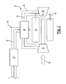
- a gas turbine engine assembly 10 includes a compressor 12 a combustor 14 and a turbine 16. Airflow 26 entering the compressor 12 is compressed to a high pressure and directed towards the combustor 14. In the combustor 14, fuel 22 is mixed with the high-pressure air and ignited. Resulting hot combustion gases 15 are exhausted to drive the turbine 16.
- Hot combustion gases 15 exhausted to drive the turbine 16 are typically at temperatures that can potentially damage metal components of the engine 10.
- An air passage 19 leading from the compressor 12 supplies high-pressure air 18 to the turbine 16.
- High-pressure air 18 creates a boundary layer that insulates metal components from the hot combustion gases 15 flowing over the turbine 16.
- the air 18 within the air passage 19 cooling the turbine 16 must be at a temperature that provides the desired cooling benefits to the turbine 16. The greater the temperature of the air flowing over the turbine 16, the more flow required. More flow from the compressor 12 decreases overall engine efficiencies. For this reason the air 18 within the air passage 19 is first routed through a fuel/air heat exchanger 20. Air 18 within the air passage 19 is placed in thermal contact to reject heat to fuel 22 in the fuel/air heat exchanger 20.
- Usable cooling capacity of the fuel 22 is increased by removing dissolved oxygen.
- the presence of dissolved oxygen within the fuel causes most aircraft fuels to break down at temperatures greater than about 250°F (121 °C).
- the breakdown of fuel results in the formation of insoluble coke deposits on components within fuel passages 23 and the combustor 14.
- the formation of undesirable coke deposits causes degradation of engine efficiencies and/or requires additional maintenance.
- the fuel system includes a fuel deoxygenator 24 for removing dissolved oxygen from the fuel 22.
- a schematic view of a fuel deoxygenator 24' includes a plurality of tubes 34 disposed within a housing 36.
- the fuel 22 is flowed around the tubes 34 from an inlet 38 to an outlet 40.
- Tubes 34 include a composite permeable membrane 30 that absorbs oxygen molecules dissolved within the fuel 22.
- a strip gas 32 flowing through the tubes 34 creates a partial pressure differential across the composite permeable membrane 30 that draws dissolved oxygen from the fuel 22 into the tubes 34 and out with the strip gas 32.
- Oxygen is then removed from the strip gas 32 and exhausted from the system.
- the strip gas 32 is then recycled through the fuel deoxygenator 24'.
- Deoxygenated fuel exits through the outlet 40 and into the fuel/air heat exchanger 20 for absorbing heat from cooling air 18.
- FIG. 3 another embodiment of a fuel deoxygenator 24" is shown and includes a series of fuel plates 42 stacked one on top of the other.
- the composite permeable membrane 30 is included on each of the fuel plates 42 to define a portion of fuel passages 46.
- Fuel enters through an inlet 48 and exists through an outlet 50.
- An opening 49 is open to a vacuum source 56.
- Fuel 22 passes within the fuel passages 46 defined by the stacked fuel plates 42.
- the fuel plates 42 are disposed within the housing 44 that defines the inlet 48 and the outlet 50.
- the use of the fuel plates 42 allows for the adaptation of the fuel deoxygenator 24" to various applications by the addition or subtraction of fuel plates 42.
- the composite permeable membrane 30 is shown in cross-section and preferably includes a permeable layer 52 disposed over a porous backing 51.
- the porous backing 51 supplies the required support structure for the permeable layer 52 while still allowing maximum oxygen diffusion from fuel.
- the permeable layer 52 is coated on to the porous backing 51 and a mechanical bond between the two is formed.
- the permeable layer 52 is preferably a 0.5-20 ⁇ m thick coating of Teflon® AF 2400 over a 0.005-in (0.127mm) thick porous backing 51 of polyvinylidene fluoride (PVDF) with a 0.25 ⁇ m pores size.
- PVDF polyvinylidene fluoride
- Other supports of different material, thickness and pore size can be used that provide the requisite strength and openness.
- the permeable layer 52 is Dupont Teflon® AF amorphous fluoropolymer however other materials known to workers skilled in the art are within the contemplation of this invention, such as Solvay Hyflon AD perfluorinated glassy polymer and Asahi Glass CYTOP polyperfluorobutenyl vinyl ether.
- Each composite permeable membrane 30 is supported on a porous substrate 54.
- the porous substrate 54 is in communication with the vacuum source 56 to create an oxygen partial pressure differential across the composite permeable membrane 30.
- a partial pressure differential is created by the vacuum source 56 between a non-fuel side 55 of the permeable membrane 30 and a fuel side 57.
- Oxygen indicated at arrows 58 diffuses from fuel 22 across the composite permeable membrane 30 and into the porous substrate 54. From the porous substrate 54 the oxygen 58 is pulled and vented out of the fuel system.
- the efficiency of a gas turbine engine is related to the temperatures that the engine can achieve. Higher temperatures enable better fuel burn capabilities that in turn result in longer range for the aircraft. Increased temperatures are enabled by cooled cooling air 18 from the compressor 12 that is routed through the fuel/air heat exchanger 20. As appreciated, air bled from the compressor 12 reduces the efficiency of the engine 10. The reduction of air bled from the compressor 12 facilitated by the increased heat sink capacity of deoxygenated fuel increases overall engine operating efficiency.
Landscapes
- Engineering & Computer Science (AREA)
- Chemical & Material Sciences (AREA)
- Combustion & Propulsion (AREA)
- Mechanical Engineering (AREA)
- General Engineering & Computer Science (AREA)
- Life Sciences & Earth Sciences (AREA)
- Environmental Sciences (AREA)
- Chemical Kinetics & Catalysis (AREA)
- Animal Husbandry (AREA)
- Biodiversity & Conservation Biology (AREA)
- Separation Using Semi-Permeable Membranes (AREA)
- Turbine Rotor Nozzle Sealing (AREA)
Applications Claiming Priority (2)
| Application Number | Priority Date | Filing Date | Title |
|---|---|---|---|
| US10/767,582 US7231769B2 (en) | 2004-01-29 | 2004-01-29 | Gas turbine cooling system |
| US767582 | 2004-01-29 |
Publications (3)
| Publication Number | Publication Date |
|---|---|
| EP1559883A2 true EP1559883A2 (de) | 2005-08-03 |
| EP1559883A3 EP1559883A3 (de) | 2008-12-10 |
| EP1559883B1 EP1559883B1 (de) | 2011-07-27 |
Family
ID=34654352
Family Applications (1)
| Application Number | Title | Priority Date | Filing Date |
|---|---|---|---|
| EP05250352A Expired - Lifetime EP1559883B1 (de) | 2004-01-29 | 2005-01-25 | Gasturbine mit einem Brennstoffentgaser |
Country Status (6)
| Country | Link |
|---|---|
| US (1) | US7231769B2 (de) |
| EP (1) | EP1559883B1 (de) |
| JP (1) | JP2005214202A (de) |
| KR (1) | KR20050077734A (de) |
| CN (1) | CN1648428A (de) |
| CA (1) | CA2492566A1 (de) |
Cited By (4)
| Publication number | Priority date | Publication date | Assignee | Title |
|---|---|---|---|---|
| EP1775514A3 (de) * | 2005-10-11 | 2009-12-09 | United Technologies Corporation | Brennstoffsystem und Verfahren zur Verminderung des Ausstosses |
| EP1795805A3 (de) * | 2005-12-08 | 2010-07-07 | United Technologies Corporation | Fette katalytische rückstandsfreie Verbrennung für flüssigen Brennstoff mit Brennstoffstabilisierungseinheit |
| FR2981123A1 (fr) * | 2011-10-07 | 2013-04-12 | Snecma | Dispositif de refroidissement d'air dans un moteur d'aeronef |
| US9759130B2 (en) | 2012-09-28 | 2017-09-12 | Rolls-Royce Plc | Gas turbine engine with cooling system |
Families Citing this family (33)
| Publication number | Priority date | Publication date | Assignee | Title |
|---|---|---|---|---|
| US7465335B2 (en) * | 2005-02-02 | 2008-12-16 | United Technologies Corporation | Fuel deoxygenation system with textured oxygen permeable membrane |
| US20080016846A1 (en) * | 2006-07-18 | 2008-01-24 | United Technologies Corporation | System and method for cooling hydrocarbon-fueled rocket engines |
| EP1975388A1 (de) * | 2007-03-28 | 2008-10-01 | Siemens Aktiengesellschaft | Gasturbinentriebwerk mit Brennstoffverdichter |
| US20100011781A1 (en) * | 2008-07-21 | 2010-01-21 | Lents Charles E | Heat exchanger assembly for an aircraft control |
| KR20120042713A (ko) | 2009-02-04 | 2012-05-03 | 퍼듀 리서치 파운데이션 | 금속 수소화물 저장 시스템용 코일형 마이크로채널 열교환기 |
| JP2012516984A (ja) | 2009-02-04 | 2012-07-26 | パーデュ リサーチ ファンデーション | 金属水素化物貯蔵システム用の羽根付き熱交換器 |
| WO2010099535A2 (en) * | 2009-02-27 | 2010-09-02 | Purdue Research Foundation | Liquid-gas heat exchanger |
| US20110232298A1 (en) * | 2010-03-23 | 2011-09-29 | General Electric Company | System and method for cooling gas turbine components |
| US8300412B2 (en) | 2010-09-30 | 2012-10-30 | Hamilton Sundstrand Corporation | Heat exchanger for motor controller |
| US8943827B2 (en) | 2011-05-31 | 2015-02-03 | Pratt & Whitney Canada Corp. | Fuel air heat exchanger |
| US9580185B2 (en) | 2012-01-20 | 2017-02-28 | Hamilton Sundstrand Corporation | Small engine cooled cooling air system |
| US9109842B2 (en) | 2012-02-24 | 2015-08-18 | Pratt & Whitney Canada Corp. | Fuel air heat exchanger |
| US9429072B2 (en) | 2013-05-22 | 2016-08-30 | General Electric Company | Return fluid air cooler system for turbine cooling with optional power extraction |
| US9422063B2 (en) | 2013-05-31 | 2016-08-23 | General Electric Company | Cooled cooling air system for a gas turbine |
| US20160237950A1 (en) * | 2013-10-07 | 2016-08-18 | United Technologies Corporation | Backside coating cooling passage |
| WO2015065587A1 (en) | 2013-11-04 | 2015-05-07 | United Technologies Corporation | Coated cooling passage |
| US9789972B2 (en) * | 2014-06-27 | 2017-10-17 | Hamilton Sundstrand Corporation | Fuel and thermal management system |
| US9752507B2 (en) | 2015-02-10 | 2017-09-05 | United Technologies Corporation | Aircraft system with fuel-to-fuel heat exchanger |
| US9932940B2 (en) | 2015-03-30 | 2018-04-03 | Honeywell International Inc. | Gas turbine engine fuel cooled cooling air heat exchanger |
| US20170184026A1 (en) * | 2015-12-28 | 2017-06-29 | General Electric Company | System and method of soakback mitigation through passive cooling |
| US11242800B2 (en) * | 2017-11-07 | 2022-02-08 | General Electric Company | Systems and methods for reducing coke formation of fuel supply systems |
| US11186382B2 (en) * | 2018-11-02 | 2021-11-30 | General Electric Company | Fuel oxygen conversion unit |
| CN109681675B (zh) * | 2019-02-25 | 2020-05-19 | 国电环境保护研究院有限公司 | 一种温控阀阀芯及自动式温控阀 |
| CN111075573A (zh) * | 2019-12-03 | 2020-04-28 | 哈尔滨工程大学 | 一种舰船燃气轮机柴油闪蒸喷雾系统 |
| US11047306B1 (en) * | 2020-02-25 | 2021-06-29 | General Electric Company | Gas turbine engine reverse bleed for coking abatement |
| US12139270B2 (en) | 2021-04-19 | 2024-11-12 | General Electric Company | Aircraft thermal transport system and method |
| US12503980B2 (en) | 2022-11-01 | 2025-12-23 | General Electric Company | Gas turbine engine |
| US12428992B2 (en) | 2022-11-01 | 2025-09-30 | General Electric Company | Gas turbine engine |
| US12196131B2 (en) | 2022-11-01 | 2025-01-14 | General Electric Company | Gas turbine engine |
| US12392290B2 (en) | 2022-11-01 | 2025-08-19 | General Electric Company | Gas turbine engine |
| US12535033B2 (en) | 2022-11-01 | 2026-01-27 | General Electric Company | Gas turbine engine |
| US12410753B2 (en) | 2022-11-01 | 2025-09-09 | General Electric Company | Gas turbine engine |
| US12540551B1 (en) | 2025-07-01 | 2026-02-03 | General Electric Company | Gas turbine engines including splittered airfoils |
Citations (3)
| Publication number | Priority date | Publication date | Assignee | Title |
|---|---|---|---|---|
| EP0584958A1 (de) | 1992-08-03 | 1994-03-02 | General Electric Company | Luftkühlung mit Zwischenkühlung für Turbinenschaufeln |
| US6315815B1 (en) | 1999-12-16 | 2001-11-13 | United Technologies Corporation | Membrane based fuel deoxygenator |
| EP1154135A2 (de) | 2000-05-11 | 2001-11-14 | General Electric Company | Methode und Einrichtung um eine Turbine mit Kühlluft zu versorgen |
Family Cites Families (16)
| Publication number | Priority date | Publication date | Assignee | Title |
|---|---|---|---|---|
| US3751879A (en) * | 1971-04-26 | 1973-08-14 | Instrumentation Specialties Co | Apparatus for reducing the dissolved gas concentration in a liquid |
| GB2234520B (en) * | 1989-07-24 | 1993-04-28 | United Technologies Corp | Fuel thermal stability enhancement by chemical deoxygenation |
| US5504256A (en) * | 1995-03-10 | 1996-04-02 | Exxon Research And Engineering Company | Catalytic production of aryl alkyl hydroperoxides by polynuclear transition metal aggregates (LAW229) |
| US5619855A (en) * | 1995-06-07 | 1997-04-15 | General Electric Company | High inlet mach combustor for gas turbine engine |
| US5888275A (en) * | 1996-02-26 | 1999-03-30 | Japan Gore-Tex, Inc. | Assembly for deaeration of liquids |
| US5876604A (en) * | 1996-10-24 | 1999-03-02 | Compact Membrane Systems, Inc | Method of gasifying or degasifying a liquid |
| JPH1193694A (ja) | 1997-09-18 | 1999-04-06 | Toshiba Corp | ガスタービンプラント |
| US5992920A (en) * | 1998-06-23 | 1999-11-30 | R-Vision | Foldout recreational vehicle |
| DE69828594T2 (de) * | 1998-07-17 | 2005-06-16 | Agilent Technologies Inc., A Delaware Corp., Palo Alto | Vorrichtung zum Entgasen von Flüssigkeiten |
| US6672072B1 (en) * | 1998-08-17 | 2004-01-06 | General Electric Company | Pressure boosted compressor cooling system |
| US6647730B2 (en) * | 2001-10-31 | 2003-11-18 | Pratt & Whitney Canada Corp. | Turbine engine having turbine cooled with diverted compressor intermediate pressure air |
| US6709492B1 (en) * | 2003-04-04 | 2004-03-23 | United Technologies Corporation | Planar membrane deoxygenator |
| US6939392B2 (en) * | 2003-04-04 | 2005-09-06 | United Technologies Corporation | System and method for thermal management |
| US20050137441A1 (en) * | 2003-12-18 | 2005-06-23 | Harry Cordatos | Multi-stage fuel deoxygenator |
| US7093437B2 (en) * | 2004-01-29 | 2006-08-22 | United Technologies Corporation | Extended operability aircraft fuel delivery system |
| US7377112B2 (en) * | 2005-06-22 | 2008-05-27 | United Technologies Corporation | Fuel deoxygenation for improved combustion performance |
-
2004
- 2004-01-29 US US10/767,582 patent/US7231769B2/en not_active Expired - Lifetime
-
2005
- 2005-01-13 CA CA002492566A patent/CA2492566A1/en not_active Abandoned
- 2005-01-14 KR KR1020050003573A patent/KR20050077734A/ko not_active Abandoned
- 2005-01-25 EP EP05250352A patent/EP1559883B1/de not_active Expired - Lifetime
- 2005-01-26 JP JP2005018875A patent/JP2005214202A/ja active Pending
- 2005-01-28 CN CNA2005100063660A patent/CN1648428A/zh active Pending
Patent Citations (3)
| Publication number | Priority date | Publication date | Assignee | Title |
|---|---|---|---|---|
| EP0584958A1 (de) | 1992-08-03 | 1994-03-02 | General Electric Company | Luftkühlung mit Zwischenkühlung für Turbinenschaufeln |
| US6315815B1 (en) | 1999-12-16 | 2001-11-13 | United Technologies Corporation | Membrane based fuel deoxygenator |
| EP1154135A2 (de) | 2000-05-11 | 2001-11-14 | General Electric Company | Methode und Einrichtung um eine Turbine mit Kühlluft zu versorgen |
Cited By (5)
| Publication number | Priority date | Publication date | Assignee | Title |
|---|---|---|---|---|
| EP1775514A3 (de) * | 2005-10-11 | 2009-12-09 | United Technologies Corporation | Brennstoffsystem und Verfahren zur Verminderung des Ausstosses |
| US7867324B2 (en) | 2005-10-11 | 2011-01-11 | United Technologies Corporation | Fuel system and method of reducing emission |
| EP1795805A3 (de) * | 2005-12-08 | 2010-07-07 | United Technologies Corporation | Fette katalytische rückstandsfreie Verbrennung für flüssigen Brennstoff mit Brennstoffstabilisierungseinheit |
| FR2981123A1 (fr) * | 2011-10-07 | 2013-04-12 | Snecma | Dispositif de refroidissement d'air dans un moteur d'aeronef |
| US9759130B2 (en) | 2012-09-28 | 2017-09-12 | Rolls-Royce Plc | Gas turbine engine with cooling system |
Also Published As
| Publication number | Publication date |
|---|---|
| US20050166598A1 (en) | 2005-08-04 |
| KR20050077734A (ko) | 2005-08-03 |
| EP1559883A3 (de) | 2008-12-10 |
| CA2492566A1 (en) | 2005-07-29 |
| US7231769B2 (en) | 2007-06-19 |
| JP2005214202A (ja) | 2005-08-11 |
| EP1559883B1 (de) | 2011-07-27 |
| CN1648428A (zh) | 2005-08-03 |
Similar Documents
| Publication | Publication Date | Title |
|---|---|---|
| US7231769B2 (en) | Gas turbine cooling system | |
| US7445659B2 (en) | Ejector to reduce permeate backpressure of air separation module | |
| EP1677888B1 (de) | System und verfahren für thermomanagement | |
| EP1559884B1 (de) | Brennstoffzufuhrsystem mit Entlüftungsvorrichtung für ein Flugtriebwerk und zugehöriges Verfahren | |
| CN104736817B (zh) | 再循环用于燃气涡轮发动机中多个流动路径中的排气的系统和方法 | |
| KR100656871B1 (ko) | 연료 탈산소화 장치 | |
| US7334407B2 (en) | Method of suppressing coke in endothermic fuel processing | |
| EP2003311B1 (de) | Hybridkühlung eines Gasturbinenmotors | |
| US7824470B2 (en) | Method for enhancing mass transport in fuel deoxygenation systems | |
| CN102939679B (zh) | 具有设置在外壳内的燃料电池的燃料电池系统 | |
| US20060278073A1 (en) | Fuel deoxygenation system with non-planar plate members | |
| JP2016194295A (ja) | タービンエンジンを冷却するためのシステム | |
| FR2503255A1 (fr) | Dispositif de refroidissement pour generateur electrique d'un moteur a turbine a gaz | |
| JP2010180878A (ja) | セラミック・マトリックス複合材料タービン・エンジン | |
| KR101617705B1 (ko) | 복합냉각유체를 이용한 가스터빈 베인 및 블레이드 냉각시스템, 이에 의해 냉각되는 가스터빈 베인 및 블레이드 구조, 및 이를 이용하여 가스터빈 베인 및 블레이드를 냉각하는 냉각방법 | |
| US8794907B1 (en) | Multiple staged compressor with last stage airfoil cooling | |
| US20050137441A1 (en) | Multi-stage fuel deoxygenator | |
| JP2010031866A (ja) | ターボ機械用のヒートパイプ中間冷却器 | |
| EP1782879A1 (de) | System zum Entfernen von Sauerstoff aus Treibstoff mittels einer mehrschichtigen sauerstoffpermeablen Membran | |
| CN120604025A (zh) | 燃气涡轮机组通风系统和用于对燃气涡轮机组进行通风的方法 | |
| US12326092B2 (en) | Engine exhaust reverse flow prevention | |
| CN119531970A (zh) | 带盒形隔热罩结构的涡轮级间机匣及航空发动机 | |
| FR3133404A1 (fr) | Système de suralimentation en air pour système de conditionnement de carburant et procédé d’utilisation | |
| JP2019110095A (ja) | 燃料電池システム |
Legal Events
| Date | Code | Title | Description |
|---|---|---|---|
| PUAI | Public reference made under article 153(3) epc to a published international application that has entered the european phase |
Free format text: ORIGINAL CODE: 0009012 |
|
| AK | Designated contracting states |
Kind code of ref document: A2 Designated state(s): AT BE BG CH CY CZ DE DK EE ES FI FR GB GR HU IE IS IT LI LT LU MC NL PL PT RO SE SI SK TR |
|
| AX | Request for extension of the european patent |
Extension state: AL BA HR LV MK YU |
|
| PUAL | Search report despatched |
Free format text: ORIGINAL CODE: 0009013 |
|
| AK | Designated contracting states |
Kind code of ref document: A3 Designated state(s): AT BE BG CH CY CZ DE DK EE ES FI FR GB GR HU IE IS IT LI LT LU MC NL PL PT RO SE SI SK TR |
|
| AX | Request for extension of the european patent |
Extension state: AL BA HR LV MK YU |
|
| 17P | Request for examination filed |
Effective date: 20090210 |
|
| 17Q | First examination report despatched |
Effective date: 20090406 |
|
| AKX | Designation fees paid |
Designated state(s): DE GB |
|
| RTI1 | Title (correction) |
Free format text: GAS TURBINE ENGINE COMPRISING A FUEL DEOXYGENATOR |
|
| GRAP | Despatch of communication of intention to grant a patent |
Free format text: ORIGINAL CODE: EPIDOSNIGR1 |
|
| GRAS | Grant fee paid |
Free format text: ORIGINAL CODE: EPIDOSNIGR3 |
|
| GRAA | (expected) grant |
Free format text: ORIGINAL CODE: 0009210 |
|
| AK | Designated contracting states |
Kind code of ref document: B1 Designated state(s): DE GB |
|
| REG | Reference to a national code |
Ref country code: GB Ref legal event code: FG4D |
|
| REG | Reference to a national code |
Ref country code: DE Ref legal event code: R081 Ref document number: 602005029166 Country of ref document: DE Owner name: UNITED TECHNOLOGIES CORP. (N.D.GES.D. STAATES , US Free format text: FORMER OWNER: UNITED TECHNOLOGIES CORP. (N.D.GES.D. STAATES DELAWARE), HARTFORD, CONN., US |
|
| REG | Reference to a national code |
Ref country code: DE Ref legal event code: R096 Ref document number: 602005029166 Country of ref document: DE Effective date: 20110922 |
|
| PLBE | No opposition filed within time limit |
Free format text: ORIGINAL CODE: 0009261 |
|
| STAA | Information on the status of an ep patent application or granted ep patent |
Free format text: STATUS: NO OPPOSITION FILED WITHIN TIME LIMIT |
|
| 26N | No opposition filed |
Effective date: 20120502 |
|
| REG | Reference to a national code |
Ref country code: DE Ref legal event code: R097 Ref document number: 602005029166 Country of ref document: DE Effective date: 20120502 |
|
| REG | Reference to a national code |
Ref country code: DE Ref legal event code: R082 Ref document number: 602005029166 Country of ref document: DE Representative=s name: SCHMITT-NILSON SCHRAUD WAIBEL WOHLFROM PATENTA, DE |
|
| REG | Reference to a national code |
Ref country code: DE Ref legal event code: R082 Ref document number: 602005029166 Country of ref document: DE Representative=s name: SCHMITT-NILSON SCHRAUD WAIBEL WOHLFROM PATENTA, DE Ref country code: DE Ref legal event code: R081 Ref document number: 602005029166 Country of ref document: DE Owner name: UNITED TECHNOLOGIES CORP. (N.D.GES.D. STAATES , US Free format text: FORMER OWNER: UNITED TECHNOLOGIES CORPORATION, HARTFORD, CONN., US |
|
| REG | Reference to a national code |
Ref country code: DE Ref legal event code: R081 Ref document number: 602005029166 Country of ref document: DE Owner name: RAYTHEON TECHNOLOGIES CORPORATION (N.D.GES.D.S, US Free format text: FORMER OWNER: UNITED TECHNOLOGIES CORP. (N.D.GES.D. STAATES DELAWARE), FARMINGTON, CONN., US |
|
| P01 | Opt-out of the competence of the unified patent court (upc) registered |
Effective date: 20230519 |
|
| PGFP | Annual fee paid to national office [announced via postgrant information from national office to epo] |
Ref country code: GB Payment date: 20231219 Year of fee payment: 20 |
|
| PGFP | Annual fee paid to national office [announced via postgrant information from national office to epo] |
Ref country code: DE Payment date: 20231219 Year of fee payment: 20 |
|
| REG | Reference to a national code |
Ref country code: DE Ref legal event code: R071 Ref document number: 602005029166 Country of ref document: DE |
|
| REG | Reference to a national code |
Ref country code: GB Ref legal event code: PE20 Expiry date: 20250124 |
|
| PG25 | Lapsed in a contracting state [announced via postgrant information from national office to epo] |
Ref country code: GB Free format text: LAPSE BECAUSE OF EXPIRATION OF PROTECTION Effective date: 20250124 |