EP1154135A2 - Methode und Einrichtung um eine Turbine mit Kühlluft zu versorgen - Google Patents
Methode und Einrichtung um eine Turbine mit Kühlluft zu versorgen Download PDFInfo
- Publication number
- EP1154135A2 EP1154135A2 EP01301950A EP01301950A EP1154135A2 EP 1154135 A2 EP1154135 A2 EP 1154135A2 EP 01301950 A EP01301950 A EP 01301950A EP 01301950 A EP01301950 A EP 01301950A EP 1154135 A2 EP1154135 A2 EP 1154135A2
- Authority
- EP
- European Patent Office
- Prior art keywords
- heat exchanger
- gas turbine
- air
- turbine engine
- heat
- Prior art date
- Legal status (The legal status is an assumption and is not a legal conclusion. Google has not performed a legal analysis and makes no representation as to the accuracy of the status listed.)
- Granted
Links
Images


Classifications
-
- F—MECHANICAL ENGINEERING; LIGHTING; HEATING; WEAPONS; BLASTING
- F02—COMBUSTION ENGINES; HOT-GAS OR COMBUSTION-PRODUCT ENGINE PLANTS
- F02C—GAS-TURBINE PLANTS; AIR INTAKES FOR JET-PROPULSION PLANTS; CONTROLLING FUEL SUPPLY IN AIR-BREATHING JET-PROPULSION PLANTS
- F02C7/00—Features, components parts, details or accessories, not provided for in, or of interest apart form groups F02C1/00 - F02C6/00; Air intakes for jet-propulsion plants
- F02C7/22—Fuel supply systems
- F02C7/224—Heating fuel before feeding to the burner
-
- F—MECHANICAL ENGINEERING; LIGHTING; HEATING; WEAPONS; BLASTING
- F02—COMBUSTION ENGINES; HOT-GAS OR COMBUSTION-PRODUCT ENGINE PLANTS
- F02C—GAS-TURBINE PLANTS; AIR INTAKES FOR JET-PROPULSION PLANTS; CONTROLLING FUEL SUPPLY IN AIR-BREATHING JET-PROPULSION PLANTS
- F02C7/00—Features, components parts, details or accessories, not provided for in, or of interest apart form groups F02C1/00 - F02C6/00; Air intakes for jet-propulsion plants
- F02C7/12—Cooling of plants
- F02C7/14—Cooling of plants of fluids in the plant, e.g. lubricant or fuel
-
- F—MECHANICAL ENGINEERING; LIGHTING; HEATING; WEAPONS; BLASTING
- F02—COMBUSTION ENGINES; HOT-GAS OR COMBUSTION-PRODUCT ENGINE PLANTS
- F02C—GAS-TURBINE PLANTS; AIR INTAKES FOR JET-PROPULSION PLANTS; CONTROLLING FUEL SUPPLY IN AIR-BREATHING JET-PROPULSION PLANTS
- F02C7/00—Features, components parts, details or accessories, not provided for in, or of interest apart form groups F02C1/00 - F02C6/00; Air intakes for jet-propulsion plants
- F02C7/12—Cooling of plants
- F02C7/16—Cooling of plants characterised by cooling medium
- F02C7/18—Cooling of plants characterised by cooling medium the medium being gaseous, e.g. air
-
- F—MECHANICAL ENGINEERING; LIGHTING; HEATING; WEAPONS; BLASTING
- F28—HEAT EXCHANGE IN GENERAL
- F28D—HEAT-EXCHANGE APPARATUS, NOT PROVIDED FOR IN ANOTHER SUBCLASS, IN WHICH THE HEAT-EXCHANGE MEDIA DO NOT COME INTO DIRECT CONTACT
- F28D7/00—Heat-exchange apparatus having stationary tubular conduit assemblies for both heat-exchange media, the media being in contact with different sides of a conduit wall
- F28D7/06—Heat-exchange apparatus having stationary tubular conduit assemblies for both heat-exchange media, the media being in contact with different sides of a conduit wall the conduits having a single U-bend
-
- F—MECHANICAL ENGINEERING; LIGHTING; HEATING; WEAPONS; BLASTING
- F04—POSITIVE - DISPLACEMENT MACHINES FOR LIQUIDS; PUMPS FOR LIQUIDS OR ELASTIC FLUIDS
- F04D—NON-POSITIVE-DISPLACEMENT PUMPS
- F04D29/00—Details, component parts, or accessories
- F04D29/40—Casings; Connections of working fluid
- F04D29/52—Casings; Connections of working fluid for axial pumps
- F04D29/54—Fluid-guiding means, e.g. diffusers
- F04D29/541—Specially adapted for elastic fluid pumps
- F04D29/545—Ducts
-
- Y—GENERAL TAGGING OF NEW TECHNOLOGICAL DEVELOPMENTS; GENERAL TAGGING OF CROSS-SECTIONAL TECHNOLOGIES SPANNING OVER SEVERAL SECTIONS OF THE IPC; TECHNICAL SUBJECTS COVERED BY FORMER USPC CROSS-REFERENCE ART COLLECTIONS [XRACs] AND DIGESTS
- Y02—TECHNOLOGIES OR APPLICATIONS FOR MITIGATION OR ADAPTATION AGAINST CLIMATE CHANGE
- Y02T—CLIMATE CHANGE MITIGATION TECHNOLOGIES RELATED TO TRANSPORTATION
- Y02T50/00—Aeronautics or air transport
- Y02T50/60—Efficient propulsion technologies, e.g. for aircraft
Definitions
- This invention relates generally to turbine engines, and more particularly, to cooling systems for turbine engines.
- a gas turbine engine typically includes a multi-stage axial compressor, a combustor, and a turbine. Airflow entering the compressor is compressed and directed to the combustor where it is mixed with fuel and ignited, producing hot combustion gases used to drive the turbine. As a result of the hot combustion gases entering the turbine, typically compressor air is channeled through a turbine cooling circuit and used to cool the turbine.
- Compressor bleed air is often used as a source of cooling air for the turbine cooling circuit.
- extracting cooling air from the compressor may affect overall gas turbine engine performance.
- the cooling system may use fuel flowing through a heat exchanger to absorb heat from the compressor bleed air. As the fuel absorbs heat from the compressor bleed air, the temperature of the bleed air is lowered and engine cooling airflow requirements are reduced, thus reducing engine performance losses.
- a cooling system reduces fuel gum deposits within the cooling system and provides cooling air to the gas turbine engine.
- the cooling system includes a recirculating loop including a plurality of heat exchangers in fluid communication with the recirculating loop.
- a first heat exchanger is an air-steam heat exchanger that uses heat transfer fluid to cool cooling air used by the gas turbine engine.
- a second heat exchanger is an air-steam heat exchanger that uses engine fan air to cool the heat transfer fluid circulating in the recirculating loop.
- a third of the heat exchangers is a steam-fuel heat exchanger that uses combustor main fuel flow as a heat sink to cool the heat transfer fluid circulating in the recirculating loop.
- the cooling system is selectively operable to reduce fuel gum deposits and provide cooling air to the gas turbine engine when the gas turbine engine is operating.
- a flow of heat transfer fluid through the third heat exchanger is modulated by a bypass line and valve to control the heat transfer from the heat transfer fluid to the fuel flow to reduce fuel gum deposits.
- the cooling system may be operated using either fuel flow or fan discharge airflow as a heat sink with all three heat exchangers in operation.
- the cooling system may be operated using fan discharge airflow as a heat sink with the third heat exchanger bypassed.
- Fuel is used as a heat sink when sufficient deposit dissipation forces are prevalent within the third heat exchanger or when a maximum temperature of the fuel can be controlled such that the temperature remains below temperatures conducive to fuel gum deposit formation.
- Fuel passing through the third heat exchanger flows through a path that increases heat transfer from the heat transfer fluid to the fuel. As a result of the flow through the fuel paths, the fuel flow develops high fluid turbulent forces and fluid shear forces that reduce fuel deposits within the third heat exchanger.
- Figure 1 is a schematic illustration of a gas turbine engine 10 including a low pressure compressor 12, a high pressure compressor 14, and a combustor 16.
- Engine 10 also includes a high pressure turbine 18 and a low pressure turbine 20.
- compressor 12 and turbine 20 are coupled by a first shaft 21, and compressor 14 and turbine 18 are coupled by a second shaft 22.
- gas turbine engine 10 is an F110 engine commercially available from General Electric Aircraft Engines, Cincinnati, Ohio.
- the highly compressed air is delivered to combustor 16.
- Airflow from combustor 16 drives turbines 18 and 20 and exits gas turbine engine 10 through a nozzle 24.
- FIG. 2 is a schematic illustration of a cooling system 40 used with gas turbine engine 10.
- Cooling system 40 is an indirect cooling system (ICS) that is selectively operable.
- Compressor bleed air 42 is extracted by cooling system 40 from high pressure compressor 14 from intermediate stages 41 of compressor 14.
- compressor bleed air 42 is extracted by cooling system 40 from a high pressure compressor discharge (not shown) of compressor 14.
- System 40 uses fan discharge air 43 and combustor fuel flow 44 as heat sinks to provide heated fuel flow to combustor 16 and cooled interstage compressor bleed air 42 to cool low pressure turbine 20 and associated turbine components (not shown).
- cooling system 40 supplies compressor discharge bleed air 42 to cool high pressure turbine 18 and associated turbine components (not shown).
- Recirculating loop 46 is a closed loop and includes a first heat exchanger 50, a second heat exchanger 52, and a third heat exchanger 54. Because recirculating loop 46 is a closed loop, no make-up water is used.
- First heat exchanger 50 is an air-steam heat exchanger and transfers heat from compressor bleed air 42 to a suitable heat transfer fluid circulated in recirculating loop 46.
- the heat transfer fluid is a water and methanol mix wherein the water is pure de-ionized laboratory grade water and the methanol prevents the heat transfer fluid from freezing when gas turbine engine 10 is inoperative and when the heat transfer fluid is not circulating. Buffer compounds are added to recirculating loop 46 to adjust the water chemistry and prevent corrosion within recirculating loop 46.
- recirculating loop 46 is coated with a metal oxide chemical vapor deposition coating to prevent corrosion.
- Steam exiting first heat exchanger 50 is routed directly to second heat exchanger 52.
- steam refers to the vapor phase of a two phase liquid-vapor system that occurs when a temperature exceeds a saturation temperature for the system pressure, a single phase supercritical fluid where fluid pressure exceeds a critical pressure for the heat transfer fluid and no phase change exists, or a liquid below a saturation temperature at a specified pressure in all or part of recirculating loop 46.
- Second heat exchanger 52 is an air-steam heat exchanger that transfers heat from the heat transfer fluid to gas turbine engine fan discharge air 43.
- Gas turbine engine fan discharge air 43 flows through second heat exchanger 52 and extracts heat from the heat transfer fluid generated as a result of the heat transfer fluid extracting heat from compressor bleed air 42 in first heat exchanger 50. Because second heat exchanger 52 transfers heat from heat transfer fluid to fan discharge air 43, a potential amount of heat that may be transferred to main combustor fuel flow 44 from the heat transfer fluid circulating is reduced. Furthermore, because the formation of fuel deposits is more prevalent at higher temperatures, reducing the temperature of the heat transfer fluid within third heat exchanger 54 also reduces the formation of fuel deposits.
- Third heat exchanger 54 is a steam-fuel heat exchanger that transfers heat from the heat transfer fluid to main combustor fuel flow 44 supplied to combustor 16.
- Main combustor fuel flow 44 is the heat sink used within third heat exchanger 54 that extracts remaining heat added to the heat transfer fluid, i.e. from first heat exchanger 50, that was not transferred to fan discharge air 43 by second heat exchanger 52.
- third heat exchanger 54 establishes an overall heat balance within recirculating loop 46.
- Third heat exchanger 54 includes a first passageway (not shown) and a second passageway (not shown).
- the first passageway includes a plurality of tubes (not shown) that permit heat transfer fluid to flow from second heat exchanger 52 through third heat exchanger 54.
- the second passageway permits main combustor fuel flow 44 to flow through third heat exchanger 54 and around the first passageway plurality of fluid tubes transporting heat transfer fluid.
- a control valve 58 is used to vary an amount of fuel flow 44 entering the third heat exchanger second passageway. A total amount of fuel flow passing through third heat exchanger 54 and control valve 58 equals a total fuel flow 44 supplied to combustor 16.
- the first passage plurality of tubes are closely-spaced and define a plurality of fuel passes extending through the second passageway.
- main combustor fuel flow 44 flows around the tubes through the fuel passages, the closely-spaced passageways cause fluid turbulent forces and fluid shear forces to develop.
- a Reynolds number for the heat transfer fluid increases.
- the increased Reynolds number and the fluid turbulent and shear forces permit the fluid to mitigate any deposit fragments formed on outside surfaces (not shown) of the tubes and separate the deposits from the tubes.
- the loosened deposits are mixed with main combustor fuel flow 44 and burned in combustor 16. Accordingly, deposit agglomeration and blockage within the tubes is reduced.
- Recirculating loop 46 also includes an accumulator 60 and a pump 62.
- accumulator 60 may be a gaseous-nitrogen charged accumulator that maintains system pressure of recirculating loop 46.
- recirculating loop 46 includes a mechanical device (not shown), such as a spring, within accumulator 60 in lieu of gaseous-nitrogen to maintain system pressure of recirculating loop 46.
- Accumulator 60 derives thermal energy from recirculating loop 46 as described in more detail below.
- Pump 62 is a variable-speed recirculation pump that may adjust system pressure within recirculating loop 46. Pump 62 is coupled to a motor 64.
- motor 64 is an electric motor.
- motor 64 and pump 62 are driven by fuel flow 44 in lieu of electric motor 64 and pump 62, and fuel flow pressure is provided by a main fuel pump 66 disposed within gas turbine engine 10.
- Cooling system 40 is coupled to a cooling system electronic control (not shown) that is electrically coupled to an engine control system (not shown).
- the engine control system is known as a full authority digital electronic control (FADEC) available from Lockheed Martin Control Systems, Johnson City, New York.
- the cooling system electronic control regulates energization of pump 62 and also regulates operation of a bypass valve 67 that controls a flow of heat transfer fluid flow through a bypass 68, as well as control valve 58 which controls a bypass of fuel flow 44 around third heat exchanger 54.
- Bypass 68 permits a portion or all of heat transfer fluid flowing in recirculating loop 46 to bypass third heat exchanger 54 when desirable to limit fuel exit temperatures exiting third heat exchanger 54.
- the cooling system electronic control regulates the pressure and cooling capacity of recirculating loop 46 with bypass 68.
- second heat exchanger 52 still provides significant heat transfer for the heat transfer fluid.
- Gas turbine engine 10 includes an engine core casing 70 having an external surface 72 and a fan bypass casing 74 having an internal surface 76 and an external surface 78.
- Engine core casing 70 extends circumferentially around gas turbine engine 10 and extends from compressor 14, combustor 16, and turbines 18 and 20.
- Fan bypass casing 74 extends circumferentially around engine core casing 70 and defines a cavity 80 between core casing 70 and fan bypass casing 74.
- Engine fan discharge flow 43 is directed through cavity 80 to exhaust nozzle 24.
- First heat exchanger 50 is mounted to engine core casing external surface 72 and extends into cavity 80 to attach to a plurality of cooling air tubes 82 disposed within cavity 80. Accordingly, first heat exchanger 50 does not include any air ducts for routing air to first heat exchanger.
- Second heat exchanger 52 is mounted to fan bypass casing internal surface 76 and extends across cavity 80 to enable engine fan discharge flow 43 to pass through second heat exchanger 52.
- Third heat exchanger 54 is mounted to fan bypass casing external surface 78.
- third heat exchanger 54 is optimized for a high deposit dissipation rate and second heat exchanger 52 is optimized for low cooling air pressure drop while providing significant heat sink capacity to system 40 when third heat exchanger 54 is not in operation.
- third heat exchanger 54 is optimized to develop increased fuel Reynolds numbers to increase fuel shear stresses for main combustor fuel flow 44. During engine high fuel flow operations, the fuel shear stresses mitigate gum deposits attached to the outside of the third heat exchanger tubes.
- cooling system 40 may be operated using second heat exchanger 52 and fan discharge airflow 43 as the heat sink.
- heat transfer fluid within recirculating loop 46 is circulated and bypassed around third heat exchanger 54 using bypass valve 67 and bypass 68 to prevent fuel gum deposit formation within third heat exchanger 54.
- bypass 68 can be modulated using bypass valve 67 to prevent an exit temperature of fuel flow 44 from increasing to a temperature conducive to fuel gum deposit formation, while still providing heat sink capacity.
- the operation of heat exchangers 52 and 54 may be varied to optimize the cooling of compressor bleed air 42 while preventing the formation of fuel gum deposits in third heat exchanger 54.
- Initially accumulator 60 is charged to a relatively low pressure. In one embodiment, accumulator 60 is initially charged to approximately 275 psia.
- heat transfer fluid within first heat exchanger 50 initially boils. As the heat transfer fluid boils, accumulator 60 increases in pressure. Accumulator 60 uses additional changes in heat transfer fluid density to pressurize and is thus, self-pressurizing. Eventually, recirculating loop pressures exceed supercritical pressures for the heat transfer fluid, thus maintaining single phase fluid in recirculating loop 46 during steady-state operations.
- pump 62 maintains recirculating loop pressure and fluid flow.
- heat transfer fluid circulating in recirculating loop 46 is circulated at a regulated pressure.
- the regulated flow of heat transfer fluid ensures adequate heat transfer occurs within first, second, and third heat exchangers 50, 52, and 54, respectively.
- the combination of the regulated heat transfer fluid flow, the use of fluid bypass 68 to control exit fuel temperatures, and the fluid forces generated within third heat exchanger 54 during high fuel flow operations reduces fuel gum deposits within third heat exchanger 54 when gas turbine engine 10 is operating over a wide range of operating power levels.
- third heat exchanger 54 Furthermore, as a result of fluid turbulent forces and fluid shear forces developed at high fuel flow rates, deposit fragments formed on outside surfaces (not shown) of the tubes in third heat exchanger 54 are easily separated from the tube surfaces and mixed with main combustor fuel flow 44.
- a fuel filter (not shown) disposed downstream from third heat exchanger 54 may be used to filter such deposits to prevent such deposits from entering fuel nozzles (not shown).
- cooling system 40 When engine 10 returns to low power operations after an extended period of high power operations, cooling system 40 remains in operation and the heat transfer fluid is bypassed through bypass 68 around third heat exchanger 54. Compressor bleed air 42 is then cooled with fan discharge air 43 passing through second heat exchanger 52. Main combustor fuel flow 44 continues to flow through and cool third heat exchanger 54. Accordingly, hot soak-back problems are minimized.
- the pressure of recirculating loop 46 is regulated such that if a leak of the heat transfer fluid occurs within recirculating loop 46 of cooling system 40, only a limited amount of heat transfer fluid escapes before the system pressure drops to a level where leakage can no longer occur.
- the engine control senses a loss in recirculating loop pressure, the engine control may provide a throttle limit to enable engine 10 to operate in a power regime where pre-cooling of turbine cooling air is not required.
- fire hazards associated with recirculating loop 46 are reduced because the mixture of methanol and water is not combustible under ordinary engine operating conditions and because third heat exchanger 54 is mounted externally to engine casing 74. As a result, if a fuel leak develops, fuel is not introduced into engine 10, but rather remains external to engine 10.
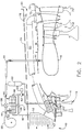
- Figure 3 is a side cross-sectional view of first heat exchanger 50 mounted to engine 10.
- Figure 4 is a partial cross-sectional view of first heat exchanger 50 taken along line 4-4 shown in Figure 3.
- Engine core casing 70 is fabricated from a first portion 90 and a substantially similar second portion (not shown) joined together with a splitline flange (not shown) such that core casing 70 extends circumferentially.
- First heat exchanger 50 is mounted to engine core casing external surface 72 and includes a first portion 94 and an identical second portion (not shown). The heat exchanger second portion and first portion are constructed identically and when connected together, first heat exchanger 50 extends circumferentially around engine core casing 70.
- First heat exchanger 50 includes an outer heat exchanger cover 96 disposed circumferentially around engine core casing 70. Outer heat exchanger cover 96 is attached to engine core casing 70 with a plurality of fasteners 100. A seal (not shown) is disposed between outer heat exchanger cover 96 and core casing external surface 72 and minimizes leakage of cooling air 42 flowing through first heat exchanger 50.
- First heat exchanger 50 is in flow communication with a plurality of first openings 102 and a plurality of second openings 104.
- First openings 102 are disposed circumferentially around engine core casing 70 to permit bleed air 42 to enter first heat exchanger 50.
- Second openings 104 are disposed circumferentially around outer heat exchanger cover 96 to permit bleed air 42 to exit first heat exchanger 50 and enter cooling air tubes 82 and be directed to turbine 20 (shown in Figures 1 and 2).
- First heat exchanger 50 also includes a first manifold 110 disposed at one splitline and a second manifold 112 disposed at the same splitline.
- a plurality of tubing 114 extends between first manifold 110 and second manifold 112 in a two-pass crossflow pattern (not shown).
- heat transfer fluid enters first heat exchanger 50 through first manifold 110, passes through tubing 114, and exits first heat exchanger 50 through second manifold 112.
- the above-described cooling system is cost-effective and highly reliable.
- the cooling system is selectively operable when the gas turbine engine is operating to reduce fuel gum deposits within the cooling system and provide cooling air to the gas turbine engine.
- combustor main fuel flow is used as a heat sink, the cooling system prevents deleterious high temperature fuel deposits from forming within the heat exchanger.
Landscapes
- Engineering & Computer Science (AREA)
- Chemical & Material Sciences (AREA)
- Combustion & Propulsion (AREA)
- Mechanical Engineering (AREA)
- General Engineering & Computer Science (AREA)
- Physics & Mathematics (AREA)
- Thermal Sciences (AREA)
- Turbine Rotor Nozzle Sealing (AREA)
- Engine Equipment That Uses Special Cycles (AREA)
Applications Claiming Priority (2)
| Application Number | Priority Date | Filing Date | Title |
|---|---|---|---|
| US09/567,240 US6584778B1 (en) | 2000-05-11 | 2000-05-11 | Methods and apparatus for supplying cooling air to turbine engines |
| US567240 | 2000-05-11 |
Publications (3)
| Publication Number | Publication Date |
|---|---|
| EP1154135A2 true EP1154135A2 (de) | 2001-11-14 |
| EP1154135A3 EP1154135A3 (de) | 2003-06-04 |
| EP1154135B1 EP1154135B1 (de) | 2006-04-26 |
Family
ID=24266320
Family Applications (1)
| Application Number | Title | Priority Date | Filing Date |
|---|---|---|---|
| EP01301950A Expired - Lifetime EP1154135B1 (de) | 2000-05-11 | 2001-03-05 | Methode und Einrichtung um eine Turbine mit Kühlluft zu versorgen |
Country Status (4)
| Country | Link |
|---|---|
| US (1) | US6584778B1 (de) |
| EP (1) | EP1154135B1 (de) |
| JP (1) | JP4627907B2 (de) |
| DE (1) | DE60119023T2 (de) |
Cited By (14)
| Publication number | Priority date | Publication date | Assignee | Title |
|---|---|---|---|---|
| EP1154136A2 (de) * | 2000-05-11 | 2001-11-14 | General Electric Company | Methode und Einrichtung um die Kühlluft für Gasturbinen zu kühlen |
| WO2005055688A1 (en) * | 2003-11-28 | 2005-06-16 | Rolls Royce Plc | Control arrangement |
| EP1559883A2 (de) | 2004-01-29 | 2005-08-03 | United Technologies Corporation | Kühlsystem für Gasturbinen |
| WO2006056163A1 (de) * | 2004-11-24 | 2006-06-01 | Mtu Aero Engines Gmbh | Vorrichtung zur entnahme und rückführung von kühlströmen |
| EP2000648A3 (de) * | 2007-06-07 | 2010-12-01 | United Technologies Corporation | Kühlvorrichtung für ein Gasturbinentriebwerk und entsprechendes Gasturbinentriebwerk |
| WO2011156130A1 (en) * | 2010-06-08 | 2011-12-15 | Siemens Energy, Inc. | Cooling system for controlling cooling of rotor cooling air and heating of fuel gas |
| FR2981123A1 (fr) * | 2011-10-07 | 2013-04-12 | Snecma | Dispositif de refroidissement d'air dans un moteur d'aeronef |
| US8636836B2 (en) | 2009-02-04 | 2014-01-28 | Purdue Research Foundation | Finned heat exchangers for metal hydride storage systems |
| US8778063B2 (en) | 2009-02-04 | 2014-07-15 | Purdue Research Foundation | Coiled and microchannel heat exchangers for metal hydride storage systems |
| EP2910887A1 (de) * | 2014-02-21 | 2015-08-26 | Rolls-Royce Corporation | Mikrokanalwärmetauscher für gasturbinenzwischenkühlung und -kondensation |
| EP3054126A1 (de) * | 2015-02-09 | 2016-08-10 | United Technologies Corporation | Wärmetauscher für wärmeverwaltungssysteme |
| US9759130B2 (en) | 2012-09-28 | 2017-09-12 | Rolls-Royce Plc | Gas turbine engine with cooling system |
| EP2522813A3 (de) * | 2011-05-10 | 2018-03-07 | Rolls-Royce plc | Steuergerät zur Verwendung in einem Kraftwerk mit Flüssigkeitskühlsystem und Luftkühlsystem |
| US11788470B2 (en) | 2021-03-01 | 2023-10-17 | General Electric Company | Gas turbine engine thermal management |
Families Citing this family (54)
| Publication number | Priority date | Publication date | Assignee | Title |
|---|---|---|---|---|
| WO2003008792A1 (en) * | 2001-07-18 | 2003-01-30 | Jae-Chang Lee | Jet engine using exhaust gas |
| GB2389174B (en) * | 2002-05-01 | 2005-10-26 | Rolls Royce Plc | Cooling systems |
| US6968696B2 (en) * | 2003-09-04 | 2005-11-29 | Siemens Westinghouse Power Corporation | Part load blade tip clearance control |
| US6935831B2 (en) * | 2003-10-31 | 2005-08-30 | General Electric Company | Methods and apparatus for operating gas turbine engines |
| US7033135B2 (en) * | 2003-11-10 | 2006-04-25 | General Electric Company | Method and apparatus for distributing fluid into a turbomachine |
| US7272933B2 (en) * | 2004-01-28 | 2007-09-25 | General Electric Company | Methods and apparatus for operating gas turbine engines |
| US7744827B2 (en) | 2004-02-13 | 2010-06-29 | United Technologies Corporation | Catalytic treatment of fuel to impart coking resistance |
| GB2413366B (en) * | 2004-04-24 | 2006-09-13 | Rolls Royce Plc | Engine. |
| US7269955B2 (en) * | 2004-08-25 | 2007-09-18 | General Electric Company | Methods and apparatus for maintaining rotor assembly tip clearances |
| US7963100B2 (en) * | 2005-05-25 | 2011-06-21 | Alliant Techsystems Inc. | Cooling system for high-speed vehicles and method of cooling high-speed vehicles |
| US7607307B2 (en) * | 2006-01-06 | 2009-10-27 | General Electric Company | Methods and apparatus for controlling cooling air temperature in gas turbine engines |
| US8776952B2 (en) * | 2006-05-11 | 2014-07-15 | United Technologies Corporation | Thermal management system for turbofan engines |
| US7640751B2 (en) * | 2006-05-25 | 2010-01-05 | Siemens Energy, Inc. | Fuel heating system for turbine engines |
| US7874139B2 (en) * | 2006-10-13 | 2011-01-25 | Siemens Energy, Inc. | IGCC design and operation for maximum plant output and minimum heat rate |
| US8763363B2 (en) * | 2007-07-06 | 2014-07-01 | General Electric Company | Method and system for cooling fluid in a turbine engine |
| US9212623B2 (en) * | 2007-12-26 | 2015-12-15 | United Technologies Corporation | Heat exchanger arrangement for turbine engine |
| DE102008007278B4 (de) * | 2008-02-01 | 2010-04-08 | Airbus Deutschland Gmbh | Bleedairduct-Segment, Bleedairduct-Anordnung mit solchen Bleedairduct-Segmenten und Bleedairduct-System mit Regulierungsvorrichtung |
| US7827795B2 (en) * | 2008-09-19 | 2010-11-09 | Woodward Governor Company | Active thermal protection for fuel injectors |
| US8157503B2 (en) * | 2008-09-22 | 2012-04-17 | Rolls Royce Corporation | Thermal management system |
| US20100319359A1 (en) * | 2009-06-19 | 2010-12-23 | General Electric Company | System and method for heating turbine fuel in a simple cycle plant |
| US8307662B2 (en) * | 2009-10-15 | 2012-11-13 | General Electric Company | Gas turbine engine temperature modulated cooling flow |
| GB2478934B (en) * | 2010-03-24 | 2012-06-13 | Rolls Royce Plc | Fuel heat management system |
| GB201015029D0 (en) * | 2010-09-10 | 2010-10-20 | Rolls Royce Plc | Gas turbine engine |
| DE102010063071A1 (de) * | 2010-12-14 | 2012-06-14 | Rolls-Royce Deutschland Ltd & Co Kg | Kühlvorrichtung für ein Strahltriebwerk |
| US8943827B2 (en) | 2011-05-31 | 2015-02-03 | Pratt & Whitney Canada Corp. | Fuel air heat exchanger |
| GB201121428D0 (en) * | 2011-12-14 | 2012-01-25 | Rolls Royce Plc | Controller |
| US9267434B2 (en) | 2012-01-29 | 2016-02-23 | United Technologies Corporation | Heat exchanger |
| US9109842B2 (en) | 2012-02-24 | 2015-08-18 | Pratt & Whitney Canada Corp. | Fuel air heat exchanger |
| US9714611B2 (en) * | 2013-02-15 | 2017-07-25 | Siemens Energy, Inc. | Heat shield manifold system for a midframe case of a gas turbine engine |
| US9587561B2 (en) | 2013-03-15 | 2017-03-07 | Rolls-Royce North American Technologies, Inc. | Heat exchanger integrated with a gas turbine engine and adaptive flow control |
| US9429072B2 (en) | 2013-05-22 | 2016-08-30 | General Electric Company | Return fluid air cooler system for turbine cooling with optional power extraction |
| US9422063B2 (en) | 2013-05-31 | 2016-08-23 | General Electric Company | Cooled cooling air system for a gas turbine |
| EP3022421B1 (de) | 2013-07-17 | 2020-03-04 | United Technologies Corporation | Gasturbine mit kühlluftführung |
| US9963994B2 (en) * | 2014-04-08 | 2018-05-08 | General Electric Company | Method and apparatus for clearance control utilizing fuel heating |
| US20150322822A1 (en) * | 2014-05-12 | 2015-11-12 | General Electric Company | Simplified water injection system for combined cycle power plant |
| EP2957746B1 (de) * | 2014-06-17 | 2021-04-28 | Raytheon Technologies Corporation | Hochdruckturbinenkühlung |
| US10125686B2 (en) | 2014-12-05 | 2018-11-13 | General Electric Company | Turbine engine assembly and method of manufacturing |
| US10711702B2 (en) * | 2015-08-18 | 2020-07-14 | General Electric Company | Mixed flow turbocore |
| US10578028B2 (en) | 2015-08-18 | 2020-03-03 | General Electric Company | Compressor bleed auxiliary turbine |
| US10823066B2 (en) * | 2015-12-09 | 2020-11-03 | General Electric Company | Thermal management system |
| US10697371B2 (en) | 2015-12-28 | 2020-06-30 | General Electric Company | Method and system for a combined air-oil cooler and fuel-oil cooler heat exchanger |
| US11118784B2 (en) | 2016-01-28 | 2021-09-14 | Rolls-Royce North American Technologies Inc. | Heat exchanger integrated with fuel nozzle |
| US10450957B2 (en) * | 2017-01-23 | 2019-10-22 | United Technologies Corporation | Gas turbine engine with heat pipe system |
| EP3409924A1 (de) * | 2017-06-02 | 2018-12-05 | Rolls-Royce Deutschland Ltd & Co KG | Kühlsystem und kühlverfahren in einer gasturbine |
| US10718294B1 (en) * | 2017-10-27 | 2020-07-21 | United Launch Alliance, L.L.C. | Integrated vehicle fluids |
| US11174789B2 (en) | 2018-05-23 | 2021-11-16 | General Electric Company | Air cycle assembly for a gas turbine engine assembly |
| US10718233B2 (en) | 2018-06-19 | 2020-07-21 | Raytheon Technologies Corporation | Intercooled cooling air with low temperature bearing compartment air |
| US11067000B2 (en) | 2019-02-13 | 2021-07-20 | General Electric Company | Hydraulically driven local pump |
| DE102019115845A1 (de) * | 2019-06-11 | 2020-12-17 | Mtu Friedrichshafen Gmbh | Strömungsmaschine |
| CN112901341B (zh) * | 2019-12-04 | 2022-03-11 | 中国航发商用航空发动机有限责任公司 | 涡轮发动机 |
| US11434824B2 (en) | 2021-02-03 | 2022-09-06 | General Electric Company | Fuel heater and energy conversion system |
| US11591965B2 (en) | 2021-03-29 | 2023-02-28 | General Electric Company | Thermal management system for transferring heat between fluids |
| US12044178B2 (en) * | 2022-01-06 | 2024-07-23 | Ge Infrastructure Technology Llc | System and method for air cooling fuel purge flow |
| US20240218828A1 (en) | 2022-11-01 | 2024-07-04 | General Electric Company | Gas Turbine Engine |
Citations (5)
| Publication number | Priority date | Publication date | Assignee | Title |
|---|---|---|---|---|
| GB1003950A (en) * | 1963-07-09 | 1965-09-08 | Boehringer & Soehne Gmbh | Process for the production of basic dibenzo-oxepin and dibenzo-thiepin derivatives |
| US4404793A (en) * | 1980-03-20 | 1983-09-20 | The United States Of America As Represented By The Administrator Of The National Aeronautics And Space Administration | Apparatus for improving the fuel efficiency of a gas turbine engine |
| GB2131094A (en) * | 1982-11-29 | 1984-06-13 | Gen Electric | Engine oil heat recovery system |
| US5255505A (en) * | 1992-02-21 | 1993-10-26 | Westinghouse Electric Corp. | System for capturing heat transferred from compressed cooling air in a gas turbine |
| EP0651145B1 (de) * | 1993-10-29 | 1998-09-23 | Hitachi, Ltd. | Kühlsystem für die Eintrittsluft in eine Gasturbine |
Family Cites Families (14)
| Publication number | Priority date | Publication date | Assignee | Title |
|---|---|---|---|---|
| US2979293A (en) * | 1956-03-02 | 1961-04-11 | Jay A Mount | Cooling for supersonic aircraft |
| US3038308A (en) * | 1956-07-16 | 1962-06-12 | Nancy W N Fuller | Gas turbine combustion chamber and method |
| US3000176A (en) * | 1957-04-05 | 1961-09-19 | United Aircraft Corp | Ducted fan engine |
| GB1003590A (en) * | 1960-09-01 | 1965-09-08 | Hawker Siddeley Aviation Ltd | Improvements in systems for and methods of heat exchange aboard aircraft |
| US4187675A (en) * | 1977-10-14 | 1980-02-12 | The United States Of America As Represented By The Secretary Of The Air Force | Compact air-to-air heat exchanger for jet engine application |
| US4773212A (en) * | 1981-04-01 | 1988-09-27 | United Technologies Corporation | Balancing the heat flow between components associated with a gas turbine engine |
| US4782658A (en) * | 1987-05-07 | 1988-11-08 | Rolls-Royce Plc | Deicing of a geared gas turbine engine |
| US4991394A (en) * | 1989-04-03 | 1991-02-12 | Allied-Signal Inc. | High performance turbine engine |
| US5267608A (en) * | 1992-07-27 | 1993-12-07 | General Electric Company | Heat exchanger and reactor for aircraft and propulsion systems |
| US5724806A (en) | 1995-09-11 | 1998-03-10 | General Electric Company | Extracted, cooled, compressed/intercooled, cooling/combustion air for a gas turbine engine |
| US5782076A (en) * | 1996-05-17 | 1998-07-21 | Westinghouse Electric Corporation | Closed loop air cooling system for combustion turbines |
| JPH1193694A (ja) | 1997-09-18 | 1999-04-06 | Toshiba Corp | ガスタービンプラント |
| US6065282A (en) | 1997-10-29 | 2000-05-23 | Mitsubishi Heavy Industries, Ltd. | System for cooling blades in a gas turbine |
| US6295803B1 (en) | 1999-10-28 | 2001-10-02 | Siemens Westinghouse Power Corporation | Gas turbine cooling system |
-
2000
- 2000-05-11 US US09/567,240 patent/US6584778B1/en not_active Expired - Lifetime
-
2001
- 2001-03-05 DE DE60119023T patent/DE60119023T2/de not_active Expired - Lifetime
- 2001-03-05 EP EP01301950A patent/EP1154135B1/de not_active Expired - Lifetime
- 2001-03-09 JP JP2001065847A patent/JP4627907B2/ja not_active Expired - Fee Related
Patent Citations (5)
| Publication number | Priority date | Publication date | Assignee | Title |
|---|---|---|---|---|
| GB1003950A (en) * | 1963-07-09 | 1965-09-08 | Boehringer & Soehne Gmbh | Process for the production of basic dibenzo-oxepin and dibenzo-thiepin derivatives |
| US4404793A (en) * | 1980-03-20 | 1983-09-20 | The United States Of America As Represented By The Administrator Of The National Aeronautics And Space Administration | Apparatus for improving the fuel efficiency of a gas turbine engine |
| GB2131094A (en) * | 1982-11-29 | 1984-06-13 | Gen Electric | Engine oil heat recovery system |
| US5255505A (en) * | 1992-02-21 | 1993-10-26 | Westinghouse Electric Corp. | System for capturing heat transferred from compressed cooling air in a gas turbine |
| EP0651145B1 (de) * | 1993-10-29 | 1998-09-23 | Hitachi, Ltd. | Kühlsystem für die Eintrittsluft in eine Gasturbine |
Cited By (25)
| Publication number | Priority date | Publication date | Assignee | Title |
|---|---|---|---|---|
| EP1154136A2 (de) * | 2000-05-11 | 2001-11-14 | General Electric Company | Methode und Einrichtung um die Kühlluft für Gasturbinen zu kühlen |
| EP1154136A3 (de) * | 2000-05-11 | 2003-06-04 | General Electric Company | Methode und Einrichtung um die Kühlluft für Gasturbinen zu kühlen |
| WO2005055688A1 (en) * | 2003-11-28 | 2005-06-16 | Rolls Royce Plc | Control arrangement |
| US7278475B2 (en) | 2003-11-28 | 2007-10-09 | Rolls-Royce Plc | Control arrangement for cooling power electronic components |
| EP1559883A2 (de) | 2004-01-29 | 2005-08-03 | United Technologies Corporation | Kühlsystem für Gasturbinen |
| EP1559883A3 (de) * | 2004-01-29 | 2008-12-10 | United Technologies Corporation | Kühlsystem für Gasturbinen |
| WO2006056163A1 (de) * | 2004-11-24 | 2006-06-01 | Mtu Aero Engines Gmbh | Vorrichtung zur entnahme und rückführung von kühlströmen |
| US8522525B2 (en) | 2004-11-24 | 2013-09-03 | Mtu Aero Engines Gmbh | Apparatus and method for drawing off and recirculating a cooling stream |
| EP2000648A3 (de) * | 2007-06-07 | 2010-12-01 | United Technologies Corporation | Kühlvorrichtung für ein Gasturbinentriebwerk und entsprechendes Gasturbinentriebwerk |
| US8127547B2 (en) | 2007-06-07 | 2012-03-06 | United Technologies Corporation | Gas turbine engine with air and fuel cooling system |
| US8778063B2 (en) | 2009-02-04 | 2014-07-15 | Purdue Research Foundation | Coiled and microchannel heat exchangers for metal hydride storage systems |
| US8636836B2 (en) | 2009-02-04 | 2014-01-28 | Purdue Research Foundation | Finned heat exchangers for metal hydride storage systems |
| US8616828B2 (en) | 2010-06-08 | 2013-12-31 | Siemens Energy, Inc. | Adjustable loop rotor air cooler and fuel gas heater |
| WO2011156130A1 (en) * | 2010-06-08 | 2011-12-15 | Siemens Energy, Inc. | Cooling system for controlling cooling of rotor cooling air and heating of fuel gas |
| EP2522813A3 (de) * | 2011-05-10 | 2018-03-07 | Rolls-Royce plc | Steuergerät zur Verwendung in einem Kraftwerk mit Flüssigkeitskühlsystem und Luftkühlsystem |
| US10100746B2 (en) | 2011-05-10 | 2018-10-16 | Rolls-Royce Plc | Controller, for use in a power plant having a liquid cooling system and an air cooling system |
| FR2981123A1 (fr) * | 2011-10-07 | 2013-04-12 | Snecma | Dispositif de refroidissement d'air dans un moteur d'aeronef |
| US9759130B2 (en) | 2012-09-28 | 2017-09-12 | Rolls-Royce Plc | Gas turbine engine with cooling system |
| EP2713027A3 (de) * | 2012-09-28 | 2017-12-06 | Rolls-Royce plc | Gasturbinenmotor |
| EP2910887A1 (de) * | 2014-02-21 | 2015-08-26 | Rolls-Royce Corporation | Mikrokanalwärmetauscher für gasturbinenzwischenkühlung und -kondensation |
| US10371053B2 (en) | 2014-02-21 | 2019-08-06 | Rolls-Royce North American Technologies, Inc. | Microchannel heat exchangers for gas turbine intercooling and condensing |
| EP3572758A1 (de) * | 2014-02-21 | 2019-11-27 | Rolls-Royce Corporation | Mikrokanalwärmetauscher für gasturbinenzwischenkühlung und -kondensation |
| US11208954B2 (en) | 2014-02-21 | 2021-12-28 | Rolls-Royce Corporation | Microchannel heat exchangers for gas turbine intercooling and condensing |
| EP3054126A1 (de) * | 2015-02-09 | 2016-08-10 | United Technologies Corporation | Wärmetauscher für wärmeverwaltungssysteme |
| US11788470B2 (en) | 2021-03-01 | 2023-10-17 | General Electric Company | Gas turbine engine thermal management |
Also Published As
| Publication number | Publication date |
|---|---|
| JP2001317371A (ja) | 2001-11-16 |
| DE60119023D1 (de) | 2006-06-01 |
| EP1154135B1 (de) | 2006-04-26 |
| DE60119023T2 (de) | 2006-11-30 |
| US6584778B1 (en) | 2003-07-01 |
| JP4627907B2 (ja) | 2011-02-09 |
| EP1154135A3 (de) | 2003-06-04 |
Similar Documents
| Publication | Publication Date | Title |
|---|---|---|
| EP1154135B1 (de) | Methode und Einrichtung um eine Turbine mit Kühlluft zu versorgen | |
| US6578362B1 (en) | Methods and apparatus for supplying cooling air to turbine engines | |
| US7013636B2 (en) | System and method for controlling the temperature and infrared signature of an engine | |
| KR100598447B1 (ko) | 연소 터빈 전이부의 냉각에 사용하기 위한 압축공기 스팀발생기 | |
| EP1329617B1 (de) | Fluidströmungssystem für ein Gasturbinentriebwerk | |
| EP2519723B1 (de) | Gasturbinenmotor | |
| US4773212A (en) | Balancing the heat flow between components associated with a gas turbine engine | |
| EP0891483B1 (de) | Geschlossenes luftkühlungssystem für eine gasturbine | |
| CA2626926C (en) | Cooling systems for use on aircraft | |
| EP0898646B1 (de) | Geschlossenes kühlkreislaufsystem für verbrennungsturbinen | |
| EP0894186B1 (de) | Kraftstoffheizvorrichtung in verbindung mit dampfgekühlten brennkammern | |
| JP2675732B2 (ja) | 燃焼装置 | |
| US20080028763A1 (en) | Thermal management system with thrust recovery for a gas turbine engine fan nacelle assembly | |
| US20050155353A1 (en) | Thermal management system for an aircraft | |
| JPH0312648B2 (de) | ||
| CA2207448A1 (en) | Recuperative steam cooled gas turbine | |
| JPH0396628A (ja) | ガスタ―ビンエンジンの蒸気冷却 | |
| US20220185485A1 (en) | Air conditioning system equipped with a system for the thermal management of oil and of pressurized air | |
| EP1528239B1 (de) | Vorrichtung zum Betrieb von Gasturbinen mit Verdichterzwischenkühlern | |
| US8047000B2 (en) | Gas turbine combustion chamber | |
| CA2626940A1 (en) | System and method for controlling processor usage according to user input | |
| JP2000008881A (ja) | ガスタービンプラント | |
| Schobeiri | Modeling of Heat Exchangers, Combustion Chambers, Afterburners | |
| Chambers | 15 Modeling of Heat Exchangers, Combustion |
Legal Events
| Date | Code | Title | Description |
|---|---|---|---|
| PUAI | Public reference made under article 153(3) epc to a published international application that has entered the european phase |
Free format text: ORIGINAL CODE: 0009012 |
|
| AK | Designated contracting states |
Kind code of ref document: A2 Designated state(s): AT BE CH CY DE DK ES FI FR GB GR IE IT LI LU MC NL PT SE TR |
|
| AX | Request for extension of the european patent |
Free format text: AL;LT;LV;MK;RO;SI |
|
| PUAL | Search report despatched |
Free format text: ORIGINAL CODE: 0009013 |
|
| AK | Designated contracting states |
Designated state(s): AT BE CH CY DE DK ES FI FR GB GR IE IT LI LU MC NL PT SE TR |
|
| AX | Request for extension of the european patent |
Extension state: AL LT LV MK RO SI |
|
| 17P | Request for examination filed |
Effective date: 20031204 |
|
| AKX | Designation fees paid |
Designated state(s): DE FR GB IT |
|
| 17Q | First examination report despatched |
Effective date: 20040407 |
|
| GRAP | Despatch of communication of intention to grant a patent |
Free format text: ORIGINAL CODE: EPIDOSNIGR1 |
|
| GRAS | Grant fee paid |
Free format text: ORIGINAL CODE: EPIDOSNIGR3 |
|
| GRAA | (expected) grant |
Free format text: ORIGINAL CODE: 0009210 |
|
| AK | Designated contracting states |
Kind code of ref document: B1 Designated state(s): DE FR GB IT |
|
| PG25 | Lapsed in a contracting state [announced via postgrant information from national office to epo] |
Ref country code: IT Free format text: LAPSE BECAUSE OF FAILURE TO SUBMIT A TRANSLATION OF THE DESCRIPTION OR TO PAY THE FEE WITHIN THE PRESCRIBED TIME-LIMIT;WARNING: LAPSES OF ITALIAN PATENTS WITH EFFECTIVE DATE BEFORE 2007 MAY HAVE OCCURRED AT ANY TIME BEFORE 2007. THE CORRECT EFFECTIVE DATE MAY BE DIFFERENT FROM THE ONE RECORDED. Effective date: 20060426 |
|
| REG | Reference to a national code |
Ref country code: GB Ref legal event code: FG4D |
|
| REF | Corresponds to: |
Ref document number: 60119023 Country of ref document: DE Date of ref document: 20060601 Kind code of ref document: P |
|
| ET | Fr: translation filed | ||
| PLBE | No opposition filed within time limit |
Free format text: ORIGINAL CODE: 0009261 |
|
| STAA | Information on the status of an ep patent application or granted ep patent |
Free format text: STATUS: NO OPPOSITION FILED WITHIN TIME LIMIT |
|
| 26N | No opposition filed |
Effective date: 20070129 |
|
| REG | Reference to a national code |
Ref country code: FR Ref legal event code: PLFP Year of fee payment: 16 |
|
| PGFP | Annual fee paid to national office [announced via postgrant information from national office to epo] |
Ref country code: FR Payment date: 20160328 Year of fee payment: 16 Ref country code: GB Payment date: 20160329 Year of fee payment: 16 |
|
| PGFP | Annual fee paid to national office [announced via postgrant information from national office to epo] |
Ref country code: DE Payment date: 20160331 Year of fee payment: 16 |
|
| PGFP | Annual fee paid to national office [announced via postgrant information from national office to epo] |
Ref country code: IT Payment date: 20160323 Year of fee payment: 16 |
|
| REG | Reference to a national code |
Ref country code: DE Ref legal event code: R119 Ref document number: 60119023 Country of ref document: DE |
|
| GBPC | Gb: european patent ceased through non-payment of renewal fee |
Effective date: 20170305 |
|
| REG | Reference to a national code |
Ref country code: FR Ref legal event code: ST Effective date: 20171130 |
|
| PG25 | Lapsed in a contracting state [announced via postgrant information from national office to epo] |
Ref country code: DE Free format text: LAPSE BECAUSE OF NON-PAYMENT OF DUE FEES Effective date: 20171003 Ref country code: FR Free format text: LAPSE BECAUSE OF NON-PAYMENT OF DUE FEES Effective date: 20170331 |
|
| PG25 | Lapsed in a contracting state [announced via postgrant information from national office to epo] |
Ref country code: IT Free format text: LAPSE BECAUSE OF NON-PAYMENT OF DUE FEES Effective date: 20170305 Ref country code: GB Free format text: LAPSE BECAUSE OF NON-PAYMENT OF DUE FEES Effective date: 20170305 |