EP1559884B1 - Brennstoffzufuhrsystem mit Entlüftungsvorrichtung für ein Flugtriebwerk und zugehöriges Verfahren - Google Patents
Brennstoffzufuhrsystem mit Entlüftungsvorrichtung für ein Flugtriebwerk und zugehöriges Verfahren Download PDFInfo
- Publication number
- EP1559884B1 EP1559884B1 EP05250350.5A EP05250350A EP1559884B1 EP 1559884 B1 EP1559884 B1 EP 1559884B1 EP 05250350 A EP05250350 A EP 05250350A EP 1559884 B1 EP1559884 B1 EP 1559884B1
- Authority
- EP
- European Patent Office
- Prior art keywords
- fuel
- pump
- aerator
- main
- permeable membrane
- Prior art date
- Legal status (The legal status is an assumption and is not a legal conclusion. Google has not performed a legal analysis and makes no representation as to the accuracy of the status listed.)
- Expired - Lifetime
Links
- 239000000446 fuel Substances 0.000 title claims description 197
- 238000005276 aerator Methods 0.000 title claims description 23
- 238000000034 method Methods 0.000 title claims description 3
- 239000007789 gas Substances 0.000 claims description 36
- 239000012528 membrane Substances 0.000 claims description 22
- 239000002131 composite material Substances 0.000 claims description 16
- 230000036961 partial effect Effects 0.000 claims description 6
- 238000006073 displacement reaction Methods 0.000 claims description 5
- 239000000758 substrate Substances 0.000 claims description 5
- 238000004891 communication Methods 0.000 claims description 2
- 238000005086 pumping Methods 0.000 claims 2
- IJGRMHOSHXDMSA-UHFFFAOYSA-N Atomic nitrogen Chemical compound N#N IJGRMHOSHXDMSA-UHFFFAOYSA-N 0.000 description 12
- QVGXLLKOCUKJST-UHFFFAOYSA-N atomic oxygen Chemical compound [O] QVGXLLKOCUKJST-UHFFFAOYSA-N 0.000 description 8
- 239000001301 oxygen Substances 0.000 description 8
- 229910052760 oxygen Inorganic materials 0.000 description 8
- 239000007788 liquid Substances 0.000 description 6
- 229910052757 nitrogen Inorganic materials 0.000 description 6
- 239000002828 fuel tank Substances 0.000 description 5
- 230000002829 reductive effect Effects 0.000 description 4
- 230000003068 static effect Effects 0.000 description 4
- 230000007423 decrease Effects 0.000 description 3
- 239000000463 material Substances 0.000 description 3
- 239000012466 permeate Substances 0.000 description 3
- 239000002033 PVDF binder Substances 0.000 description 2
- 230000008901 benefit Effects 0.000 description 2
- 229920002981 polyvinylidene fluoride Polymers 0.000 description 2
- 239000011148 porous material Substances 0.000 description 2
- 229920006395 saturated elastomer Polymers 0.000 description 2
- 241000708948 Solva Species 0.000 description 1
- 229920006362 Teflon® Polymers 0.000 description 1
- QYKIQEUNHZKYBP-UHFFFAOYSA-N Vinyl ether Chemical compound C=COC=C QYKIQEUNHZKYBP-UHFFFAOYSA-N 0.000 description 1
- 230000006978 adaptation Effects 0.000 description 1
- 230000015572 biosynthetic process Effects 0.000 description 1
- 239000011248 coating agent Substances 0.000 description 1
- 238000000576 coating method Methods 0.000 description 1
- 239000000567 combustion gas Substances 0.000 description 1
- 230000003247 decreasing effect Effects 0.000 description 1
- 230000001934 delay Effects 0.000 description 1
- 238000006392 deoxygenation reaction Methods 0.000 description 1
- 238000009792 diffusion process Methods 0.000 description 1
- 230000008030 elimination Effects 0.000 description 1
- 238000003379 elimination reaction Methods 0.000 description 1
- 239000012530 fluid Substances 0.000 description 1
- 229920002313 fluoropolymer Polymers 0.000 description 1
- 239000004811 fluoropolymer Substances 0.000 description 1
- 229930195733 hydrocarbon Natural products 0.000 description 1
- 150000002430 hydrocarbons Chemical class 0.000 description 1
- 230000000670 limiting effect Effects 0.000 description 1
- 238000012986 modification Methods 0.000 description 1
- 230000004048 modification Effects 0.000 description 1
- 229920000642 polymer Polymers 0.000 description 1
- 239000011555 saturated liquid Substances 0.000 description 1
- 238000009834 vaporization Methods 0.000 description 1
- 230000008016 vaporization Effects 0.000 description 1
Images
Classifications
-
- B—PERFORMING OPERATIONS; TRANSPORTING
- B01—PHYSICAL OR CHEMICAL PROCESSES OR APPARATUS IN GENERAL
- B01D—SEPARATION
- B01D19/00—Degasification of liquids
- B01D19/0031—Degasification of liquids by filtration
-
- F—MECHANICAL ENGINEERING; LIGHTING; HEATING; WEAPONS; BLASTING
- F02—COMBUSTION ENGINES; HOT-GAS OR COMBUSTION-PRODUCT ENGINE PLANTS
- F02C—GAS-TURBINE PLANTS; AIR INTAKES FOR JET-PROPULSION PLANTS; CONTROLLING FUEL SUPPLY IN AIR-BREATHING JET-PROPULSION PLANTS
- F02C7/00—Features, components parts, details or accessories, not provided for in, or of interest apart form groups F02C1/00 - F02C6/00; Air intakes for jet-propulsion plants
- F02C7/22—Fuel supply systems
- F02C7/236—Fuel delivery systems comprising two or more pumps
-
- F—MECHANICAL ENGINEERING; LIGHTING; HEATING; WEAPONS; BLASTING
- F05—INDEXING SCHEMES RELATING TO ENGINES OR PUMPS IN VARIOUS SUBCLASSES OF CLASSES F01-F04
- F05D—INDEXING SCHEME FOR ASPECTS RELATING TO NON-POSITIVE-DISPLACEMENT MACHINES OR ENGINES, GAS-TURBINES OR JET-PROPULSION PLANTS
- F05D2260/00—Function
- F05D2260/96—Preventing, counteracting or reducing vibration or noise
-
- F—MECHANICAL ENGINEERING; LIGHTING; HEATING; WEAPONS; BLASTING
- F05—INDEXING SCHEMES RELATING TO ENGINES OR PUMPS IN VARIOUS SUBCLASSES OF CLASSES F01-F04
- F05D—INDEXING SCHEME FOR ASPECTS RELATING TO NON-POSITIVE-DISPLACEMENT MACHINES OR ENGINES, GAS-TURBINES OR JET-PROPULSION PLANTS
- F05D2270/00—Control
- F05D2270/30—Control parameters, e.g. input parameters
- F05D2270/301—Pressure
-
- F—MECHANICAL ENGINEERING; LIGHTING; HEATING; WEAPONS; BLASTING
- F23—COMBUSTION APPARATUS; COMBUSTION PROCESSES
- F23K—FEEDING FUEL TO COMBUSTION APPARATUS
- F23K2900/00—Special features of, or arrangements for fuel supplies
- F23K2900/05082—Removing gaseous substances from liquid fuel line, e.g. oxygen
-
- Y—GENERAL TAGGING OF NEW TECHNOLOGICAL DEVELOPMENTS; GENERAL TAGGING OF CROSS-SECTIONAL TECHNOLOGIES SPANNING OVER SEVERAL SECTIONS OF THE IPC; TECHNICAL SUBJECTS COVERED BY FORMER USPC CROSS-REFERENCE ART COLLECTIONS [XRACs] AND DIGESTS
- Y02—TECHNOLOGIES OR APPLICATIONS FOR MITIGATION OR ADAPTATION AGAINST CLIMATE CHANGE
- Y02T—CLIMATE CHANGE MITIGATION TECHNOLOGIES RELATED TO TRANSPORTATION
- Y02T50/00—Aeronautics or air transport
- Y02T50/60—Efficient propulsion technologies, e.g. for aircraft
Definitions
- This invention generally relates to a fuel delivery system for an aircraft turbine engine, and specifically to a fuel delivery system including a fuel de-aerator for removing dissolved gasses within fuel prior to entering a main fuel pump.
- a fuel delivery system for a gas turbine engine typically includes a tank boost pump that pumps fuel from a fuel tank to a two-stage main fuel pump.
- the main fuel pump typically includes a centrifugal stage and a positive displacement stage. In most applications, the main fuel pump and tank boost pump are driven by an engine drive shaft.
- the main fuel pump centrifugal stage supplies necessary pressure to the inlet of a positive displacement gear stage. Pressure at the inlet of the gear stage is required to fill the cavities of the gear pump with fuel as the gears rotate. Gears rotate at a constant rotational speed to provide a constant flow of fuel to a fuel-metering device.
- the fuel-metering device receives flow from the main fuel pump at a constant rate independent of system backpressure. The fuel-metering device controls the flow rate of the fuel that is delivered to the engine. At lower flow rates the excess fuel flow at the fuel-metering device is bypassed back to the gear pump inlet.
- the fuel system for the turbine engine is limited by the range of fuel flow rates that are capable of supplying a net positive suction pressure required in the centrifugal stage of the main fuel pump.
- the net positive suction pressure defines the minimum total pressure required at the pump inlet for the pump to operate without cavitating. Cavitation results when the pressure along the pump vane drops low enough for dissolved gases to form vapor bubbles. The pressure increases as the fluid flows along the pump vane causing the vapor bubbles to collapse. Cavitation in the pump is not desirable because the collapsing vapor bubbles can cause excessive noise and vibration at the main fuel pump.
- Fuel stored in the fuel storage tank is in direct contact with air and accumulates a quantity of dissolved gases that are mostly oxygen and nitrogen. Static pressure of the fuel is reduced as the fuel flows through the system causing dissolved gases to be released from the fuel forming vapors that flow along with the liquid fuel.
- dissolved gases within the liquid fuel increase the net positive suction pressure required at the main pump inlet.
- a fuel delivery system that includes a device for removing gases from fuel prior to entering the main pump inlet to reduce the required net positive suction pressure thereby suppressing cavitation and increase the range of operable fuel flow rates.
- An aircraft fuel system having the features of the preamble of claim 1 is disclosed in GB-A-2158157 .
- a fuel deoxygenation device is disclosed in US-B-6315815 and also in EP 1677888 A1 which is prior art under Art 54 (3) EPC.
- the fuel delivery system of this invention includes a two-stage main fuel pump.
- the two-stage main fuel pump includes a centrifugal stage and a positive displacement stage. Fuel to the centrifugal stage of the main fuel pump must be supplied at or above a required net positive suction pressure. The net positive suction pressure is supplied to the inlet of the main fuel pump by a tank boost pump.
- a fuel de-aerator is disposed between the tank boost pump and the main pump inlet for removing dissolved gases from the fuel.
- the fuel de-aerator includes a permeable membrane in contact with the fuel flow.
- the permeable membrane is supported on a porous backing.
- a partial pressure differential across the permeable membrane is created to draw dissolved gases from the fuel across the permeable membrane and away from the fuel flow.
- the gases removed from the fuel are then exhausted from the fuel delivery system.
- the resulting fuel that is pumped to the main pump inlet includes a substantially reduced amount of dissolved gases. The reduction in dissolved gases increases the range of operation of the fuel system by decreasing the required net positive suction pressure at the main pump inlet.
- the fuel system of this invention includes a fuel de-aerator for removing gases from the fuel to eliminate vapor formation and decrease the required net positive suction pressure to provide an increased range of fuel flow rates.
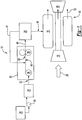
- a gas turbine engine assembly 10 is schematically shown and includes a compressor 14, a combustor 16, and a turbine 18.
- the compressor 14 draws in air 20 and compresses the air to a high pressure.
- the highpressure air is mixed with fuel in the combustor 16 and ignited.
- Hot combustion gases 22 resulting from the ignited fuel drive the turbine 18.
- a Fuel delivery system 12 supplies fuel 40 to the combustor 16. Removing dissolved gasses within the fuel with a fuel de-aerator 28 optimizes a range of flow rates of fuel from the fuel delivery system 12.
- the fuel delivery system 12 includes a fuel-metering unit 29 that receives fuel from a main pump 30.
- the main pump 30 includes a centrifugal pump 36 that supplies fuel at pressure to an inlet 34 of a gear pump 38.
- the gear pump 38 supplies fuel at a constant flow rate to the fuel-metering unit 29.
- Fuel flow 40 from the gear pump 38 remains constant regardless of system 12 backpressure. Excess fuel flow is routed through a bypass passage 41 back to the inlet 34 of the gear pump 38.
- the gear pump 38 includes meshing gears that rotate to compress and drive fuel to the fuel-metering unit 29.
- the centrifugal pump 36 supplies fuel flow to the gear pump 38 to fill cavities between the gears as they rotate.
- the fuel-metering unit 29 controls fuel flow to the combustor 16 of the turbine engine assembly 10. Performance of the turbine engine assembly 10 is limited by the range of operable flow rates provide by the fuel delivery system 12.
- the limiting factor for the flow rates of the fuel delivery system 12 is a net positive suction pressure required at the inlet 34 of the gear pump 38.
- the net positive suction pressure defines the minimum fuel pressure required for operation of the pump 38 without causing cavitations.
- Normal operation of the gear pump 38 requires the actual net suction pressure available at the inlet 34 to be greater than a minimum value.
- a tank boost pump 26 provides a constant fuel pressure to an inlet 32 of the centrifugal pump 36. The constant fuel pressure at the centrifugal pump 36 enables the centrifugal pump 36 to supply fuel at the net positive suction pressure to the inlet 34 of the gear pump 38.
- the minimum net positive suction pressure is greater for air saturated liquid fuel than for de-aerated liquid fuel.
- the greater net positive suction pressure requirements are caused by dissolved gases within the fuel. Exposure to air, such as within the fuel tank, allows gasses to dissolve into the fuel. The static pressure drops as fuel flows from an outlet of the fuel tank 24 to the main fuel pump inlet 32. The reduction in static pressure causes vaporization of dissolved gasses and light hydrocarbons. The presence of dissolved gasses with the liquid fuels increases the minimum required net positive suction pressure.
- the elevated minimum net positive suction pressure limits the range of fuel flow through the fuel delivery system 12.
- a fuel de-aerator 28 is disposed within the fuel system 12 between the tank boost pump 26 and the inlet 32 of the centrifugal pump 36.
- the fuel de-aerator 28 removes dissolved gases from the fuel as the fuel flows from the tank boost pump 26 to the inlet 32 of the centrifugal pump 36.
- the elimination of dissolved gases within the fuel reduces the amount of fuel vapor that forms as a result of reduced static pressures.
- the reduction in fuel vapor decreases the minimum net positive suction pressure required to prevent undesirable cavitation in the gear pump 38.
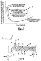
- graph 42 represents the increased ranges of fuel flow provided by removal of dissolved gases from the fuel.
- Line 44 indicates the relationship between fuel flow rate and the net positive suction pressure required at the main fuel pump centrifugal stage. As appreciated, the line 44 is in correspondence with an increased range of fuel flows corresponding to removal of dissolved gases from within the fuel.
- Line 48 corresponds with the operational range for fuel containing dissolved gasses. An operational range of fuel flow rates is shown for fuel containing dissolved gases 48, and fuel with a reduced amount of dissolved gases 44.
- the operational range of fuel flow rate 46 is increased for de-aerated fuels as compared to the operational range of fuel flow rates 50 for air saturated fuels. The resulting increase in the operational range of fuel flow rate provides increased operational capabilities for the engine assembly 10 without requiring a large capacity fuel delivery system 12.
- a schematic view of a fuel de-aerator 28' which is not in accordance with this invention is shown and includes a plurality of tubes 58 disposed within a housing 52.
- the fuel 40 is flowed around the tubes 58 from an inlet 54 to an outlet 56.
- Tubes 58 include a composite permeable membrane 62 that separates oxygen and nitrogen dissolved within the fuel 40.
- a vacuum pump 66 maintains a vacuum within the tubes 58.
- the vacuum created within the tubes 58 creates a partial pressure differential across the composite permeable membrane 62 that draws dissolved oxygen and nitrogen from the fuel 40 into the tubes 58 and out with the gas permeate stream 64 through the vacuum pump 66.
- Oxygen and nitrogen removed from the gas permeate stream 64 is then exhausted from the system.
- the gas permeate stream 64 can be recycled into the fuel tank 24.
- De-aerated fuel exits through the outlet 56 and into the inlet 32 of the centrifugal pump 36.
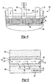
- FIG. 4 an embodiment of a fuel de-aerator 28" in accordance with the invention is shown and includes a series of fuel plates 74 stacked one on top of the other.
- the composite permeable membrane 62 is included on each of the fuel plates 74 to define a portion of fuel passages 76.
- Fuel enters through an inlet 70 and exists through an outlet 72.
- An opening 80 is open to a vacuum source 82.
- Fuel 40 passes within the fuel passages 76 defined by the stacked fuel plates 74.
- the fuel plates 74 are disposed within the housing 68 that defines the inlet 70 and the outlet 72. The use of the fuel plates 74 allows for the adaptation of the fuel de-aerator 28" to various applications by the addition or subtraction of fuel plates 74.
- the composite permeable membrane 62 is shown in cross-section and preferably includes a permeable layer 84 disposed over a porous backing 86.
- the porous backing 86 supplies the required support structure for the permeable layer 84 while still allowing maximum oxygen diffusion from fuel.
- the permeable layer 84 is coated on to the porous backing 84 and a mechanical bond between the two is formed.
- the permeable layer 84 is preferably a 0.5-20 ⁇ m thick coating of Teflon®AF 2400 over a 0.005-in (0.127mm) thick porous backing 86 of polyvinylidene fluoride (PVDF) with a 0.25 ⁇ m pores size.
- PVDF polyvinylidene fluoride
- Other supports of different material, thickness and pore size can be used that provide the requisite strength and openness.
- the permeable layer 84 is Dupont Telfon® AF amorphous fluoropolymer however other materials known to workers skilled in the art are within the contemplation of this invention, such as Solva Hyflon AD perfluorinated glassy polymer and Asahi Glass CYTOP polyperfluorobutenyl vinyl ether.
- Each composite permeable membrane 62 is supported on a porous substrate 88.
- the porous substrate 88 is in communication with the vacuum source 82 to create an oxygen partial pressure differential across the composite permeable
- a partial pressure differential is created by the vacuum source 82 between a non-fuel side 92 of the permeable membrane 62 and a fuel side 90.
- Oxygen, nitrogen and other dissolved gasses indicated at arrows 78 diffuse from fuel 40 across the composite permeable membrane 62 and into the porous substrate 88. From the porous substrate 88 the oxygen, nitrogen and other dissolved gasses 78 are pulled and vented out of the fuel system 12.
- Fuel system 12 of this invention provides for the removal of dissolved gases within the fuel to reduce the minimum required net positive suction pressure.
- the reduction of the net positive suction pressure required improves the operational range of the fuel delivery system 12 above the capacity if liquid and dissolved gases were both present.
- Reduction in the net positive suction pressure improves the operational fuel flow range of the fuel delivery system 12 without increasing the overall size of the fuel delivery system 12.
Landscapes
- Engineering & Computer Science (AREA)
- Chemical & Material Sciences (AREA)
- Combustion & Propulsion (AREA)
- Mechanical Engineering (AREA)
- General Engineering & Computer Science (AREA)
- Chemical Kinetics & Catalysis (AREA)
- Separation Using Semi-Permeable Membranes (AREA)
- Degasification And Air Bubble Elimination (AREA)
- Structures Of Non-Positive Displacement Pumps (AREA)
Claims (6)
- Flugzeugbrennstoffsystem, umfassend:eine Hauptbrennstoffpumpe (30) zum Pumpen von Brennstoff zu einer Brennstoffmessvorrichtung (29); undeine Brennstoffentlüftungsvorrichtung (28") zum Entfernen von aufgelösten Gasen von dem Brennstoff vor dem Eintritt in die Hauptbrennstoffpumpe (30); dadurch gekennzeichnet, dass:die Hauptbrennstoffpumpe eine zweistufige Hauptbrennstoffpumpe mit einer Zentrifugalstufe und einer positiven Verdrängungsstufe ist;die Brennstoffentlüftungsvorrichtung (28") eine Reihe von Brennstoffplatten (74) umfasst, die übereinandergestapelt sind, und die eine Vielzahl von Brennstoffleitungen (76) innerhalb eines Gehäuses (68) zwischen einem Einlass (70) und einem Auslass (72) definieren, wobei eine durchlässige Kompositmembran (62) auf jeder der Brennstoffplatten (74) enthalten ist; und dadurch, dass sie ferner eine Förderpumpe (26) zum Versorgen der Hauptbrennstoffpumpe (30) mit Brennstoff bei einem gewünschten Druck umfasst, wobei die Förderpumpe (26) einen positiven Nettosaugdruck an einem Einlass der Hauptbrennstoffpumpe (30) zuliefert, unddie Brennstoffentlüftungsvorrichtung (28") zwischen der Förderpumpe (26) und der Hauptbrennstoffpumpe (30) angeordnet ist.
- System nach Anspruch 1, wobei die durchlässige Kompositmembran (62) auf einem porösen Substrat (88) getragen wird.
- System nach Anspruch 2, umfassend eine teilweise Druckdifferenz zwischen einer Brennstoffseite der durchlässigen Kompositmembran (62) und einer Nicht-Brennstoffseite der durchlässigen Kompositmembran (62), wobei Gase von Brennstoff durch die durchlässige Kompositmembran (62) zu der Nicht-Brennstoffseite diffundieren.
- System nach Anspruch 3, wobei die diffundierten Gase auf der Nicht-Brennstoffseite über Bord entlüftet werden.
- Gasturbinentriebwerkanordnung, umfassend:einen Verdichter (14), um Einlassluft zu verdichten;eine Brennkammer (16) zum Verbrennen von Brennstoff mit verdichteter Einlassluft;einen Turbinenabschnitt (18), umfassend eine sich drehende Turbine in Flusskommunikation mit der Brennkammer; undein Brennstoffsystem nach einem der vorstehenden Ansprüche.
- Verfahren zum Verbessern von operativer Leistungsfähigkeit des Brennstoffsystems, umfassend folgende Schritte:a) Strömen von brennstoffhaltigen aufgelösten Gasen entlang einer Brennstoffseite einer durchlässigen Kompositmembran (62) innerhalb einer Entlüftungsvorrichtung (28"), wobei die Entlüftungsvorrichtung (28") eine Reihe von Brennstoffplatten (74) umfasst, die übereinandergestapelt sind, und die eine Vielzahl von Brennstoffleitungen (76) innerhalb eines Gehäuses (68) zwischen einem Einlass (70) und einem Auslass (72) definieren, wobei eine durchlässige Kompositmembran (62) auf jeder der Brennstoffplatten (74) enthalten ist;b) Entfernen von aufgelösten Gasen von Brennstoff innerhalb der Entlüftungsvorrichtung (28), wodurch eine teilweise Druckdifferenz zwischen der Brennstoffseite der durchlässigen Kompositmembran (62) und einer Nicht-Brennstoffseite bereitgestellt wird, um die aufgelösten Gase von dem Brennstoff durch die durchlässige Kompositmembran (62) zu diffundieren; undc) Strömen von Brennstoff zu einem Einlass einer Hauptbrennstoffpumpe (30) bei einem benötigten positiven Nettosaugdruck; wobei die Hauptbrennstoffpumpe eine zweistufige Hauptbrennstoffpumpe ist, die ein Zentrifugalstufe und eine positive Verdrängungsstufe aufweist, und weiter umfassend das Pumpen von Brennstoff in die Entlüftungsvorrichtung (28") mit einer Förderpumpe (26), um den benötigten positiven Nettosaugdruck an dem Einlass der Hauptbrennstoffpumpe (30) bereitzustellen, wobei die Brennstoffentlüftungsvorrichtung (28") zwischen der Förderpumpe (26) und der Hauptbrennstoffpumpe (30) angeordnet ist.
Applications Claiming Priority (2)
| Application Number | Priority Date | Filing Date | Title |
|---|---|---|---|
| US10/767,893 US7093437B2 (en) | 2004-01-29 | 2004-01-29 | Extended operability aircraft fuel delivery system |
| US767893 | 2004-01-29 |
Publications (3)
| Publication Number | Publication Date |
|---|---|
| EP1559884A2 EP1559884A2 (de) | 2005-08-03 |
| EP1559884A3 EP1559884A3 (de) | 2008-12-17 |
| EP1559884B1 true EP1559884B1 (de) | 2017-12-13 |
Family
ID=34654363
Family Applications (1)
| Application Number | Title | Priority Date | Filing Date |
|---|---|---|---|
| EP05250350.5A Expired - Lifetime EP1559884B1 (de) | 2004-01-29 | 2005-01-25 | Brennstoffzufuhrsystem mit Entlüftungsvorrichtung für ein Flugtriebwerk und zugehöriges Verfahren |
Country Status (6)
| Country | Link |
|---|---|
| US (2) | US7093437B2 (de) |
| EP (1) | EP1559884B1 (de) |
| JP (1) | JP2005212776A (de) |
| KR (1) | KR20050077733A (de) |
| CN (1) | CN1673502A (de) |
| CA (1) | CA2492309A1 (de) |
Families Citing this family (49)
| Publication number | Priority date | Publication date | Assignee | Title |
|---|---|---|---|---|
| US7231769B2 (en) * | 2004-01-29 | 2007-06-19 | United Technologies Corporation | Gas turbine cooling system |
| US20050274649A1 (en) * | 2004-06-09 | 2005-12-15 | Spadaccini Louis J | Method for suppressing oxidative coke formation in liquid hydrocarbons containing metal |
| US7571596B2 (en) * | 2005-12-14 | 2009-08-11 | Hamilton Sundstrand Corporation | Vacuum system for membrane fuel stabilization unit |
| DE102006007868A1 (de) * | 2006-02-17 | 2007-08-30 | Boehringer Ingelheim Microparts Gmbh | Membranaufbau zur Gasabscheidung, Entgasungsvorrichtung mit einem derartigen Membranaufbau sowie Verfahren zur Herstellung |
| US8465266B2 (en) * | 2007-10-12 | 2013-06-18 | United Technologies Corp. | Vacuum pressure systems |
| US7784448B2 (en) * | 2008-04-24 | 2010-08-31 | Rolls-Royce Corporation | Fuel flow anti-interruption |
| WO2009139801A2 (en) | 2008-05-13 | 2009-11-19 | Sikorsky Aircraft Corporation | Offset ambient level fuel feed system |
| US8234870B2 (en) * | 2009-04-17 | 2012-08-07 | Hamilton Sundstrand Corporation | Additive injection system for improving thermal stability of jet fuel |
| JP2013221410A (ja) * | 2012-04-12 | 2013-10-28 | Fuji Heavy Ind Ltd | 航空機燃料の脱気システム及び航空機燃料の脱気方法 |
| CN102758711B (zh) * | 2012-08-02 | 2015-05-13 | 合肥威尔燃油系统有限责任公司 | 具有排气功能的燃油滤清器 |
| US20140345700A1 (en) * | 2013-05-22 | 2014-11-27 | Hamilton Sundstrand Corporation | Pressure monitoring system for a fuel tank and method |
| US9989060B2 (en) * | 2013-08-08 | 2018-06-05 | Woodward, Inc. | Fuel system with liquid ring pump with centrifugal air/fuel separator |
| US9687773B2 (en) | 2014-04-30 | 2017-06-27 | Honeywell International Inc. | Fuel deoxygenation and fuel tank inerting system and method |
| US9656187B2 (en) | 2014-11-12 | 2017-05-23 | Honeywell International Inc. | Fuel deoxygenation system contactor-separator |
| US9834315B2 (en) | 2014-12-15 | 2017-12-05 | Honeywell International Inc. | Aircraft fuel deoxygenation system |
| US9897054B2 (en) | 2015-01-15 | 2018-02-20 | Honeywell International Inc. | Centrifugal fuel pump with variable pressure control |
| US9856836B2 (en) * | 2015-06-25 | 2018-01-02 | Woodward, Inc. | Variable fluid flow apparatus with integrated filter |
| US10215097B2 (en) * | 2015-12-08 | 2019-02-26 | General Electric Company | Thermal management system |
| FR3061240B1 (fr) * | 2016-12-22 | 2019-05-31 | Safran Aircraft Engines | Procede ameliore de regulation d'un circuit d'alimentation |
| FR3064305B1 (fr) * | 2017-03-21 | 2019-03-22 | Safran Helicopter Engines | Degazeur centrifuge de turbomachine |
| US11235846B2 (en) * | 2017-04-21 | 2022-02-01 | Newsouth Innovations Pty Limited | Prevention of cavitation |
| US11148824B2 (en) | 2018-11-02 | 2021-10-19 | General Electric Company | Fuel delivery system having a fuel oxygen reduction unit |
| US11131256B2 (en) | 2018-11-02 | 2021-09-28 | General Electric Company | Fuel oxygen conversion unit with a fuel/gas separator |
| US11577852B2 (en) | 2018-11-02 | 2023-02-14 | General Electric Company | Fuel oxygen conversion unit |
| US11085636B2 (en) | 2018-11-02 | 2021-08-10 | General Electric Company | Fuel oxygen conversion unit |
| US11193671B2 (en) | 2018-11-02 | 2021-12-07 | General Electric Company | Fuel oxygen conversion unit with a fuel gas separator |
| US11447263B2 (en) | 2018-11-02 | 2022-09-20 | General Electric Company | Fuel oxygen reduction unit control system |
| US11161622B2 (en) | 2018-11-02 | 2021-11-02 | General Electric Company | Fuel oxygen reduction unit |
| US11319085B2 (en) | 2018-11-02 | 2022-05-03 | General Electric Company | Fuel oxygen conversion unit with valve control |
| US11186382B2 (en) | 2018-11-02 | 2021-11-30 | General Electric Company | Fuel oxygen conversion unit |
| US11420763B2 (en) | 2018-11-02 | 2022-08-23 | General Electric Company | Fuel delivery system having a fuel oxygen reduction unit |
| US11851204B2 (en) | 2018-11-02 | 2023-12-26 | General Electric Company | Fuel oxygen conversion unit with a dual separator pump |
| US11015534B2 (en) | 2018-11-28 | 2021-05-25 | General Electric Company | Thermal management system |
| US11391211B2 (en) | 2018-11-28 | 2022-07-19 | General Electric Company | Waste heat recovery system |
| US20220088505A1 (en) * | 2019-01-29 | 2022-03-24 | Donaldson Company, Inc. | System and method for deaeration |
| US12025054B2 (en) | 2019-04-05 | 2024-07-02 | General Electric Company | Pump mixer separator unit |
| US10914274B1 (en) | 2019-09-11 | 2021-02-09 | General Electric Company | Fuel oxygen reduction unit with plasma reactor |
| US12274958B2 (en) | 2019-10-23 | 2025-04-15 | Donaldson Company, Inc. | Filtration and deaeration system |
| US11774427B2 (en) | 2019-11-27 | 2023-10-03 | General Electric Company | Methods and apparatus for monitoring health of fuel oxygen conversion unit |
| US11773776B2 (en) | 2020-05-01 | 2023-10-03 | General Electric Company | Fuel oxygen reduction unit for prescribed operating conditions |
| US11866182B2 (en) | 2020-05-01 | 2024-01-09 | General Electric Company | Fuel delivery system having a fuel oxygen reduction unit |
| US11906163B2 (en) | 2020-05-01 | 2024-02-20 | General Electric Company | Fuel oxygen conversion unit with integrated water removal |
| JP7807426B2 (ja) * | 2020-07-14 | 2026-01-27 | ドナルドソン カンパニー,インコーポレイティド | 脱気のシステム及び方法 |
| US11434824B2 (en) | 2021-02-03 | 2022-09-06 | General Electric Company | Fuel heater and energy conversion system |
| US11591965B2 (en) | 2021-03-29 | 2023-02-28 | General Electric Company | Thermal management system for transferring heat between fluids |
| US12139270B2 (en) | 2021-04-19 | 2024-11-12 | General Electric Company | Aircraft thermal transport system and method |
| US12115470B2 (en) | 2021-04-27 | 2024-10-15 | General Electric Company | Fuel oxygen reduction unit |
| US12005377B2 (en) | 2021-06-15 | 2024-06-11 | General Electric Company | Fuel oxygen reduction unit with level control device |
| US11542870B1 (en) | 2021-11-24 | 2023-01-03 | General Electric Company | Gas supply system |
Citations (1)
| Publication number | Priority date | Publication date | Assignee | Title |
|---|---|---|---|---|
| EP1677888A1 (de) * | 2003-09-08 | 2006-07-12 | United Technologies Corporation | System und verfahren für thermomanagement |
Family Cites Families (16)
| Publication number | Priority date | Publication date | Assignee | Title |
|---|---|---|---|---|
| US2781831A (en) * | 1952-09-11 | 1957-02-19 | Thompson Prod Inc | Pumping assembly |
| US3751879A (en) * | 1971-04-26 | 1973-08-14 | Instrumentation Specialties Co | Apparatus for reducing the dissolved gas concentration in a liquid |
| FR2535408A1 (fr) * | 1982-10-28 | 1984-05-04 | Snecma | Dispositif et procede de detection de la garde a la cavitation d'une pompe volumetrique |
| GB8409999D0 (en) * | 1984-04-17 | 1984-05-31 | Plessey Co Plc | Fuel supply system |
| GB2158157B (en) | 1984-04-17 | 1987-12-31 | Plessey Co Plc | De-aerating an aircraft engines fuel supply |
| WO1992007179A1 (en) * | 1990-10-15 | 1992-04-30 | Allied-Signal Inc. | Fuel supply system |
| US5597418A (en) * | 1994-09-30 | 1997-01-28 | New Pig Corporation | Method of making foldable mat for absorbing liquids |
| US5504256A (en) * | 1995-03-10 | 1996-04-02 | Exxon Research And Engineering Company | Catalytic production of aryl alkyl hydroperoxides by polynuclear transition metal aggregates (LAW229) |
| US5888275A (en) * | 1996-02-26 | 1999-03-30 | Japan Gore-Tex, Inc. | Assembly for deaeration of liquids |
| US5876604A (en) * | 1996-10-24 | 1999-03-02 | Compact Membrane Systems, Inc | Method of gasifying or degasifying a liquid |
| US5992920A (en) * | 1998-06-23 | 1999-11-30 | R-Vision | Foldout recreational vehicle |
| EP0973031B1 (de) * | 1998-07-17 | 2005-01-12 | Agilent Technologies, Inc. (a Delaware corporation) | Vorrichtung zum Entgasen von Flüssigkeiten |
| US6290760B1 (en) * | 1999-04-30 | 2001-09-18 | Tokheim Corporation | Air separator system |
| US6315815B1 (en) * | 1999-12-16 | 2001-11-13 | United Technologies Corporation | Membrane based fuel deoxygenator |
| US6647730B2 (en) * | 2001-10-31 | 2003-11-18 | Pratt & Whitney Canada Corp. | Turbine engine having turbine cooled with diverted compressor intermediate pressure air |
| US6709492B1 (en) * | 2003-04-04 | 2004-03-23 | United Technologies Corporation | Planar membrane deoxygenator |
-
2004
- 2004-01-29 US US10/767,893 patent/US7093437B2/en not_active Expired - Lifetime
-
2005
- 2005-01-13 CA CA002492309A patent/CA2492309A1/en not_active Abandoned
- 2005-01-14 KR KR1020050003522A patent/KR20050077733A/ko not_active Abandoned
- 2005-01-25 EP EP05250350.5A patent/EP1559884B1/de not_active Expired - Lifetime
- 2005-01-26 JP JP2005018874A patent/JP2005212776A/ja active Pending
- 2005-01-31 CN CNA2005100061773A patent/CN1673502A/zh active Pending
-
2006
- 2006-04-13 US US11/403,755 patent/US7231768B2/en not_active Expired - Lifetime
Patent Citations (1)
| Publication number | Priority date | Publication date | Assignee | Title |
|---|---|---|---|---|
| EP1677888A1 (de) * | 2003-09-08 | 2006-07-12 | United Technologies Corporation | System und verfahren für thermomanagement |
Also Published As
| Publication number | Publication date |
|---|---|
| US20060179845A1 (en) | 2006-08-17 |
| CN1673502A (zh) | 2005-09-28 |
| US7093437B2 (en) | 2006-08-22 |
| EP1559884A3 (de) | 2008-12-17 |
| US7231768B2 (en) | 2007-06-19 |
| EP1559884A2 (de) | 2005-08-03 |
| KR20050077733A (ko) | 2005-08-03 |
| CA2492309A1 (en) | 2005-07-29 |
| US20050166597A1 (en) | 2005-08-04 |
| JP2005212776A (ja) | 2005-08-11 |
Similar Documents
| Publication | Publication Date | Title |
|---|---|---|
| EP1559884B1 (de) | Brennstoffzufuhrsystem mit Entlüftungsvorrichtung für ein Flugtriebwerk und zugehöriges Verfahren | |
| US7445659B2 (en) | Ejector to reduce permeate backpressure of air separation module | |
| EP1559883B1 (de) | Gasturbine mit einem Brennstoffentgaser | |
| US20160305440A1 (en) | In-line continuous flow liquid-gas separator-pump | |
| EP1464376A1 (de) | Entgaser mit Flachmembranen | |
| CN100520011C (zh) | 操作燃气涡轮发动机的方法和装置 | |
| EP1810741A2 (de) | Brennstoffentgaser mit nicht planarem Brennstoffkanal und sauerstoffdurchlässiger Membran | |
| US20100098525A1 (en) | Pump System And Method For Delivering Multi-Phase Mixtures | |
| US20210379527A1 (en) | Vacuum assisted air separation module operation | |
| US20050137441A1 (en) | Multi-stage fuel deoxygenator | |
| EP3318728B1 (de) | Lagergehäuse mit variablem volumen | |
| US7615104B2 (en) | Fuel deoxygenation system with multi-layer oxygen permeable membrane | |
| JP6029421B2 (ja) | 窒素富化ガス供給システム、航空機 | |
| US7578870B2 (en) | Fluid separating device | |
| CN111473235B (zh) | 油清除系统 | |
| CN114396383A (zh) | 一种油汽混输系统 | |
| US20020192082A1 (en) | Method for the fuel supply and a fuel supply system for aircraft equipped with at least one aero gas turbine | |
| CN105531483B (zh) | 具有包括离心式空气/燃料分离器的液环泵的燃料系统 | |
| RU2256810C1 (ru) | Система суфлирования масляной опоры ротора газотурбинного двигателя | |
| CN117295883A (zh) | 用于飞行器发动机的燃料供应系统 | |
| JP7679819B2 (ja) | 燃料電池車 | |
| US8790090B2 (en) | Priming of gear pump in alternative attitudes | |
| EP3539880B1 (de) | Kavitationsminderung in kraftstofftankinertisierungssystemen mit katalytischer oxidation | |
| CN118669214A (zh) | 一种飞行器涡喷发动机的双重稳压燃油供应系统 | |
| CN115478942A (zh) | 带有水平控制装置的燃料氧减少单元 |
Legal Events
| Date | Code | Title | Description |
|---|---|---|---|
| PUAI | Public reference made under article 153(3) epc to a published international application that has entered the european phase |
Free format text: ORIGINAL CODE: 0009012 |
|
| AK | Designated contracting states |
Kind code of ref document: A2 Designated state(s): AT BE BG CH CY CZ DE DK EE ES FI FR GB GR HU IE IS IT LI LT LU MC NL PL PT RO SE SI SK TR |
|
| AX | Request for extension of the european patent |
Extension state: AL BA HR LV MK YU |
|
| PUAL | Search report despatched |
Free format text: ORIGINAL CODE: 0009013 |
|
| AK | Designated contracting states |
Kind code of ref document: A3 Designated state(s): AT BE BG CH CY CZ DE DK EE ES FI FR GB GR HU IE IS IT LI LT LU MC NL PL PT RO SE SI SK TR |
|
| AX | Request for extension of the european patent |
Extension state: AL BA HR LV MK YU |
|
| RIC1 | Information provided on ipc code assigned before grant |
Ipc: B01D 19/00 20060101ALI20081111BHEP Ipc: F02C 7/236 20060101AFI20050421BHEP |
|
| 17P | Request for examination filed |
Effective date: 20090617 |
|
| AKX | Designation fees paid |
Designated state(s): DE GB |
|
| 17Q | First examination report despatched |
Effective date: 20111012 |
|
| RAP1 | Party data changed (applicant data changed or rights of an application transferred) |
Owner name: UNITED TECHNOLOGIES CORPORATION |
|
| STAA | Information on the status of an ep patent application or granted ep patent |
Free format text: STATUS: EXAMINATION IS IN PROGRESS |
|
| GRAP | Despatch of communication of intention to grant a patent |
Free format text: ORIGINAL CODE: EPIDOSNIGR1 |
|
| STAA | Information on the status of an ep patent application or granted ep patent |
Free format text: STATUS: GRANT OF PATENT IS INTENDED |
|
| INTG | Intention to grant announced |
Effective date: 20170726 |
|
| GRAS | Grant fee paid |
Free format text: ORIGINAL CODE: EPIDOSNIGR3 |
|
| GRAA | (expected) grant |
Free format text: ORIGINAL CODE: 0009210 |
|
| STAA | Information on the status of an ep patent application or granted ep patent |
Free format text: STATUS: THE PATENT HAS BEEN GRANTED |
|
| AK | Designated contracting states |
Kind code of ref document: B1 Designated state(s): DE GB |
|
| REG | Reference to a national code |
Ref country code: GB Ref legal event code: FG4D |
|
| REG | Reference to a national code |
Ref country code: DE Ref legal event code: R096 Ref document number: 602005053205 Country of ref document: DE |
|
| REG | Reference to a national code |
Ref country code: DE Ref legal event code: R097 Ref document number: 602005053205 Country of ref document: DE |
|
| PLBE | No opposition filed within time limit |
Free format text: ORIGINAL CODE: 0009261 |
|
| STAA | Information on the status of an ep patent application or granted ep patent |
Free format text: STATUS: NO OPPOSITION FILED WITHIN TIME LIMIT |
|
| 26N | No opposition filed |
Effective date: 20180914 |
|
| PGFP | Annual fee paid to national office [announced via postgrant information from national office to epo] |
Ref country code: DE Payment date: 20191218 Year of fee payment: 16 |
|
| REG | Reference to a national code |
Ref country code: DE Ref legal event code: R119 Ref document number: 602005053205 Country of ref document: DE |
|
| PG25 | Lapsed in a contracting state [announced via postgrant information from national office to epo] |
Ref country code: DE Free format text: LAPSE BECAUSE OF NON-PAYMENT OF DUE FEES Effective date: 20210803 |
|
| PGFP | Annual fee paid to national office [announced via postgrant information from national office to epo] |
Ref country code: GB Payment date: 20231219 Year of fee payment: 20 |
|
| REG | Reference to a national code |
Ref country code: GB Ref legal event code: PE20 Expiry date: 20250124 |
|
| PG25 | Lapsed in a contracting state [announced via postgrant information from national office to epo] |
Ref country code: GB Free format text: LAPSE BECAUSE OF EXPIRATION OF PROTECTION Effective date: 20250124 |