EP2969100B1 - Deoxygenierung von flussigkeit mit gas - Google Patents
Deoxygenierung von flussigkeit mit gas Download PDFInfo
- Publication number
- EP2969100B1 EP2969100B1 EP13818106.0A EP13818106A EP2969100B1 EP 2969100 B1 EP2969100 B1 EP 2969100B1 EP 13818106 A EP13818106 A EP 13818106A EP 2969100 B1 EP2969100 B1 EP 2969100B1
- Authority
- EP
- European Patent Office
- Prior art keywords
- liquid
- lumen
- transport
- gas
- fuel
- Prior art date
- Legal status (The legal status is an assumption and is not a legal conclusion. Google has not performed a legal analysis and makes no representation as to the accuracy of the status listed.)
- Active
Links
- 239000007788 liquid Substances 0.000 title claims description 65
- 238000006392 deoxygenation reaction Methods 0.000 title 1
- 239000000446 fuel Substances 0.000 claims description 71
- 239000007789 gas Substances 0.000 claims description 47
- 238000006213 oxygenation reaction Methods 0.000 claims description 26
- 239000012530 fluid Substances 0.000 claims description 19
- QVGXLLKOCUKJST-UHFFFAOYSA-N atomic oxygen Chemical compound [O] QVGXLLKOCUKJST-UHFFFAOYSA-N 0.000 claims description 17
- 238000010008 shearing Methods 0.000 claims description 17
- 239000001301 oxygen Substances 0.000 claims description 15
- 229910052760 oxygen Inorganic materials 0.000 claims description 15
- 238000000034 method Methods 0.000 claims description 14
- IJGRMHOSHXDMSA-UHFFFAOYSA-N Atomic nitrogen Chemical compound N#N IJGRMHOSHXDMSA-UHFFFAOYSA-N 0.000 claims description 6
- 230000009467 reduction Effects 0.000 claims description 6
- 238000000926 separation method Methods 0.000 claims description 6
- 239000004215 Carbon black (E152) Substances 0.000 claims description 4
- 229930195733 hydrocarbon Natural products 0.000 claims description 4
- 150000002430 hydrocarbons Chemical class 0.000 claims description 4
- 230000037361 pathway Effects 0.000 claims description 4
- 229910052757 nitrogen Inorganic materials 0.000 claims description 3
- 238000004891 communication Methods 0.000 claims description 2
- 230000008569 process Effects 0.000 description 4
- 230000004888 barrier function Effects 0.000 description 2
- 230000010354 integration Effects 0.000 description 2
- 230000003993 interaction Effects 0.000 description 2
- 230000004075 alteration Effects 0.000 description 1
- 238000005119 centrifugation Methods 0.000 description 1
- 239000000571 coke Substances 0.000 description 1
- 238000010586 diagram Methods 0.000 description 1
- 238000005516 engineering process Methods 0.000 description 1
- 239000002828 fuel tank Substances 0.000 description 1
- 230000003116 impacting effect Effects 0.000 description 1
- 239000012528 membrane Substances 0.000 description 1
- 238000007670 refining Methods 0.000 description 1
- 238000009987 spinning Methods 0.000 description 1
- 230000003068 static effect Effects 0.000 description 1
- 238000003756 stirring Methods 0.000 description 1
- 239000000126 substance Substances 0.000 description 1
- 238000006467 substitution reaction Methods 0.000 description 1
Images
Classifications
-
- B—PERFORMING OPERATIONS; TRANSPORTING
- B01—PHYSICAL OR CHEMICAL PROCESSES OR APPARATUS IN GENERAL
- B01D—SEPARATION
- B01D19/00—Degasification of liquids
- B01D19/0005—Degasification of liquids with one or more auxiliary substances
-
- B—PERFORMING OPERATIONS; TRANSPORTING
- B01—PHYSICAL OR CHEMICAL PROCESSES OR APPARATUS IN GENERAL
- B01D—SEPARATION
- B01D19/00—Degasification of liquids
- B01D19/0036—Flash degasification
-
- B—PERFORMING OPERATIONS; TRANSPORTING
- B01—PHYSICAL OR CHEMICAL PROCESSES OR APPARATUS IN GENERAL
- B01D—SEPARATION
- B01D19/00—Degasification of liquids
- B01D19/0042—Degasification of liquids modifying the liquid flow
Definitions
- some embodiments of the disclosure relate to the field of removal of dissolved oxygen from liquid hydrocarbon fuels.
- de-oxygenated fuel is known to have increased thermal stability. This means that de-oxygenated fuel can absorb more heat, resulting in higher fuel temperature, without forming flow-reducing coke deposits.
- de-oxygenated fuel can absorb more heat, resulting in higher fuel temperature, without forming flow-reducing coke deposits.
- gas turbine engines such a higher heat capacity fuel can enhance low emission fuel systems, can be used as an effective heat sink for engine and aircraft heat loads, and can reduce engine fuel consumption.
- An exemplary system for removing oxygen from fuel is described herein and is shown in the attached drawings.
- the system utilizes a process similar to those used in effervescent atomizers to inject gas into a flowing liquid.
- the dissolved oxygen in the liquid diffuses into the resultant gas bubbles in an established process referred to as sparging.
- the present disclosure makes use of such techniques in order to remove dissolved oxygen from hydrocarbon fuels.
- FIG. 1 is an illustration of a fluid de-oxygenation system 10 in accordance with one embodiment of the present disclosure.
- the system 10 includes a liquid/fuel source 12 that is transported by way of a liquid/fuel pump 14 into a liquid/fuel transport lumen 16.
- the liquid transport lumen 16 may be any of a variety of transport pathways, although a smooth walled tube is preferred.
- the use of a smooth walled liquid transport lumen 16 without mixing vanes or barriers ensures proper flow of the transport liquid/fuel 18 through the de-oxygenation system 10 and prevents build-up or blockages from impacting performance.
- the present disclosure is applicable to a variety of liquids, the present disclosure contemplates the transport liquid/fuel 18 to be a hydrocarbon fuel in one embodiment.
- the liquid/fuel transport lumen 16 includes a plurality of openings 20 formed therein. It is contemplated that these openings may comprise a variety of shapes, quantity, spacing, and diameter configured to produce turbulent mixing of gas bubbles into fuel 18 flowing within the liquid/fuel transport lumen 16. The size of each of the plurality of openings 20 may be large enough to prevent blockages from imperfections in the liquid/fuel 18.
- the portion of the liquid/fuel transport lumen 16 containing the openings 20 is positioned within a pressurized gas lumen 22 or similar enclosure.
- the pressurized gas lumen 22 is in communication with a gas source 24 which fills the pressurized gas lumen 22 with a de-oxygenating gas 26.
- de-oxygenating gases 26 Although a variety of de-oxygenating gases 26 are contemplated, one embodiment contemplates the use of nitrogen. Another embodiment contemplates the use of air (i.e., about 78% nitrogen). It should be understood, however, that any gas that attracts dissolved oxygen from a liquid could be utilized.
- the pressurized de-oxygenating gas 26 fills the pressurized gas lumen 22 and passes through the plurality of openings 20 and into the transport liquid/fuel 18 as it passes through the liquid/fuel transport lumen 16.
- the pressurized gas lumen 22 may support the liquid/fuel transport lumen 16 on either end of the openings 20.
- the de-oxygenating gas 26 enters the transport liquid/fuel 18 along an extended length of the liquid/fuel transport lumen 16 as the liquid/fuel 18 is flowing. This allows turbulent mixing of a plurality of small bubbles of the de-oxygenating gas 26 and the fuel 18. Any dissolved oxygen in the liquid fuel diffuses to the plurality of small gas bubbles in a process referred to as sparging.
- the present disclosure further includes a shearing feature 28 located in or on the liquid/fuel transport lumen 16.
- the shearing feature 28 is intended to encompass any feature that changes pressure and applies shear and compressive forces to the bubbles.
- the shearing feature 28 acts to collapse the plurality of small bubbles into larger ones making them easier to separate downstream.
- the shearing feature 28 comprises a sudden reduction in lumen cross-section such as an orifice shaped reduction or a convergent nozzle.
- the shearing feature 28 variables, e.g., without limitation, shape and length and diameter, may be selected to better collapse the bubbly flow. It would be understood to one skilled in the art, in light of the present disclosure, that a variety of alterations or substitutions could be utilized to reduce the number of bubbles and increase their size.
- the now de-oxygenated fuel moves from the shearing feature 28, through a continued flow section 30 of the liquid/fuel transport lumen 16 and into a gas/liquid separation device 32.
- the gas/liquid separation device 32 separates and separately expels the oxygen-rich gas 34 and the de-oxygenated fuel 36. It is contemplated that the gas/liquid separation device 32 may utilize any of a variety of techniques to separate the gas and liquid/fuel such as, but not limited to, spinning/centrifugation.
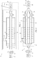
- FIG. 2 is an illustration of a fluid de-oxygenation system 10 in accordance with another embodiment of the present disclosure.
- the liquid/fuel transport lumen 16 may actually comprise a plurality of liquid/fuel transport lumens 16, 16'.
- Each of these liquid/fuel transport lumens 16, 16' contains a plurality of openings 20, 20' along its length within the pressurized gas lumen 22. This provides a more controlled and efficient de-oxygenation of the fuel 18 as it passes through the pressurized gas lumen 22. It also allows for a reduction in overall size of the fluid de-oxygenation system 10. This may allow such an embodiment to be placed on-board aircraft or other vehicles for on-board fuel processing.
- each of the liquid/fuel transport lumens 16, 16' also includes its own shearing feature 28, 28' and continued flow section 30, 30' to further tailor the fuel de-oxygenation prior to flow into the gas/liquid separation device 32.
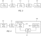
- FIG. 3 illustrates the fluid de-oxygenation system 10 of the present disclosure which can be utilized at any of one or more points in the jet fuel supply chain where the fuel is flowing including its eventual consumption in a gas turbine engine.
- Oxygen may be introduced during any period of fuel exposure prior to usage.
- the system 10 may be utilized during fuel pumped between fuel processing plants 100 and fuel storage 110. Similarly the system 10 may be set up to function on fuel as it is moved between fuel storage 110 and transportation means 120 such as trucks or pipelines. In this fashion, the oxygen may be removed from the fuel at any stage along the supply chain.
- Figure 4 further illustrates the flexibility of the fluid de-oxygenation system 10.
- the system 10 may be utilized between an external fuel storage tank 130 and a vehicle/aircraft 140 such that oxygen may be removed from the fuel as it is transferred from the external fuel storage tank 130 to the vehicle/aircraft 140.
- the system 10 due to its flexibility, provides for in-line functioning and may be integrated directly into the vehicle/aircraft 140 such that it operates as fuel is transferred from the vehicle/aircraft 140 internal fuel tank 150 to the vehicle/aircraft engine/turbine 160. This portability and flexibility has not been previously available for fuel de-oxygenation systems.
Landscapes
- Chemical & Material Sciences (AREA)
- Chemical Kinetics & Catalysis (AREA)
- Degasification And Air Bubble Elimination (AREA)
Claims (14)
- Flüssigkeits-Deoxygenierungssystem (10), umfassend:ein Druckgas-Lumen (22), enthaltend deoxygenierendes Druckgas (26); undein Flüssigkeitstransport-Lumen (16, 16'), das in dem Druckgas-Lumen angeordnet ist und das Druckgas-Lumen (22) durchläuft, das Flüssigkeitstransport-Lumen (16, 16') enthaltend eine Mehrzahl von Öffnungen (20), die entlang seiner Länge innerhalb des Druckgas-Lumens (22) ausgebildet sind, eine Schereinrichtung (28, 28'), welche der Mehrzahl von Öffnungen (20) nachgelagert ist, und einen Weiterströmungsabschnitt (30, 30'), welcher der Schereinrichtung (28, 28') nachgelagert ist;
wobei die Schereinrichtung eine plötzliche Verringerung des Lumenquerschnitts umfasst;wobei das deoxygenierende Gas (26) durch die Mehrzahl von Öffnungen (20) in das Flüssigkeitstransport-Lumen (16, 16') eintritt, um eine Mehrzahl von Blasen in einer Transportflüssigkeit (18) zu bilden, wobei durch die Mehrzahl von Blasen aus der Transportflüssigkeit (18) Sauerstoff (34) entfernt wird;
wobei die Schereinrichtung (28, 28') vor dem Strömen in den Weiterströmungsabschnitt (30, 30') die Mehrzahl von Blasen in größere Blasen kollabiert. - Flüssigkeits-Deoxygenierungssystem (10) nach Anspruch 1, wobei das Flüssigkeitstransport-Lumen (16, 16') ein glattwandiges Rohr umfasst.
- Flüssigkeits-Deoxygenierungssystem (10) nach einem der Ansprüche 1 und 2, wobei die Schereinrichtung (28, 28') eine Querschnittsverringerung des Lumens (16, 16') umfasst.
- Flüssigkeits-Deoxygenierungssystem (10) nach einem der Ansprüche 1 bis 3, ferner umfassend:
eine Gas/Flüssig-Trennvorrichtung (32), die mit dem Weiterströmungsabschnitt (30, 30') in Kommunikation steht. - Flüssigkeits-Deoxygenierungssystem (10) nach einem der vorangehenden Ansprüche, wobei die Transportflüssigkeit (18) einen Kohlenwasserstoff-Brennstoff umfassen kann und das deoxygenierende Gas (26) Stickstoff umfassen kann.
- Flüssigkeits-Deoxygenierungssystem (10) nach einem der vorangehenden Ansprüche, ferner umfassend:
mindestens ein zusätzliches Flüssigkeitstransport-Lumen (16, 16'), das in dem Druckgas-Lumen (22) angeordnet ist, das zusätzliche Flüssigkeitstransport-Lumen (16, 16') enthaltend eine Mehrzahl von Öffnungen (20), die entlang seiner Länge innerhalb des Druckgas-Lumens (22) ausgebildet sind. - Flüssigkeits-Deoxygenierungssystem (10) nach Anspruch 6, wobei jedes der zusätzlichen Flüssigkeitstransport-Lumen (16, 16') eine Schereinrichtung (28, 28') enthält, welche der Mehrzahl von Öffnungen (20) nachgelagert ist.
- Flüssigkeits-Deoxygenierungssystem (10) nach einem der vorangehenden Ansprüche, wobei die Schereinrichtung (28, 28') eine konvergente Düse umfasst.
- Verfahren zur Brennstoff-Deoxygenierung, umfassend:Transportieren einer Transportflüssigkeit (18) durch ein Flüssigkeitstransport-Lumen (16, 16'), das in einem Druckgas-Lumen (22) angeordnet ist, das Flüssigkeitstransport-Lumen (16, 16') enthaltend eine Mehrzahl von Öffnungen (20), die entlang seiner Länge innerhalb des Druckgas-Lumens (22) ausgebildet sind;Zuführen eines deoxygenierenden Druckgases (26) in das Druckgas-Lumen (22), so dass das deoxygenierende Gas (26) durch die Mehrzahl von Öffnungen (20) in das Flüssigkeitstransport-Lumen (16, 16') eintritt, um eine Mehrzahl von Blasen in einer Transportflüssigkeit (18) zu bilden, wobei durch die Mehrzahl von Blasen aus der Transportflüssigkeit (18) Sauerstoff (34) entfernt wird;Drücken der Transportflüssigkeit (18) durch eine Schereinrichtung (28, 28'), welche der Mehrzahl von Öffnungen (20) nachgelagert ist, so dass die Mehrzahl von Blasen in größere Blasen kollabiert werden;wobei die Schereinrichtung eine plötzliche Verringerung des Lumenquerschnitts umfasst;Weiterführen der Transportflüssigkeit (18) in einen Weiterströmungsabschnitt (30, 30'), welcher der Schereinrichtung (28, 28') nachgelagert ist.
- Verfahren nach Anspruch 9, ferner umfassend:
Weiterführen der Transportflüssigkeit (18) aus dem Weiterströmungsabschnitt (30, 30') in eine Gas/Flüssig-Trennvorrichtung (32), um Gas (34, 36) aus der Transportflüssigkeit (18) zu entfernen. - Verfahren nach einem der Ansprüche 9 und 10, wobei das Flüssigkeitstransport-Lumen (16, 16') ein glattwandiges Rohr umfasst.
- Verfahren nach einem der Ansprüche 9 bis 11, wobei der Schritt des Transportierens einer Transportflüssigkeit (18) durch ein Flüssigkeitstransport-Lumen (16, 16') umfasst:
Transportieren der Transportflüssigkeit (18) durch eine Mehrzahl von Flüssigkeitstransport-Lumen (16, 16'), die in dem Druckgas-Lumen (22) angeordnet sind, jedes der Mehrzahl von Flüssigkeitstransport-Lumen (16, 16') enthaltend eine Mehrzahl von Öffnungen (20), die entlang seiner Länge innerhalb des Druckgas-Lumens (22) ausgebildet sind. - Verfahren nach einem der Ansprüche 9 bis 12, wobei das Verfahren an Bord eines Luftfahrzeugs (140) durchgeführt wird.
- Verfahren nach einem der Ansprüche 9 bis 13, wobei das Verfahren an einer Mehrzahl von Orten (100, 110, 120, 130) entlang eines Brennstoffdurchführungsweges durchgeführt wird.
Applications Claiming Priority (2)
| Application Number | Priority Date | Filing Date | Title |
|---|---|---|---|
| US201361778278P | 2013-03-12 | 2013-03-12 | |
| PCT/US2013/075496 WO2014163685A1 (en) | 2013-03-12 | 2013-12-16 | Deoxygenation of liquid with gas |
Publications (2)
| Publication Number | Publication Date |
|---|---|
| EP2969100A1 EP2969100A1 (de) | 2016-01-20 |
| EP2969100B1 true EP2969100B1 (de) | 2018-06-13 |
Family
ID=49918874
Family Applications (1)
| Application Number | Title | Priority Date | Filing Date |
|---|---|---|---|
| EP13818106.0A Active EP2969100B1 (de) | 2013-03-12 | 2013-12-16 | Deoxygenierung von flussigkeit mit gas |
Country Status (3)
| Country | Link |
|---|---|
| US (1) | US9162162B2 (de) |
| EP (1) | EP2969100B1 (de) |
| WO (1) | WO2014163685A1 (de) |
Families Citing this family (23)
| Publication number | Priority date | Publication date | Assignee | Title |
|---|---|---|---|---|
| US11193671B2 (en) | 2018-11-02 | 2021-12-07 | General Electric Company | Fuel oxygen conversion unit with a fuel gas separator |
| US11577852B2 (en) | 2018-11-02 | 2023-02-14 | General Electric Company | Fuel oxygen conversion unit |
| US11131256B2 (en) | 2018-11-02 | 2021-09-28 | General Electric Company | Fuel oxygen conversion unit with a fuel/gas separator |
| US11085636B2 (en) | 2018-11-02 | 2021-08-10 | General Electric Company | Fuel oxygen conversion unit |
| US11161622B2 (en) | 2018-11-02 | 2021-11-02 | General Electric Company | Fuel oxygen reduction unit |
| US11447263B2 (en) | 2018-11-02 | 2022-09-20 | General Electric Company | Fuel oxygen reduction unit control system |
| US11148824B2 (en) | 2018-11-02 | 2021-10-19 | General Electric Company | Fuel delivery system having a fuel oxygen reduction unit |
| US11420763B2 (en) | 2018-11-02 | 2022-08-23 | General Electric Company | Fuel delivery system having a fuel oxygen reduction unit |
| US11851204B2 (en) | 2018-11-02 | 2023-12-26 | General Electric Company | Fuel oxygen conversion unit with a dual separator pump |
| US11319085B2 (en) | 2018-11-02 | 2022-05-03 | General Electric Company | Fuel oxygen conversion unit with valve control |
| US11186382B2 (en) | 2018-11-02 | 2021-11-30 | General Electric Company | Fuel oxygen conversion unit |
| US11391211B2 (en) | 2018-11-28 | 2022-07-19 | General Electric Company | Waste heat recovery system |
| US11015534B2 (en) | 2018-11-28 | 2021-05-25 | General Electric Company | Thermal management system |
| US10914274B1 (en) | 2019-09-11 | 2021-02-09 | General Electric Company | Fuel oxygen reduction unit with plasma reactor |
| US11774427B2 (en) | 2019-11-27 | 2023-10-03 | General Electric Company | Methods and apparatus for monitoring health of fuel oxygen conversion unit |
| US11773776B2 (en) | 2020-05-01 | 2023-10-03 | General Electric Company | Fuel oxygen reduction unit for prescribed operating conditions |
| US11906163B2 (en) | 2020-05-01 | 2024-02-20 | General Electric Company | Fuel oxygen conversion unit with integrated water removal |
| US11866182B2 (en) | 2020-05-01 | 2024-01-09 | General Electric Company | Fuel delivery system having a fuel oxygen reduction unit |
| US11434824B2 (en) | 2021-02-03 | 2022-09-06 | General Electric Company | Fuel heater and energy conversion system |
| US11591965B2 (en) | 2021-03-29 | 2023-02-28 | General Electric Company | Thermal management system for transferring heat between fluids |
| US12115470B2 (en) | 2021-04-27 | 2024-10-15 | General Electric Company | Fuel oxygen reduction unit |
| US12005377B2 (en) | 2021-06-15 | 2024-06-11 | General Electric Company | Fuel oxygen reduction unit with level control device |
| US11542870B1 (en) | 2021-11-24 | 2023-01-03 | General Electric Company | Gas supply system |
Family Cites Families (25)
| Publication number | Priority date | Publication date | Assignee | Title |
|---|---|---|---|---|
| US1747687A (en) * | 1925-12-05 | 1930-02-18 | Bleach Process Company | Absorption method and apparatus |
| US3229446A (en) | 1963-01-29 | 1966-01-18 | Charles R Sebastian | Combustion inhibiting method |
| GB1156417A (en) * | 1966-09-28 | 1969-06-25 | British Oxygen Co Ltd | Deoxygenation of Liquids |
| US3590559A (en) | 1968-03-06 | 1971-07-06 | Parker Hannifin Corp | Fuel tank inerting system |
| US3722180A (en) | 1970-05-01 | 1973-03-27 | British Aircraft Corp Ltd | De-gassing of liquids |
| US3710549A (en) | 1971-01-29 | 1973-01-16 | Parker Hannifin Corp | Fuel tank inerting system |
| US3732668A (en) | 1971-02-24 | 1973-05-15 | Parker Hannifin Corp | Fuel tank inerting system |
| US3691730A (en) | 1971-05-18 | 1972-09-19 | Parker Hannifin Corp | Fuel tank inerting system |
| US3788039A (en) | 1972-08-24 | 1974-01-29 | Parker Hannifin Corp | Fuel tank inerting system with means to improve thermal stability of fuel |
| JPS5515661A (en) * | 1978-07-21 | 1980-02-02 | Fuji Photo Film Co Ltd | Continuous deaeration method of water |
| US4365978A (en) | 1980-03-25 | 1982-12-28 | Shell Oil Company | Storage of liquid hydrocarbons in salt dome caverns |
| BR8503919A (pt) * | 1985-08-16 | 1987-03-24 | Liquid Carbonic Ind Sa | Ejetor para o processo co2 na neutralizacao de aguas alcalinas |
| FR2597003B1 (fr) * | 1986-04-15 | 1990-09-07 | Air Liquide | Procede et dispositif de traitement d'un liquide alimentaire avec un gaz |
| US4931225A (en) * | 1987-12-30 | 1990-06-05 | Union Carbide Industrial Gases Technology Corporation | Method and apparatus for dispersing a gas into a liquid |
| DE4027304C2 (de) * | 1990-08-29 | 1993-12-09 | Ieg Ind Engineering Gmbh | Anordnung zum Austreiben leichtflüchtiger Verunreinigungen aus dem Grundwasser |
| US5403475A (en) | 1993-01-22 | 1995-04-04 | Allen; Judith L. | Liquid decontamination method |
| US6237897B1 (en) * | 1999-04-29 | 2001-05-29 | Antonio Marina | Oxygenator |
| FI107829B (fi) * | 1999-06-15 | 2001-10-15 | Markku Juhani Palmu | Laite kaasun imemiseksi ja sekoittamiseksi polttonesteen virtaukseen |
| GB2365074B (en) | 1999-07-13 | 2003-08-13 | Allison Advanced Dev Co | Gas turbine engine power boost using micro droplet liquid injection |
| US6767007B2 (en) * | 2002-03-25 | 2004-07-27 | Homer C. Luman | Direct injection contact apparatus for severe services |
| US7153343B2 (en) | 2004-03-24 | 2006-12-26 | United Technologies Corporation | Fuel deoxygenation system |
| US7459081B2 (en) | 2004-11-30 | 2008-12-02 | Phyre Technologies, Inc. | Contacting systems and methods and uses thereof |
| US7632338B2 (en) * | 2006-10-05 | 2009-12-15 | United Technologies Corporation | Electrochemical oxygen pump for fuel stabilization unit |
| US8147600B2 (en) * | 2009-03-26 | 2012-04-03 | United Technologies Corporation | Pressure-based dissolved gas removal system |
| US8388740B2 (en) | 2010-10-27 | 2013-03-05 | Uop Llc | Simplified process to remove dissolved oxygen from hydrocarbon streams |
-
2013
- 2013-12-16 EP EP13818106.0A patent/EP2969100B1/de active Active
- 2013-12-16 WO PCT/US2013/075496 patent/WO2014163685A1/en active Application Filing
- 2013-12-17 US US14/109,039 patent/US9162162B2/en active Active
Non-Patent Citations (1)
| Title |
|---|
| None * |
Also Published As
| Publication number | Publication date |
|---|---|
| US9162162B2 (en) | 2015-10-20 |
| EP2969100A1 (de) | 2016-01-20 |
| WO2014163685A1 (en) | 2014-10-09 |
| US20140260980A1 (en) | 2014-09-18 |
Similar Documents
| Publication | Publication Date | Title |
|---|---|---|
| EP2969100B1 (de) | Deoxygenierung von flussigkeit mit gas | |
| EP3034409B1 (de) | Flugzeugtreibstoffsauerstoffreduzierungssystem | |
| US20170340991A1 (en) | High-density fine bubble-containing liquid producing method and high-density fine bubble-containing liquid producing apparatus | |
| EP3354872A1 (de) | Abschwächung der ablagerung von dieselabgasflüssigkeit | |
| CN103857889A (zh) | 预注射废气流量调节器 | |
| RU2675546C2 (ru) | Устройство для формирования микропузырьков и система очистки загрязненной воды, содержащая устройство для формирования микропузырьков | |
| US9512700B2 (en) | Subsea fluid processing system and an associated method thereof | |
| US9144774B2 (en) | Fluid mixer with internal vortex | |
| KR20160033765A (ko) | 다단 감압 장치 및 보일러 | |
| US20150252753A1 (en) | Antivortex device and method of assembling thereof | |
| JP2021534363A (ja) | 火力発電所の排ガス処理装置 | |
| EP3641923B1 (de) | Vorrichtung und verfahren zur erhöhung des massentransfers einer behandlungssubstanz in eine flüssigkeit | |
| US20230131080A1 (en) | Fluid Entrapment Via Perforated Surfaces For Drag Reduction | |
| CN110573705B (zh) | 混合器箱、混合器箱的用途和用于混合的方法 | |
| US9194334B1 (en) | Propellant feed system for swirl-coaxial injection | |
| JP5030038B2 (ja) | 乳化剤を含まないエマルジョン燃料の製造装置およびその運転方法 | |
| JP4444084B2 (ja) | ガスハイドレートペレット移送装置と移送方法 | |
| CN111936224B (zh) | 用于尤其在废水处理中将气体引入主介质中的设备和布置 | |
| KR20140041197A (ko) | 오일 적하 장치 및 이를 구비한 오일 운반선 | |
| US20190107049A1 (en) | Systems for Supplying Liquid Fuel to a Combustion System, in Particular a Gas Turbine, including a Device for Generating an Emulsion and for Distributing the Emulsion Flow Rate | |
| KR20150057229A (ko) | Voc 회수를 위한 이젝터 | |
| EP4283101A1 (de) | Abgasreinigungsvorrichtung und motor | |
| Shariatnia et al. | Experimental analysis of supercritical CO 2 assisted atomization | |
| JP2016159292A (ja) | 脱酸素装置 | |
| Hidrovo | Liquid Droplet Detachment and Entrainment in Microscale Flows |
Legal Events
| Date | Code | Title | Description |
|---|---|---|---|
| PUAI | Public reference made under article 153(3) epc to a published international application that has entered the european phase |
Free format text: ORIGINAL CODE: 0009012 |
|
| 17P | Request for examination filed |
Effective date: 20150911 |
|
| AK | Designated contracting states |
Kind code of ref document: A1 Designated state(s): AL AT BE BG CH CY CZ DE DK EE ES FI FR GB GR HR HU IE IS IT LI LT LU LV MC MK MT NL NO PL PT RO RS SE SI SK SM TR |
|
| AX | Request for extension of the european patent |
Extension state: BA ME |
|
| DAX | Request for extension of the european patent (deleted) | ||
| 17Q | First examination report despatched |
Effective date: 20170213 |
|
| GRAP | Despatch of communication of intention to grant a patent |
Free format text: ORIGINAL CODE: EPIDOSNIGR1 |
|
| INTG | Intention to grant announced |
Effective date: 20180115 |
|
| GRAS | Grant fee paid |
Free format text: ORIGINAL CODE: EPIDOSNIGR3 |
|
| GRAA | (expected) grant |
Free format text: ORIGINAL CODE: 0009210 |
|
| AK | Designated contracting states |
Kind code of ref document: B1 Designated state(s): AL AT BE BG CH CY CZ DE DK EE ES FI FR GB GR HR HU IE IS IT LI LT LU LV MC MK MT NL NO PL PT RO RS SE SI SK SM TR |
|
| REG | Reference to a national code |
Ref country code: GB Ref legal event code: FG4D |
|
| REG | Reference to a national code |
Ref country code: CH Ref legal event code: EP Ref country code: AT Ref legal event code: REF Ref document number: 1007873 Country of ref document: AT Kind code of ref document: T Effective date: 20180615 |
|
| REG | Reference to a national code |
Ref country code: IE Ref legal event code: FG4D |
|
| REG | Reference to a national code |
Ref country code: DE Ref legal event code: R096 Ref document number: 602013038992 Country of ref document: DE |
|
| REG | Reference to a national code |
Ref country code: NL Ref legal event code: MP Effective date: 20180613 |
|
| REG | Reference to a national code |
Ref country code: LT Ref legal event code: MG4D |
|
| PG25 | Lapsed in a contracting state [announced via postgrant information from national office to epo] |
Ref country code: SE Free format text: LAPSE BECAUSE OF FAILURE TO SUBMIT A TRANSLATION OF THE DESCRIPTION OR TO PAY THE FEE WITHIN THE PRESCRIBED TIME-LIMIT Effective date: 20180613 Ref country code: ES Free format text: LAPSE BECAUSE OF FAILURE TO SUBMIT A TRANSLATION OF THE DESCRIPTION OR TO PAY THE FEE WITHIN THE PRESCRIBED TIME-LIMIT Effective date: 20180613 Ref country code: LT Free format text: LAPSE BECAUSE OF FAILURE TO SUBMIT A TRANSLATION OF THE DESCRIPTION OR TO PAY THE FEE WITHIN THE PRESCRIBED TIME-LIMIT Effective date: 20180613 Ref country code: NO Free format text: LAPSE BECAUSE OF FAILURE TO SUBMIT A TRANSLATION OF THE DESCRIPTION OR TO PAY THE FEE WITHIN THE PRESCRIBED TIME-LIMIT Effective date: 20180913 Ref country code: FI Free format text: LAPSE BECAUSE OF FAILURE TO SUBMIT A TRANSLATION OF THE DESCRIPTION OR TO PAY THE FEE WITHIN THE PRESCRIBED TIME-LIMIT Effective date: 20180613 Ref country code: BG Free format text: LAPSE BECAUSE OF FAILURE TO SUBMIT A TRANSLATION OF THE DESCRIPTION OR TO PAY THE FEE WITHIN THE PRESCRIBED TIME-LIMIT Effective date: 20180913 Ref country code: CY Free format text: LAPSE BECAUSE OF FAILURE TO SUBMIT A TRANSLATION OF THE DESCRIPTION OR TO PAY THE FEE WITHIN THE PRESCRIBED TIME-LIMIT Effective date: 20180613 |
|
| PG25 | Lapsed in a contracting state [announced via postgrant information from national office to epo] |
Ref country code: RS Free format text: LAPSE BECAUSE OF FAILURE TO SUBMIT A TRANSLATION OF THE DESCRIPTION OR TO PAY THE FEE WITHIN THE PRESCRIBED TIME-LIMIT Effective date: 20180613 Ref country code: HR Free format text: LAPSE BECAUSE OF FAILURE TO SUBMIT A TRANSLATION OF THE DESCRIPTION OR TO PAY THE FEE WITHIN THE PRESCRIBED TIME-LIMIT Effective date: 20180613 Ref country code: GR Free format text: LAPSE BECAUSE OF FAILURE TO SUBMIT A TRANSLATION OF THE DESCRIPTION OR TO PAY THE FEE WITHIN THE PRESCRIBED TIME-LIMIT Effective date: 20180914 Ref country code: LV Free format text: LAPSE BECAUSE OF FAILURE TO SUBMIT A TRANSLATION OF THE DESCRIPTION OR TO PAY THE FEE WITHIN THE PRESCRIBED TIME-LIMIT Effective date: 20180613 |
|
| REG | Reference to a national code |
Ref country code: AT Ref legal event code: MK05 Ref document number: 1007873 Country of ref document: AT Kind code of ref document: T Effective date: 20180613 |
|
| PG25 | Lapsed in a contracting state [announced via postgrant information from national office to epo] |
Ref country code: NL Free format text: LAPSE BECAUSE OF FAILURE TO SUBMIT A TRANSLATION OF THE DESCRIPTION OR TO PAY THE FEE WITHIN THE PRESCRIBED TIME-LIMIT Effective date: 20180613 |
|
| PG25 | Lapsed in a contracting state [announced via postgrant information from national office to epo] |
Ref country code: AT Free format text: LAPSE BECAUSE OF FAILURE TO SUBMIT A TRANSLATION OF THE DESCRIPTION OR TO PAY THE FEE WITHIN THE PRESCRIBED TIME-LIMIT Effective date: 20180613 Ref country code: IS Free format text: LAPSE BECAUSE OF FAILURE TO SUBMIT A TRANSLATION OF THE DESCRIPTION OR TO PAY THE FEE WITHIN THE PRESCRIBED TIME-LIMIT Effective date: 20181013 Ref country code: EE Free format text: LAPSE BECAUSE OF FAILURE TO SUBMIT A TRANSLATION OF THE DESCRIPTION OR TO PAY THE FEE WITHIN THE PRESCRIBED TIME-LIMIT Effective date: 20180613 Ref country code: SK Free format text: LAPSE BECAUSE OF FAILURE TO SUBMIT A TRANSLATION OF THE DESCRIPTION OR TO PAY THE FEE WITHIN THE PRESCRIBED TIME-LIMIT Effective date: 20180613 Ref country code: RO Free format text: LAPSE BECAUSE OF FAILURE TO SUBMIT A TRANSLATION OF THE DESCRIPTION OR TO PAY THE FEE WITHIN THE PRESCRIBED TIME-LIMIT Effective date: 20180613 Ref country code: CZ Free format text: LAPSE BECAUSE OF FAILURE TO SUBMIT A TRANSLATION OF THE DESCRIPTION OR TO PAY THE FEE WITHIN THE PRESCRIBED TIME-LIMIT Effective date: 20180613 Ref country code: PL Free format text: LAPSE BECAUSE OF FAILURE TO SUBMIT A TRANSLATION OF THE DESCRIPTION OR TO PAY THE FEE WITHIN THE PRESCRIBED TIME-LIMIT Effective date: 20180613 |
|
| PG25 | Lapsed in a contracting state [announced via postgrant information from national office to epo] |
Ref country code: IT Free format text: LAPSE BECAUSE OF FAILURE TO SUBMIT A TRANSLATION OF THE DESCRIPTION OR TO PAY THE FEE WITHIN THE PRESCRIBED TIME-LIMIT Effective date: 20180613 Ref country code: SM Free format text: LAPSE BECAUSE OF FAILURE TO SUBMIT A TRANSLATION OF THE DESCRIPTION OR TO PAY THE FEE WITHIN THE PRESCRIBED TIME-LIMIT Effective date: 20180613 |
|
| REG | Reference to a national code |
Ref country code: DE Ref legal event code: R097 Ref document number: 602013038992 Country of ref document: DE |
|
| PLBE | No opposition filed within time limit |
Free format text: ORIGINAL CODE: 0009261 |
|
| STAA | Information on the status of an ep patent application or granted ep patent |
Free format text: STATUS: NO OPPOSITION FILED WITHIN TIME LIMIT |
|
| 26N | No opposition filed |
Effective date: 20190314 |
|
| PG25 | Lapsed in a contracting state [announced via postgrant information from national office to epo] |
Ref country code: DK Free format text: LAPSE BECAUSE OF FAILURE TO SUBMIT A TRANSLATION OF THE DESCRIPTION OR TO PAY THE FEE WITHIN THE PRESCRIBED TIME-LIMIT Effective date: 20180613 Ref country code: SI Free format text: LAPSE BECAUSE OF FAILURE TO SUBMIT A TRANSLATION OF THE DESCRIPTION OR TO PAY THE FEE WITHIN THE PRESCRIBED TIME-LIMIT Effective date: 20180613 |
|
| REG | Reference to a national code |
Ref country code: CH Ref legal event code: PL |
|
| GBPC | Gb: european patent ceased through non-payment of renewal fee |
Effective date: 20181216 |
|
| PG25 | Lapsed in a contracting state [announced via postgrant information from national office to epo] |
Ref country code: MC Free format text: LAPSE BECAUSE OF FAILURE TO SUBMIT A TRANSLATION OF THE DESCRIPTION OR TO PAY THE FEE WITHIN THE PRESCRIBED TIME-LIMIT Effective date: 20180613 Ref country code: LU Free format text: LAPSE BECAUSE OF NON-PAYMENT OF DUE FEES Effective date: 20181216 |
|
| REG | Reference to a national code |
Ref country code: IE Ref legal event code: MM4A |
|
| REG | Reference to a national code |
Ref country code: BE Ref legal event code: MM Effective date: 20181231 |
|
| PG25 | Lapsed in a contracting state [announced via postgrant information from national office to epo] |
Ref country code: IE Free format text: LAPSE BECAUSE OF NON-PAYMENT OF DUE FEES Effective date: 20181216 |
|
| PG25 | Lapsed in a contracting state [announced via postgrant information from national office to epo] |
Ref country code: AL Free format text: LAPSE BECAUSE OF FAILURE TO SUBMIT A TRANSLATION OF THE DESCRIPTION OR TO PAY THE FEE WITHIN THE PRESCRIBED TIME-LIMIT Effective date: 20180613 Ref country code: BE Free format text: LAPSE BECAUSE OF NON-PAYMENT OF DUE FEES Effective date: 20181231 |
|
| PG25 | Lapsed in a contracting state [announced via postgrant information from national office to epo] |
Ref country code: CH Free format text: LAPSE BECAUSE OF NON-PAYMENT OF DUE FEES Effective date: 20181231 Ref country code: LI Free format text: LAPSE BECAUSE OF NON-PAYMENT OF DUE FEES Effective date: 20181231 Ref country code: GB Free format text: LAPSE BECAUSE OF NON-PAYMENT OF DUE FEES Effective date: 20181216 |
|
| PG25 | Lapsed in a contracting state [announced via postgrant information from national office to epo] |
Ref country code: MT Free format text: LAPSE BECAUSE OF NON-PAYMENT OF DUE FEES Effective date: 20181216 |
|
| PG25 | Lapsed in a contracting state [announced via postgrant information from national office to epo] |
Ref country code: TR Free format text: LAPSE BECAUSE OF FAILURE TO SUBMIT A TRANSLATION OF THE DESCRIPTION OR TO PAY THE FEE WITHIN THE PRESCRIBED TIME-LIMIT Effective date: 20180613 |
|
| PGFP | Annual fee paid to national office [announced via postgrant information from national office to epo] |
Ref country code: DE Payment date: 20191231 Year of fee payment: 7 |
|
| PG25 | Lapsed in a contracting state [announced via postgrant information from national office to epo] |
Ref country code: PT Free format text: LAPSE BECAUSE OF FAILURE TO SUBMIT A TRANSLATION OF THE DESCRIPTION OR TO PAY THE FEE WITHIN THE PRESCRIBED TIME-LIMIT Effective date: 20180613 |
|
| PG25 | Lapsed in a contracting state [announced via postgrant information from national office to epo] |
Ref country code: HU Free format text: LAPSE BECAUSE OF FAILURE TO SUBMIT A TRANSLATION OF THE DESCRIPTION OR TO PAY THE FEE WITHIN THE PRESCRIBED TIME-LIMIT; INVALID AB INITIO Effective date: 20131216 Ref country code: MK Free format text: LAPSE BECAUSE OF NON-PAYMENT OF DUE FEES Effective date: 20180613 |
|
| REG | Reference to a national code |
Ref country code: DE Ref legal event code: R119 Ref document number: 602013038992 Country of ref document: DE |
|
| PG25 | Lapsed in a contracting state [announced via postgrant information from national office to epo] |
Ref country code: DE Free format text: LAPSE BECAUSE OF NON-PAYMENT OF DUE FEES Effective date: 20210701 |
|
| P01 | Opt-out of the competence of the unified patent court (upc) registered |
Effective date: 20230528 |
|
| PGFP | Annual fee paid to national office [announced via postgrant information from national office to epo] |
Ref country code: FR Payment date: 20231226 Year of fee payment: 11 |