EP1579830A1 - Wärm- oder Kühlflasche mit Isolierschicht - Google Patents
Wärm- oder Kühlflasche mit Isolierschicht Download PDFInfo
- Publication number
- EP1579830A1 EP1579830A1 EP05006320A EP05006320A EP1579830A1 EP 1579830 A1 EP1579830 A1 EP 1579830A1 EP 05006320 A EP05006320 A EP 05006320A EP 05006320 A EP05006320 A EP 05006320A EP 1579830 A1 EP1579830 A1 EP 1579830A1
- Authority
- EP
- European Patent Office
- Prior art keywords
- hot water
- inner shell
- bottle
- water
- medium
- Prior art date
- Legal status (The legal status is an assumption and is not a legal conclusion. Google has not performed a legal analysis and makes no representation as to the accuracy of the status listed.)
- Withdrawn
Links
- XLYOFNOQVPJJNP-UHFFFAOYSA-N water Substances O XLYOFNOQVPJJNP-UHFFFAOYSA-N 0.000 title claims abstract description 293
- 238000009413 insulation Methods 0.000 title description 11
- 238000001816 cooling Methods 0.000 claims abstract description 44
- 230000000694 effects Effects 0.000 claims abstract description 23
- 238000010438 heat treatment Methods 0.000 claims abstract description 16
- 238000000034 method Methods 0.000 claims abstract description 10
- 230000008859 change Effects 0.000 claims abstract description 8
- 239000007788 liquid Substances 0.000 claims description 39
- 238000009835 boiling Methods 0.000 claims description 28
- 239000006260 foam Substances 0.000 claims description 21
- 230000007423 decrease Effects 0.000 claims description 16
- LFQSCWFLJHTTHZ-UHFFFAOYSA-N Ethanol Chemical compound CCO LFQSCWFLJHTTHZ-UHFFFAOYSA-N 0.000 claims description 6
- 239000008187 granular material Substances 0.000 claims description 4
- 241001465754 Metazoa Species 0.000 claims description 3
- 238000010792 warming Methods 0.000 abstract description 3
- 238000002955 isolation Methods 0.000 abstract description 2
- 239000000498 cooling water Substances 0.000 abstract 1
- 230000035699 permeability Effects 0.000 description 17
- 125000006850 spacer group Chemical group 0.000 description 13
- 239000004744 fabric Substances 0.000 description 12
- 238000005192 partition Methods 0.000 description 9
- 230000008569 process Effects 0.000 description 7
- 239000000835 fiber Substances 0.000 description 5
- RTZKZFJDLAIYFH-UHFFFAOYSA-N Diethyl ether Chemical compound CCOCC RTZKZFJDLAIYFH-UHFFFAOYSA-N 0.000 description 4
- OKKJLVBELUTLKV-UHFFFAOYSA-N Methanol Chemical compound OC OKKJLVBELUTLKV-UHFFFAOYSA-N 0.000 description 3
- 239000011888 foil Substances 0.000 description 3
- 239000000463 material Substances 0.000 description 3
- 230000002787 reinforcement Effects 0.000 description 3
- CSCPPACGZOOCGX-UHFFFAOYSA-N Acetone Chemical compound CC(C)=O CSCPPACGZOOCGX-UHFFFAOYSA-N 0.000 description 2
- 238000010521 absorption reaction Methods 0.000 description 2
- 239000000945 filler Substances 0.000 description 2
- 238000004519 manufacturing process Methods 0.000 description 2
- 239000011148 porous material Substances 0.000 description 2
- 239000002759 woven fabric Substances 0.000 description 2
- 241001411320 Eriogonum inflatum Species 0.000 description 1
- 230000008901 benefit Effects 0.000 description 1
- 150000001875 compounds Chemical class 0.000 description 1
- 238000006073 displacement reaction Methods 0.000 description 1
- 239000012153 distilled water Substances 0.000 description 1
- 231100000252 nontoxic Toxicity 0.000 description 1
- 230000003000 nontoxic effect Effects 0.000 description 1
- 239000003208 petroleum Substances 0.000 description 1
- 230000009467 reduction Effects 0.000 description 1
- 230000000630 rising effect Effects 0.000 description 1
- 239000007921 spray Substances 0.000 description 1
- 231100000331 toxic Toxicity 0.000 description 1
- 230000002588 toxic effect Effects 0.000 description 1
Images




Classifications
-
- A—HUMAN NECESSITIES
- A61—MEDICAL OR VETERINARY SCIENCE; HYGIENE
- A61F—FILTERS IMPLANTABLE INTO BLOOD VESSELS; PROSTHESES; DEVICES PROVIDING PATENCY TO, OR PREVENTING COLLAPSING OF, TUBULAR STRUCTURES OF THE BODY, e.g. STENTS; ORTHOPAEDIC, NURSING OR CONTRACEPTIVE DEVICES; FOMENTATION; TREATMENT OR PROTECTION OF EYES OR EARS; BANDAGES, DRESSINGS OR ABSORBENT PADS; FIRST-AID KITS
- A61F7/00—Heating or cooling appliances for medical or therapeutic treatment of the human body
- A61F7/10—Cooling bags, e.g. ice-bags
- A61F7/103—Cooling bags, e.g. ice-bags refillable
-
- A—HUMAN NECESSITIES
- A61—MEDICAL OR VETERINARY SCIENCE; HYGIENE
- A61F—FILTERS IMPLANTABLE INTO BLOOD VESSELS; PROSTHESES; DEVICES PROVIDING PATENCY TO, OR PREVENTING COLLAPSING OF, TUBULAR STRUCTURES OF THE BODY, e.g. STENTS; ORTHOPAEDIC, NURSING OR CONTRACEPTIVE DEVICES; FOMENTATION; TREATMENT OR PROTECTION OF EYES OR EARS; BANDAGES, DRESSINGS OR ABSORBENT PADS; FIRST-AID KITS
- A61F7/00—Heating or cooling appliances for medical or therapeutic treatment of the human body
- A61F7/08—Warming pads, pans or mats; Hot-water bottles
-
- A—HUMAN NECESSITIES
- A61—MEDICAL OR VETERINARY SCIENCE; HYGIENE
- A61F—FILTERS IMPLANTABLE INTO BLOOD VESSELS; PROSTHESES; DEVICES PROVIDING PATENCY TO, OR PREVENTING COLLAPSING OF, TUBULAR STRUCTURES OF THE BODY, e.g. STENTS; ORTHOPAEDIC, NURSING OR CONTRACEPTIVE DEVICES; FOMENTATION; TREATMENT OR PROTECTION OF EYES OR EARS; BANDAGES, DRESSINGS OR ABSORBENT PADS; FIRST-AID KITS
- A61F7/00—Heating or cooling appliances for medical or therapeutic treatment of the human body
- A61F2007/0001—Body part
Definitions
- the invention is a hot water bottle for humans, or Animals. This serves to warm the users of the hot water bottle, or to cool.
- Known hot water bottles are filled with a hot liquid, usually water, or have a gel filling which is heated in the microwave. After filling or heating no heat is added to them.
- the hot water bottles cool down continuously, ie the amount of heat that is released to the outside is not constant, but decreases continuously. Initially, they give off a lot of heat to the outside. At this time, the hot water bottles are usually perceived as too hot for the user. After a certain time and after they have already released part of the amount of heat stored in the hot water bottle, the hot water bottles give off the ideal amount of heat to the outside. This feels the user as the ideal amount of heat, in which he feels comfortable. Thereafter, heat is still released to the outside, but increasingly less. This lower release of heat, the user finally feels no longer warm enough.
- the hot water bottles can also be used to cool. These are called then also cooling bottles.
- the filled with a liquid or gel hot water bottle is cooled down before use in the freezer, or in it is filled with cold liquid, or ice cubes.
- the same problem occurs, as with the warming hot water bottle, only in this case based on the cold.
- the delivered amount of cold does not remain constant. At the beginning of the application, the hot water bottle is too cold for the user and later it is no longer cool enough.
- the invention solves the problem described by the hot water bottle of an insulating layer is surrounded.
- This insulating layer changes its Insulation effect with the change of the internal temperature of the hot water bottle.
- the hot water bottle of the variant A according to the invention consists of a inner shell 4 (FIG. 9) filled with hot water 3.
- the inner one Case 4 is surrounded by an outer shell 1. This forms with the inner one Case 4 and partitions 2 cavities 5.
- the outer shell 1 and the Partitions 2 are waterproof.
- the inner shell 4 is permeable to water. It consists of a very tightly woven fabric, or a foil with a lot small holes and lets only very little water through. Will now the Hot water bottle filled with water, the cavities 5 are initially complete filled with air.
- the air has a very low compared to water Heat transfer coefficient, i. Air is more insulating than water.
- the Insulating effect of the cavities 5 is correspondingly higher than if this with Water are filled. Over time, however, the water seeps more and more more through the inner shell 4. Thus, the cavity 5 fills with the water 3 from the inner shell 4. Thus, the insulating effect of the cavities, with increasing water filling, continuously. This process takes place over several hours. At the end of the process are the cavities completely filled with water.
- the advantage of this is that at the beginning of the Operation about the same amount of heat from the outer shell 1 to the outside is discharged, as after a few hours, although the water 3 after that time has already cooled significantly (to about 40 ° C).
- the hot water bottle cap is opened and the water 3, which is located inside the inner shell 4, flows through remove the opened hot water bottle cap from the hot water bottle.
- the outer shell 1 waterproof and be air permeable at the same time.
- the in the cavities 5 water has not flowed through the outer shell 1 to the outside, i. outside the hot water bottle.
- the air from the Cavities 5 penetrate the outer shell and reach the outside.
- another liquid for filling the inner shell 4 are used (for example, oil). In this case, the inner shell 4 permeable to this liquid and the partitions 2 and outer shell 1 impermeable to this liquid.
- variant J according to the invention of the hot water bottle corresponds to the operation of variant A.
- the Cavities 5 directly between the inner shell 4 and the outer shell 1, which are partially glued or welded together (Fig.8).
- there may be a second outer shell over the outer shell 1.1 ( Figure 8 dashed) are located.
- Another variant B according to the invention of the hot water bottle corresponds to Structure forth the variants described above.
- the inner shell 4 made of a fabric whose permeability to water, in temperature, increases or decreases. At high temperatures (about 60-100 ° C) of the water after filling the bottle, it narrows the water permeability of the fabric. With increasing cooling of the Water 3 and thus also the tissue increases Water permeability of the fabric. The water permeability is included This process is therefore not constant, but increases with increasing Cooling of the water 3 too. For the cavities 5 this means that the cavities 5 after filling the hot water bottle with third only slowly with the water 3 fill. Cools the water gradually, this increases the water permeability of the fabric and thus fills up the cavities 5 also faster with water 3.
- the Hot water bottle After using the Hot water bottle becomes the cooled water 3, which is inside the inner Case 4 is located, emptied from the hot water bottle and the water from the Cavities 5 can now drain quickly through the inner shell 4, as the Water permeability of the inner shell 4 is now greater than at the beginning immediately after filling the hot water bottle with hot water.
- a further variant B1 according to the invention of the hot water bottle corresponds structurally variant B.
- the hot water bottle is a Cool bottle.
- the inner shell 4 consists of a Fabric whose permeability to water, in dependence of the temperature, increases or decreases.
- the water permeability is included This process is therefore not constant, but increases with increasing Heating the water 3 too.
- the inner shell 4 is made a fabric whose fibers have a high thermal expansion coefficient to have.
- the water permeability of the fabric decreases.
- shrink also again the fibers shrink also again the fibers, the fiber gaps enlarge and increase thus the water permeability of the fabric.
- the water permeability is not constant in this process, but increases with increasing Cooling of the water 3 too.
- the inner shell 4 can also be made of a film with many small Holes and exist with a high coefficient of thermal expansion. In this case, the holes seal with increasing warming the foil.
- a further variant B3 according to the invention consists of an outer watertight casing 1 and a water-permeable foam 24 (FIG. 60).
- the foam is porous and absorbs the water 3 only very slowly. It takes several minutes to several hours for the foam to be completely filled with water. The more the foam fills with water, the lower its insulating effect.
- the foam while it is filling with water 3, can absorb a constant amount of water 3 per unit of time or it changes its water absorption capacity per unit time with the changing temperature of the foam.
- the temperature of the foam 24 changes with the temperature of the water 3, since the water 3 is adjacent to the foam 24 and flows into the foam 24. If the foam 24 has a variable water absorption capacity associated with a temperature change, then the very high thermal expansion coefficient of the foam 24 is responsible for this, which increasingly closes the pores of the foam when the temperature increases and the pores increasingly open when the foam 24 decreases in temperature.
- Another variant B4 according to the invention of the hot water bottle corresponds structurally variants A, J, B, B1 and B2. However, the Cavities 5 filled with a foam. The properties of the Foam is the same as foam of variant B3.
- a problem of said variants A, J, B, B1, B2 according to the invention, B3 and B4 may be that limescale in the tissue or the holes of the inner shell 4 deposits and thus reduces the water permeability. This is prevented if the hot water bottle only with distilled water is filled.
- a further variant C according to the invention of the heating or cooling bottle consists of an inner shell 4 and a second inner shell 6.
- the inner shell 4 is surrounded by an outer shell 1. This forms with the inner shell 4 and partitions 2 cavities 5.
- the outer shell 1 and the partitions 2 are waterproof.
- the inner shell 4 is waterproof, but has at least one hole per cavity 4 4.1 a few millimeters in diameter.
- the second inner shell 6 is permeable to water and consists of a very tightly woven fabric, or a film with many small holes of less than one tenth of a millimeter at a distance of 0.5 mm from each other and allows only very little water through. It is attached to the inner shell 4 and has at least one hole 6.1 with more than one millimeter in diameter.
- the direction 7 points upwards to the hot water bottle closure through which the water is filled from the outside.
- the water level rises 3.1 and thereby presses the second inner shell 6 to the inner shell 4 at.
- the water flows only in the area of holes 4.1 through the second inner shell 6.
- the holes 6.1 of the second inner shell 6 are closed and the water can only in the area of the holes 4.1 permeable to water permeable second inner shell 6. This means that the area of the second inner shell 6, which is penetrated by the water is very small.
- the water from the cavities 5 can flow completely through the holes 4.1 and 6.1 and does not have to penetrate the second inner shell 6 at the surfaces of the holes 4.1 of the inner shell 4, the flow is much faster than the filling of the cavities 5, after filling the hot water bottle.
- the outflow will take less than a minute, while the filling of the cavities 5 will take several hours.
- the inner shell 4 is permeable to water and has the same holes 4.1. In this embodiment, filling cavities 5 with water is faster but still slower than draining the water.
- a further variant D according to the invention of the hot or cold bottle corresponds structurally to the previous variant C, but the holes 4.1 of the inner shell 4 are missing and this is permeable to water (FIGS. 12 and 13).
- the second inner shell 6, however, is a waterproof film, or tissue, which has the same holes 6.1 as variant C.
- a further variant according to the invention corresponds structurally to the previous variant D, but here has the inner shell 4, the holes 4.1 and is made of waterproof material and the second inner shell 6 has no holes and is permeable to water.
- a further variant E of the hot water bottle according to the invention has a outer shell 1, an inner shell 4 and between the two shells 1 and 4 are closed hollow body 11 (Fig.14).
- the inner shell 4 and the hollow body 11 are waterproof.
- the cavity 11.1 of the hollow body 11th is filled with a medium that is liquid at room temperature of about 20 ° C is and at a temperature higher than the boiling temperature of Medium (preferably between 40 ° C and 80 ° C) becomes gaseous.
- Alcohol has, for example, these properties mentioned.
- Methyl alcohol has one Boiling temperature of 66 ° C.
- Ethanol with its boiling point of 78 ° C is particularly good because it is non-toxic and when it comes out from the hollow body cause no damage to humans and the environment can.
- the inner shell 4 of the hot water bottle with a liquid, preferably water 3, which is warmer than the boiling temperature of the Medium then the medium in the cavity 11.1 is also heated and As soon as it has reached its boiling point it becomes gaseous, expanding Thus, and expands the hollow body 11 to a circular shape (Fig. 14).
- By the air in the cavity 12 creates a Insulation between outer shell 1 and inner shell 4. Cools the water 3 in the inner shell 4 from, so cools the medium in Cavity 11.1 of the hollow body 11 from.
- the inner shell 4 instead of a liquid with a Gel, or be filled with granules, or with grains.
- the hot water bottle is heated in the microwave or in the oven.
- FIG. 16 shows the variant with vaporous medium and in FIG. 17 with liquid medium.
- FIGS. 35 and 36 medium vaporous FIG. Medium liquid Fig.36).
- variant F1 and F2 works, however, there is no air-filled cavity 12th
- the cavities 4.9 are arranged one above the other.
- the medium is vaporous and liquid in Fig.32.
- the cavities 4.9 are arranged side by side.
- the medium is vaporous and liquid in Fig. 34.
- Another variant G according to the invention of the hot water bottle works after the same operating principle as the variant E.
- the medium is vaporous and in Fig.26 liquid.
- FIG. 1 shows the medium in the vapor state.
- FIG. 27 shows that Medium in vapor
- Fig. 28 shows the medium in liquid Status.
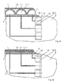
- FIGS. 43 and 44 show an enlarged section X of FIG Fig.41 and Fig.42.
- Fig. 43 shows the medium in the liquid state
- Fig.44 shows the medium in the vapor state.
- Spacer 4.4 form a filled with the medium cavity 4.9 between the inner 4th and the outer shell 1.
- the spacers 4.4 are part of the inner shell 4 (Fig.43 and Fig.44) or the outer shell 1 (not shown). is If the medium is in the liquid state (FIG. 43), the cavity is 4.9 completely filled with the liquid medium and the insulating effect is lower than when the medium is in the vapor state (Fig. 44).
- Another variant K of the invention has the hot water bottle as the Variants E, F, G, cavities 11.1 which outside the inner shell. 4 or cavities 4.9 are integrated into the inner shell 4.
- everyone Cavity is connected via a line to a reservoir, or the Reservoir connects directly to the cavity and is via an opening with spatially connected to the cavity, i. the reservoir forms with the Cavity a common closed cavity.
- Reservoir consists of a rigid material, for example Hard plastic, it has a nearly constant at all operating temperatures Volume.
- the outer wall of the reservoir has contact with the water 3, with the inner shell 4 of the hot water bottle is filled. At normal Room temperature of about 20 ° C, the reservoir is fully filled with water and the cavities 11.1 and 4.9 are empty and contracted.
- Another variant L of the invention has the hot water bottle identical cavities 11.1 and 4.9 as the variant E, F, G, H, I and a Cylinder 13 with a piston 14 (Fig.19 and 20).
- This piston 14 is over Lever, or rods 18 connected to other pistons 15 in cylinders 16.
- Each of these cylinders 16 is via a conduit 17 each having a cavity 11.1 connected.
- the cavity 16.1 on the piston side of the cylinder 16 is filled with air or gas.
- the cavity 13.1 on one side of the piston 14 is provided with a Medium filled, which is liquid at normal room temperature of about 20 ° C.
- variant AL according to the invention of the hot water bottle has the same Elements such as variant L. However, this is a Cool bottle.
- the variant continues to differ by the cylinder 14. In it is located in this variant, the medium whose boiling point between 0 ° C and 30 ° C, preferably between 5 ° C and 15 ° C, im Cavity 13.2 on the rod side of the cylinder 14 (Fig.46).
- This Cavity 13.2 by means of the rod seal of the cylinder 13, after closed tightly on the outside. 46 shows the cooling bottle in a state in which the temperature of the water 3 and the medium in the cavity 13.2 below the boiling temperature of the medium and thus the medium is liquid.
- the cooling bottle warms up over the temperature of the Boiling point of the medium, it evaporates, expands, increases the cavity 13.2 moves the piston 14 to the right (Fig.47) and moves thus above the rods 18 and the piston 15 to the right, increases the Cavity 16.1, thus reduces the cavity 11.1 and thus reduces the Insulating effect of the cooling bottle.
- variant M works according to the same principle of operation as variant L.
- Each of the cylinders 16 with piston 15 forms here, as in variant L, on the piston side a cavity 16.1, via lines 17, each with one of the cavities 11.1 or 4.9 is connected (Fig.44).
- Fig.44 there are no rods 18 and no cylinder 13 with piston 14 and here are the cylinder 16 on the closed on the other side of the piston and form a closed there Cavity 16.2.
- This cavity is as in variant L with a medium filled at normal room temperature of about 20 ° C is liquid and its boiling point between 30 ° C and 100 ° C, preferably between 35 ° C and 80 ° C, lies.
- Fig. 44 shows the medium at a temperature above the boiling point of the medium lies. In Fig. 45, the medium is liquid.
- variant N works on the same principle as the variant L. It has the same cavities 11.1 and 4.9, which are connected via lines 17 with cylinders 16 and 16 with the piston side 16.1 of the cylinder a common Form cavity, which is filled with the medium air, water, gas or oil.
- the piston 15 can be moved by the operator by hand.
- the piston rods protrude either out of the heat surface, or the cylinder 16 with piston 15 are mounted entirely outside the hot water bottle, or the piston 15 are movable via actuators, which are accessible to the operator.
- the actuators are interconnected so that all the pistons 15 are simultaneously moved by moving one actuator.
- variant Y according to the invention of the hot water bottle works following the same principles of operation as variants M and N. Instead several cavities 11.1 and 4.9, but this variant has only via a cavity 4.9 as in variant Z. This cavity is over a Line 17 is connected to a cylinder 16.
- variant Y with the same functional principle as variant N, for the one cylinder only one Actuator needed.
- variant O works according to the same functional principle as the variants E, F, G, K, L, M, or N, but it dispenses with an outer shell 1, or as variant J on a second outer shell 1.1. This results in comparison to the other variants with an outer shell a cost savings. The insulation is through overall lower than the other variants.
- the following inventive variants P and Q of the hot water bottle have an inner shell 4 and an outer shell 1.
- the outer shell 1 is permeable to air or has holes.
- the inner shell 4 is waterproof and in use (when the closure cover of the inner shell is closed) forms a closed volume.
- the inner shell 4 is filled with hot water 3 (about 60-100 ° C) and closed the cap. In this state, the cavity 12 is largest between inner shell 4 and outer shell 1 ( Figure 21). Cools the water 3 to about 30 ° C, so the volume of water decreases.
- the reduction in volume deforms the inner shell 4 such that the cavity 12 between inner shell 4 and outer shell 1 decreases (FIG. 22). In this case, air flows out of the cavity 12, through the outer shell 1, to the outside.
- the inner shell 4 has a bottom 4.2 and several reservoirs 4.3, which have an opening 4.8 to the water 3.
- the volume of water in the inner shell 4 is greatest and the water 3 completely fills the reservoirs 4.3, erects them and thereby the cavity 12, between inner Shell 4 and outer shell 1, in this state, the largest (Fig. 21). If the water 3 cools to about 30 ° C, the volume of water decreases and draws the reservoirs 4.3 such that the cavity 12 between the inner shell 4 and the outer shell 1 decreases (FIG. 22).
- the inner shell 4 has plate-shaped elements 4.5 on which spacers 4. 4 are seated. If the water is hot (about 60 ° C), the volume of water fills the inner shell 4 so that deform the plate-shaped elements 4.5, thus the spacers 4.4 push the outer shell 1 of the inner shell 4 and the cavity 12, between inner shell 4 and outer shell 1, enlarge (FIG. 23). If the water 3 cools to about 30 ° C., the volume of water decreases and the dish-shaped elements 4.5 with the spacers 4.4 draw inwards, so that the cavity 12 between inner casing 4 and outer casing 1 decreases (FIG. 24).
- the plate-shaped elements must be more elastic than the rest of the inner shell 4.
- This rest of the inner shell 4 is therefore, for example by ropes 4.6 , which span the entire size of the hot water bottle (shown in dashed lines), stiffened. These ropes are made of material that is stiffer than the inner shell.
- the inner shell 4 at the locations outside of the plate-shaped elements stiffened by reinforcements 4.7 (shown in phantom).
- the inventive variant R of the hot water bottle corresponds to the variant Q, but the elements of the inner shell 4 which deform in a change in volume of the water not plate-shaped, but there are elongated V-shaped elements 4.5 (Fig. 23 + 24) or rings. If they are rings, they extend over the entire circumference of the hot water bottle.
- the spacers 4.4 and the reinforcements 4.7 are also elongated elements or rings that extend over the circumference of the hot water bottle.
- the inventive variant S of a cooling bottle also works after the principle (as variant Q) that the volume change of the water 3 in the inner shell 4, the inner shell 4 deformed, but it works as a cooling bottle, so in reverse as a hot water bottle.
- the water is 3 at room temperature in the cooling bottle filled and this is closed, while the inner shell 4 applies to the outer shell 1 at (Fig.48).
- the cooling bottle is cooled in the refrigerator, while decreases the volume of water filling 3, so that the inner Case 4 deformed in the state of loud V-pofiles lined up (Fig.49).
- the enlarged cavity 12 increases the insulating effect.
- the inventive variant T of a cooling bottle works according to the same principle as the variant S, however, in this variant is the outer shell 1 more stretchable than in variant S. warms up the Water filling and thus increases the volume of water 3, so this causes an extension of the inner shell 4 (Fig.50), at the same time Elongation of the outer shell 1. As a result, the inner shell 4 applies to the outer shell 1 and the reduced cavity 12 reduces the Insulating effect. If, however, the closed cooling bottle and thus even the water 3 cooled again in the refrigerator, it reduces Volume of the water 3 and then deforms the inner shell 4 and thus increases the cavity 12 (Fig.51).
- U of the hot water bottle has the inner Cover 4 a bottom 4.2 and several reservoirs 4.3, which has an opening 4.8 to have water 3.
- the inner shell 4 and the outer shell 1 are over Spacer 20 connected.
- hot water is 3 (about 60 ° C), in the inner shell 4 filled the hot water bottle and this with a closure locked.
- the reservoirs 4.3 are completely filled and erected together with the spacers (Fig.29).
- the water cools down 3, so it reduces its volume, withdraws from the reservoirs 4.3 back and fold them together.
- the outer shell 1 moves to the right and works thereby the spacers to the right (Fig.30). Consequently reduces the cavity 12 and thus reduces its Insulating effect.
- Variant X heats or cools the heating or cooling bottle by means of electrical elements. If it is a hot water bottle, then it works like the variants E, F, F1, F2, H, I, L, M, N, P, Q, V, U, Y, Z, but the water 3 in this case heated a heating coil, which is located within the hot water bottle directly in the water 3, or by heating wire which is woven into the inner shell 4 and thus also has contact with the water 3. For heating, the heating coil or the heating wire is connected to a power supply. If the water has reached the desired temperature, then the power supply can be interrupted and it is independent of this and it can cause in the hot water bottle no short circuit and no electrosmog. If it is a cooling bottle it works like variants S or T, but inside the cooling bottle there is an electric cooling element which cools the water 3 in the inner shell 4.
- the space between the inner shell 4 and the outer shell 1 is filled with a gel 21 (FIGS. 37 and 38).
- the gel 21 contains the same medium as in variant E, which is liquid at room temperature of about 20 ° C and at a temperature higher than the boiling point of the medium (preferably between 40 ° C and 80 ° C) becomes gaseous.
- the medium is located between the gel 21 and the outer shell 1 (82), or it is located inside the gel 21 (B1). In the case of B1, in the production of the hot water bottle, the medium is injected into the gel 21, or mixed in mechanically.
- the medium is dropped by means of pipettes onto the gel surface, or it is sprayed on by means of spray nozzles.
- hot water 3 with a temperature which is higher than the boiling point of the medium 22, filled in the inner shell 4 of the hot water bottle, so also heats the gel 21 and the medium 22 evaporates and thus increases its volume and thus the insulating effect of the Hot water bottle (Fig.38).
- the outer shell 1 is so elastic that it can adapt to the increase in volume of the medium 22. If the water 3 cools down, the medium 22 also cools down. If the temperature of the medium 22 drops below its boiling point, this becomes liquid again, reduces its volume and thus reduces the insulating effect of the hot water bottle (FIG.
- the hot water bottle is heated in the microwave.
- the inner shell 4 and the water filling 3 is dispensed with.
- the filling of the outer shell 1 consists entirely of gel 21 and the medium 22.
- the hot water bottle is heated in the microwave.
- the gel 21 also heats up and the medium 22 evaporates, thus increasing its volume. This increase in volume pushes, as in variant Q, the spacers 4.4 outwards and thereby increases the cavity 12, between the inner shell 4 and the outer shell 1 (FIG. 39).
- the medium 22 When the water 3 cools to a temperature below the boiling point of the medium (about 30 ° C.), the medium 22 also cools, condenses, reduces its volume and thus draws the dish-shaped elements 4.5 inwards with the spacers 4.4, so that the cavity 12 between the inner shell 4 and the outer shell 1 decreases (FIG. 40).
- the second inner shell 6 and the water filling 3 are dispensed with.
- the filling of the inner shell 4 consists entirely of gel 21 and the medium 22.
- the hot water bottle is heated in the microwave.
- the variant W 1 according to the invention is like the variants P, Q, S, T, or U built up.
- gel is in the inner shell 4.
- a medium 22 which is liquid at room temperature of about 20 ° C and at a temperature higher than the boiling point of the medium (preferably between 40 ° C and 80 ° C) becomes gaseous.
- the hot water bottle is heated in the microwave. Is rising like that Temperature of the medium 22 above the boiling temperature of the medium 22, so the medium 22 evaporates and thus increases its volume.
- the variant XA according to the invention is a cooling bottle.
- the inner shell 4 and the outer shell 1 are connected to partitions 2, whereby the cavities 5 form.
- On the inner shell 4 closed hollow body 11 are glued.
- a waterproof film 19 is glued, which is also glued between the compound of the partitions 2 and the outer shell 1.
- the cavity 11.1 of the hollow body 11 is filled with a medium whose boiling point is between 0 ° C and 30 ° C, preferably between 5 ° C and 15 ° C.
- the inner shell 4 of the cooling bottle with a liquid, preferably water 3, filled and sealed.
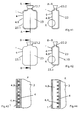
- the medium in the cavity 11.1 is also heated and becomes gaseous, thus expanding and expands the hollow body 11 to a nearly circular shape (Fig. 1).
- the film 19 is pressed against the outer shell 1 and the cavity 5 is increased.
- water 3 flows through the holes 4.1 from the inner shell 4 into the cavity 5.
- the cooling bottle is cooled in the refrigerator to a temperature of about 3 ° C. This temperature is below the boiling point of the medium in the cavity 11.1.
- the medium becomes liquid, reduces its volume and pulls the cavity 11.1 together (Fig.2).
- the film 19 is pulled away from the outer shell 1 and thus the cavity 12 is increased, which fills with air from outside the cooling bottle, which can penetrate through the air-permeable outer shell 1.
- the excess water 3 from the cavity 5 flows through the holes 4.1 back into the interior of the cooling bottle.
- the insulation of the cooling bottle is greatest by the air in the cavity 12.
- the cooling bottle is heated to a temperature which is above the boiling point of the medium, it becomes gaseous, thus expanding and inflating the hollow body 11 to an almost circular shape (FIG. 1).
- the film 19 is pressed against the outer shell 1 and the cavity 5 is enlarged and the cavity 12 is reduced (FIG. 1).
- water 3 flows into the cavity 5 through the holes 4.1 from the inner shell 4 and the air of the cavity 12 escapes through the air-permeable outer shell 1.
- the air-filled cavity 12 thus no longer exists, it also has no insulating effect.
Landscapes
- Health & Medical Sciences (AREA)
- Vascular Medicine (AREA)
- Engineering & Computer Science (AREA)
- Biomedical Technology (AREA)
- Heart & Thoracic Surgery (AREA)
- Life Sciences & Earth Sciences (AREA)
- Animal Behavior & Ethology (AREA)
- General Health & Medical Sciences (AREA)
- Public Health (AREA)
- Veterinary Medicine (AREA)
- Thermal Sciences (AREA)
- Physics & Mathematics (AREA)
- Thermotherapy And Cooling Therapy Devices (AREA)
- Thermally Insulated Containers For Foods (AREA)
Abstract
Description
Die Wärmflaschen können auch dazu benutzt werden, um zu kühlen. Diese nennt man dann auch Kühlflaschen. Dazu wird die mit einer Flüssigkeit oder Gel gefüllte Wärmflasche vor der Anwendung im Gefrierschrank heruntergekühlt, oder in sie wird kalte Flüssigkeit, oder Eiswürfel eingefüllt. Dabei tritt das gleiche Problem auf, wie bei der wärmenden Wärmflasche, nur in diesem Fall auf die Kälte bezogen. Die abgegebene Kaltemenge bleibt nicht konstant. Zu Anfang der Anwendung ist die Wärmflasche für den Benutzer zu kalt und später ist sie nicht mehr kühlend genug.
Je nach Schaumstoffeigenschaften kann der Schaumstoff, während er sich mit Wasser 3 füllt, pro Zeiteinheit gleichmäßig viel Wasser 3 aufnehmen, oder er verändert seine Wasseraufnahmefähigkeit pro Zeiteinheit mit der sich ändernden Temperatur des Schaumstoffes. Die Temperatur des Schaumstoffes 24 ändert sich mit der Temperatur des Wassers 3, da das Wasser 3 an den Schaumstoff 24 angrenzt und in den Schaumstoff 24 einfließt. Hat der Schaumstoff 24 eine, mit einer Temperaturänderung einhergehende, veränderliche Wasseraufnahmefähigkeit, so ist dafür beispielsweise der sehr hohe Wärmeausdehnungskoeffizient des Schaumstoffes 24 verantwortlich, der bei einer Temperaturerhöhung die Poren des Schaumstoffes zunehmend verschließt und bei einer Temperaturabnahme des Schaumstoffes 24 die Poren zunehmend öffnet.
Fig. 10 zeigt einen Ausschnitt der Wärmflasche beim Befüllen der Wärmflasche mit Wasser 3. Dabei zeigt in dieser Darstellung die Richtung 7 nach oben zum Wärmflaschenverschluss durch den das Wasser von außen eingefüllt wird. Beim Befüllen steigt der Wasserspiegel 3.1 an und drückt dadurch die zweite innere Hülle 6 an die innere Hülle 4 an. Das Wasser fließt nur im Bereich Löcher 4.1 durch die zweite innere Hülle 6. Indem die innere Hülle 4 und die zweite innere Hülle 6 eng aneinander anliegen sind die Löcher 6.1 der zweiten inneren Hülle 6 verschlossen und das Wasser kann nur im Bereich der Löcher 4.1 die wasserdurchlässige zweite innere Hülle 6 durchdringen. Dies bedeutet das die Fläche der zweiten inneren Hülle 6, die vom Wasser durchdrungen wird sehr klein ist. Sie entspricht der Summe der addierten Flächen der Löcher 4.1, der inneren Hülle 4, die unter dem Wasserspiegel liegen, Entsprechend langsam füllen sie die Hohlräume 5 mit Wasser.
Zum Entleeren der Wärmflasche wird der Wärmflaschenverschluss geöffnet und die Wärmflasche gedreht, so dass der Verschluss nach unten zeigt. Dies ist in Fig. 11 dargestellt. 7 zeigt hier nach unten in Richtung zum Wärmflaschenverschluss. Sofort nachdem das Wasser 3 aus der zweiten inneren Hülle 6 abgeflossen ist, strömt das Wasser aus den Hohlräumen 5 durch die Löcher 4.1 der inneren Hülle 4 und drückt die zweite innere Hülle 6 von der inneren Hülle 4 weg. Das Wasser flutet den entstandenen Hohlraum 10 zwischen inneren Hülle 4 und der zweiten inneren Hülle 6 und fließt ungehindert durch die Löcher 6.1 der zweiten inneren Hülle 6 ab. Da das Wasser aus den Hohlräumen 5 komplett durch die Löcher 4.1 und 6.1 abfließen kann und nicht die zweite innere Hülle 6 an den Flächen der Löcher 4.1 der inneren Hülle 4 durchdringen muss, vollzieht sich das Abfließen viel schneller, als das Füllen der Hohlräume 5, nach dem Befüllen der Wärmflasche. Das Abfließen wird unter einer Minute dauern, das Füllen der Hohlräume 5 dagegen mehrere Stunden.
Alternativ ist die innere Hülle 4 wasserdurchlässig und hat die gleichen Löcher 4.1. In dieser Ausführung vollzieht sich das Füllen Hohlräume 5 mit Wasser schneller, aber dennoch langsamer als das Entleeren des Wassers.
Eine weitere erfindungsgemäße Variante entspricht vom Aufbau her der vorherigen Variante D, jedoch besitzt hier die innere Hülle 4 die Löcher 4.1 und ist aus wasserdichtem Material und die zweite innere Hülle 6 besitzt keine Löcher und ist wasserdurchlässig.
In Variante F1 sind die Hohlräume 4.9 übereinander angeordnet. In Fig.31 ist das Medium dampfförmig und in Fig.32 flüssig.
In Variante F2 sind die Hohlräume 4.9 nebeneinander angeordnet. In Fig.33 ist das Medium dampfförmig und in Fig.34 flüssig. Alternativ gibt es keine äußere Hülle 1 A1, oder die innere Hülle 4 ist von einer isolierenden äußeren Hülle 1 ganz A2, oder teilweise A3 überzogen.
Alternativ zum manuellen Verschieben der Kolben 15 werden diese automatisch über einen Temperaturregler bewegt. Dieser funktioniert wie ein Thermostat eines Heizkörpers. Es ist vom Wasser 3 der Wärmflasche umgeben und arbeitet mit ein Bimetall das sich bei Temperaturänderung verformt. Ändert sich die Temperatur des Wassers 3, so bewegt das Thermostat die Kolben 15 in den Zylindern 16 und ändert somit das Volumen der Hohlräume 11.1 bzw. 4.9 und damit auch die Isolierwirkung. Das Bimetall im Thermostat ist dabei so angeordnet, dass es bei der Kühlflasche mit zunehmender Erwärmung des Wassers 3 die Isolierung verringert. Bei der Wärmflasche hingegen ist es so angeordnet, dass es bei zunehmender Abkühlung des Wassers 3 die Isolierung verringert.
Bei der erfindungsgemäßen Variante P der Wärmflasche besitzt die innere Hülle 4 einen Boden 4.2 und mehrere Reservoire 4.3, die eine Öffnung 4.8 zum Wasser 3 haben. Nach der Befüllung der inneren Hülle 4 mit heißem Wasser 3 (60°C), ist das Wasservolumen in der innere Hülle 4 am größten und das Wasser 3 füllt die Reservoire 4.3 komplett aus, richtet diese auf und dadurch ist der Hohlraum 12, zwischen innerer Hülle 4 und äußerer Hülle 1, in diesem Zustand am größten (Fig. 21). Kühlt sich das Wasser 3 auf etwa 30°C ab, so verkleinert sich das Wasservolumen und zieht die Reservoire 4.3 derart zusammen, dass sich der Hohlraum 12 zwischen innerer Hülle 4 und äußerer Hülle 1 verkleinert (Fig. 22).
Bei der erfindungsgemäße Variante Q der Wärmflasche besitzt die innere Hülle 4 tellerförmige Elemente 4.5 auf denen Abstandhalter 4.4 sitzen. Ist das Wasser heiß (etwa 60°C), so füllt das Wasservolumen die innere Hülle 4 derart aus, dass sich die tellerförmigen Elemente 4.5 verformen, somit die Abstandshalter 4.4 die äußere Hülle 1 von der inneren Hülle 4 wegdrücken und den Hohlraum 12, zwischen innerer Hülle 4 und äußerer Hülle 1, vergrößern (Fig. 23). Kühlt sich das Wasser 3 auf etwa 30°C ab, so verkleinert sich das Wasservolumen und zieht die tellerförmigen Elemente 4.5 mit den Abstandhaltern 4.4 nach innen, so dass sich der Hohlraum 12 zwischen innerer Hülle 4 und äußerer Hülle 1 verkleinert (Fig. 24). Damit sich bei einer Volumenänderung des Wassers nicht die gesamte innere Hülle 4, sondern nur die tellerförmigen Elemente 4.5 verformen, müssen die tellerförmigen Elemente elastischer sein, als der Rest der inneren Hülle 4. Dieser Rest der inneren Hülle 4 wird deshalb, beispielsweise durch Seile 4.6, -die den ganzen Wärmflaschenumfang umspannen (gestrichelt dargestellt), versteift. Diese Seile bestehen aus Material das steifer ist als das der inneren Hülle. Alternativ wird die innere Hülle 4 an den Stellen, außerhalb der tellerförmigen Elementen, durch Verstärkungen 4.7 (gestrichelt dargestellt) versteift.
Die erfindungsgemäße Variante R der Wärmflasche entspricht der Variante Q, allerdings sind die Elemente der inneren Hülle 4 die sich bei einer Volumenänderung des Wassers verformen nicht tellerförmig, sondern es sind längliche V-förmige Elemente 4.5 (Fig. 23+24) oder Ringe. Sind es Ringe, so erstrecken sich diese über den gesamten Umfang der Wärmflasche. Die Abstandhalter 4.4 und die Verstärkungen 4.7 (gestrichelt dargestellt) sind ebenfalls längliche Elemente oder Ringe, die sich über den Umfang der Wärmflasche erstrecken.
Handelt es sich um eine Kühlflasche so funktioniert sie wie die Varianten S oder T, allerdings befindet sich innerhalb der Kühlflasche ein elektrisches Kühlelement, welches das Wasser 3 in der inneren Hülle 4 abkühlt.
Wird heißes Wasser 3 mit einer Temperatur, die höher als der Siedepunkt des Mediums 22 ist, in die innere Hülle 4 der Wärmflasche gefüllt, so erhitzt sich auch das Gel 21 und das Medium 22 verdampft und vergrößert somit sein Volumen und somit auch die Isolationswirkung der Wärmflasche (Fig.38). Dabei ist die äußere Hülle 1 so elastisch, dass sie sich an die Volumenvergrößerung des Mediums 22 anpassen kann. Kühlt sich das Wasser 3 ab, so kühlt sich auch das Medium 22 ab. Fällt die Temperatur des Mediums 22 unter seinen Siedepunkt, so wird dies wieder flüssig, verkleinert sein Volumen und verringert somit die Isolationswirkung der Wärmflasche (Fig.37). Alternativ befindet sich in der inneren Hülle statt Wasser 3 Gel. In dieser Ausführung wird die Wärmflasche in der Mikrowelle erhitzt. Bei einer anderen Alternative wird auf die innere Hülle 4 und die Wasserfüllung 3 verzichtet. In diesem Fall besteht die Füllung der äußeren Hülle 1 gänzlich aus Gel 21 und dem Medium 22. Bei dieser Ausführung wird die Wärmflasche in der Mikrowelle erhitzt.
Alternativ wird auf die zweite innere Hülle 6 und die Wasserfüllung 3 verzichtet. In diesem Fall besteht die Füllung der inneren Hülle 4 gänzlich aus Gel 21 und dem Medium 22. Bei dieser Alternative wird die Wärmflasche in der Mikrowelle erhitzt.
Zunächst wird die innere Hülle 4 der Kühlflasche mit einer Flüssigkeit, vorzugsweise Wasser 3, gefüllt und verschlossen. Indem das Wasser 3 wärmer ist, als der Siedepunkt des Mediums, wird das Medium im Hohlraum 11.1 ebenfalls erwärmt und wird gasförmig, dehnt sich somit aus und bläht den Hohlkörper 11 zu einer fast kreisrunden Form auf (Fig. 1). Dadurch wird die Folie 19 an die äußere Hülle 1 gedrückt und der Hohlraum 5 vergrößert. Dabei strömt in den Hohlraum 5 Wasser 3 durch die Löcher 4.1 aus der inneren Hülle 4 nach. Anschließend wird die Kühlflasche im Kühlschrank auf eine Temperatur von etwa 3°C abgekühlt. Diese Temperatur liegt unter dem Siedepunkt des Mediums im Hohlraum 11.1. Dadurch wird das Medium flüssig, verkleinert sein Volumen und zieht den Hohlraum 11.1 zusammen (Fig.2). Dadurch wird die Folie 19 von der äußeren Hülle 1 weggezogen und somit der Hohlraum 12 vergrößert, der sich mit Luft von außerhalb der Kühlflasche füllt, welches durch die luftdurchlässige äußere Hülle 1 eindringen kann. Das überschüssige Wasser 3 aus dem Hohlraum 5 fließt durch die Löcher 4.1 zurück ins innere der Kühlflasche. In diesem Zustand ist durch die Luft im Hohlraum 12 die Isolation der Kühlflasche am größten. Erwärmt sich die Kühlflasche auf eine Temperatur, die über dem Siedepunkt des Mediums liegt, so wird dieses gasförmig, dehnt sich somit aus und bläht den Hohlkörper 11 zu einer fast kreisrunden Form auf (Fig. 1). Dadurch wird die Folie 19 an die äußere Hülle 1 gedrückt und der Hohlraum 5 vergrößert und der Hohlraum 12 verkleinert (Fig.1). Dabei strömt in den Hohlraum 5 Wasser 3 durch die Löcher 4.1 aus der inneren Hülle 4 nach und die Luft des Hohlraums 12 entweicht durch die luftdurchlässige äußere Hülle 1. Indem der luftgefüllte Hohlraum 12 somit nicht mehr besteht, hat er auch keine isolierende Wirkung mehr.
- 1
- äußeren Hülle
- 1.1
- zweite äußere Hülle
- 2
- Trennwand
- 3
- Wasser
- 3.1
- Wasserspiegel
- 4
- innere Hülle
- 4.1
- Loch
- 4.2
- Boden
- 4.3
- Reservoir
- 4.4
- Abstandshalter
- 4.5
- Teller/V-Ring
- 4.6
- Seil
- 4.7
- Verstärkung
- 4.8
- Öffnung
- 4.9
- Hohlraum
- 4.10
- Hohlraum
- 5
- Hohlraum
- 6
- zweite innere Hülle
- 6.1
- Loch
- 7
- Richtung Wärmflaschenverschluss
- 8
- Richtung: weg von Wärmflaschenverschluss
- 9
- Luft
- 10
- Hohlraum
- 11
- Hohlkörper
- 11.1
- Hohlraum
- 12
- Hohlraum
- 13
- Zylinder
- 13.1
- Hohlraum
- 13.2
- Hohlraum
- 14
- Kolben
- 15
- Kolben
- 16
- Zylinder
- 16.1
- Hohlraum
- 16.2
- Hohlraum
- 17
- Leitung
- 18
- Stange
- 19
- Folie
- 20
- Abstandshalter
- 21
- Gel
- 22
- Medium
- 23
- Wärmflasche
- 23.1
- Rand
- 23.2
- Einfüllstutzen
- 24
- Schaumstoff
Claims (10)
- Wärmflasche oder Kühlflasche für Mensch oder Tier, dadurch gekennzeichnet, dass die Isolierwirkung der Wärmflasche mit zunehmender Abkühlung der Wärmflasche, oder mit zunehmender Erwärmung der Kühlflasche abnimmt, oder die lsollerwirkung manuell verändert werden kann.
- Wärmflasche nach Anspruch 1, dadurch gekennzeichnet, dass wenigstens eine innere Hülle 4 von Hohlräumen 5 umgeben ist und sich innerhalb der inneren Hülle 4 wenigstens eine zweite innere Hülle 6 befindet, in die eine Flüssigkeit, vorzugsweise Wasser, gefüllt wird.
- Wärmflasche nach Anspruch 1, dadurch gekennzeichnet, dass wenigstens ein Hohlraum 11.1 bzw. 4.9 bzw. 4.10, der sich im Randbereich der Wärmflasche befindet, mit wenigstens einem bei 20°C flüssigen Medium, vorzugsweise Alkohol, gefüllt ist, dass bei einer Temperatur zwischen 30°C und 100°C, vorzugsweise zwischen 40°C und 80°C, verdampft und dass die innere Hülle 4 mit einer Flüssigkeit, vorzugsweise Wasser 3, oder mit einem Gel, oder mit Granulat, oder mit Körnern gefüllt ist.
- Wärmflasche nach Anspruch 1, dadurch gekennzeichnet, dass wenigstens ein Hohlraum 11.1, der sich im Randbereich der Wärmflasche befindet, mit einem Reservoir verbunden ist, dass über den Temperaturbereich von 10 bis 100°C ein nahezu konstantes Volumen hat. Das Reservoir mit wenigstens einem Medium, vorzugsweise Wasser, gefüllt ist, dass bei Erwärmung sein Volumen stärker vergrößert, als das Volumen des Reservoirs und dass die innere Hülle 4 mit einer Flüssigkeit, vorzugsweise Wasser 3, oder mit einem Gel, oder mit Granulat, oder mit Körnern gefüllt ist.
- Wärmflasche nach Anspruch 1, dadurch gekennzeichnet, dass die äußeren Hülle 1 mit einem Gel 21 gefüllt ist, indem sich wenigstens ein bei 20°C flüssiges Medium 22, vorzugsweise Alkohol, befindet, dass bei einer Temperatur zwischen 30°C und 100°C, vorzugsweise zwischen 40°C und 80°C, verdampft.
- Wärm- oder Kühlflasche nach Anspruch 1, dadurch gekennzeichnet, dass wenigstens eine flüssigkeitsdurchlässige innere Hülle 4 mit wenigstens einer flüssigkeitsdichten äußeren Hülle 1, wenigstens einen Hohlraum 5 bildet und dass die innere Hülle 4 mit einer Flüssigkeit, vorzugsweise Wasser 3, gefüllt wird.
- Kühlflasche nach Anspruch 1, dadurch gekennzeichnet, dass wenigstens ein Hohlkörper mit einem Medium gefüllt ist, dessen Siedepunkt zwischen 0°C und 30°C, vorzugsweise zwischen 5° C und 15°C, liegt und der eine Folie 19 bewegt, die durch diese Bewegung einen Hohlraum 12 vergrößert oder verkleinert.
- Wärm- oder Kühlflasche nach Anspruch 1, dadurch gekennzeichnet, dass sich in der flüssigkeitsdichten äußeren Hülle 1 ein flüssigkeitsdurchlässiger Schaumstoff 24 befindet und dass der Schaumstoff 24 mit einer Flüssigkeit, vorzugsweise Wasser 3, gefüllt wird.
- Verfahren zum Wärmen oder Kühlen von für Mensch oder Tier mit einer Wärmflasche oder Kühlflasche, dadurch gekennzeichnet, dass die Isolierwirkung der Wärmflasche mit zunehmender Abkühlung der Wärmflasche, oder mit zunehmender Erwärmung der Kühlflasche abnimmt, oder die Isolierwirkung manuell verändert werden kann.
- Verfahren zum Wärmen mit einer Wärmflasche nach Anspruch 9, dadurch gekennzeichnet, dass wenigstens ein Hohlraum 11.1 bzw. 4.9, der sich im Randbereich der Wärmflasche befindet und mit wenigstens einem Zylinder 16 einen abgeschlossenen Hohlraum 16.1 bildet und der Kolben 15 des Zylinders 16 die Füllung dieser Hohlräume aus, vorzugsweise Luft, oder Gas, oder Öl, oder Wasser, zwischen den Hohlräumen 11.1 bzw. 4.9 und 16.1 verändert und der Kolben 15 des Zylinders 16 manuell, oder über ein Thermostat, oder über die Volumenänderung eines Mediums bewegt wird und das Medium, vorzugsweise Alkohol ist und bei 20°C flüssig ist und dass das Medium bei einer Temperatur zwischen 30°C und 100°C, vorzugsweise zwischen 35°C und 80°C, verdampft und dass das Medium oder das Thermostat von der Füllung der inneren Hülle 4 erwärmt wird und dass die Füllung der inneren Hülle 4 aus Gel, oder Körnern, oder Granulat, oder Flüssigkeit, vorzugsweise Wasser 3, besteht.
Applications Claiming Priority (4)
| Application Number | Priority Date | Filing Date | Title |
|---|---|---|---|
| DE102004014324 | 2004-03-22 | ||
| DE102004014324 | 2004-03-22 | ||
| DE102004041835 | 2004-08-27 | ||
| DE102004041835A DE102004041835A1 (de) | 2004-03-22 | 2004-08-27 | Wärm- oder Kühlflasche mit Isolierschicht |
Publications (1)
| Publication Number | Publication Date |
|---|---|
| EP1579830A1 true EP1579830A1 (de) | 2005-09-28 |
Family
ID=34862932
Family Applications (1)
| Application Number | Title | Priority Date | Filing Date |
|---|---|---|---|
| EP05006320A Withdrawn EP1579830A1 (de) | 2004-03-22 | 2005-03-22 | Wärm- oder Kühlflasche mit Isolierschicht |
Country Status (2)
| Country | Link |
|---|---|
| EP (1) | EP1579830A1 (de) |
| DE (1) | DE102004041835A1 (de) |
Cited By (9)
| Publication number | Priority date | Publication date | Assignee | Title |
|---|---|---|---|---|
| WO2008040533A1 (de) * | 2006-10-04 | 2008-04-10 | Emcools-Emergency Medical Cooling Systems Ag | Vorrichtung zum temperieren des körpers eines patienten |
| EP2481311A3 (de) * | 2011-01-28 | 2012-10-10 | W.L. Gore & Associates GmbH | Laminatstruktur mit adaptiver Wärmeisolierung |
| WO2014019613A1 (en) * | 2012-07-31 | 2014-02-06 | W. L. Gore & Associates Gmbh | Envelope for a laminar structure providing adaptive thermal insulation |
| WO2014019611A1 (en) * | 2012-07-31 | 2014-02-06 | W. L. Gore & Associates Gmbh | Envelope for a laminar structure providing adaptive thermal insulation |
| WO2014019612A1 (en) * | 2012-07-31 | 2014-02-06 | W. L. Gore & Associates Gmbh | Combination of an envelope for a laminar structure providing adaptive thermal insulation and a heat protection shield |
| RU2546483C2 (ru) * | 2011-01-28 | 2015-04-10 | В.Л. Гор Унд Ассошиэйтс Гмбх | Слоистая структура, обеспечивающая адаптивную тепловую изоляцию |
| EP2667738B1 (de) * | 2011-01-28 | 2016-05-25 | W.L. Gore & Associates GmbH | Schichtverbund mit adaptiver wärmedämmung |
| US9927061B2 (en) | 2012-07-27 | 2018-03-27 | W. L. Gore & Associates Gmbh | Envelope for a laminar structure providing adaptive thermal insulation |
| EP2667739B1 (de) * | 2011-01-28 | 2018-08-22 | W.L. Gore & Associates GmbH | Schichtverbund mit adaptiver wärmedämmung |
Citations (2)
| Publication number | Priority date | Publication date | Assignee | Title |
|---|---|---|---|---|
| CH281706A (de) | 1950-04-14 | 1952-03-31 | Kissling Arnold | Wärmeflasche. |
| GB1359792A (en) | 1971-07-06 | 1974-07-10 | Smith E C | Heating and warming appliances such as hot water bottles |
Family Cites Families (4)
| Publication number | Priority date | Publication date | Assignee | Title |
|---|---|---|---|---|
| US2387258A (en) * | 1941-05-16 | 1945-10-23 | Hague Alfred | Thermal applicator |
| DE2115392C3 (de) * | 1971-03-30 | 1974-07-11 | Chattanooga Pharmacal Co., Chattanooga, Tenn. (V.St.A.) | Packen zur Anwendung von therapeutischer feuchter Wärme |
| DE8504306U1 (de) * | 1985-02-15 | 1986-06-12 | Weise-Richter, Helga, 8125 Huglfing | Wärmvorrichtung, insbesondere Wärmflasche |
| DE29808921U1 (de) * | 1998-05-18 | 1998-07-30 | Tüshaus, Joseph J., 46342 Velen | Wärme- oder Kühlvorrichtung für medizinische oder therapeutische Heilbehandlung |
-
2004
- 2004-08-27 DE DE102004041835A patent/DE102004041835A1/de not_active Withdrawn
-
2005
- 2005-03-22 EP EP05006320A patent/EP1579830A1/de not_active Withdrawn
Patent Citations (2)
| Publication number | Priority date | Publication date | Assignee | Title |
|---|---|---|---|---|
| CH281706A (de) | 1950-04-14 | 1952-03-31 | Kissling Arnold | Wärmeflasche. |
| GB1359792A (en) | 1971-07-06 | 1974-07-10 | Smith E C | Heating and warming appliances such as hot water bottles |
Cited By (20)
| Publication number | Priority date | Publication date | Assignee | Title |
|---|---|---|---|---|
| WO2008040533A1 (de) * | 2006-10-04 | 2008-04-10 | Emcools-Emergency Medical Cooling Systems Ag | Vorrichtung zum temperieren des körpers eines patienten |
| EP2667738B1 (de) * | 2011-01-28 | 2016-05-25 | W.L. Gore & Associates GmbH | Schichtverbund mit adaptiver wärmedämmung |
| EP2481311A3 (de) * | 2011-01-28 | 2012-10-10 | W.L. Gore & Associates GmbH | Laminatstruktur mit adaptiver Wärmeisolierung |
| EP2667739B1 (de) * | 2011-01-28 | 2018-08-22 | W.L. Gore & Associates GmbH | Schichtverbund mit adaptiver wärmedämmung |
| US9968808B2 (en) | 2011-01-28 | 2018-05-15 | W. L. Gore & Associates Gmbh | Laminar structure providing adaptive thermal insulation |
| EP2667740B1 (de) * | 2011-01-28 | 2017-11-15 | W.L. Gore & Associates GmbH | Schichtverbund mit adaptiver wärmedämmung |
| US9662516B2 (en) | 2011-01-28 | 2017-05-30 | W. L. Gore & Associates Gmbh | Laminar structure providing adaptive thermal insulation |
| RU2546483C2 (ru) * | 2011-01-28 | 2015-04-10 | В.Л. Гор Унд Ассошиэйтс Гмбх | Слоистая структура, обеспечивающая адаптивную тепловую изоляцию |
| AU2011357288B2 (en) * | 2011-01-28 | 2016-07-07 | W.L. Gore & Associates Gmbh | Laminar structure providing adaptive thermal insulation |
| US9927061B2 (en) | 2012-07-27 | 2018-03-27 | W. L. Gore & Associates Gmbh | Envelope for a laminar structure providing adaptive thermal insulation |
| CN104519763B (zh) * | 2012-07-31 | 2016-03-16 | W.L.戈尔有限公司 | 用于提供适应性隔热的层状结构的包封件 |
| CN104519763A (zh) * | 2012-07-31 | 2015-04-15 | W.L.戈尔有限公司 | 用于提供适应性隔热的层状结构的包封件 |
| CN104507340B (zh) * | 2012-07-31 | 2016-08-24 | W.L.戈尔有限公司 | 用于提供适应性隔热的层状结构的包封件 |
| CN104507341A (zh) * | 2012-07-31 | 2015-04-08 | W.L.戈尔有限公司 | 用于提供适应性隔热的层状结构的包封件和热保护罩的组合 |
| CN104507340A (zh) * | 2012-07-31 | 2015-04-08 | W.L.戈尔有限公司 | 用于提供适应性隔热的层状结构的包封件 |
| WO2014019612A1 (en) * | 2012-07-31 | 2014-02-06 | W. L. Gore & Associates Gmbh | Combination of an envelope for a laminar structure providing adaptive thermal insulation and a heat protection shield |
| WO2014019611A1 (en) * | 2012-07-31 | 2014-02-06 | W. L. Gore & Associates Gmbh | Envelope for a laminar structure providing adaptive thermal insulation |
| WO2014019613A1 (en) * | 2012-07-31 | 2014-02-06 | W. L. Gore & Associates Gmbh | Envelope for a laminar structure providing adaptive thermal insulation |
| US10085500B2 (en) | 2012-07-31 | 2018-10-02 | W. L. Gore & Associates Gmbh | Envelope for a laminar structure providing adaptive thermal insulation |
| US10092782B2 (en) | 2012-07-31 | 2018-10-09 | W.L. Gore & Associates Gmbh | Combination of an envelope for a laminar structure providing adaptive thermal insulation and a heat protection shield |
Also Published As
| Publication number | Publication date |
|---|---|
| DE102004041835A1 (de) | 2005-12-08 |
Similar Documents
| Publication | Publication Date | Title |
|---|---|---|
| DE69527313T2 (de) | Ballonkatheter zur hypertermiebehandlung | |
| EP3390785B1 (de) | Gleichdruckmehrkammerbehälter, thermodynamischer energiewandler und betriebsverfahren | |
| EP0781393B1 (de) | Sorptions-kühlaggregat | |
| EP3096723B1 (de) | Wärmeeinrichtung mit einem latentwärmespeichermittel | |
| DE2412631A1 (de) | Waermeuebergangsvorrichtung | |
| DE2713061A1 (de) | Warmwasserbereitungsanlage | |
| DE102004041835A1 (de) | Wärm- oder Kühlflasche mit Isolierschicht | |
| EP1308504B1 (de) | Inkubations-und Lagervorrichtung, insbesondere für Proben aus organischem Material | |
| DE102007010393A1 (de) | Wärmeübertrager, insbesondere Ölkühler | |
| WO2012065975A1 (de) | Wärmepumpe zur warmwasserbereitung | |
| DE102008054833A1 (de) | Vorrichtung zur Wiedergewinnung und Speicherung von Wärmeenergie aus einem Abwasser | |
| DE102015222731A1 (de) | Kältegerät mit Wasserzuführung | |
| DE202010013659U1 (de) | Kondensationsspeicher in einem Wärmepumpenkreislauf | |
| EP3505040B1 (de) | Geschirrspülmaschine, insbesondere haushaltsgeschirrspülmaschine | |
| EP3316268B1 (de) | Transformator mit beheiztem radiatorenglied | |
| DE3137290A1 (de) | "verfahren und vorrichtung zur waermespeicherung bei niedriger temperatur sowie deren anwendung" | |
| DE102016215387A1 (de) | Behältnis zur Ausbildung eines Wärmezwischenspeichers | |
| DE102012209112A1 (de) | Geschirrspülmaschine mit einem Wärmetauscher | |
| EP2221545A1 (de) | Backofen mit Latentwärmespeicher | |
| EP3675704A1 (de) | Haushaltsgeschirrspülmaschine mit tankanordnung | |
| WO2008028790A1 (de) | Kältegerät | |
| DE2817918A1 (de) | Waermebetriebene pumpe | |
| DE3040450A1 (de) | Vorrichtung zum volumenausgleich fuer einen warmwasserbereiter | |
| DE1917266A1 (de) | Verdampfungskuehlsystem | |
| WO2007025517A1 (de) | Vorrichtung und verfahren zum umwandeln von wärmeenergie in elektrische energie |
Legal Events
| Date | Code | Title | Description |
|---|---|---|---|
| PUAI | Public reference made under article 153(3) epc to a published international application that has entered the european phase |
Free format text: ORIGINAL CODE: 0009012 |
|
| AK | Designated contracting states |
Kind code of ref document: A1 Designated state(s): AT BE BG CH CY CZ DE DK EE ES FI FR GB GR HU IE IS IT LI LT LU MC NL PL PT RO SE SI SK TR |
|
| AX | Request for extension of the european patent |
Extension state: AL BA HR LV MK YU |
|
| 17P | Request for examination filed |
Effective date: 20060321 |
|
| AKX | Designation fees paid |
Designated state(s): AT BE BG CH CY CZ DE DK EE ES FI FR GB GR HU IE IS IT LI LT LU MC NL PL PT RO SE SI SK TR |
|
| RAP1 | Party data changed (applicant data changed or rights of an application transferred) |
Owner name: KRAISS, MARTIN |
|
| RIN1 | Information on inventor provided before grant (corrected) |
Inventor name: KRAISS, MARTIN |
|
| RAP1 | Party data changed (applicant data changed or rights of an application transferred) |
Owner name: KRAISS, MARTIN |
|
| RIN1 | Information on inventor provided before grant (corrected) |
Inventor name: KRAISS, MARTIN |
|
| 17Q | First examination report despatched |
Effective date: 20081106 |
|
| STAA | Information on the status of an ep patent application or granted ep patent |
Free format text: STATUS: THE APPLICATION IS DEEMED TO BE WITHDRAWN |
|
| 18D | Application deemed to be withdrawn |
Effective date: 20121002 |