EP1579235B1 - Verfahren zur bestimmung von azimut- undhöhenwinkeln durch verwendung eines einachsen-richtungfindungssystems - Google Patents
Verfahren zur bestimmung von azimut- undhöhenwinkeln durch verwendung eines einachsen-richtungfindungssystems Download PDFInfo
- Publication number
- EP1579235B1 EP1579235B1 EP03819050A EP03819050A EP1579235B1 EP 1579235 B1 EP1579235 B1 EP 1579235B1 EP 03819050 A EP03819050 A EP 03819050A EP 03819050 A EP03819050 A EP 03819050A EP 1579235 B1 EP1579235 B1 EP 1579235B1
- Authority
- EP
- European Patent Office
- Prior art keywords
- angle
- azimuth
- axis direction
- direction finding
- elevation
- Prior art date
- Legal status (The legal status is an assumption and is not a legal conclusion. Google has not performed a legal analysis and makes no representation as to the accuracy of the status listed.)
- Expired - Lifetime
Links
Images








Classifications
-
- G—PHYSICS
- G01—MEASURING; TESTING
- G01S—RADIO DIRECTION-FINDING; RADIO NAVIGATION; DETERMINING DISTANCE OR VELOCITY BY USE OF RADIO WAVES; LOCATING OR PRESENCE-DETECTING BY USE OF THE REFLECTION OR RERADIATION OF RADIO WAVES; ANALOGOUS ARRANGEMENTS USING OTHER WAVES
- G01S3/00—Direction-finders for determining the direction from which infrasonic, sonic, ultrasonic or electromagnetic waves, or particle emission, not having a directional significance, are being received
- G01S3/02—Direction-finders for determining the direction from which infrasonic, sonic, ultrasonic or electromagnetic waves, or particle emission, not having a directional significance, are being received using radio waves
- G01S3/14—Systems for determining direction or deviation from predetermined direction
- G01S3/46—Systems for determining direction or deviation from predetermined direction using antennas spaced apart and measuring phase or time difference between signals therefrom, i.e. path-difference systems
-
- G—PHYSICS
- G01—MEASURING; TESTING
- G01S—RADIO DIRECTION-FINDING; RADIO NAVIGATION; DETERMINING DISTANCE OR VELOCITY BY USE OF RADIO WAVES; LOCATING OR PRESENCE-DETECTING BY USE OF THE REFLECTION OR RERADIATION OF RADIO WAVES; ANALOGOUS ARRANGEMENTS USING OTHER WAVES
- G01S3/00—Direction-finders for determining the direction from which infrasonic, sonic, ultrasonic or electromagnetic waves, or particle emission, not having a directional significance, are being received
- G01S3/02—Direction-finders for determining the direction from which infrasonic, sonic, ultrasonic or electromagnetic waves, or particle emission, not having a directional significance, are being received using radio waves
- G01S3/023—Monitoring or calibrating
Definitions
- the present invention relates, in general, to a method of locating radiation emitters, and more specifically, to a method of determining azimuth and elevation angles of radiation signals from the emitter using a single-axis direction finding system.
- Airborne platforms such as airplanes and helicopters have been used for detecting the location/geolocation of emitters (e.g., a radiation emission source such as a radar transmitter).
- emitters e.g., a radiation emission source such as a radar transmitter.
- Such platforms are often equipped with Direction Finding (DF) systems that measure the angle-of-arrival (AOA) of radiation originating from the emitter.
- DF Direction Finding
- AOA angle-of-arrival
- the AOA is desirably determined using two orthogonally oriented measurement devices.
- These orthogonally oriented measurement devices are typically two distinct AOA measurement systems that measure respective orthogonal angles associated with the airborne platform to emitter direction with respect to the platform's frame of reference.
- the two orthogonal angles associated with the airborne platform to emitter direction are known as the azimuth angle and the elevation angle.
- the azimuth angle (az) is a horizontally measured angle associated with the direction of the airborne platform to the emitter.
- the azimuth angle is customarily measured with reference to magnetic north. Typically, the azimuth angle is greater than zero (az > 0) when measured from north to east, and the azimuth angle is less than zero (az ⁇ 0) when measured from north to west (i.e., -180° ⁇ az ⁇ +180°).
- the elevation angle (el) is a vertically measured angle associated with the emitter to airborne platform direction. The elevation angle is customarily measured from a horizontal plane.
- coordinate transformations are performed to convert the AOAs to an earth-referenced coordinate system so that the data can be used by geolocation algorithms and by other, off-board users.
- the measurement aircraft's 3-dimensional location and its angular orientation must be known. This data is usually available to a high degree of accuracy from the on-board GPS/INS (Global Positioning System / Inertial Navigation System) equipment.
- GPS/INS Global Positioning System / Inertial Navigation System
- This conventional method of measuring the azimuth and elevation AOAs suffers from various deficiencies.
- the cost of a two axis system may be significant.
- the two axis system may strain the antenna mounting and radar cross section limitations. As such, it is not always possible or desirable to install a full two-axes AOA measurement system on an aircraft.
- a single-axis AOA system may be employed.
- Single-axis systems are usually oriented to measure the emitter AOA with respect to the host aircraft's azimuth frame of reference.
- the elevation AOA is either assumed to be zero, or it is estimated based on a number of factors including the measurement aircraft's altitude. The estimate of the relative elevation angle is often somewhat inaccurate; this is particularly true when the aircraft is flying at high altitudes or when the emitter is located in an area that has significant terrain variations. If the elevation estimate is incorrect, the coordinate transformation can result in significant emitter azimuth AOA errors.
- a method of determining an azimuth and an elevation angle to a radiation emission source using a single-axis direction finding system of a pair of antennas includes sequentially over time receiving a plurality of radiation signals at the single-axis direction finding system.
- the plurality of radiation signals are emitted from the subject emitter, each of the plurality of radiation signals being received at one of a plurality of attitudes of the single-axis direction finding system.
- the method also includes measuring an angle of arrival of each of the plurality of radiation signals with respect to the single-axis direction finding system. Additionally, the method includes calculating an azimuth angle of each of the plurality of radiation signals with respect to the single-axis direction finding system using the respective measured angle of arrival.
- the method includes calculating a respective vector corresponding to each of the azimuth angles at different candidate elevation angles within a predetermined range. Further still, the method includes determining the elevation angle of the radiation emission source with respect to the single axis direction finding system by determining the intersection of the vectors.
- a method of determining both azimuth and elevation AOAs using a single-axis measurement system is provided. In an exemplary embodiment, this is achieved by using a series of azimuth angle-of-arrival measurements, while the measurement platform flies at various, known roll/pitch/yaw attitudes. Coordinate transformations are then performed on the series of measured azimuth AOAs, while assuming that the radiation emitter is at various elevation angles within a possible range of elevation angles. In this embodiment, the true elevation angle produces transformed AOA angles that converge in the direction of the emitter. For other relative elevation angles, the transformed AOAs do not all converge in the direction of the emitter.
- Airborne platforms are normally referred to in the inertial North-East-Down (NED) set of coordinate axes. That is, the direction pointing north, the down direction pointing to the center of the earth, and the east direction being perpendicular to both the north and down axes.
- NED North-East-Down
- FIG. 1 illustrates airborne platform 100 (e.g., an airplane) including an Angle Of Arrival (AOA) measurement system for receiving a radiation signal from a ground based emitter 102.
- AOA Angle Of Arrival
- This radiation signal is illustrated using wave vector 116 (vector K ) and range vector 114 (vector R ), from airborne platform 100 to emitter 102.
- N North/East/Down
- NED North/East/Down
- positive rotations are rotations in the clockwise direction when viewed toward the positive direction of the axis of rotation.
- ground based emitter 102 is located on the surface of earth in terms of latitude and longitude at position ⁇ e , ⁇ e ⁇ , while the aircraft's longitude and latitude is represented by ⁇ p , ⁇ p ⁇ .
- Figure 1 also illustrates three additional orthogonal vectors labeled X p (vector 110, tail-to-nose axis), Y p (vector 108, left wing to right wing axis) and Z p (vector 112) that define an alternate frame of reference 106 centered on airborne platform 100.
- Emitter 102 is shown extrapolated into frame of reference 106 (Rp x , Rp y , and Rp z ).
- Airborne platform attitude characteristics roll (identified with identifier 118), pitch (identified with identifier 120), and yaw (identified with identified 122) are also illustrated in Figure 1.
- Figure 1 also illustrates the azimuth (az) and elevation (el) angles from airborne platform 100 to radiation emitter 102 in the earth-referenced NED system.
- the direction cosines of the airborne platform axes relative to the NED axes are obtained via the aircraft navigation system (e.g., GPS/INS).
- Airborne platform attitude characteristics include yaw, pitch, roll, and heading.
- Yaw (y) may be defined as possible angular displacement between the tail-to-nose axis and actual course line.
- Pitch (p) may be defined as the angular displacement between the longitudinal axis of the airborne platform and the horizontal plane, where the sign ( ⁇ ) depends if the nose is up or down from the horizontal plane.
- Roll (r) may be defined as the angular displacement between the transverse axis of the airborne platform (e.g., left wing-to-right wing) and the horizontal, where the sign is (+) for left-wing-up, right-wing-down.
- Heading (h) may be defined as the horizontal direction in which an airborne platform is pointed with respect to a reference, the reference often being magnetic north. Heading is usually expressed in degrees, and is positive if clockwise from the reference.
- Figure 2a illustrates airborne platform 200, emitter 202, local inertial coordinate system 204 (earth referenced), and vector 216 (wave-vector K ), in relation to the World Coordinate System 228.
- Meridian line 220, Greenwich meridian 222, parallel latitude 224, and equator 226 are also illustrated in Figure 2a.
- Figure 2a also illustrates the airborne platform in terms of its associated coordinate system ⁇ X p ,Y p ,Z p ⁇ .
- a passive Direction Finding (DF) system on the airborne platform includes an azimuth-only interferometer that measures the azimuthal angle-of-arrival of the emitter's radiation (i.e., the wave-vector K ) with respect to the antenna axis fixed to the airborne platform.
- the wave-vector K the azimuthal angle-of-arrival of the emitter's radiation
- the angle of arrival is obtained via the measurement of the electrical phase difference at the interferometer elements.
- FIG 2b illustrates the orientation of an interferometer antenna system (interferometer 230) on an AOA measurement airborne platform 200 (aircraft).
- the system of coordinates 206 associated with airborne platform 200 is also shown.
- the interferometer antenna system 230 includes two antenna elements (1 and 2) separated by a distance “d” as indicated in Figure 2b .
- the Vector “n” (vector 232) is defined as a vector that is normal to the line that connects the two antenna elements, where "n” is at the midpoint between the two antenna elements.
- Angle “ ⁇ ” is the direction of vector "n” in the X p , Y p plane with respect to the tail-to-nose axis of airborne platform 200.
- Vector " n " in the X p ,Y p plane is directed from airborne platform 200 into quadrant 236 to the right of axis X p (as opposed to quadrant 234 to the left of axis Xp).
- the platform axes are the tail-to-nose axis X p , left-to-right wing axis Y p , and the direction Z p perpendicular to both the X p and Yp directions.
- the value associated with the scalar ⁇ (K•d) is independent of the coordinate system.
- K - ( 2 ⁇ ⁇ / ⁇ ) cos el ⁇ cos ( az ) , cos el ⁇ sin az , - sin el , where az is the azimuth angle with respect to North, and el is the relative elevation angle.
- the components K I in the platform system are obtained by means of successive coordinate rotations applied to the inertial components of the wave vector K.
- Figure 3 Exemplary successive coordinate rotations applied to the inertial components of the wave vector K are schematically illustrated in Figure 3 .
- These successive Euler rotations (R yaw ⁇ R pitch ⁇ R roll ) are utilized to achieve a generic coordinate transformation between the NED system and the platform system.
- Figure 3 visually shows Euler angle rotations used to transform angles from the earth-referenced inertial frame to the aircraft platform frame 302.
- the tilted ellipse 306 defined by axis X p , Y p , and Z p represents the aircraft platform 302 frame of reference, where p relates to the platform coordinate system.
- Rotations 308, 310, and 312 show the direction of successive Euler rotations, R yaw ⁇ R pitch ⁇ R roll , which are used to achieve a generic coordinate transformation.
- the first of the successive Euler rotations is rotation 312 (about the Z' axis), also known as R yaw , and is related to heading attitude of the airborne platform 302.
- Rotation 312 is positive in the North to East direction.
- the second of the successive Euler rotations is rotation 310 (about the Y' axis), also known as R pitch .
- Rotation 310 is positive in the nose up direction.
- the third of the successive Euler rotations is rotation 308 (about the X p axis), also known as R roll .
- Rotation 308 is positive in the right
- INS GPS aided Inertial Navigation System
- AHRS Altitude Heading Reference Set
- Figure 4 depists angular relationships expressed in Equation (1b).
- Heading (h) is the horizontal direction in which airborne platform 400 is pointed with respect to north.
- the antenna orientation, ⁇ is referenced to the platform tail-to-nose (Xp) direction, that is, along axis 408.
- the emitter's azimuth, az is referenced to north.
- the emitter AOA Angle-Of-Arrival
- quadrants 434 and 436 are quadrants 434 and 436, emitter 402, radiation vector 416, and left wing to right wing axis 410 (Yp).
- Equation (1b) explicitly shows that the measured phase ⁇ and the associated angle-of-arrival ⁇ contain extra contributions because of the relative elevation angle between platform and emitter (el), plus effects due to aircraft attitude [e.g., roll (r) and pitch (p)].
- CE coning error
- Figures 5 and 6 are useful in understanding the concept of CE.
- Figure 5 illustrates an exemplary relationship between the measured AOA (AOA c ) and the true AOA (AOA t ) as a function of emitter elevation. This exemplary diagram is useful for azimuth only DF systems.
- Figure 5 illustrates arm 530 (d) spanning between two antenna elements receiving radiation energy from emitter 502 along vector 516 (vector K ). The vector location of each of the antenna elements is different from one another (R 1 and R 2 ).
- Figure 5 also illustrates antenna axis 552 and equiphase cone axis 550, thereby defining azimuthal plane 556.
- the large circle 562 represents a cone shaped locus of AOA angles that all produce the same measured phase difference.
- the figure shows the difference between the measured angle-of-arrival (AOA c ) 560, and the true angle-of-arrival (AOA t ) 558, which is known as coning error, e.
- AOA t AOA m - Coning Error
- Expression (2a) also indicates that the CE is easy to correct if the relative elevation (el) is known or obtained by independent means.
- One object of the present invention is to describe a practical way of determining the relative elevation angle (el) for back correction of measured azimuthal angles-of-arrival.
- Figure 7a illustrates shows an emitter 702 on the ground along the heading direction of the aircraft 700.
- Figure 7b illustrates aircraft 700 with a flight path that is orthogonal to the azimuth direction of emitter 702.
- Both Figure 7a and 7b illustrate airborne platform 700 in terms of the Xp (tail to nose axis 708), Yp (left wing to right wing axis 710), and Zp (down axis 712) axes.
- Equation (1b) adopts a much simpler form.
- a positive roll left-wing-up and right-wing-down
- AOA 90° - a
- the INS system provides accurate values of the platform heading, pitch, and roll at fast repetition rates.
- the AOA measurement antenna installation angle ( ⁇ ) is also accurately known.
- the elevation angle (el) is not normally known.
- Figure 8a illustrates an engagement geometry between airborne platform 800 travelling at velocity V, and emitter 802, where the geometry includes Range (R), height h, and elevation angle (e).
- Figure 8b is a graphical representation of the elevation angle versus the range, in a geometry such as Figure 8a . More specifically, Figure 8b shows how the elevation angle between the airborne measurement platform and the ground emitter varies for typical engagement geometries. For moderate speeds and for typical platform-to-emitter ranges, the elevation angle does not change much over periods of 10-to-20 seconds, d(el) /dt - 0.03 deg/sec. As such, during the motion of the aircraft, a series of AOA measurements can be made at a substantially constant elevation.
- Figure 8b includes two curves.
- a goal is to determine the emitter's nominal azimuth angle, and its elevation angle, in an earth-referenced coordinate system by using the measured angle-of-arrival, which is determined in the platform-referenced coordinate system.
- the starting term of (2b) consists of the measured angle-of-arrival, ⁇ , corrected by the conventional coning error.
- the azimuth value obtained at the second iteration will be designated as follows: A ( r , p , h , el , ⁇ , ⁇ ) ⁇ az 2 ( r , p , h , el , ⁇ , ⁇ )
- the above iteration procedure (2b), to obtain the earth-referenced emitter's azimuth angle is based on a measured azimuthal angle-of-arrival ⁇ , and the airborne platform attitude (heading, pitch, roll) which is available from the aircraft INS/GPS system.
- the azimuth value is also a function of the relative elevation angle, which is initially unknown. Hence, a method for obtaining the elevation angle (el) is discussed next.
- the method of obtaining the elevation angle is based on the fact that the platform carrying the azimuth-only AOA measurement equipment can adopt different orientations while keeping the elevation relatively constant.
- the measured data, in conjunction with the INS data is sufficient for an approximate determination of the elevation angle (el).
- the accuracy of the elevation angle (el) will depend on the intrinsic accuracy of the AOA measurement system, the magnitude of the elevation, el, the relative geometry, the number of measurements taken, and to a lesser extent on the INS accuracy.
- Figure 9 shows how the angle to the emitter changes for a typical flight path.
- Angular measurements performed with platform headings h > h o are considered taken with roll attitudes r > 0 (left-wing-up), and p ⁇ 0 (nose-down).
- Angle-of-arrival ( ⁇ ) measurements taken when airborne platform headings h ⁇ h o will be assumed to be taken with roll attitudes r ⁇ 0 (right-wing-up), and pitch p ⁇ 0 (nose-down), or p > 0 (nose-up). Note that the angle-of-arrival should fall within the field -of-view of the antenna, that is ,
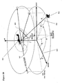
- FIG 10 illustrates a hovering aircraft 800 at two different headings.
- Aircraft 800 is shown in inertial coordinate system 804.
- Aircraft 800 includes an interferometer for receiving radiation from radiation vector 816 (vector K ) from emitter 802).
- Figure 10 pictorially shows the angular relationships associated with an AOA measurement system that is mounted on a hovering aircraft 800 (e.g., helicopter 800).
- the vectors labeled X1 and Y1 represent the aircraft tail to nose and left wing to right wing directions (respectively) for the first of two AOA measurements.
- the line labeled "1" (identified with identifier 860) represents the orientation of the interferometer for the first measurement.
- the vectors labeled X2 and Y2 represent the aircraft tail to nose and left wing to right wing directions (respectively) for the second AOA measurement.
- the line labeled "2" (identified with identifier 862) represents the orientation of the interferometer for the second measurement.
- the interferometer measurements are related to length of the interferometer (d), the wavelength of the emitter signal ( ⁇ ), the measured aoa (aoa 1 and aoa 2 (aoa is referenced to the interferometer axis)), the elevation angle (el), the azimuth to the emitter (az (azimuth is referenced to north)), the heading of the aircraft (h 1 and h 2 ) and the orientation of the interferometer axis relative to the aircraft ( ⁇ ), as provided in the two equations provided below.
- This equation provides the ability to obtain the relative elevation angle.
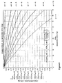
- Figure 11 illustrates curves of the resultant emitter azimuth for a series of angle-of-arrival measurements at different hovering aircraft headings, plotted versus a number of possible elevation angles.
- the vertical axis represents the nominal (or true) azimuth angle from a measurement aircraft to an emitter (the azimuth angle is referenced to north) and the horizontal axis represents the true elevation angle from the aircraft to the emitter.
- Figure 11 illustrates five curves, each curve representing a locus of azimuth/elevation points that correspond to an Angle Of Arrival (AOA) measurement taken from the hovering aircraft.
- AOA Angle Of Arrival
- the legend on the vertical axis shows aircraft orientation and AOA measurement values associated with each of the five curves.
- the other four curves show the locus of azimuth and elevation angles that would result in the other four AOA measurements shown in the vertical axis legend.
- the measurement error of the AOA has been purposely ignored.
- the measured angle of arrival ( ⁇ ) may contain implicit random errors, normally, characterized by a rms value ⁇ .
- the angle error, ⁇ mainly depends on arm imbalances, phase measurement errors ⁇ , the frequency of operation, size of the interferometer arm, and angle-off antenna axis).
- the elevation (el) will necessarily have an associated uncertainty ⁇ el.
- the matter may be clarified by using the angle-of-arrival measurements (4), and by taking into account that, in practice, they are associated with an uncertainty band ⁇ , e.g., ⁇ ⁇ 0.5°.
- Figure 12 is a graphical illustration that generally indicates that the uncertainty associated with the resultant elevation angle depends on the instrument error, but also depends on the angular separation between aircraft attitudes during angle-of-arrival measurements.
- Figure 12 shows a band around each of the three curves that represents the effects of the AOA measurement error. Due to this AOA measurement error, the intersection of the three curves is not a clearly defined point, and as such, the solution includes a band of uncertainty in azimuth and elevation that encompasses the true azimuth and elevation.
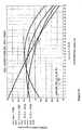
- Figure 13 illustrates a time-ordered, gradual increase/decrease of the azimuth value around the desired elevation angle only (resulting from motion of the airborne platform).
- the vertical and horizontal scales in Figure 13 represent nominal (true) azimuth and elevation angles to the emitter at the times that each of the measurements were taken.
- the legend on the vertical scale indicates the aircraft attitude (roll, pitch, and heading), the elevation angle to the emitter (e) which is unknown, and the measured AOA.
- the last four lines in the vertical legend indicate that the true azimuths at the four measurement times were 90°, 90.408°, 90.822° and 91.454° (the azimuth was changing due to the motion of the aircraft).
- the "e,e,e,e,16,16,16,16" legend on the horizontal scale indicates that the true elevation to the emitter was 16° at the four measurement times. In the exemplary embodiment shown in Figure 13 , it is shown that in the case of a moving aircraft, the unadjusted curves do not cross at single point that represents the true azimuth and elevation to the emitter.
- the azimuth changes from one measurement to the next, and the curves should not be expected to intercept around the operational elevation el - 16°. Indeed, because of the motion, the azimuth curves should show a very gradual change in value at the operational elevation angle (i.e., a change such as daz - ⁇ (daz/dt) ⁇ t, where ⁇ t is the interval between measurements).
- Figure 13 shows that a time-ordered, increase of azimuth values suggested by the flight path occurs only within a range of elevation values, roughly within, el ⁇ 13° to 20°.
- Figure 14 represents the same conditions as Figure 13 with one exception, that the measured AOA values shown in the vertical legend for the 2 nd , 3 rd and 4 th measurements include an additional term to account for the motion of the aircraft.
- the second line includes the term "-0.207x2".
- Figure 14 suggests an algorithmic procedure for the determination of the relative elevation angle between aircraft and emitter.
- a way to determine the relative elevation angle (el) is as follows.
- ⁇ ⁇ A ij el ⁇ A ( r i , p i , h i , el , ⁇ i ) - A ( r j , p j , h j , el , ⁇ j ) / t i - t j ⁇
- t i and t j are the times associated with the angle-of-arrival measurements ⁇ i and ⁇ j .
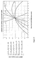
- Figure 15 shows that the azimuth-rate curves (6), all intercept at the correct elevation and approximate azimuth-rate value (e.g., average daz/dt ⁇ - 0.207 deg/sec.).
- the vertical axis on Figure 15 represents the azimuth rate of change between pairs of measurements, while the horizontal axis represents the elevation angle between the measurement aircraft and the emitter.
- the first expression (A(-10,15,30,e,-6.050)-A(0,0,ho,e,-23.969) represents the azimuth rate of change associated with measurements 1 and 2.
- This expression corresponds to the curve labeled "(1:2)".
- the second expression represents the azimuth rate of change between measurements 1 and 3, and this expression corresponds to the curve labeled "(1:3)”.
- the third expression represents the azimuth rate of change between measurements 1 and 4, and this expression corresponds to the curve labeled "(1:4)”.
- the fourth expression represents the azimuth rate of change between measurements 2 and 3, and this expression corresponds to the curve labeled "(2:3)”.
- the fifth expression represents the azimuth rate of change between measurements 2 and 4, and this expression corresponds to the curve labeled "(2:4)”.
- the sixth expression represents the azimuth rate of change between measurements 3 and 4, and this expression corresponds to the curve labeled "(3:4)".
- Figure 16 is a flow diagram illustrating a method of determining an azimuth and elevation of a radiation emission source using a single-axis direction finding system (e.g., an interferometer).
- a single-axis direction finding system e.g., an interferometer.
- a plurality of radiation signals are received at the single-axis direction finding system.
- the plurality of radiation signals are emitted from the radiation emission source.
- Each of the plurality of radiation signals is received at one of a plurality of attitudes of the single-axis direction finding system.
- an angle of arrival of each of the plurality of radiation signals is measured with respect to the single-axis direction finding system.
- an azimuth angle of each of the plurality of radiation signals is calculated with respect to the single-axis direction finding system using the respective measured angle of arrival.
- a respective vector corresponding to each of the azimuth angles is calculated at different elevation angles within a predetermined range.
- an elevation angle of the radiation emission source is determined by the point of convergence of the
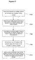
- Figure 17 is another flow diagram illustrating a method of determining an azimuth and elevation of a radiation emission source using a single-axis direction finding system.
- a plurality of radiation signals are received at the single - axis direction finding system.
- the plurality of radiation signals are emitted from the radiation emission source.
- Each of the plurality of radiation signals is received at one of a plurality of attitudes of the single-axis direction finding system.
- an angle of arrival of each of the plurality of radiation signals is measured with respect to the single-axis direction finding system.
- an azimuth angle of each of the plurality of radiation signals is calculated with respect to the single-axis direction finding system using the respective measured angle of arrival.
- a rate of change of the azimuth angle is calculated with respect to the plurality of radiation signals.
- an elevation angle of the radiation emission source with respect to the single-axis direction finding system is determined using the calculated rate of change of the azimuth angle.
- the present invention provides a method for airborne, passive determination of the earth-referenced azimuth and relative elevation angle to an emitter using a single-axis AOA measurement system, in conjunction with the platform's angular attitude-orientation reported by the GPS/INS.
- the method includes one or more of the following steps.
- the single-axis DF system receives radiation signals from the radiation emitter. These radiation signals are received at several different aircraft attitudes (heading, pitch, and roll), that is, at different angular attitudes of the interferometer attached to the aircraft.
- the set of measured angles-of-arrival ⁇ i ⁇ (r i , p i , h i , el, az i ), at the unknown elevation angle, el, is used by the established mathematical algorithm to calculate a group of azimuth angles.
- the algorithm suggests that the accuracy of the method is determined by the accuracy of the DF system used in the measurements, the angular separation of the aircraft attitudes used in the first step through the third step, the number of measurements, and to a lesser extent, by the accuracy associated with the GPS/INS system.
- the present concept considers a generic direction finding system (for example, a phase interferometer system) which is mounted on an aircraft (airborne platform).
- the measurements of the angle of arrival are performed not only at different aircraft headings, but may also be performed at generic angular attitudes (roll and pitch).
- the direction finding system can be mounted to any of a number of platforms, for example, stationary platforms on land, moving platforms on land, platforms on water, platforms in space, etc.
Landscapes
- Physics & Mathematics (AREA)
- Engineering & Computer Science (AREA)
- General Physics & Mathematics (AREA)
- Radar, Positioning & Navigation (AREA)
- Remote Sensing (AREA)
- Radar Systems Or Details Thereof (AREA)
- Navigation (AREA)
Claims (7)
- Verfahren zur Bestimmung von Azimuth und Elevation einer Strahlungsemissionsquelle (102) unter Verwendung eines einachsigen Ortungssystems aus einem Antennenpaar (230), welches Verfahren die Schritte enthält:Empfangen einer Vielzahl von Strahlungssignalen in dem einachsigen Ortungssystems sequenziell im Zeitverlauf (1602), welche Vielzahl von Strahlungssignalen von der Strahlungsemissionsquelle emittiert wird, wobei jedes der Vielzahl von Strahlungssignalen in einer einer Vielzahl von Lagen des einachsigen Ortungssystems empfangen wird; undMessen eines Einlaufwinkels jedes der Vielzahl von Strahlungssignalen in Bezug auf das einachsige Ortungssystem (1604) welches Verfahren gekennzeichnet ist durch:Berechnen eines Azimuthwinkels jedes der Vielzahl von Strahlungssignalen in Bezug auf das einachsige Ortungssystem (1606) unter Verwendung des jeweiligen gemessenen Einlaufwinkels;Berechnen eines jeweiligen Vektors entsprechend jedem der Azimuthwinkel bei unterschiedlichen Elevationswinkeln (1608) innerhalb eines vorbestimmten Bereichs von plausiblen Werten; undBestimmen eines Elevationswinkels der Strahlungsemissionsquelle in Bezug auf das einachsige Ortungssystem (1610) durch Bestimmen eines Konversionspunkts der Vektoren.
- Verfahren nach Anspruch 1, bei welchem der Schritt des Empfangens einer Vielzahl von Strahlungssignalen das Empfangen einer Vielzahl von Strahlungssignalen in dem einachsigen Ortungssystem enthält, wobei das einachsige Ortungssystem mit einer fliegenden Plattform (200) verbunden ist.
- Verfahren nach Anspruch 1 oder 2, zusätzlich enthaltend den Schritt:zumindest teilweises Korrigieren eines Präzessionsfehlers in dem berechneten Azimuthwinkel der Strahlungsemissionsquelle in Bezug auf das einachsige Ortungssystem unter Verwendung des bestimmten Elevationswinkels der Strahlungsemissionsquelle in Bezug auf das einachsige Ortungssystem.
- Verfahren nach einem der Ansprüche 1 bis 3, bei welchem der Schritt des Empfangens einer Vielzahl von Strahlungssignalen sequenziell im Zeitverlauf das Empfangen von mindestens drei Strahlungssignalen an mindestens drei unterschiedlichen Zeitpunkten in dem einachsigen Ortungssystem umfasst, wobei die drei Strahlungssignale von der Strahlungsquelle emittiert werden.
- Verfahren nach einem der Ansprüche 1 bis 4, bei welchem der Schritt des Empfangens einer Vielzahl von Strahlungssignalen das Empfangen jedes der Vielzahl von Strahlungssignalen in mindestens einer der Fluglagen Kurs, Rollen und Nicken des einachsigen Ortungssystems umfasst.
- Verfahren nach einem der Ansprüche 1 bis 5, bei welchem das Berechnen eines Azimuthwinkels das Berechnen eines Azimuthwinkels jedes der Vielzahl von Strahlungssignalen in Bezug auf das einachsige Ortungssystem unter Verwendung des jeweiligen gemessenen Einlaufwinkels, einer jeweiligen Fluglage des einachsigen Ortungssystems und des bestimmten Elevationswinkel der Strahlungsemissionsquelle in Bezug auf das einachsige Ortungssystem umfasst.
- Verfahren nach Anspruch 2, bei welchem die Vektoren der Azimuth-Veränderungsgeschwindigkeit für Korrekturen der Bewegung der fliegenden Plattform berechnet werden unter Verwendung der Beziehung:

worin el einen Elevationswinkelbereich darstellt, θi und θj zwei der Einlaufwinkelmessungen sind,
ti und tj die den Einlaufwinkelmessungen zugeordneten Zeitpunkte sind, ri und rj Roll-Fluglagenwerte des Luftfahrzeugs sind, pi und pj Nick-Fluglagenwerte des Luftfahrzeugs sind und hi und hj Kurs-Fluglagenwerte des Luftfahrzeugs sind.
Applications Claiming Priority (3)
| Application Number | Priority Date | Filing Date | Title |
|---|---|---|---|
| US10/328,543 US6784840B2 (en) | 2002-12-23 | 2002-12-23 | Method for determining azimuth and elevation angles using a single axis direction finding system |
| US328543 | 2002-12-23 | ||
| PCT/US2003/040339 WO2005059584A1 (en) | 2002-12-23 | 2003-12-19 | Method of determining azimuth and elevation angles using a single axis direction finding system |
Publications (2)
| Publication Number | Publication Date |
|---|---|
| EP1579235A1 EP1579235A1 (de) | 2005-09-28 |
| EP1579235B1 true EP1579235B1 (de) | 2008-02-27 |
Family
ID=32594509
Family Applications (1)
| Application Number | Title | Priority Date | Filing Date |
|---|---|---|---|
| EP03819050A Expired - Lifetime EP1579235B1 (de) | 2002-12-23 | 2003-12-19 | Verfahren zur bestimmung von azimut- undhöhenwinkeln durch verwendung eines einachsen-richtungfindungssystems |
Country Status (6)
| Country | Link |
|---|---|
| US (1) | US6784840B2 (de) |
| EP (1) | EP1579235B1 (de) |
| AU (1) | AU2003304615A1 (de) |
| DE (1) | DE60319426T2 (de) |
| IL (1) | IL169042A (de) |
| WO (1) | WO2005059584A1 (de) |
Families Citing this family (39)
| Publication number | Priority date | Publication date | Assignee | Title |
|---|---|---|---|---|
| TWI250302B (en) * | 2004-09-20 | 2006-03-01 | Wintecronics Co Ltd | Mutual angle correction method for navigation device, and the device thereof |
| US7499803B2 (en) * | 2006-02-10 | 2009-03-03 | Honeywell International Inc. | System and method for calibrating on-board aviation equipment |
| RU2325666C2 (ru) * | 2006-06-23 | 2008-05-27 | Военно-космическая академия имени А.Ф. Можайского | Разностно-дальномерный способ пеленгования источника радиоизлучения |
| US7637192B2 (en) * | 2006-10-26 | 2009-12-29 | Blount, Inc. | Saw chain drive link with tail |
| RU2382378C1 (ru) * | 2008-06-05 | 2010-02-20 | Государственное образовательное учреждение высшего профессионального образования "Военно-космическая академия имени А.Ф. Можайского" | Разнесенный разностно-дальномерный пеленгатор |
| FR2940686B1 (fr) * | 2008-12-30 | 2011-03-18 | Thales Sa | Procede et systeme de localisation d'une cible dans un systeme interrogation reponse (iff). |
| US8217836B1 (en) * | 2010-02-26 | 2012-07-10 | Rockwell Collins, Inc. | Tactical relative navigation using orientation transfer and ranging |
| US8779971B2 (en) | 2010-05-24 | 2014-07-15 | Robert J. Wellington | Determining spatial orientation information of a body from multiple electromagnetic signals |
| RU2470315C1 (ru) * | 2011-04-28 | 2012-12-20 | Федеральное государственное унитарное предприятие "Центральный научно-исследовательский радиотехнический институт имени академика А.И. Берга" | Способ компьютерно-интерферометрического обнаружения-пеленгования радиосигналов с расширенным спектром |
| US8830122B2 (en) | 2011-06-10 | 2014-09-09 | Exelis, Inc. | Phase rate of change techniques for passive geo-location of radio frequency emitters |
| CN102419430B (zh) * | 2011-08-17 | 2013-04-17 | 电子科技大学 | 一种基于平行基线的圆阵相位干涉仪二维测向方法 |
| US9052203B2 (en) * | 2012-03-17 | 2015-06-09 | Mcube, Inc. | Methods and apparatus for low-cost inertial dead-reckoning using context detection |
| CN102735207B (zh) * | 2012-06-18 | 2014-11-19 | 西安空间无线电技术研究所 | 一种基于距离和载波相差的二维角度解算方法 |
| CN102736057B (zh) * | 2012-06-18 | 2014-05-28 | 西安空间无线电技术研究所 | 一种基于距离和跟踪再生载波相位的二维角度解算方法 |
| US20140004877A1 (en) * | 2012-06-29 | 2014-01-02 | Broadcom Corporation | Position Determination Using Round-Trip Delay and Angle-of-Arrival |
| ES2771524T3 (es) | 2012-07-03 | 2020-07-06 | Saab Ab | Procedimiento de determinación de una dirección a un objeto emisor de señal |
| RU2518015C1 (ru) * | 2012-10-02 | 2014-06-10 | Федеральное государственное бюджетное образовательное учреждение высшего профессионального образования Томский государственный университет систем управления и радиоэлектроники | Способ повышения точности оценки разности моментов приема радиосигналов за счет использования особенностей канала распространения радиоволн |
| RU2539968C1 (ru) * | 2013-12-27 | 2015-01-27 | Константин Леонидович Овчаренко | Разностно-дальномерный способ определения координат источника радиоизлучения |
| US10320073B2 (en) * | 2014-01-14 | 2019-06-11 | Viasat, Inc. | Mobile terminal antenna alignment using arbitrary orientation attitude |
| US9739878B2 (en) | 2014-03-25 | 2017-08-22 | Raytheon Company | Methods and apparatus for determining angle of arrival (AOA) in a radar warning receiver |
| RU2562828C1 (ru) * | 2014-05-08 | 2015-09-10 | Федеральное государственное унитарное предприятие "Всероссийский научно-исследовательский институт автоматики им. Н.Л. Духова" (ФГУП "ВНИИА") | Устройство для определения направления и дальности до источника сигнала |
| RU2568897C1 (ru) * | 2014-10-06 | 2015-11-20 | Андрей Борисович Махетов | Способ измерения взаимной задержки сигналов |
| CN104807464B (zh) * | 2015-04-22 | 2017-12-01 | 深圳市视晶无线技术有限公司 | 飞行器近场引导方法 |
| FR3041766B1 (fr) * | 2015-09-25 | 2019-03-29 | Thales | Procede de localisation passive d'emetteurs electromagnetiques au sol, utilisation, et dispositif associe |
| CN106643807A (zh) * | 2017-01-16 | 2017-05-10 | 中国人民解放军军械工程学院 | 管状体方位角定向装置精度检测方法 |
| US10211508B2 (en) | 2017-07-06 | 2019-02-19 | Viasat, Inc. | Dynamic antenna platform offset calibration |
| CN107796836B (zh) * | 2017-09-19 | 2021-05-18 | 中铝材料应用研究院有限公司 | 一种修正板材织构欧拉角的方法 |
| CN108872933B (zh) * | 2018-07-16 | 2022-02-08 | 电子科技大学 | 一种单站盲干涉仪定位方法 |
| CN110823212B (zh) * | 2018-08-14 | 2023-04-07 | 北京自动化控制设备研究所 | 一种基于粒子滤波的sins/dr组合导航系统位置跟踪确定方法 |
| US11513196B2 (en) * | 2018-09-28 | 2022-11-29 | Waymo Llc | Terrain adaptive pulse power in a scanning LIDAR |
| CN111722177B (zh) * | 2019-03-22 | 2023-06-16 | 成都信息工程大学 | 确定辐射源定向误差的方法 |
| CN112400118B (zh) * | 2019-06-13 | 2024-04-09 | 深圳市速腾聚创科技有限公司 | 坐标校正方法、装置、计算设备及计算机存储介质 |
| CN110208741B (zh) * | 2019-06-28 | 2022-12-02 | 电子科技大学 | 一种基于多圆阵测相的超视距单目标直接定位方法 |
| CN111487581B (zh) * | 2020-04-20 | 2022-02-11 | 中国人民解放军军事科学院国防科技创新研究院 | 基于舵矢量模式匹配的宽带闪电vhf辐射源测向方法 |
| US11550021B2 (en) * | 2020-11-25 | 2023-01-10 | Rohde & Schwarz Gmbh & Co. Kg | Method and direction finding system for localizing a near vertical incidence skywave emitter |
| CN112697129B (zh) * | 2020-12-15 | 2023-05-05 | 电子科技大学 | 一种利用一维测角确定天线线阵二维姿态的快速方法 |
| CN114184151B (zh) * | 2021-12-15 | 2024-01-02 | 上海无线电设备研究所 | 一种单轴坐标外推方法 |
| CN114363805B (zh) * | 2021-12-29 | 2024-04-30 | 北京红山信息科技研究院有限公司 | 一种纠正背向点的三角定位改进方法 |
| US20250267501A1 (en) * | 2024-02-20 | 2025-08-21 | Qualcomm Incorporated | Field of view determination based on an elevation angle between devices |
Family Cites Families (7)
| Publication number | Priority date | Publication date | Assignee | Title |
|---|---|---|---|---|
| US5198822A (en) * | 1992-02-24 | 1993-03-30 | Westinghouse Electric Corp. | Method and apparatus for determining the angle of arrival of a radar signal at a spinning interferometer |
| US5526001A (en) * | 1992-12-11 | 1996-06-11 | Litton Systems Inc. | Precise bearings only geolocation in systems with large measurements bias errors |
| US5343212A (en) * | 1992-12-11 | 1994-08-30 | Litton Industries, Inc. | (AOA/LBI) emitter ranging method and apparatus |
| US5457466A (en) * | 1993-09-07 | 1995-10-10 | Litton Systems Inc. | Emitter azimuth and elevation direction finding using only linear interferometer arrays |
| US5905463A (en) * | 1997-04-21 | 1999-05-18 | Marconi Aerospace Systems Inc. Advanced Systems Division | Linear array aircraft antenna with coning correction |
| US6225949B1 (en) * | 1998-12-22 | 2001-05-01 | Lockheed Martin Corporation | Method and apparatus for a ring interferometer |
| US6061022A (en) * | 1999-06-04 | 2000-05-09 | Itt Manufacturing Enterprises, Inc. | Azimuth and elevation direction finding system based on hybrid amplitude/phase comparison |
-
2002
- 2002-12-23 US US10/328,543 patent/US6784840B2/en not_active Expired - Fee Related
-
2003
- 2003-12-19 WO PCT/US2003/040339 patent/WO2005059584A1/en not_active Ceased
- 2003-12-19 EP EP03819050A patent/EP1579235B1/de not_active Expired - Lifetime
- 2003-12-19 DE DE60319426T patent/DE60319426T2/de not_active Expired - Lifetime
- 2003-12-19 AU AU2003304615A patent/AU2003304615A1/en not_active Abandoned
-
2005
- 2005-06-07 IL IL169042A patent/IL169042A/en not_active IP Right Cessation
Also Published As
| Publication number | Publication date |
|---|---|
| DE60319426T2 (de) | 2009-03-19 |
| EP1579235A1 (de) | 2005-09-28 |
| US6784840B2 (en) | 2004-08-31 |
| AU2003304615A1 (en) | 2005-07-05 |
| WO2005059584A1 (en) | 2005-06-30 |
| US20040119640A1 (en) | 2004-06-24 |
| IL169042A (en) | 2010-11-30 |
| DE60319426D1 (de) | 2008-04-10 |
Similar Documents
| Publication | Publication Date | Title |
|---|---|---|
| EP1579235B1 (de) | Verfahren zur bestimmung von azimut- undhöhenwinkeln durch verwendung eines einachsen-richtungfindungssystems | |
| US4405986A (en) | GSP/Doppler sensor velocity derived attitude reference system | |
| US9304198B1 (en) | Navigator alignment using radar scan | |
| US5457466A (en) | Emitter azimuth and elevation direction finding using only linear interferometer arrays | |
| US8791859B2 (en) | High precision radio frequency direction finding system | |
| CN105242285B (zh) | 一种基于卫星通信的无人机导航数据被欺骗识别方法 | |
| CN105068065B (zh) | 星载激光测高仪在轨检校方法及系统 | |
| US10670689B2 (en) | System and method for determining geo location of a target using a cone coordinate system | |
| US12510657B2 (en) | Method for locating an aircraft in flight | |
| CN117970382B (zh) | 一种gnss仿真测试方法及系统 | |
| US6594582B1 (en) | GPS compound eye attitude and navigation sensor and method | |
| CN114838731A (zh) | 飞机在进近阶段基于航向信标和测距仪的定位方法和系统 | |
| US9383429B2 (en) | System and method for determining geo location of a target using locus of emitter positions (LEP) | |
| US4179697A (en) | Passive ranging method | |
| CN109471102B (zh) | 一种惯组误差修正方法 | |
| CN119902231A (zh) | 一种基于浮动平台的测风激光雷达风场反演优化方法、系统、设备和介质 | |
| CN111337055B (zh) | 一种卫星移动通信天线惯导的标校方法 | |
| CN116465402A (zh) | 用于民用飞机的irs/dme/loc组合导航方法及组合导航终端 | |
| CN108872933B (zh) | 一种单站盲干涉仪定位方法 | |
| US8436762B2 (en) | Determining at least one coordinate of an object using intersecting surfaces | |
| RU2857241C1 (ru) | Способ определения местоположения и угловой ориентации объекта навигации | |
| O'Day | Final report | |
| Shank | A coordinate conversion algorithm for multisensor data processing | |
| CN115438296B (zh) | 基于方程的动目标空间方位角精确求解方法 | |
| CN119414381B (zh) | 一种飞行器导航定位方法及系统 |
Legal Events
| Date | Code | Title | Description |
|---|---|---|---|
| PUAI | Public reference made under article 153(3) epc to a published international application that has entered the european phase |
Free format text: ORIGINAL CODE: 0009012 |
|
| AK | Designated contracting states |
Kind code of ref document: A1 Designated state(s): AT BE BG CH CY CZ DE DK EE ES FI FR GB GR HU IE IT LI LU MC NL PT RO SE SI SK TR |
|
| AX | Request for extension of the european patent |
Extension state: AL LT LV MK |
|
| 17P | Request for examination filed |
Effective date: 20051230 |
|
| RBV | Designated contracting states (corrected) |
Designated state(s): DE FR GB IT |
|
| DAX | Request for extension of the european patent (deleted) | ||
| RBV | Designated contracting states (corrected) |
Designated state(s): DE FR GB IT |
|
| GRAP | Despatch of communication of intention to grant a patent |
Free format text: ORIGINAL CODE: EPIDOSNIGR1 |
|
| GRAS | Grant fee paid |
Free format text: ORIGINAL CODE: EPIDOSNIGR3 |
|
| GRAA | (expected) grant |
Free format text: ORIGINAL CODE: 0009210 |
|
| AK | Designated contracting states |
Kind code of ref document: B1 Designated state(s): DE FR GB IT |
|
| REG | Reference to a national code |
Ref country code: GB Ref legal event code: FG4D |
|
| REF | Corresponds to: |
Ref document number: 60319426 Country of ref document: DE Date of ref document: 20080410 Kind code of ref document: P |
|
| ET | Fr: translation filed | ||
| PLBE | No opposition filed within time limit |
Free format text: ORIGINAL CODE: 0009261 |
|
| STAA | Information on the status of an ep patent application or granted ep patent |
Free format text: STATUS: NO OPPOSITION FILED WITHIN TIME LIMIT |
|
| 26N | No opposition filed |
Effective date: 20081128 |
|
| REG | Reference to a national code |
Ref country code: GB Ref legal event code: 732E Free format text: REGISTERED BETWEEN 20120906 AND 20120912 |
|
| REG | Reference to a national code |
Ref country code: FR Ref legal event code: CD Owner name: EXELIS INC., US Effective date: 20120912 Ref country code: FR Ref legal event code: TP Owner name: EXELIS INC., US Effective date: 20120912 |
|
| REG | Reference to a national code |
Ref country code: FR Ref legal event code: PLFP Year of fee payment: 13 |
|
| PGFP | Annual fee paid to national office [announced via postgrant information from national office to epo] |
Ref country code: GB Payment date: 20151229 Year of fee payment: 13 |
|
| PGFP | Annual fee paid to national office [announced via postgrant information from national office to epo] |
Ref country code: FR Payment date: 20151217 Year of fee payment: 13 |
|
| PGFP | Annual fee paid to national office [announced via postgrant information from national office to epo] |
Ref country code: DE Payment date: 20151229 Year of fee payment: 13 |
|
| PG25 | Lapsed in a contracting state [announced via postgrant information from national office to epo] |
Ref country code: IT Free format text: LAPSE BECAUSE OF NON-PAYMENT OF DUE FEES Effective date: 20151219 |
|
| REG | Reference to a national code |
Ref country code: DE Ref legal event code: R119 Ref document number: 60319426 Country of ref document: DE |
|
| GBPC | Gb: european patent ceased through non-payment of renewal fee |
Effective date: 20161219 |
|
| PG25 | Lapsed in a contracting state [announced via postgrant information from national office to epo] |
Ref country code: IT Free format text: LAPSE BECAUSE OF NON-PAYMENT OF DUE FEES Effective date: 20151219 |
|
| PGFP | Annual fee paid to national office [announced via postgrant information from national office to epo] |
Ref country code: IT Payment date: 20151222 Year of fee payment: 13 |
|
| PGRI | Patent reinstated in contracting state [announced from national office to epo] |
Ref country code: IT Effective date: 20170710 |
|
| REG | Reference to a national code |
Ref country code: FR Ref legal event code: ST Effective date: 20170831 |
|
| PG25 | Lapsed in a contracting state [announced via postgrant information from national office to epo] |
Ref country code: IT Free format text: LAPSE BECAUSE OF NON-PAYMENT OF DUE FEES Effective date: 20161219 Ref country code: FR Free format text: LAPSE BECAUSE OF NON-PAYMENT OF DUE FEES Effective date: 20170102 |
|
| PGRI | Patent reinstated in contracting state [announced from national office to epo] |
Ref country code: IT Effective date: 20170710 |
|
| PG25 | Lapsed in a contracting state [announced via postgrant information from national office to epo] |
Ref country code: DE Free format text: LAPSE BECAUSE OF NON-PAYMENT OF DUE FEES Effective date: 20170701 Ref country code: GB Free format text: LAPSE BECAUSE OF NON-PAYMENT OF DUE FEES Effective date: 20161219 |