EP1579152B1 - Mikrowellenofen - Google Patents
Mikrowellenofen Download PDFInfo
- Publication number
- EP1579152B1 EP1579152B1 EP03813987A EP03813987A EP1579152B1 EP 1579152 B1 EP1579152 B1 EP 1579152B1 EP 03813987 A EP03813987 A EP 03813987A EP 03813987 A EP03813987 A EP 03813987A EP 1579152 B1 EP1579152 B1 EP 1579152B1
- Authority
- EP
- European Patent Office
- Prior art keywords
- microwave oven
- door
- outer casing
- convexo
- concave
- Prior art date
- Legal status (The legal status is an assumption and is not a legal conclusion. Google has not performed a legal analysis and makes no representation as to the accuracy of the status listed.)
- Expired - Lifetime
Links
- 230000002787 reinforcement Effects 0.000 claims abstract description 69
- 238000010411 cooking Methods 0.000 claims abstract description 34
- 230000003014 reinforcing effect Effects 0.000 claims description 50
- 230000000994 depressogenic effect Effects 0.000 claims description 7
- 238000009434 installation Methods 0.000 description 9
- 239000011359 shock absorbing material Substances 0.000 description 7
- 239000002184 metal Substances 0.000 description 4
- 229910000831 Steel Inorganic materials 0.000 description 3
- 238000005452 bending Methods 0.000 description 3
- 238000004806 packaging method and process Methods 0.000 description 3
- 230000035939 shock Effects 0.000 description 3
- 239000010959 steel Substances 0.000 description 3
- 239000003990 capacitor Substances 0.000 description 2
- 238000001816 cooling Methods 0.000 description 2
- 238000010438 heat treatment Methods 0.000 description 2
- 238000000034 method Methods 0.000 description 2
- 230000002093 peripheral effect Effects 0.000 description 2
- 238000011084 recovery Methods 0.000 description 2
- 238000003466 welding Methods 0.000 description 2
- 230000003796 beauty Effects 0.000 description 1
- 238000006243 chemical reaction Methods 0.000 description 1
- 230000008878 coupling Effects 0.000 description 1
- 238000010168 coupling process Methods 0.000 description 1
- 238000005859 coupling reaction Methods 0.000 description 1
- 239000011521 glass Substances 0.000 description 1
- 230000001678 irradiating effect Effects 0.000 description 1
- 230000007774 longterm Effects 0.000 description 1
- 239000000463 material Substances 0.000 description 1
- 239000012779 reinforcing material Substances 0.000 description 1
Images


Classifications
-
- H—ELECTRICITY
- H05—ELECTRIC TECHNIQUES NOT OTHERWISE PROVIDED FOR
- H05B—ELECTRIC HEATING; ELECTRIC LIGHT SOURCES NOT OTHERWISE PROVIDED FOR; CIRCUIT ARRANGEMENTS FOR ELECTRIC LIGHT SOURCES, IN GENERAL
- H05B6/00—Heating by electric, magnetic or electromagnetic fields
- H05B6/64—Heating using microwaves
- H05B6/6426—Aspects relating to the exterior of the microwave heating apparatus, e.g. metal casing, power cord
-
- F—MECHANICAL ENGINEERING; LIGHTING; HEATING; WEAPONS; BLASTING
- F24—HEATING; RANGES; VENTILATING
- F24C—DOMESTIC STOVES OR RANGES ; DETAILS OF DOMESTIC STOVES OR RANGES, OF GENERAL APPLICATION
- F24C15/00—Details
- F24C15/08—Foundations or supports plates; Legs or pillars; Casings; Wheels
-
- H—ELECTRICITY
- H05—ELECTRIC TECHNIQUES NOT OTHERWISE PROVIDED FOR
- H05B—ELECTRIC HEATING; ELECTRIC LIGHT SOURCES NOT OTHERWISE PROVIDED FOR; CIRCUIT ARRANGEMENTS FOR ELECTRIC LIGHT SOURCES, IN GENERAL
- H05B6/00—Heating by electric, magnetic or electromagnetic fields
- H05B6/64—Heating using microwaves
- H05B6/6414—Aspects relating to the door of the microwave heating apparatus
Definitions
- the present invention relates to a microwave oven, and more particularly, to a microwave oven wherein rigidity of parts for defining an exterior appearance of the microwave oven is improved.
- a microwave oven is one of electronic home appliances for kitchen for cooking food using frictional heat between molecules generated while disturbing molecular structures of the food by irradiating microwaves, which serves as a heating source, onto the food.
- the microwave oven is widely used not only in home but also in restaurants, feeding facilities or the like where a large quantity of food is simultaneously cooked, because of convenience of use for easy heating and cooking of food.
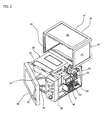
- FIG. 1 A typical example of such a microwave oven is shown in FIG. 1 .
- a cavity assembly 1 functions as a framework of a microwave oven.
- a cooking chamber 3 in which food is cooked is defined in the cavity assembly 1, and an electronic equipment installation chamber 5 is formed at one side of the cavity assembly 1 in a state where it is partitioned from the cooking chamber 3.
- a turntable 7 for turning the food thereon is installed in the cooking chamber 3.
- Parts for generating microwaves, such as a magnetron 9, a high voltage transformer 10 and a capacitor 11, are also installed in the electronic equipment installation chamber 5.
- a blower fan 12 for cooling the aforementioned parts and generating airflow into/from the cooking chamber 3 is also provided in the electronic equipment installation chamber 5.
- a door 13 for causing the cooking chamber 3 to be open and close is fixed and installed to one side of a front face of the cavity assembly 1.
- the door 13 is hingedly connected to the cavity assembly 1 and provided with a handle 15 at a side of a front surface of the door opposite to the side to which the door is hingedly connected.
- a control unit 17 for controlling the microwave oven is provided at the other side of the cavity assembly 1.
- an outer casing 19 which is made of a metal plate, defines an external appearance of the microwave oven at top and side surfaces thereof.
- the outer casing 19 is mounted to the cavity assembly 1 so as to enclose the cavity assembly 1 and to shield the electronic equipment installation chamber 5 from the outside.
- a back plate 1' defines a rear face of the cavity assembly 1, more generally, a whole rear surface of the microwave oven.
- the microwave oven constructed as such is operated in the following manner. That is, after the door 13 is opened, food to be cooked is put onto the turntable 7 in the cooking chamber 3, and the door 13 is then closed. Thereafter, the control unit 17 is operated to select and begin a desired cooking mode.
- the external appearance of the microwave oven is generally defined by the parts such as the back plate 1', the door 13 and the outer casing 19. In such a case, the external parts may be damaged by a variety of external forces.
- the outer casing 19 is generally formed of a metal plate and defines the top surface and two opposite side surfaces of the microwave oven. Since the surfaces of the microwave oven are planar as a whole, they have weak resistance to the external forces. In particular, in a case where a surface area of the outer casing 19 becomes large as the size of the microwave oven is increased, rigidity of the outer casing 19 is relatively reduced and thus the deformation thereof are frequently produced.
- a clamping means is frequently used to carry the microwave oven.
- a clamping force produced when carrying the microwave oven is transmitted to a packaging box of the microwave oven, and thus, any deformation may be produced at the outer casing 19 or corners of the microwave oven.
- a disposable reinforcing material may be used, which results in an increase of costs and inconvenience in handling of the microwave oven.
- the microwave oven may inadvertently drop when carrying the microwave oven. At this time, if the microwave oven drops and one of the corners thereof comes into contact with the ground, impact load applied to the microwave oven is concentrated on the corner which in turn may be greatly deformed.
- the back plate 1' defines the external appearance of the microwave oven as well as a rear face of the cavity assembly 1.
- the back plate 1' has a problem in that either border regions excluding portions to be welded for constituting the cavity assembly 1 or regions adjacent to a hole through which a power cable is drawn to the outside are relatively weak in view of their rigidity.
- the door 13 also defines the external appearance of the microwave oven, and a force for opening the door 13 may cause the microwave oven to be deformed. That is, the handle 15 should be pulled outwards so as to open the door 13. However, since the door 13 is in a state where it is locked or fastened to the cavity assembly 1 with a latch (not shown), the door 13 cannot be opened until a force enough to overcome the locking force of the latch is applied thereto.
- the force exerted on the handle for opening the door 13 causes the door to be deformed or twisted, and consequently, a gap may be generated between a rear surface of the door 13 and the front face of the cavity assembly 1 due to repeated use of the door. Electromagnetic waves leak from the interior of the cooking chamber 3 through the gap, thereby exerting a bad influence on a user and causing cooking time to be lengthened.
- KR 960003106 y teaches a microwave oven corresponding the preamble of claim 1.
- an object of the present invention is to increase rigidity of parts for defining an external appearance of a microwave oven.
- Another object of the present invention is to increase rigidity of an outer casing of the microwave oven.
- a further object of the present invention is to increase rigidity of edge portions of the microwave oven.
- a still further object of the present invention is to increase rigidity of a back plate of the microwave oven.
- a still further object of the present invention is to increase rigidity of a door of the microwave oven.
- the convexo-concave reinforcement is formed horizontally at an upper end of the back plate that adjoins a top surface of the outer casing, and the depth of the convexo-concave reinforcement is within a range of 1 to 8 mm. More preferably, the convexo-concave reinforcement is protruded or depressed uniformly as a whole.
- an additional convexo-concave reinforcement is formed in the back plate at a position adjacent to a perforated cord hole, and the additional convexo-concave reinforcement is rectangular.
- the convexo-concave reinforcements are formed on all of the top and side portions, and a depth of each of the convexo-concave reinforcements is within a range of 0.5 to 5.0 mm. Further, each of the convexo-concave reinforcements may be formed to have the same depth throughout the reinforcement.
- a depth of the convexo-concave reinforcement formed at the side portion of the outer casing becomes smaller in a downward direction of the side portion.
- an angle between a line L extending along an external edge of the outer casing and a border line of the chamfer is within a range of 30 to 60 degrees, and the chamfers are formed at least at rear corners of the outer casing.
- a protruding portion and a recessed portion are formed in parallel along edges of the door frame, and a choke structure for preventing microwaves from leaking out is provided along edges of a rear surface of the door frame.
- the reinforcing member is preferably bent several times perpendicularly to a longitudinal direction thereof so that it can be simultaneously mounted on the protruding and recessed portions.
- the reinforcing member is bent once perpendicularly to a longitudinal direction thereof so that it can be mounted on a surface of the protruding portion and a connecting surface between the protruding and recessed portions.
- the reinforcing member may be formed of an elongated plate with a predetermined width corresponding to that of the protruding portion so that it can be mounted on the protruding portion.
- the reinforcing member may be mounted on a rear surface of the door panel for connection with the handle and includes mounting portions fastened to the handle at both ends thereof and a linking portion with a predetermined length for linking the mounting portions.
- a cross-sectional length of the linking portion of the reinforcing member is preferably formed to be smaller than those of the mounting portions.
- microwave oven of the present invention constructed as such, there is an advantage in that rigidity of external parts of the microwave oven can be relatively enhanced.
- air inlet holes 33a are formed in the back plate 33 at a position corresponding to the electronic equipment installation chamber 32.
- a cord hole 33h is formed on an upper portion of the back plate 33 corresponding to the electronic equipment installation chamber 32.
- a power cord for supplying the microwave oven with electric power passes through the cord hole 33h.
- An elongated convexo-concave reinforcement 33' is formed at an upper end of the back plate 33, i.e. along a portion that is screwed and connected to a top portion 41 of an outer casing 40 to be described later. If the upper end of the back plate 33 is merely connected to the outer casing 40 without any support of an additional structure, it may be easily deformed. Thus, the convexo-concave reinforcement 33' can prevent this possible deformation of the upper center portion of the back plate 33.
- the convexo-concave reinforcement 33' is preferably depressed as viewed from the outside of the back plate 33. Such a convexo-concave reinforcement 33' functions to reinforce the rigidity of the back plate 33 and may be manufactured through press working.
- the back plate 33 since the back plate 33 is used to define the rear surface of the microwave oven, it is not easily exposed to a user when it is actually in use. Therefore, since external beauty of the back plate is of little importance, the back plate 33 can be sufficiently reinforced without any limitation on depths or heights of the convexo-concave reinforcements 33' and 33".
- the convexo-concave reinforcements 33' and 33" are formed to have relatively large depths or heights, there is a problem in that press workability therefor is reduced.
- the convexo-concave reinforcements 33' and 33" are excessively depressed or protruded, they may interfere with peripheral other parts or structures of the microwave oven.
- the inventors of the present invention conducted tests for the depths of the convexo-concave reinforcements 33' and 33". As a result, it is most preferred that the depths of the reinforcements be within a range of 1 to 8 mm.
- the test results were obtained based on the back plate 33 made of a steel plate generally having a thickness of 0.5 to 0.7 mm.
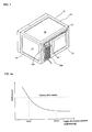
- FIG. 4a shows the relationship between the depth of convexo-concave reinforcement 33' or 33" and the deformation thereof due to an external force.
- the convexo-concave reinforcements 33' and 33" are formed on the back plate 33, bending moment of inertia of the back plate is increased. Therefore, the deformation due to the external force is remarkably reduced. If the deformation is below a critical deformation, an original shape of the back plate can be sufficiently maintained due to an elastic recovery characteristic. Consequently, the rigidity of the back plate against the external force can be remarkably increased as compared with that of the conventional plate.
- a turntable 35 is installed within the cooking chamber 31.
- the turntable 35 allows the food thereon to be turned and thus microwaves to be uniformly transmitted to the food.
- a magnetron 36, a high-voltage transformer 37, and a high-voltage capacitor 38 are installed in the chamber 32. Further, a blower fan 39 for cooling the above parts is also provided.
- Each of the top portion 41 and side portions 43 of the outer casing 40 is provided with a convexo-concave reinforcement 45.
- the convexo-concave reinforcement 45 is formed to be depressed in a direction by performing press working for regions adjacent to borders of the top portions 41 and the side portions 43.
- all the reinforcements 45 of the top portion 41 and the side portions 43 of the outer casing 40 have rectangular shapes and are formed to be concave as viewed from the outside.
- a predetermined space is provided between the borders of the convexo-concave reinforcements 45 and the borders of the top portion 41 and the side portions 43.
- the rigidity of the outer casing 40 can be remarkably improved by further forming the convexo-concave reinforcements 45 on the top portion 41 and the side portions 43 of the outer casing 40.
- the rigidity of the border portions where the top portion 41 and the side portions 43 intersect with each other are further remarkably enhanced.
- the convexo-concave reinforcements 45 are formed to be depressed inwardly from the external surface of the outer casing 40.
- the present invention is not limited thereto.
- the reinforcements may be formed to protrude outwardly from the external surface of the top portion 41 and the side portions 43 of the outer casing 40.
- each of the convexo-concave reinforcements 45 should be formed to have an appropriate depth or height.
- the depth or height of the reinforcement 45 is excessively large, the workability for the reinforcement is deteriorated and the reinforcement may interfere with the peripheral structures.
- FIG. 4b shows the relationship between the depth of the convexo-concave reinforcement 45 and the deformation thereof due to an external force. That is, if the convexo-concave reinforcements 45 are formed on the outer casing 40 as in the example disclosing certain features of the present invention, bending moment of inertia of the outer casing is increased. Therefore, the deformation due to the external force is remarkably reduced. If the deformation is below a critical deformation, an original shape of the outer casing can be sufficiently maintained due to an elastic recovery characteristic. Consequently, the rigidity of the outer casing against the external force can be remarkably increased as compared with that of the conventional casing.
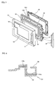
- a door 50 is used to cause the cooking chamber 31 of the cavity assembly 30 to be open and close.
- the door 50 is hingedly connected to one side of the front plate 34 of the cavity assembly 30, and provided with a handle 51 at a side of a front surface thereof opposite to the side to which the door is hingedly connected.
- a door panel 52 defines an external appearance of the door 50.
- the handle 51 is provided on the one side of the front surface of the door panel 52.
- a glass plate 53 through which the interior of the cooking chamber 31 can be viewed is fixed to the center of the front surface of the door panel 52 by a decorative plate 53'.
- a door frame 54 is provided at a rear surface of the door panel 52.
- the door frame 54 functions as a framework of the door 50 and is provided at the center thereof with a porous zinc-plated steel plate 55 for allowing the electromagnetic waves to be shielded and also the interior of the cooking chamber 31 to be viewed.
- a protruding portion 54a is formed along a front edge portion of the door frame 54, and a recessed portion 54b is also formed inside of the protruding portion 54. The recessed portion 54b is depressed inwardly from a front surface of the door frame 54 as compared with the protruding portion 54a.
- a choke structure 56 is formed along a rear edge portion of the door frame 54, and functions to prevent the electromagnetic waves in the cooking chamber 31 from leaking to the outside through the door 50.
- Reference numeral 57 denotes a latch for keeping the door 50 closed.
- a choke cover 58 is also mounted to a rear surface of the door frame 54.
- the choke cover 58 defines a rear border of the door 50 and functions to shield the choke structure 56.
- a reinforcing plate 59 is provided at one side of the door frame 54.
- the reinforcing plate 59 is installed at the same side of the door frame 54 where the handle 51 is provided on the door panel 52.
- the reinforcing plate 59 is mounted to the door frame 54 by means of a predetermined process such as a welding process.
- the reinforcing plate 59 is formed to come into close contact with a front surface of the protruding portion 54a, a floor surface of the recessed portion 54b and a connecting surface between the protruding and recessed portions 54a and 54b. That is, the reinforcing plate 59 is bent twice in a direction perpendicular to a longitudinal direction thereof.
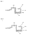
- FIG. 7 shows a modified example of a reinforcing plate 59' of the door frame 54.
- the reinforcing plate 59' is formed to come into close contact with the front surface of the protruding portion 54a and the connecting surface between the protruding and recessed portions 54a and 54b. That is, the reinforcing plate 59' is bent only once in a direction perpendicular to a longitudinal direction thereof.
- FIG. 8 shows another modified example of a reinforcing plate 59" of the door frame 54.
- the reinforcing plate 59" is attached to the front surface of the protruding portion 54a.
- the reinforcing plate 59" is manufactured in the form of an elongated band.
- the reinforcing plate 59 of FIG. 6 can relatively further improve the rigidity of the door frame 50, thereby most efficiently preventing the door 50 from being twisted or distorted in use.
- the reinforcing plate 59 requires additional materials and processing costs as compared with the reinforcing plate 59' and 59" shown in FIGS. 7 and 8 , respectively.
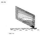
- FIGS. 9a and 9b illustrate the deformation distribution due to the twisting or distortion generated in the conventional door and the door of the present invention, respectively.
- the deformation in a right lower corner region is greater than those in the other regions.
- the reason is that a user generally grasps a lower portion of the handle 51 and pulls the handle 51 when he/she intends to open the door 50.
- the deformation in the right lower corner region of the door 50 corresponding to a side opposite to which the door 50 is connected is largest in a forward direction.
- deformation in the left upper corner region will be produced in a rearward direction by means of reaction thereto. Consequently, the deformation in the right lower corner region is largest.
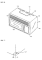
- an outer casing 140 defines a top surface and both side surfaces of the microwave oven.
- the outer casing 140 comprises a rectangular flat top portion 141 and side portions 143 that are bent almost perpendicularly from both longitudinal ends of the top portion 141.
- Chamfers 146 are formed at rear ends of edge portions where the top portion 141 and the side portions 143 intersect with each other.
- the chamfers 146 may be formed in the various manners: i.e., they may be formed directly on the outer casing 140 or formed by chamfering rear corners of the outer casing 140 and then welding additional chamfer pieces on the chamfered corners. In such a case, relevant portions of the cavity assembly or base plates (not shown) corresponding to the corners on which the chamfers 146 are formed should be manufactured to have a shape corresponding to inner portions of the chamfers 146.
- FIG. 11 shows an angle ⁇ that is formed by a line L extending along one of the external edges of the microwave oven and a border line of the chamfer 146 of the present invention when the chamfers 146 are formed on the outer casing 140.
- the angle ⁇ is within a range of 30 to 60 degrees. The reason is that if the angle is beyond the range of 30 to 60 degrees, excessively sharp edges are again formed.
- a door 150 for opening and closing a cooking chamber a control unit 160 for controlling the operation of the microwave oven, and a vent grille 170 for allowing air to flow into/from the microwave oven are provided at the front surface of the microwave oven according to an embodiment of the present invention.
- FIG. 12 shows an example of a microwave oven with shock-absorbing materials 180 mounted thereon for packaging the microwave oven of the present invention.
- the shock-absorbing materials 180 are mounted on the microwave oven and then secured into a packaging box so that an external impact or shock cannot be transmitted to the microwave oven.
- the chamfers 146 allow predetermined spaces to be defined between the shock-absorbing materials 180 and the corners of the microwave oven.
- the spaces function as a kind of shock-absorbing space, thereby remarkably reducing the shock or impact transmitted from the shock-absorbing materials 180 to the chamfers 146.
- portions of the shock-absorbing material 180 corresponding to the chamfers 146 may be shaped to be in close contact with the chamfers 146. Even in such a case, the shock or impact cannot be concentrated since the contact surface area between the shock-absorbing material 180 and each of the chamfers 146.
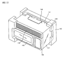
- FIGS. 13 to 16 show a large capacity microwave oven according to another example disclosing certain features of the present invention, wherein a lower end of a door of the microwave oven is hingedly connected to a cavity assembly and an upper end thereof is pivoted vertically on the hinged lower end so that a cooking chamber can be opened and closed.
- a cavity assembly 230 defines a framework of the microwave oven.
- a cooking chamber 231 for cooking the food therein is formed within the cavity assembly 230.
- an electronic equipment installation chamber in which various kinds of electronic equipment used for generating microwaves are installed is also provided at a side of the cavity assembly 230.
- a turntable 235 for allowing the food thereon to be turned and the microwaves to be uniformly transmitted to the food is provided in the cooking chamber 231.
- Latch slots 237 into which latches 257 to be explained later are inserted are formed at both sides on an upper front surface of the cavity assembly 230.
- An outer casing 240 is installed to enclose top and side faces of the cavity assembly 230.
- the outer casing 240 defines a top surface and both side surfaces of the microwave oven.
- a door 250 is installed at a front face of the cavity assembly 230.
- the door 250 functions to cause the cooking chamber 231 to be open and close.
- a lower end of the door 250 is hingedly connected to a front lower end of the cavity assembly 230.
- an upper end of the door 250 is pivoted on the lower end hingedly connected to the cavity assembly 230 so that the door 250 can cause the cooking chamber 231 to be open and close.
- a handle 251 is installed at a front upper end of the door 250, i.e. at a portion corresponding to a side opposite to which the door 250 is connected to the cavity assembly 230.
- the handle 251 is a part which a user grasps and applies a force to intend to open and close the door 250.
- a door panel 252 defines a front external appearance of the door 250.
- a structure through which the interior of the cooking chamber 231 can be viewed is provided at the center of the door panel 252.
- a door frame 254 is installed on a rear surface of the door panel 252.
- the door frame 254 functions as a framework of the door 250, and is generally formed to have a rectangular shape and a perforated central portion.
- the door frame 254 is provided with a supporting member 255 for connection with the door panel 252.
- the supporting member 255 is constructed to have a ' ⁇ ' shaped cross section.
- the latches 257 are provided at opposite ends of the rear surface of the door frame 254 to protrude from the rear surface. That is, when the door 250 is closed, the latches 257 are inserted into the latch slots 237 to prevent the door 150 from being inadvertently opened. Of course, the latches 257 also function to detect whether the door 250 is opened or closed.
- a choke cover 258 is further provided at the rear surface of the door frame 254 to prevent the leakage of microwaves.
- the choke cover 258 is formed to have a rectangular frame and functions to shield a choke structure that is formed to enclose the edge portions of the door frame 254.
- a reinforcing bar 259 is installed at the rear surface of the door panel 252.
- the reinforcing bar 259 is fastened to the door panel 252 and the door frame 254. That is, as shown in FIG. 15 , the reinforcing bar 259 is fastened to the door panel 252 and then the handle 251 through screws 259' and to the door frame 254 through screws 259".
- the reinforcing bar 259 is hooked over the supporting member 255.
- the reinforcing bar 259 is constructed to have a ' ⁇ ' shaped shaped cross section.
- the reinforcing bar 259 is formed to extend from side to side so that both ends thereof can be coupled to the opposite ends of the handle 251.
- the reinforcing bar 259 has a length as large as the length of the handle 251.
- the reinforcing bar 259 includes mounting portions 259m mounted to the door panel 252 at the both ends thereof and a linking portion 259c for linking the mounting portions 259m with each other.
- a plurality of coupling holes are formed in each of the mounting portions 259m.
- the reinforcing bar 259 is formed in such a manner that cross sections of the mounting portions 259m and the linking portion 259c are identical to one another. Therefore, the lengths of cross sections thereof are equal to one another.
- the rigidity of the door 250 can be enhanced as a whole.
- an external force is concentrated on the handle 251, whereby large deformation may be produced in the door 250. Consequently, the reinforcing bar 259 functions to improve the rigidity of the door 250 and thus to prevent the door from being deformed.
- FIG. 16 shows a modified example of a reinforcing bar according to the embodiment of the present invention.
- the reinforcing bar 359 of FIG. 16 includes mounting portions 359m fastened to the handle at both ends thereof and a linking portion 359c for linking the mounting portions 359m with each other.
- the mounting portions 359m and the linking portion 359c are formed to have different cross-sectional shapes. That is, the length of the cross section of the linking portion 359c is shorter than those of the mounting portions 359m. In other words, a surface area of the linking portion 359c is relatively small, i.e. smaller than that of the linking portion 259c of the reinforcing bar 259 shown in FIG. 14 .
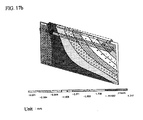
- FIGS. 17a and 17b illustrate deformation distribution in the door 250 due to twisting or distortion produced when the door 250 is opened or closed by using the handle 251 in cases where the reinforcing bar 259 is not employed in the door 250 according to the prior art and where the reinforcing bar 259 is incorporated into the door 250 according to the present invention, respectively.
- the convexo-concave reinforcements are formed along the upper end of the back plate in the example, the rigged reinforcements may be formed along entire edges of the back plate.
- the convexo-concave reinforcements are formed to have the same depths or heights as a whole, they may be formed to have different depths or heights. For example, in consideration of interference with or positional relationship between a variety of electronic equipment installed in the microwave oven, the convexo-concave reinforcements may be formed to have different depths or heights in accordance with their positions.
- the convexo-concave reinforcements formed on the side portions of the outer casing may be formed in such a manner that their depths or heights become smaller in the rearward direction. In such a case, convexo-concave reinforcements with almost no depth or height may be formed on rear ends of the side portions of the outer casing.
- the convexo-concave reinforcement for the back plate or only the convexo-concave reinforcement for the outer casing may be applied to the microwave oven. Only the door with the reinforcing plate incorporated therein may be applied to the microwave oven. Of course, the convexo-concave reinforcements may be applied to the back plate and the outer casing, respectively.
- the chamfers of FIG. 10 can be applied to the microwave oven shown in FIG. 2 .
- the chamfers may be applied to the microwave oven in combination with the structures for reinforcing the back plate, the outer casing, and the door.
- structural features for reinforcement of the outer casing or back plate may be simultaneously or selectively employed in the microwave oven shown in FIG. 13 .
- the outer casing, the back plate and the door for defining the external appearance of the microwave oven are strengthened, and the rigidity of the microwave oven is increased as a whole. Therefore, there is an advantage in that the deformation due to an impact or repeated use can be minimized.
- the present invention is configured in such a manner that the convexo-concave reinforcements and the chamfers are formed on the surface and the corners of the outer casing.
- the outer casing cannot be easily deformed even though the external force or impact is exerted on the outer casing.
- the present invention is configured in such a manner that the reinforcing plate is installed in the door at a side opposite to which the door is hingedly connected to the cavity assembly of the microwave oven to serve as a pivot center.
Landscapes
- Engineering & Computer Science (AREA)
- Physics & Mathematics (AREA)
- Electromagnetism (AREA)
- Chemical & Material Sciences (AREA)
- Combustion & Propulsion (AREA)
- Mechanical Engineering (AREA)
- General Engineering & Computer Science (AREA)
- Electric Ovens (AREA)
Claims (20)
- Ein Mikrowellenofen, mit:einer Hohlraumanordnung (30), die eine Garkammer (31) darin definiert und als ein Rahmen des Mikrowellenofens wirkt,einem Außengehäuse (40), das einen oberen Abschnitt (41) und Seitenabschnitte (43), welche an beiden Enden des oberen Abschnitts (41) ausgebildet sind, aufweist, um eine äußere Erscheinung des Mikrowellenofens durch Umschließen der Hohlraumanordnung (30) und von Innenteilen zu definieren,einer Tür (50), von der eine Seite mit der Hohlraumanordnung (30) als ein Schwenkzentrum verbunden ist und die ein Öffnen und Schließen der Garkammer (31) selektiv bewirkt, undeiner Rückplatte (33), die eine rückwärtige Fläche der Hohlraumanordnung (30) definiert,wobei die Rückplatte (33) mit einer konvexen-konkaven Verstärkung (33') entlang mindestens einem Randabschnitt derselben versehen ist,dadurch gekennzeichnet, dassAbschrägungen (146) an Ecken des Außengehäuses (140) ausgebildet sind, unddas Außengehäuse (40) mit konvexen-konkaven Verstärkungen (45) an dem oberen Abschnitt (41) und mindestens einem Seitenabschnitt (43) desselben versehen ist.
- Der Mikrowellenofen gemäß Anspruch 1, wobei die konvexe-konkave Verstärkung (33') der Rückplatte (33) horizontal an einem oberen Ende der Rückplatte (33) ausgebildet ist, welche an den oberen Abschnitt (41) des Außengehäuses (40) angrenzt.
- Der Mikrowellenofen gemäß Anspruch 2, wobei die Tiefe der konvexen-konkaven Verstärkung (33') der Rückplatte (33) in einem Bereich von 1 bis 8mm liegt.
- Der Mikrowellenofen gemäß Anspruch 1, 2 oder 3, wobei die konvexe-konkave Verstärkung (33') der Rückplatte (33) insgesamt gleichmäßig vorsteht oder vertieft ist.
- Der Mikrowellenofen gemäß Anspruch 3 oder 4, wobei eine zusätzliche konvexe-konkave Verstärkung (33'') in der Rückplatte (33) an einer Position angrenzend an ein durchgebohrtes Kabelloch (33h) ausgebildet ist.
- Der Mikrowellenofen gemäß Anspruch 5, wobei die zusätzliche konvexe-konkave Verstärkung (33'') rechteckig ist.
- Der Mikrowellenofen gemäß einem der Ansprüche 1 bis 6, wobei die konvexen-konkaven Verstärkungen (45) des Außengehäuses (40) an allen oberen und Seitenabschnitten (41,43) desselben ausgebildet sind.
- Der Mikrowellenofen gemäß einem der Ansprüche 1 bis 7, wobei eine Tiefe jeder der konvexen-konkaven Verstärkungen (45) des Außengehäuses (40) in einem Bereich von 0,5 bis 5mm liegt.
- Der Mikrowellenofen gemäß einem der Ansprüche 1 bis 8, wobei jede der konvexen-konkaven Verstärkungen (45) des Außengehäuses (40) mit derselben Tiefe über der Verstärkung (45) ausgebildet ist.
- Der Mikrowellenofen gemäß einem der Ansprüche 1 bis 8, wobei eine Tiefe der konvexen-konkaven Verstärkung (45) des Außengehäuses (40), die an dem Seitenabschnitt (43) des Außengehäuses (40) ausgebildet ist, in einer Richtung des Seitenabschnitts (43) nach unten kleiner wird.
- Der Mikrowellenofen gemäß einem der Ansprüche 1 bis 10, wobei die Abschrägungen (146) des Außengehäuses (140) durch Abtrennen der relevanten Ecken von dem Außengehäuse (140) und dann Anbringen zusätzlicher Platten an den abgeschnittenen Ecken gebildet sind.
- Der Mikrowellenofen gemäß einem der Ansprüche 1 bis 11, wobei ein Winkel (θ) zwischen einer Linie L, die sich entlang einer Außenkante des Außengehäuses (140) erstreckt, und ein Grenzlinie der Abschrägung (146) in einem Bereich von 30 bis 60 Grad liegt.
- Der Mikrowellenofen gemäß einem der Ansprüche 1 bis 12, wobei die Abschrägungen (146) nur an rückwärtigen Ecken des Außengehäuses (140) ausgebildet sind.
- Der Mikrowellenofen gemäß einem der Ansprüche 1 bis 13, wobei die Türe (50;250) aufweist:einen Türrahmen (54;254), der einen Rahmen der Türe (50;250) definiert,eine Türplatte (52;252), die an einer vorderen Oberfläche des Türrahmens (54;254) installiert ist, um eine äußere Erscheinung der Türe (50;250) zu definieren,einen Handgriff (51;251), der an der Türplatte (52;252) installiert ist und auf den eine Betätigungskraft zum Öffnen und Schließen der Tür (50;250) ausgeübt wird, undein Verstärkungselement (59;59';59";259;359), das an einer Seite gegenüber dem Schwenkzentrum angebracht ist, wo der Handgriff (51;251) vorgesehen ist.
- Der Mikrowellenofen gemäß Anspruch 14, wobei ein vorstehender Abschnitt (54a) und ein zurückgesetzter Abschnitt (54b) parallel entlang Kanten des Türrahmens (54) ausgebildet sind, und eine Drosselstruktur (56) zum Verhindern eines Austretens von Mikrowellen entlang Kanten einer rückwärtigen Oberfläche des Türrahmens (54) vorgesehen ist.
- Der Mikrowellenofen gemäß Anspruch 15, wobei das Verstärkungselement (59) mehrfach senkrecht zu einer Longitudinalrichtung desselben abgebogen ist, so dass es gleichzeitig an den vorstehenden und zurückgesetzten Abschnitten (54a,54b) angebracht werden kann.
- Der Mikrowellenofen gemäß Anspruch 15, wobei das Verstärkungselement (59') einmal senkrecht zu einer Longitudinalrichtung desselben abgebogen ist, so dass es an einer Oberfläche des vorstehenden Abschnitts (54a) und an einer Verbindungsfläche zwischen den vorstehenden und zurückgesetzten Abschnitten (54a,54b) angebracht werden kann.
- Der Mikrowellenofen gemäß Anspruch 15, wobei das Verstärkungselement (59") aus einer länglichen Platte mit einer vorbestimmten Breite entsprechend der des vorstehenden Abschnitts (54a) so ausgebildet ist, dass es an dem vorstehenden Abschnitt (54a) angebracht werden kann.
- Der Mikrowellenofen gemäß Anspruch 15, wobei das Verstärkungselement (259;359) an einer rückwärtigen Fläche der Türplatte (252) zur Verbindung mit dem Handgriff (251) angebracht ist und Befestigungsabschnitte (259m;359m), die an dem Handgriff (251) an beiden Enden desselben befestigt sind, und einen Verbindungsabschnitt (259c;359c) mit einer vorbestimmten Länge zum Verbinden der Befestigungsabschnitte (259m;359m) aufweist.
- Der Mikrowellenofen gemäß Anspruch 19, wobei eine Querschnittlänge des Verbindungsabschnitts (359c) des Verstärkungselements (359) kleiner ausgebildet ist, als diejenigen der Befestigungsabschnitte (359m).
Applications Claiming Priority (7)
| Application Number | Priority Date | Filing Date | Title |
|---|---|---|---|
| KR1020020087830A KR20040061559A (ko) | 2002-12-31 | 2002-12-31 | 모서리부가 강화된 전자레인지 |
| KR2002087830 | 2002-12-31 | ||
| KR2003000632 | 2003-01-06 | ||
| KR1020030000632A KR20040063276A (ko) | 2003-01-06 | 2003-01-06 | 전자레인지의 도어구조 |
| KR1020030000633A KR20040063277A (ko) | 2003-01-06 | 2003-01-06 | 전자레인지의 도어구조 |
| KR2003000633 | 2003-01-06 | ||
| PCT/KR2003/002702 WO2004059213A1 (en) | 2002-12-31 | 2003-12-10 | Microwave oven |
Publications (3)
| Publication Number | Publication Date |
|---|---|
| EP1579152A1 EP1579152A1 (de) | 2005-09-28 |
| EP1579152A4 EP1579152A4 (de) | 2008-05-07 |
| EP1579152B1 true EP1579152B1 (de) | 2012-07-04 |
Family
ID=36566426
Family Applications (1)
| Application Number | Title | Priority Date | Filing Date |
|---|---|---|---|
| EP03813987A Expired - Lifetime EP1579152B1 (de) | 2002-12-31 | 2003-12-10 | Mikrowellenofen |
Country Status (4)
| Country | Link |
|---|---|
| US (2) | US7012230B2 (de) |
| EP (1) | EP1579152B1 (de) |
| AU (1) | AU2003303357A1 (de) |
| WO (1) | WO2004059213A1 (de) |
Families Citing this family (8)
| Publication number | Priority date | Publication date | Assignee | Title |
|---|---|---|---|---|
| USD518681S1 (en) * | 2004-03-23 | 2006-04-11 | Lg Electronics Inc. | Microwave oven |
| US8405010B2 (en) * | 2007-11-06 | 2013-03-26 | Bryan J. Van Dyke | Portable microwave oven with protective frame |
| CN110842091B (zh) * | 2019-11-05 | 2024-07-05 | 苏州托克斯冲压设备有限公司 | 微波炉面板咬合装置 |
| US11692716B2 (en) | 2020-05-15 | 2023-07-04 | Electrolux Home Products, Inc. | Housing for household appliance with external panel having integrated reinforcement |
| US20220304121A1 (en) * | 2021-03-19 | 2022-09-22 | Midea Group Co., Ltd. | Microwave cooking appliance with power management |
| US12382554B2 (en) | 2021-03-19 | 2025-08-05 | Midea Group Co., Ltd. | Microwave cooking appliance with retracting power management |
| EP4386114A4 (de) * | 2021-10-12 | 2025-06-11 | Samsung Electronics Co., Ltd. | Aussenplatte für haushaltsgerät, haushaltsgerät damit und aussenplattenherstellungsverfahren |
| WO2023232091A1 (zh) * | 2022-06-01 | 2023-12-07 | 广东美的厨房电器制造有限公司 | 门体组件和烹饪器具 |
Family Cites Families (18)
| Publication number | Priority date | Publication date | Assignee | Title |
|---|---|---|---|---|
| JPS52140449U (de) * | 1976-04-20 | 1977-10-25 | ||
| JPS5850172Y2 (ja) * | 1978-02-09 | 1983-11-15 | 松下電器産業株式会社 | 調理器 |
| GB2104645B (en) * | 1981-07-03 | 1985-02-20 | Ti Domestic Appliances Ltd | Improvements in or relating to cookers |
| US4679416A (en) * | 1984-08-06 | 1987-07-14 | R. R. Brink Locking Systems, Inc. | Trigger and latch bolt assembly |
| AU590528B2 (en) * | 1984-11-20 | 1989-11-09 | Matsushita Electric Industrial Co., Ltd. | Door assembly for microwave heating apparatus |
| JP2614336B2 (ja) * | 1989-11-24 | 1997-05-28 | 株式会社東芝 | 高周波加熱調理装置 |
| KR960003106Y1 (ko) * | 1993-10-30 | 1996-04-16 | 대우전자 주식회사 | 전자렌지의 캐비티(cavity) 보강구조 |
| KR950019405A (ko) | 1993-12-04 | 1995-07-24 | 이헌조 | 전자레인지 오븐캐비티의 보호장치 |
| JP2916441B2 (ja) | 1996-04-23 | 1999-07-05 | 三星電子株式会社 | 電子レンジ |
| US6572830B1 (en) * | 1998-10-09 | 2003-06-03 | Motorola, Inc. | Integrated multilayered microfludic devices and methods for making the same |
| KR100389441B1 (ko) * | 1999-12-27 | 2003-06-27 | 주식회사 엘지이아이 | 빌트인타입 전자레인지 |
| AU2868701A (en) * | 2000-02-02 | 2001-08-14 | Apollo Usa Inc. | Microwave ovens and sub-assemblies therefor |
| US6295198B1 (en) * | 2000-03-07 | 2001-09-25 | Hewlett-Packard Company | Computer device |
| DE10049847B4 (de) * | 2000-04-19 | 2005-12-01 | Lg Electronics Inc. | Mikrowellenherd |
| KR100381418B1 (ko) * | 2000-10-26 | 2003-04-26 | 삼성전자주식회사 | 벽걸이형 전자렌지 |
| KR200229365Y1 (ko) * | 2000-12-28 | 2001-07-19 | 엘지전자 주식회사 | 전자레인지의 장착플레이트 장착구조 |
| US6747255B2 (en) * | 2002-03-21 | 2004-06-08 | Samsung Electronics Co., Ltd. | Microwave oven with increased usable space |
| US6759638B2 (en) * | 2002-08-13 | 2004-07-06 | Samsung Electronics Co., Ltd. | Microwave oven having a projecting door and cooking cavity |
-
2003
- 2003-12-10 EP EP03813987A patent/EP1579152B1/de not_active Expired - Lifetime
- 2003-12-10 WO PCT/KR2003/002702 patent/WO2004059213A1/en not_active Ceased
- 2003-12-10 AU AU2003303357A patent/AU2003303357A1/en not_active Abandoned
- 2003-12-23 US US10/742,875 patent/US7012230B2/en not_active Expired - Fee Related
-
2006
- 2006-01-05 US US11/325,435 patent/US7645967B2/en not_active Expired - Fee Related
Also Published As
| Publication number | Publication date |
|---|---|
| WO2004059213A1 (en) | 2004-07-15 |
| EP1579152A1 (de) | 2005-09-28 |
| US20040178195A1 (en) | 2004-09-16 |
| US7645967B2 (en) | 2010-01-12 |
| US7012230B2 (en) | 2006-03-14 |
| US20060113301A1 (en) | 2006-06-01 |
| EP1579152A4 (de) | 2008-05-07 |
| AU2003303357A1 (en) | 2004-07-22 |
Similar Documents
| Publication | Publication Date | Title |
|---|---|---|
| EP1579152B1 (de) | Mikrowellenofen | |
| KR100233437B1 (ko) | 전자렌지의 도어 | |
| US6940057B2 (en) | Microwave oven | |
| US20030230571A1 (en) | Wall-mounted type microwave oven | |
| CN100378404C (zh) | 微波炉 | |
| KR100609174B1 (ko) | 전자레인지의 베이스 플레이트 구조 | |
| KR100614312B1 (ko) | 전자레인지의 아웃케이스 | |
| CN219661505U (zh) | 防护网和烹饪设备 | |
| KR100485575B1 (ko) | 전자렌지 | |
| KR100270866B1 (ko) | 전자렌지의캐비닛변형방지구조 | |
| KR100646894B1 (ko) | 전자레인지의 힌지어셈블리구조 | |
| KR0137170Y1 (ko) | 전자렌지의 도어용 힌지 조립체 | |
| EP2026633A2 (de) | Gargerät | |
| KR100712279B1 (ko) | 전자렌지 도어의 쵸크 변형 방지 구조 | |
| KR20040063277A (ko) | 전자레인지의 도어구조 | |
| KR100796367B1 (ko) | 조리기의 캐비티 | |
| KR200329721Y1 (ko) | 전자레인지의 프론트 플레이트 | |
| KR200337673Y1 (ko) | 전자레인지 스테인리스카바의 접지구조 | |
| KR200386253Y1 (ko) | 후드겸용 전자레인지 | |
| KR100513300B1 (ko) | 전자렌지 | |
| KR200337672Y1 (ko) | 전자레인지 스테인리스카바의 고정구조 | |
| KR20050002124A (ko) | 다각도로 투시가능한 캐비티를 가진 전자 레인지 | |
| KR200162048Y1 (ko) | 전자렌지용 패널의 결합부 구조 | |
| KR200302297Y1 (ko) | 전자렌지 | |
| CN120616336A (zh) | 一种双层组合微波烤箱 |
Legal Events
| Date | Code | Title | Description |
|---|---|---|---|
| PUAI | Public reference made under article 153(3) epc to a published international application that has entered the european phase |
Free format text: ORIGINAL CODE: 0009012 |
|
| 17P | Request for examination filed |
Effective date: 20040819 |
|
| AK | Designated contracting states |
Kind code of ref document: A1 Designated state(s): AT BE BG CH CY CZ DE DK EE ES FI FR GB GR HU IE IT LI LU MC NL PT RO SE SI SK TR |
|
| AX | Request for extension of the european patent |
Extension state: AL LT LV MK |
|
| DAX | Request for extension of the european patent (deleted) | ||
| RBV | Designated contracting states (corrected) |
Designated state(s): DE FR GB IT |
|
| A4 | Supplementary search report drawn up and despatched |
Effective date: 20080403 |
|
| 17Q | First examination report despatched |
Effective date: 20090629 |
|
| REG | Reference to a national code |
Ref country code: DE Ref legal event code: R079 Ref document number: 60341469 Country of ref document: DE Free format text: PREVIOUS MAIN CLASS: F24C0015080000 Ipc: H05B0006640000 |
|
| GRAP | Despatch of communication of intention to grant a patent |
Free format text: ORIGINAL CODE: EPIDOSNIGR1 |
|
| RIC1 | Information provided on ipc code assigned before grant |
Ipc: H05B 6/64 20060101AFI20120109BHEP Ipc: F24C 15/08 20060101ALI20120109BHEP |
|
| GRAS | Grant fee paid |
Free format text: ORIGINAL CODE: EPIDOSNIGR3 |
|
| GRAA | (expected) grant |
Free format text: ORIGINAL CODE: 0009210 |
|
| AK | Designated contracting states |
Kind code of ref document: B1 Designated state(s): DE FR GB IT |
|
| REG | Reference to a national code |
Ref country code: GB Ref legal event code: FG4D |
|
| REG | Reference to a national code |
Ref country code: DE Ref legal event code: R096 Ref document number: 60341469 Country of ref document: DE Effective date: 20120830 |
|
| PLBE | No opposition filed within time limit |
Free format text: ORIGINAL CODE: 0009261 |
|
| STAA | Information on the status of an ep patent application or granted ep patent |
Free format text: STATUS: NO OPPOSITION FILED WITHIN TIME LIMIT |
|
| PG25 | Lapsed in a contracting state [announced via postgrant information from national office to epo] |
Ref country code: IT Free format text: LAPSE BECAUSE OF FAILURE TO SUBMIT A TRANSLATION OF THE DESCRIPTION OR TO PAY THE FEE WITHIN THE PRESCRIBED TIME-LIMIT Effective date: 20120704 |
|
| 26N | No opposition filed |
Effective date: 20130405 |
|
| REG | Reference to a national code |
Ref country code: DE Ref legal event code: R097 Ref document number: 60341469 Country of ref document: DE Effective date: 20130405 |
|
| PGFP | Annual fee paid to national office [announced via postgrant information from national office to epo] |
Ref country code: FR Payment date: 20141111 Year of fee payment: 12 |
|
| REG | Reference to a national code |
Ref country code: FR Ref legal event code: ST Effective date: 20160831 |
|
| PG25 | Lapsed in a contracting state [announced via postgrant information from national office to epo] |
Ref country code: FR Free format text: LAPSE BECAUSE OF NON-PAYMENT OF DUE FEES Effective date: 20151231 |
|
| PGFP | Annual fee paid to national office [announced via postgrant information from national office to epo] |
Ref country code: DE Payment date: 20171107 Year of fee payment: 15 |
|
| PGFP | Annual fee paid to national office [announced via postgrant information from national office to epo] |
Ref country code: GB Payment date: 20171107 Year of fee payment: 15 |
|
| REG | Reference to a national code |
Ref country code: DE Ref legal event code: R119 Ref document number: 60341469 Country of ref document: DE |
|
| GBPC | Gb: european patent ceased through non-payment of renewal fee |
Effective date: 20181210 |
|
| PG25 | Lapsed in a contracting state [announced via postgrant information from national office to epo] |
Ref country code: DE Free format text: LAPSE BECAUSE OF NON-PAYMENT OF DUE FEES Effective date: 20190702 |
|
| PG25 | Lapsed in a contracting state [announced via postgrant information from national office to epo] |
Ref country code: GB Free format text: LAPSE BECAUSE OF NON-PAYMENT OF DUE FEES Effective date: 20181210 |