EP1579036B1 - Vorrichtung und verfahren zum trockenen entfernen von zunder auf der oberfläche von metallprodukten - Google Patents
Vorrichtung und verfahren zum trockenen entfernen von zunder auf der oberfläche von metallprodukten Download PDFInfo
- Publication number
- EP1579036B1 EP1579036B1 EP03767550A EP03767550A EP1579036B1 EP 1579036 B1 EP1579036 B1 EP 1579036B1 EP 03767550 A EP03767550 A EP 03767550A EP 03767550 A EP03767550 A EP 03767550A EP 1579036 B1 EP1579036 B1 EP 1579036B1
- Authority
- EP
- European Patent Office
- Prior art keywords
- heating
- metal product
- reducing gas
- scale
- reaction
- Prior art date
- Legal status (The legal status is an assumption and is not a legal conclusion. Google has not performed a legal analysis and makes no representation as to the accuracy of the status listed.)
- Expired - Lifetime
Links
- 229910052751 metal Inorganic materials 0.000 title claims abstract description 140
- 239000002184 metal Substances 0.000 title claims abstract description 140
- 238000000034 method Methods 0.000 title claims abstract description 128
- 230000008569 process Effects 0.000 title claims abstract description 120
- 239000007789 gas Substances 0.000 claims abstract description 173
- 239000000047 product Substances 0.000 claims abstract description 157
- 238000010438 heat treatment Methods 0.000 claims abstract description 109
- 238000006243 chemical reaction Methods 0.000 claims abstract description 67
- 239000007795 chemical reaction product Substances 0.000 claims abstract description 37
- 238000001816 cooling Methods 0.000 claims abstract description 27
- UFHFLCQGNIYNRP-UHFFFAOYSA-N Hydrogen Chemical compound [H][H] UFHFLCQGNIYNRP-UHFFFAOYSA-N 0.000 claims abstract description 25
- 239000001257 hydrogen Substances 0.000 claims abstract description 25
- 229910052739 hydrogen Inorganic materials 0.000 claims abstract description 25
- 239000012530 fluid Substances 0.000 claims abstract description 19
- 239000000463 material Substances 0.000 claims abstract description 17
- 238000005554 pickling Methods 0.000 claims description 54
- XLYOFNOQVPJJNP-UHFFFAOYSA-N water Chemical compound O XLYOFNOQVPJJNP-UHFFFAOYSA-N 0.000 claims description 37
- QVGXLLKOCUKJST-UHFFFAOYSA-N atomic oxygen Chemical compound [O] QVGXLLKOCUKJST-UHFFFAOYSA-N 0.000 claims description 19
- 239000001301 oxygen Substances 0.000 claims description 19
- 229910052760 oxygen Inorganic materials 0.000 claims description 19
- 230000006698 induction Effects 0.000 claims description 14
- 230000005855 radiation Effects 0.000 claims description 13
- 230000001680 brushing effect Effects 0.000 claims description 12
- 230000010355 oscillation Effects 0.000 claims description 12
- 239000000126 substance Substances 0.000 claims description 12
- 238000007664 blowing Methods 0.000 claims description 9
- 229910044991 metal oxide Inorganic materials 0.000 claims description 9
- 150000004706 metal oxides Chemical class 0.000 claims description 9
- XKRFYHLGVUSROY-UHFFFAOYSA-N Argon Chemical compound [Ar] XKRFYHLGVUSROY-UHFFFAOYSA-N 0.000 claims description 8
- IJGRMHOSHXDMSA-UHFFFAOYSA-N Atomic nitrogen Chemical compound N#N IJGRMHOSHXDMSA-UHFFFAOYSA-N 0.000 claims description 8
- 230000000694 effects Effects 0.000 claims description 8
- 238000011282 treatment Methods 0.000 claims description 7
- 238000009826 distribution Methods 0.000 claims description 6
- 239000000203 mixture Substances 0.000 claims description 6
- 230000001590 oxidative effect Effects 0.000 claims description 5
- 238000004064 recycling Methods 0.000 claims description 5
- 238000010521 absorption reaction Methods 0.000 claims description 4
- 229910052786 argon Inorganic materials 0.000 claims description 4
- 229910052757 nitrogen Inorganic materials 0.000 claims description 4
- 239000011819 refractory material Substances 0.000 claims description 4
- 239000001307 helium Substances 0.000 claims description 3
- 229910052734 helium Inorganic materials 0.000 claims description 3
- SWQJXJOGLNCZEY-UHFFFAOYSA-N helium atom Chemical compound [He] SWQJXJOGLNCZEY-UHFFFAOYSA-N 0.000 claims description 3
- 238000010926 purge Methods 0.000 claims description 2
- 230000035484 reaction time Effects 0.000 claims description 2
- 239000011261 inert gas Substances 0.000 claims 2
- 230000003647 oxidation Effects 0.000 abstract description 8
- 238000007254 oxidation reaction Methods 0.000 abstract description 8
- XEEYBQQBJWHFJM-UHFFFAOYSA-N Iron Chemical compound [Fe] XEEYBQQBJWHFJM-UHFFFAOYSA-N 0.000 description 52
- 238000006722 reduction reaction Methods 0.000 description 43
- 230000009467 reduction Effects 0.000 description 35
- UQSXHKLRYXJYBZ-UHFFFAOYSA-N iron oxide Inorganic materials [Fe]=O UQSXHKLRYXJYBZ-UHFFFAOYSA-N 0.000 description 29
- 229910052742 iron Inorganic materials 0.000 description 25
- 239000002253 acid Substances 0.000 description 23
- 239000012071 phase Substances 0.000 description 21
- 238000009792 diffusion process Methods 0.000 description 17
- SZVJSHCCFOBDDC-UHFFFAOYSA-N ferrosoferric oxide Chemical compound O=[Fe]O[Fe]O[Fe]=O SZVJSHCCFOBDDC-UHFFFAOYSA-N 0.000 description 17
- JEIPFZHSYJVQDO-UHFFFAOYSA-N iron(III) oxide Inorganic materials O=[Fe]O[Fe]=O JEIPFZHSYJVQDO-UHFFFAOYSA-N 0.000 description 13
- 230000002829 reductive effect Effects 0.000 description 12
- 239000007787 solid Substances 0.000 description 12
- 229910000831 Steel Inorganic materials 0.000 description 9
- 230000008901 benefit Effects 0.000 description 9
- 239000010959 steel Substances 0.000 description 9
- 230000009471 action Effects 0.000 description 7
- 238000007791 dehumidification Methods 0.000 description 7
- 238000004519 manufacturing process Methods 0.000 description 7
- 239000000243 solution Substances 0.000 description 7
- 230000015572 biosynthetic process Effects 0.000 description 5
- 229910002091 carbon monoxide Inorganic materials 0.000 description 5
- 239000003153 chemical reaction reagent Substances 0.000 description 5
- 238000002347 injection Methods 0.000 description 5
- 239000007924 injection Substances 0.000 description 5
- 235000013980 iron oxide Nutrition 0.000 description 5
- VBMVTYDPPZVILR-UHFFFAOYSA-N iron(2+);oxygen(2-) Chemical class [O-2].[Fe+2] VBMVTYDPPZVILR-UHFFFAOYSA-N 0.000 description 5
- 239000007788 liquid Substances 0.000 description 5
- VNWKTOKETHGBQD-UHFFFAOYSA-N methane Chemical compound C VNWKTOKETHGBQD-UHFFFAOYSA-N 0.000 description 5
- 230000007935 neutral effect Effects 0.000 description 5
- 230000009257 reactivity Effects 0.000 description 5
- UGFAIRIUMAVXCW-UHFFFAOYSA-N Carbon monoxide Chemical compound [O+]#[C-] UGFAIRIUMAVXCW-UHFFFAOYSA-N 0.000 description 4
- 229910052799 carbon Inorganic materials 0.000 description 4
- 238000011946 reduction process Methods 0.000 description 4
- 238000005096 rolling process Methods 0.000 description 4
- 150000003839 salts Chemical class 0.000 description 4
- 238000012360 testing method Methods 0.000 description 4
- VEXZGXHMUGYJMC-UHFFFAOYSA-N Hydrochloric acid Chemical compound Cl VEXZGXHMUGYJMC-UHFFFAOYSA-N 0.000 description 3
- QAOWNCQODCNURD-UHFFFAOYSA-N Sulfuric acid Chemical compound OS(O)(=O)=O QAOWNCQODCNURD-UHFFFAOYSA-N 0.000 description 3
- 238000002485 combustion reaction Methods 0.000 description 3
- 230000005611 electricity Effects 0.000 description 3
- 230000007246 mechanism Effects 0.000 description 3
- 230000009466 transformation Effects 0.000 description 3
- CWYNVVGOOAEACU-UHFFFAOYSA-N Fe2+ Chemical compound [Fe+2] CWYNVVGOOAEACU-UHFFFAOYSA-N 0.000 description 2
- 229910002588 FeOOH Inorganic materials 0.000 description 2
- VYPSYNLAJGMNEJ-UHFFFAOYSA-N Silicium dioxide Chemical compound O=[Si]=O VYPSYNLAJGMNEJ-UHFFFAOYSA-N 0.000 description 2
- 238000004140 cleaning Methods 0.000 description 2
- 238000005260 corrosion Methods 0.000 description 2
- 230000007797 corrosion Effects 0.000 description 2
- 238000010586 diagram Methods 0.000 description 2
- 238000001035 drying Methods 0.000 description 2
- 230000008030 elimination Effects 0.000 description 2
- 238000003379 elimination reaction Methods 0.000 description 2
- 230000007613 environmental effect Effects 0.000 description 2
- 239000003112 inhibitor Substances 0.000 description 2
- 229910052500 inorganic mineral Inorganic materials 0.000 description 2
- BAUYGSIQEAFULO-UHFFFAOYSA-L iron(2+) sulfate (anhydrous) Chemical compound [Fe+2].[O-]S([O-])(=O)=O BAUYGSIQEAFULO-UHFFFAOYSA-L 0.000 description 2
- FLTRNWIFKITPIO-UHFFFAOYSA-N iron;trihydrate Chemical compound O.O.O.[Fe] FLTRNWIFKITPIO-UHFFFAOYSA-N 0.000 description 2
- 238000003754 machining Methods 0.000 description 2
- 239000011707 mineral Substances 0.000 description 2
- 239000003345 natural gas Substances 0.000 description 2
- 230000036961 partial effect Effects 0.000 description 2
- 239000000376 reactant Substances 0.000 description 2
- 238000001179 sorption measurement Methods 0.000 description 2
- 239000001117 sulphuric acid Substances 0.000 description 2
- 235000011149 sulphuric acid Nutrition 0.000 description 2
- 229910000851 Alloy steel Inorganic materials 0.000 description 1
- OKTJSMMVPCPJKN-UHFFFAOYSA-N Carbon Chemical compound [C] OKTJSMMVPCPJKN-UHFFFAOYSA-N 0.000 description 1
- 229910000640 Fe alloy Inorganic materials 0.000 description 1
- 239000005569 Iron sulphate Substances 0.000 description 1
- KKCBUQHMOMHUOY-UHFFFAOYSA-N Na2O Inorganic materials [O-2].[Na+].[Na+] KKCBUQHMOMHUOY-UHFFFAOYSA-N 0.000 description 1
- 238000005270 abrasive blasting Methods 0.000 description 1
- 239000006096 absorbing agent Substances 0.000 description 1
- 238000009825 accumulation Methods 0.000 description 1
- 150000007513 acids Chemical class 0.000 description 1
- 239000000853 adhesive Substances 0.000 description 1
- 230000001070 adhesive effect Effects 0.000 description 1
- 238000005275 alloying Methods 0.000 description 1
- 238000004458 analytical method Methods 0.000 description 1
- 238000005452 bending Methods 0.000 description 1
- 230000000903 blocking effect Effects 0.000 description 1
- 230000008859 change Effects 0.000 description 1
- 230000000739 chaotic effect Effects 0.000 description 1
- 230000002925 chemical effect Effects 0.000 description 1
- 229910052681 coesite Inorganic materials 0.000 description 1
- 238000010276 construction Methods 0.000 description 1
- 239000000112 cooling gas Substances 0.000 description 1
- 229910052906 cristobalite Inorganic materials 0.000 description 1
- 238000000354 decomposition reaction Methods 0.000 description 1
- 238000003795 desorption Methods 0.000 description 1
- 238000010494 dissociation reaction Methods 0.000 description 1
- 230000005593 dissociations Effects 0.000 description 1
- 238000005516 engineering process Methods 0.000 description 1
- 238000004880 explosion Methods 0.000 description 1
- 239000003517 fume Substances 0.000 description 1
- 239000007792 gaseous phase Substances 0.000 description 1
- 239000011019 hematite Substances 0.000 description 1
- 229930195733 hydrocarbon Natural products 0.000 description 1
- 230000006872 improvement Effects 0.000 description 1
- 239000012535 impurity Substances 0.000 description 1
- 150000002500 ions Chemical class 0.000 description 1
- 235000014413 iron hydroxide Nutrition 0.000 description 1
- 229910000359 iron(II) sulfate Inorganic materials 0.000 description 1
- NCNCGGDMXMBVIA-UHFFFAOYSA-L iron(ii) hydroxide Chemical class [OH-].[OH-].[Fe+2] NCNCGGDMXMBVIA-UHFFFAOYSA-L 0.000 description 1
- 230000001788 irregular Effects 0.000 description 1
- 238000003475 lamination Methods 0.000 description 1
- 230000000670 limiting effect Effects 0.000 description 1
- 238000007726 management method Methods 0.000 description 1
- 238000010297 mechanical methods and process Methods 0.000 description 1
- 239000007769 metal material Substances 0.000 description 1
- 238000002156 mixing Methods 0.000 description 1
- 230000004660 morphological change Effects 0.000 description 1
- -1 nitrogenous hydrocarbons Chemical class 0.000 description 1
- 239000003921 oil Substances 0.000 description 1
- 238000005457 optimization Methods 0.000 description 1
- 238000013021 overheating Methods 0.000 description 1
- 230000000149 penetrating effect Effects 0.000 description 1
- 230000035515 penetration Effects 0.000 description 1
- 230000000737 periodic effect Effects 0.000 description 1
- 239000011148 porous material Substances 0.000 description 1
- 238000012545 processing Methods 0.000 description 1
- 239000011253 protective coating Substances 0.000 description 1
- 230000001681 protective effect Effects 0.000 description 1
- 239000012495 reaction gas Substances 0.000 description 1
- 238000011084 recovery Methods 0.000 description 1
- 238000010405 reoxidation reaction Methods 0.000 description 1
- 238000005488 sandblasting Methods 0.000 description 1
- 229920006395 saturated elastomer Polymers 0.000 description 1
- 238000009738 saturating Methods 0.000 description 1
- 238000005480 shot peening Methods 0.000 description 1
- 239000000377 silicon dioxide Substances 0.000 description 1
- 230000003068 static effect Effects 0.000 description 1
- 229910052682 stishovite Inorganic materials 0.000 description 1
- 239000000758 substrate Substances 0.000 description 1
- 239000002341 toxic gas Substances 0.000 description 1
- 239000010891 toxic waste Substances 0.000 description 1
- 238000012546 transfer Methods 0.000 description 1
- 230000001052 transient effect Effects 0.000 description 1
- 229910052905 tridymite Inorganic materials 0.000 description 1
- 238000002604 ultrasonography Methods 0.000 description 1
- 239000002699 waste material Substances 0.000 description 1
- 238000004804 winding Methods 0.000 description 1
Images


Classifications
-
- C—CHEMISTRY; METALLURGY
- C23—COATING METALLIC MATERIAL; COATING MATERIAL WITH METALLIC MATERIAL; CHEMICAL SURFACE TREATMENT; DIFFUSION TREATMENT OF METALLIC MATERIAL; COATING BY VACUUM EVAPORATION, BY SPUTTERING, BY ION IMPLANTATION OR BY CHEMICAL VAPOUR DEPOSITION, IN GENERAL; INHIBITING CORROSION OF METALLIC MATERIAL OR INCRUSTATION IN GENERAL
- C23G—CLEANING OR DE-GREASING OF METALLIC MATERIAL BY CHEMICAL METHODS OTHER THAN ELECTROLYSIS
- C23G5/00—Cleaning or de-greasing metallic material by other methods; Apparatus for cleaning or de-greasing metallic material with organic solvents
-
- B—PERFORMING OPERATIONS; TRANSPORTING
- B08—CLEANING
- B08B—CLEANING IN GENERAL; PREVENTION OF FOULING IN GENERAL
- B08B7/00—Cleaning by methods not provided for in a single other subclass or a single group in this subclass
-
- B—PERFORMING OPERATIONS; TRANSPORTING
- B21—MECHANICAL METAL-WORKING WITHOUT ESSENTIALLY REMOVING MATERIAL; PUNCHING METAL
- B21B—ROLLING OF METAL
- B21B45/00—Devices for surface or other treatment of work, specially combined with or arranged in, or specially adapted for use in connection with, metal-rolling mills
- B21B45/004—Heating the product
- B21B2045/006—Heating the product in vacuum or in inert atmosphere
-
- B—PERFORMING OPERATIONS; TRANSPORTING
- B21—MECHANICAL METAL-WORKING WITHOUT ESSENTIALLY REMOVING MATERIAL; PUNCHING METAL
- B21B—ROLLING OF METAL
- B21B45/00—Devices for surface or other treatment of work, specially combined with or arranged in, or specially adapted for use in connection with, metal-rolling mills
- B21B45/004—Heating the product
-
- B—PERFORMING OPERATIONS; TRANSPORTING
- B21—MECHANICAL METAL-WORKING WITHOUT ESSENTIALLY REMOVING MATERIAL; PUNCHING METAL
- B21B—ROLLING OF METAL
- B21B45/00—Devices for surface or other treatment of work, specially combined with or arranged in, or specially adapted for use in connection with, metal-rolling mills
- B21B45/04—Devices for surface or other treatment of work, specially combined with or arranged in, or specially adapted for use in connection with, metal-rolling mills for de-scaling, e.g. by brushing
Definitions
- This invention relates to an apparatus and a process for the dry removal of the scale found on the surface of metal products. More particularly, it relates to an apparatus and process for treating metal products in the shape of bars, strips, or other types of iron and steel products.
- steel oxidation is also affected by the behaviour of the elements found in the steel alloy.
- surface scale found on steel products is typically formed by iron oxides and always contains FeO (also called wustite), Fe 3 O 4 (also called magnetite), Fe 2 O 3 (also called haematite), and Fe(OH) 3 or FeOOH (also called rust or limonite).
- FeO also called wustite
- Fe 3 O 4 also called magnetite
- Fe 2 O 3 also called haematite
- Fe(OH) 3 or FeOOH also called rust or limonite
- Fe 2 O 3 are present; while, above said temperature, an internal layer of FeO is formed along with the two oxides.
- an internal layer of FeO is formed along with the two oxides.
- the presence of other elements leads to structural changes in the scale and affects the growth kinetics of the scale.
- the underlying metal is modified due to the phenomenon of selective oxidation of this binding additional material.
- oxidized products are exposed for prolonged periods of time to industrial and/or sea air. This, leads to considerable rusting (thick layers of complex iron hydroxides (millimetres). Therefore the products to be pickled can appear like material coated by a dark grey layer, e.g. black strip, made of mixed oxides, whose thickness is comprised between fractions of ⁇ m and 10 ⁇ m maximum.
- a dark grey layer e.g. black strip
- this kind of scale is the easiest to be removed. It is more difficult to remove the scale from materials having been subject to corrosion so as to produce a thick layer of oxides or very deep cavities, even in the range from 50 to 100 ⁇ m.
- the most widely used process for removing scale from metal products is pickling with acid; this process involves treating the metal products with H 2 SO 4 or HCl at a temperature of approximately 80°C for a period of time ranging from 10 to 30 minutes.
- the metal is normally cleaned by immersing the coils in a container filled with hot hydrochloric or sulphuric acid.
- Sulphuric acid mainly eliminates scale by means of a mechanical, rather than chemical, action.
- the acid is able to penetrate into the metal under the scale layer where it reacts with the iron forming water-soluble iron sulphate and releasing a gas mixture consisting mainly of H 2 .
- This action detaches the scale from the iron; then, at the end of the pickling process with acid, the surfaces of the metal product are cleaned with highpressure jets of water.
- Temperature control plays an important role in this type of pickling since the speed of the acid-metal reaction is highly affected by temperature; for example, the reaction is 100 times faster at 88°C than at ambient temperature.
- overheating the acid wastes energy consumes an excessive amount of acid very quickly, and creates unnecessary fumes that are highly corrosive to the structure of the plant
- acid at high temperatures is also damaging to the surface of the metal: it produces pitting.
- inhibitors are commonly used. Said inhibitors are products based on nitrogenous hydrocarbons. The time required to clean the metal product varies depending on the type of scale to be eliminated and the type of metal to be treated. This can range from 10 minutes for bars with a high-carbon content to 35 minutes for bars with a low-carbon content and a considerable amount of scale. For this reason, pickling with acid is most suited for metal surfaces covered with a thin scale layer.
- the metal product pickled with acid is rinsed and covered with a protective coating.
- the main drawback of using the acid pickling method is the significant negative environmental impact and the reduced kinetics of the reaction.
- the acid residues found in the acid baths are potentially dangerous; handling, disposing of, an storing these products is complex and costly.
- efficiency can fall to below 33%.
- Another commonly used method is mechanical descaling; this, can be done through bending, shot peening, sand blasting, brushing, or using ultrasounds. Once again, the purpose of these methods is to detach, remove, or break off mechanically the scale layer.
- Mechanical descaling is more effective on fragile scale with low adherence to the metal product; thus, mechanical descaling is more appropriate for thick layers of the scale since, the thicker the scale layer, the lower its bond to the metal.
- K 2 O (Na 2 O, SiO 2 ) based salts are able to dissolve iron oxides and produce two immiscible liquids.
- the liquid with the highest content of FeO can be regenerated.
- the regenerated salt will be reutilized for pickling.
- the scale is washed with a liquid and the acid is replaced by a bath of dissolved salts.
- the main inputs are, respectively, electricity only or electricity, N 2 , H 2 , and air-CH 4 , the last item is used when the furnace is also equipped with natural gas burners.
- the products leaving the plant are water vapor and H 2 and, in the case of a furnace equipped with gas burners, also the combustion products of natural gas.
- Acid-free pickling has many advantages over pickling with acid including the absence of dangerous toxic waste, the absence of corrosion on the metal surface, and the use of mildly aggressive cleaning means.
- fans to recycle the reducing gas inside the reactor can cause accumulation of gas products issued from the reduction, e.g. H 2 O, thus slowing down oxides reduction reactions in the same parts and causing a general reaction slow down and also product nonuniformity.
- a dry-pickling apparatus for the removal of the scale from a surface of a metal product which, in accordance with the claim 1, comprises at least one heating area for heating the metal product, at least one reducing area for performing a reaction between a metal-oxide reducing gas and at least the scale, at least one area for cooling the metal product, first heating means for heating the metal product, second heating means for heating the reducing gas, means for removing reaction products from the reducing gas after reaction, means for removing reaction products which are left on the surface of the metal product after treatment, and means for cooling the metal product; said dry-pickling apparatus comprising first control means for fluid dynamic control of the boundary layer produced by the flow of said reducing gas over the surface of said metal product wherein said first control means are adapted for generating regular pressure oscillations comprising overpressure and depression areas, which are repeated in succession along the entire surface of said metal product the overpressure areas being associated with a reducing gas blowing stage the towards the surface of said metal
- said device includes, among the means for heating the metal product, in combination or alternatively, a microwave device, induction heating elements with or without frequency modulation, naked or screened burners that require oxygen or air in the pre-mixed form or not, gas or electric radiant tubes with amplified radiation, and induction and infrared heating devices.
- the device comprises, among the heating means of the reducing gas, ducts made of hot refractory material through which the reducing gas flows or, alternatively or in combination, a heated metal wall licked by the reducing gas.
- the employed reducing gas is suitable for reducing, In its pure form or in combination with other neutral and/or reducing gases, metal oxides.
- the apparatus provides for various possibile devices for purifying the reaction gas from reaction products before re-using the same gas: adsorbers, absorbers or cryogenic systems.
- brushes Among the means used there are included brushes, abrasive blasting, solid CO 2 injection.
- the objects of the invention are achieved by means of a dry descaling process for the removal of the scale on the surface of a metal product, which is carried out with the dry descaling apparatus as described above, comprising at least one heating area for heating the metal product, at least one reducing area for performing a reaction between a metal-oxide reducing gas and at least the scale, at least one area for cooling the metal product, first heating means for heating the metal product, second heating means for heating the reducing gas, means for removing reaction products from the reducing gas after reaction, means for removing reaction products which are left on the surface of the metal product after treatment, and means for cooling the metal product, the process comprising the following steps:
- an apparatus that carries out a fast dry descaling process, environment-flriendly and less expensive which can be carried out with only one feeding of the metal product through the plant, can be used with different types of heating devices in the first stage of the process, makes different improvements to the reduction process in the reaction area, and is of shorter dimensions than existing efficient dry process plants.
- the result of the invention is a fast, dry process for removing the scale that requires only one pass of the metal product through the plant and can use different types of heating devices, including the examples mentioned above, in the first stage of the process.
- the process according to the invention enables the production of pickled material with higher productivity than the one attainable by means of any known process of the state of the art, with product quality of the same level as the one obtained by means of acid pickling, but with lower environmental impact and at a lower overall process cost.
- the high oxides reduction velocity is obtained by means of the following features introduced in the various stages during gas-solid reaction:
- Another advantage of the device in accordance with the invention is that the process features a higher temperature range in which the reduction stage can take place and does not include the disadvantages typical of other acid-free processes, specifically the inability to achieve high or very high productivity levels.
- the device allows the process to begin at lower scale temperatures, starting from 100°C, in presence of warm gas. This entails that the process of the invention incorporates in the strip heating stage a first part of the reduction action itself.
- chemical, fluid dynamic, and pressure control in the heating and/or reaction areas is carried out accurately and continuously keeping under control the phenomena at the level of the boundary layer produced by the flow of the reducing gas over the surface of the metal product; thus, it does not involve simply generating a turbulent flow.
- the dynamic control of the reduction kinetics carried out in this way guarantees very fast reduction times with almost total homogeneousness.
- an almost instantaneous reaction occurs, even in less than 1 sec, between the reducing gas and the scale; furthermore, the removal of the reaction products - mainly water vapor - from the surface of the metal product is optimized, making the surface chemically reactant to the reduction of the oxides.
- the heated reducing gas (in pure form or mixed with other neutral and/or reducing gases) is supplied at a flow rate adequate to make it penetrate into all the pores of the scale, guaranteeing a homogeneous concentration from 4 Nm 3 /(min kg scale ) to 100 Nm 3 /(min kg scale ).
- This penetrating distribution of the reducing gas is obtained at the same time as the production of overpressure areas, on the surface to be treated, with a value above approximately +10 Pa.
- the reducing gas is evacuated so that it removes the water produced during the reducing reaction; the molecules of water seep into the microcavities of the surface of the scale and/or the already reduced metal.
- the suction of the reducing gas, and thus the removal of the water of the reaction is obtained at the same time as the production of depression areas, with intensity above -2 Pa in absolute value on the treated surface of the metal product; this prevents the formed water from saturating the reaction surface and blocking the process of removal of the oxygen from the scale.
- the removal of the water formed during the reaction can also be ascribed to the mechanical action of the flow of the reducing gas delivered to the surface of the metal product; this flow accelerates and moves away from the surface the water formed during the reaction, thus reducing at a minimum or even eliminating the thickness of the laminar boundary sub-layer and makes it possible for new molecules of reducing gas to reach the area.
- the mechanical action of the jet on the surface is quantified by a shear stress created by the fluid motion field with oscillations above 0,03 Pascal depending on the type of scale and of the reducing gas fed.
- a system of distributed evacuation and gas dehumidification inside the device maintains a water vapor percentage, in every point of the device, and in particular in the laminar boundary sub-layer, of less than 5% in volume.
- the reducing gas, without the steam, is put into circulation again for another oxide reducing cycle.
- the process takes place along the descaling line with alternating cycles that involve the injection of the reducing gas, the evacuation of the reducing gas with the removal of the water vapor, the recovery of the cleaned reducing gas, and so on until the oxygen is fully removed from the scale.
- the gas used to reduce the oxides making the scale is preferably, but not necessarily, hydrogen in pure form or mixed with other neutral and/or reducing gases such as nitrogen and/or helium and/or argon and/or carbon monoxide; the gas is supplied at a temperature ranging from 300°C to 1100 °C, assuring the controlled heating of the interface of the reaction (surface and thickness of the scale) in order to minimize the removal times of the reducing reaction. Thanks to heating, in fact, the diffusion of the reducing gas and its ions toward the inside of the scale, as well as the diffusion of the reaction products toward the outside, can be accelerated and handled efficiently.
- neutral and/or reducing gases such as nitrogen and/or helium and/or argon and/or carbon monoxide
- a layer of sponge iron remains on the surface of the metal product; this can be removed mechanically, for example, by brushing.
- the mechanical method adopted for the removal of iron sponge is characterised in that it does not damage the superficial quality of the material which has a roughness comparable to the one obtained by means of acid pickling.
- the surface of the thus processed product is the one of a metal strip, this can immediately undergo the next machining stages, such as rolling or skin-pass rolling, without the need for further treatment.
- the first phase of the process to be implemented in the pickling device of the invention involves preparing mechanically (normally, through brushing) the surface of the metal product in order to remove impurities and rust from said surface, and heating the metal product with appropriate heating means.
- Said heating means can be of the convective (using the hot reducing gas), microwave, induction or amplified radiation type; heating can also be accomplished by means of screened burners (including radiant tubes) or naked burners or by means of IR (infrared) and NIR (near infrared).
- the second phase of the process provides for the reduction of the oxides constituting the scale in the reducing area; this phase comprises a stage of emission of the heated reducing gas, preferably gaseous hydrogen in pure form or mixed with other neutral and/or reducing gases such as nitrogen and/or helium and/or argon and/or carbon monoxide.
- the gas flow is controlled, in particular in the boundary layer found near the surface of the metal product, as are the pressures on the surface of the product itself.
- the aforementioned hydrogen is heated to a specific temperature comprised between 300 and 1100 °C so that, already during the emission stage, the two actions can take place, specifically: heating of the surface of the metal product and simultaneous reduction of the oxides that are found in the scale.
- a specific temperature comprised between 300 and 1100 °C so that, already during the emission stage, the two actions can take place, specifically: heating of the surface of the metal product and simultaneous reduction of the oxides that are found in the scale.
- two preferred versions of the invention are proposed for controlling the fluid dynamics of the boundary layer of the heated hydrogen at the surface of the metal product; these can be adopted as alternative solutions or used in series one after the other.
- the first and second phase described above can be advantageously combined into a single phase of the process.
- the third phase of the pickling process comprises an operation for cooling the metal product to a specific temperature; preferably, this operation is carried out by forced convective cooling using the reducing gas.
- the fourth and last phase of the pickling process involves the mechanical removal of the reduced scale from the surface of the metal product; ideally, this operation is carried out by brushing.
- the dry pickling process is carried out in a continuous manner and always by feeding the metal product through the pickling device only once.
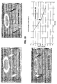
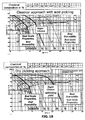
- the structure of the scale and the growth kinetics depend both on the steel and on the atmosphere. Compared to pure iron, steel oxidation is affected by the behaviour of the alloying elements. The phenomena are complex but can be summarized by stating that the scale formed on steel consist of iron oxides and contains FeO, Fe 3 O 4 , and Fe 2 O 3 and Fe(OH) 3 or FeOOH on steel with rusting. In pure air or oxygen, the scale formed on pure iron consists of several layers. Under 570°C, the graphs of Fig. 5 show that FeO is unstable and only Fe 3 O 4 and Fe 2 O 3 are present; while, at higher temperatures, an internal layer of FeO forms on the metal in addition to the two oxides.
- the heating means of the pickling device in accordance with the invention must be able to provide the energy quickly, keeping oxidation to a minimum or eliminating it completely, and without modifying the specific surface of the material, which would slow-down oxides reduction speed.
- the pickling device comprises, in a first advantageous embodiment, a microwave heating system.
- Microwave heating occurs locally and rapidly. Heat concentrated on external layers produces mainly thermal traction stresses in the oxides layers, producing fissures in the oxides layers before each pickling, be it mechanical, chemical or without acid. Microwaves remain active in the reactor of the process according to the invention only when there remains oxide since the iron and iron sponge substrates reflect microwave energy. The strong link between microwaves and water molecules produced during iron oxyde reduction with hydrogen increases heating and reaction kynetics.
- Another preferred version of the invention which is an alternative to the above described version, features a heating device of the metal product to be descaled that uses intensified radiation.
- This device is based on the optimization of the view factor.
- This view factor is defined as the portion of the total radiant energy emitted by a surface A 1 that is captured by a surface A 2 .
- the factor F 1-2 is the portion of energy that reaches A 2 from A 1 .
- This inventive configuration of the heating device considerably increases the efficiency of the process implemented with the device of the invention since the surfaces emit and absorb in a diffused manner.
- the overall effect is incremented by the fact that the atmosphere between the two surfaces does not contribute, meaning that it does not absorb or disperse, to the radiation of the surface and does not emit any radiation, in the case of an inert or reducing atmosphere or of the products of reaction.
- the gases that do not have a polarity are transparent to the radiation and the only type with a polarity, water vapor, is always kept under a certain level, for example with the use of dehumidifying means.
- the process of the invention produces excellent results even with the use of direct-fired burners, both with a naked and partially screened flame, regardless of the burnt gas mixture.
- This invention makes it possible to use pre-mixed or not burners; sub-stoichiometric, stoichiometric, or over-stoichiometric burners; and air or oxygen burners.
- Different combinations of convection heating mechanisms can be used for the combustion products together with radiating systems. Any type of radiative heating system, both with electric or gas tubes, is suitable for use in this invention.
- the geometry of the flame, the content of oxygen and other products in the gaseous state, the area temperature, and the relative velocities between the surface to be treated and the atmosphere in the heating area can be combined in different ways to obtain different heating speeds or different consumptions in order to obtain always homogenous heating that maintains or increases the reactivity of the surface without reducing the specific surface or increasing the thickness of the scale. All these heating treatments are realized without the use of any protective oils on the metal surface to be treated .
- the induction heating method is different from the ones described above since it inverts the sense of the thermal gradient.
- An induction heating system can be perfectly integrated in the process of this invention both individually and in combination with any of the previously listed heating methods.
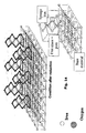
- this invention features an innovative management of induction heating, the so-called modulated frequency induction heating.
- Fig. 11 and Fig. 12 show the principle of this process. The heating frequencies are changed as the heating/reducing process progresses in order to generate the thermal flows in the conductive areas closest to the reaction front, limiting electricity consumption and improving the kinetics of the line making it more compact and efficient.
- the second phase of the pickling process which can follow or occur simultaneously with the above described heating phase, advantageously supplies the reducing gas already heated from the start of the process to improve the surface reactivity of the metal product in addition to improving the heating of the product. This should be carried out in particular when hydrogen is used as reducing gas.
- the reducing gas can be heated between 300 and 1100 °C making it flow before injecting it into the reaction area through ducts covered with preheated refractory material, or by convection by means of a heated shield on the surface opposite to the one in contact with the gas; either solution does not affect the reduction obtained through the process.
- Hydrogen is particularly suitable for heating the metal since it is 15 times lighter than air, is highly convective, has a high thermal conductivity level.
- An advantage of preheating with a hot reducing gas is that the reduction starts as soon as the first point of the metal surface becomes active.
- the formation of the first nucleus of the scale reduced by the gas leads to the formation of a spongy sublayer.
- the sublayer that has reacted with the gas maintains a much larger specific surface in addition to a deeper and wider porosity. This porous structure exists throughout the heating process.
- the role of the aforementioned initial nucleus is similar to the one carried out by the cracks in conventional pickling with acid: make the reagent penetrate deeply into the structure of the scale to perform a deep and fast reduction process.
- the boundary layer and the pressure of the reducing gas on the strip are also controlled.
- the invention includes the production of pressure oscillations, which follow a regular pattern, on the surface of the metal product.
- the aim of these disturbancies is both to generate reducing gas feeding zones followed by reaction products evacuation zone and to make the boundary layer unsteady, particularly its laminar sub-layer. In case this layer would be saturated with reaction products, e.g. water vapor, it would inhibit , reaction prosecution.
- oscillations are calculated to create a distribution in space that optimizes both the flow of the reducing gas to the surface to be reduced and the immediate removal of the water vapor produced by the reaction.
- This control is carried out by means of a particularly advantageous configuration of the reactor or of the area of the pickling line Where the reaction takes place.
- This configuration of the reactor facilitates the production of a current along the surface of the metal product with a «piston effect» while the configuration of the channel of the reactor creates an oscillating pressure field fixed in space.
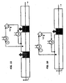
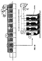
- the channel In a first version of the channel of the reactor, the channel consists of a series of tubes, with a specific pitch separating them as shown In Fig. 17 .
- the channel of the flow is realized to ensure maximum efficiency for many different types of scale and the fastest possible processing rate; since the optimal frequency does not vary much with different types of scale and the frequency of oscillation of the pressure, seen from the product that advances, it can be adjusted slightly with small changes to the process speed.
- the gas velocity at the surface of the product must be greater than 5m/sec, as an average in the boundary sub-layer, in every point of the surface of the product to be treated.
- FIG. 16 and in Fig. 18 includes the subdivision of the length of the reaction into a number of segments, each equipped with tubes, in order to ensure the alternation of the pressure effect (overpressurized area), which ensures the penetration of the reducing gas, with the suction effect (depressurized area), which ensures the elimination of the reaction products.
- the invention includes a series of heating tubes, each of which is located after a respective Venturi tube 16, 17, arranged with the axis perpendicular to the surface of the metal product. In each tube, the reducing gas is heated before heating the surface of the product.
- Fig. 18 shows schematically only the part above the metal product to be treated; however, it is understood that the part underneath the metal product, in this case a strip, is symmetric and has been omitted in the figure only to facilitate understanding.
- the above described means which enable the control of the fluid dynamics of the boundary layer, are placed at a distance from the surface to be treated comprised between 2 mm and 500 mm.
- Fig. 17 shows how the direction of the flows of the reducing gas, including any recycled gas, regardless of whether they flow in the same or opposite direction, the pressure 13, and the changing static pressure of the velocity fields 14 are independent from each other.
- a further advantageous embodiment shown in Fig. 23 , consists of a plurality of perforated diffusers collectors A 1 generating organised jets C 1 on the strip surface alternated to a plurality of perforated evacuation collectors B 1 providing evacuation of reaction products.
- the outflow jets generate an interruption of the boundary layer D 1 and a complete mixing of the reaction products which are on the surface with the reducing gas flow.
- the evacuation collectors B 1 provide the evacuation from the reactor of the gas contaminated by the reaction products.
- a simplified embodiment, having a similar efficiency, is obtained by taking off the evacuation collectors B 1 placed between two blowing collectors A 1 and producing a gas evacuation effect by means of a collision of the streams generated on the strip surface by two consecutive jet rows. These two tangential flows directed in opposite directions generate, by colliding, a zone D 1 of high turbulence and underpressure from which the gas is moved away orthogonally to the strip surface.
- An advantage of the solution of the invention is that since every lamination scale has its own morphology and roughness of the surface of the product, the reaction velocity and the removal of water vapour can be adequately increased by selecting precise types of waves (pressure oscillations and amplitude of pressure and frequency differences over time).
- the special configuration of the reactor that creates the surface pressure oscillations has the advantage of removing water vapor from the surface of the metal product much more efficiently than in conventional reactors. Pressure oscillations, in fact, destabilize the layer of water vapor and cause the water to be suctioned from the surface.
- the content of water in the oxide that forms the scale must be low enough to allow acceptable reduction speeds; hence, this content must be kept below 5% in volume at all times and in all points of the reaction segment.
- This segment is comprised between the point in which the product has a temperature of 100°C and the point where the product reaches its maximum temperature. This tight control on the levels of water vapor is assured by the presence of the aforementioned recycling equipment fitted with said dehumidification system.
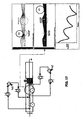
- a dehumidification system in accordance with the invention which can be used in combination with either described form of realization of the reactor, is shown in greater detail in Fig. 15 .
- This can be of the cryogenic type, with an absorption or mechanical mechanism depending on the dimensions of the prickling plant. It includes a heat exchanger 4 for the primary elimination of the water after the dehumidification system.
- a second unit of heat exchangers brings the gas to operating temperatures.
- the first part of the last heat exchanger is the same as the one described above 4; in addition, it includes an optional unit for remitting the gas in the channel of the reactor at the appropriate convective potential.
- This dehumidification system is balanced in accordance with the diagram in Fig. 11 .
- the gas flow rates vary from 1000 Nm 3 /h up to 50000 Nm 3 /h, and the dew point of the recycled gas ranges from -50°C to 0°C.
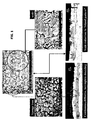
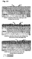
- Figures 13 and 14 show the morphological change at the microscopic level that takes place on the surface of the product that is treated using the process of the invention.
- An advantage derived directly from the pickling process of the invention is that the changes to the surface of the product that occur at a very early stage of the process, due to the formation of the macroscopically porous structure, increase the reactivity of the material regardless of the used heating system in the initial phase of the process, whether the system consists of burners, radiant tubes, electric, induction, electromagnetic, etc.
- the essential condition to guarantee high kinetics in the reaction is the proper removal of the water from the layer involved in the reaction. The removal of water also depends on the original structure of the scale (essentially unchangeable) and sponge iron, which forms in the early stages of the process, and on the partial water pressure on the boundary layer, which is controlled by the thermal fluid dynamic devices described above.
- a very interesting aspect of the dry descaling process carried out in the device of the invention is that it allows better adjustment between the cooling program of the product in the train of rolls and the nature of the scale, especially for drawing that takes place later on.
- the cooling choice is a compromise between optimal scale results and the levels of production of the rolling mill.
- reactivity is not very affected by the nature of the present oxide; rather, it is more affected by the geometry of the surface.
- the cooling program of the product can be chosen as a function of the desired productivity, but staying close to the optimal microstructure and scale thickness, since the longer the product is kept at a higher temperature, the thicker the scale and the lower the productivity.
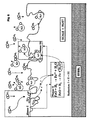
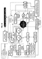
- Fig. 21 shows a schematic view of the pickling process of the invention, with the relation between the process variables.
- the cooling of the product after reduction occurs by means of forced convection using hydrogen as cooling gas.
- gases of the inert type nitrogen, argon
- the use of hydrogen reduces the length of the plant and brings the temperatures of the reduced material below the reoxidation temperature limit.
- the layer of sponge iron can be easily removed totally and homogeneously by mechanical means (brushing, shot peeing, CO 2 , etc.).
- the surface structure of the strip after the reduction treatment and brushing is shown in Fig. 22 .
- the dry descaling operation consists in removing the oxygen from the scale of iron and in leaving a layer of "sponge iron" that is removed from the surface by a mechanical action (brushing, shot peeing, CO 2 , etc.). Brushing, in this case, is not a true pickling operation because only iron is removed, since the oxide has already been removed.
- Fig. 6 shows the process of the invention in graphical form; the three main sequential phases are shown, specifically: the injection of the gas in close contact with the surface to be reduced, the reducing reaction, and the removal of the reaction products (water) to free other sections of the surface so that reduction can take place.
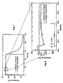
- Figures 7 and 8 show the results of the reduction tests in an initial vacuum with heating of the sample.
- the reaction is denoted by a drop in the temperature (endothermic reaction).
- This test shows that the reduction reaction is practically instantaneous; thus, it is necessary to optimize the reagent supply phase and the removal of the water phase by controlling the boundary layer and creating alternating pressure and suction areas .
- Fig. 9 shows the perfectly homogeneous progress and the completed reduction reaction shown in Figures 7 and 8 .
- the process is particularly suited to pickling metal products coming directly from the rolling mill or products that come wound around coils, unwound from the coil, and heated. In fact, the process does not change any of the properties of the rolled material. No phase transformation occurs since the material does not exceed any transformation line.
- the process is optimized to achieve reactivity as of the lowest temperature and as soon as possible; other goals include performing the process in a contained length plant and reducing the duration of the process. Besides taking place without the use of acids, the process also does not use condensing reagents, which would slow down the speed of reaction.
- the process is carried out in a single pass of the product through the pickling plant, at a speed that can vary between 10 to 100 m/min; the product must stay in the reaction area for minimum 20 sec and maximum 90 sec.
- a preferred version of the acid-free pickling plant sizes the device so that it can treat from a minimum of 50,000t/year to a maximum of 1,000,000t/year of metal products.
Landscapes
- Chemical & Material Sciences (AREA)
- Chemical Kinetics & Catalysis (AREA)
- General Chemical & Material Sciences (AREA)
- Engineering & Computer Science (AREA)
- Materials Engineering (AREA)
- Mechanical Engineering (AREA)
- Metallurgy (AREA)
- Organic Chemistry (AREA)
- Cleaning And De-Greasing Of Metallic Materials By Chemical Methods (AREA)
- Drying Of Solid Materials (AREA)
- Detergent Compositions (AREA)
- Physical Or Chemical Processes And Apparatus (AREA)
Claims (33)
- Trocken-Entzunderungsvorrichtung für das Entfernen von Zunder von einer Oberfläche eines Metallprodukts, umfassend:mindestens einen Heizbereich zum Aufheizen des Metallprodukts,mindestens einen Desoxidationsbereich zum Durchführen einer Reaktion zwischen einem Metalloxid-Desoxidationsgas und mindestens dem Zunder,mindestens einen Bereich zum Abkühlen des Metallprodukts,eine erste Heizeinrichtung zum Erwärmen des Metallprodukts,eine zweite Heizeinrichtung zum Erwärmen des Desoxidationsgases,eine Einrichtung zum Entfernen von Reaktionsprodukten von dem Desoxidationsgas nach der Reaktion,eine Einrichtung zum Entfernen von Reaktionsprodukten, die auf der Oberfläche des Metallprodukts nach der Behandlung verbleiben, undeine Einrichtung zum Kühlen des Metallprodukts; eine erste Steuereinrichtung (16, 17 B1, C1) zur fluiddynamischen Steuerung der durch den Strom des Desoxidationsgases über die Oberfläche des Metallprodukts erzeugten Grenzschicht, wobei die erste Steuereinrichtung angepasst ist zum Erzeugen von Regeldruckschwingungen, die Überdruck- und Druckverminderungsbereiche umfassen, welche aufeinanderfolgend entlang der gesamten Oberfläche des Metallprodukts wiederholt werden,wobei die Überdruckbereiche einer Desoxidationsgasblasestufe in Richtung der Oberfläche des Metallprodukts zugeordnet sind,
eine zweite Steuereinrichtung zum Steuern der chemischen Zusammensetzung des Desoxidationsgases während der Blasestufe,
eine dritte Steuereinrichtung zum Steuern der Desoxidationsgas-Temperatur, wobei die Trockenabbeizvorrichtung gekennzeichnet ist durch die Tatsache, dass sie umfasst:dass die Druckverringerungsbereiche einer Evakuierungsphase des Desoxidationsgases stromabwärts von der Blasestufe zugeordnet sind, undeine Einrichtung, die angepasst ist zum Reinigen und Wiederaufbereiten von Desoxidationsgas nach der Desoxidationsoperation des Zunders. - Vorrichtung nach Anspruch 1, wobei der Druck oberhalb on +10 Pa in den Überdruckbereichen ist und wobei der Druck oberhalb von -2 Pa im Absolutwert in den Druckverringerungsbereichen liegt.
- Vorrichtung nach Anspruch 1, wobei die erste Steuereinrichtung mehrere Venturirohre (16, 17) bei einem reziproken Abstand, der zwischen 10 mm und 1500 mm umfasst, angeordnet hat mit ihren Achsen entlang der Förderrichtung dies Metallprodukts positioniert.
- Vorrichtung nach Anspruch 1, wobei die erste Steuereinrichtung mehrere Rohrpaare umfasst, wobei jedes Rohrpaar aus einem Heizrohr und einem stromabwärts von dem Heizrohr angeordneten Venturirohr besteht, die Rohre des Rohrpaares senkrecht zu der Oberfläche des Metallprodukts verlaufende Achsen haben und bei reziproker Distanz, die zwischen 10 mm und 1500 mm umfasst, angeordnet sind.
- Vorrichtung nach Anspruch 1, wobei die erste Steuereinrichtung in einem Abstand von der Oberfläche des Metallprodukts angeordnet ist, der zwischen 2 mm und 500 mm umfasst.
- Vorrichtung nach Anspruch 1, wobei die erste Heizeinrichtung eine Mikrowellenvorrichtung umfasst.
- Vorrichtung nach Anspruch 1, wobei die erste Heizeinrichtung einen Heizkonvektionsstrom des Desoxidationsgases umfasst, das zuvor auf eine Temperatur erwärmt worden ist, die zwischen 300 °C und 1100 °C umfasst.
- Vorrichtung nach Anspruch 1, wobei die erste Heizeinrichtung Induktionsheizelemente mit oder ohne Frequenzmodulation umfasst.
- Vorrichtung nach Anspruch 1, wobei die erste Heizeinrichtung Luft- oder Sauerstoffbrenner mit einer nackten oder abgeschirmten Flamme umfasst.
- Vorrichtung nach Anspruch 1 wobei die erste Heizeinrichtung Gas- oder Elektrostrahlungsrohre umfasst.
- Vorrichtung nach Anspruch 1, wobei die erste Heizeinrichtung verstärkte Strahlungsheizelemente umfasst.
- Vorrichtung nach Anspruch 1, wobei die erste Heizeinrichtung eine Mikrowellenvorrichtung und/oder eine Konvektionsstromvorrichtung zum Erwärmen des Desoxidationsgases umfasst, das zuvor auf eine Temperatur erwärmt worden ist, die zwischen 300 °C und 1100 °C umfasst und/oder Induktionsheizelemente und/oder Luft- oder Sauerstoffbrenner mit einer nackten oder abgeschirmten Flamme und/oder Gas- oder Elektrostrahlungsrohre und/oder verstärkte Strahlungsheizelemente.
- Vorrichtung nach Anspruch 1, wobei die zweite Heizeinrichtung mindestens eine Rohrführung aus hitzebeständigem Material umfasst, durch die das Desoxidationsgas fließt oder mindestens eine elektrisch beheizte oder durch eine mit dem Desoxidationsgas beleckte Flamme beheizte Metallwand.
- Vorrichtung nach Anspruch 1, wobei die Einrichtung zum Kühlen des Metallprodukts ein durch Inert- oder Desoxidationsgas verstärktes Konvektionssystem umfasst.
- Vorrichtung nach Anspruch 1, wobei die Einrichtung zum Entfernen der Reaktionsprodukte von dem Desoxidationsgas nach der Reaktionsstufe mindestens eine Tieftemperatur- und/oder Absorptions- und/oder mechanische Anlage umfasst.
- Vorrichtung nach Anspruch 1, wobei die Einrichtungen zum Entfernen der Reaktionsprodukte, die auf der Oberfläche des behandelten Metallprodukts verbleiben, hinter dem Kühlbereich angeordnet sind und eine mechanische Bürsteinrichtung umfassen.
- Vorrichtung nach einem oder mehreren der vorangehenden Ansprüche, wobei die Heiz-, Desoxidations- und Kühlbereiche in einer gemeinsamen Kammer angeordnet sind, die die ersten und zweiten Heizeinrichtungen, die erste Steuereinrichtung und die Einrichtung zum Kühlen des Metallprodukts einschließt.
- Trocken-Entzunderungsprozess zum Entfernen des Zunders auf der Oberfläche eines Metallprodukts, welcher Prozess mit der Trockenbeizvorrichtung nach einem der vorhergehenden Ansprüche ausgeführt wird, umfassend
mindestens einen Heizbereich zum Heizen des Metallprodukts,
mindestens einen Desoxidationsbereich zum Vornehmen einer Reaktion zwischen einem Metalloxid des Desoxidationsgas und mindestens dem Zunder,
mindestens einen Bereich zum Kühlen des Metallprodukts,
eine erste Heizvorrichtung zum Heizen des Metallprodukts,
eine zweite Heizvorrichtung zum Heizen des Desoxidationsgases,
eine Einrichtung zum Entfernen von Reaktionsprodukten von dem Desoxidationsgas nach der Reaktion,
eine Einrichtung zum Entfernen von Reaktionsprodukten, die auf der Oberfläche des Metallprodukts nach der Behandlung verbleiben, und
eine Einrichtung zum Kühlen des Metallprodukts,
wobei der Prozess die folgenden Schritte umfasst:a) Bereitstellen eines Metalloxid-Desoxidationsgases,b) Erwärmen des Metallprodukts auf eine erste Temperatur, die höher ist als die Umgebungstemperatur, ohne Desoxidieren und ohne Oxidieren der spezifischen Oberfläche des zu behandelnden Materials,c) Erwärmen des Desoxidationsgases auf eine zweite Temperatur, die höher ist als die Umgebungstemperatur,d) Einfügen des Metallprodukts in den Reaktionsbereich,e) Vornehmen der Reaktion zwischen dem Metalloxid-Desoxidationsgas und mindestens dem Zunder,f) Kühlen des Metallprodukts,g) Entfernen der Reaktionsprodukte von dem Desoxidationsgas nach der Reaktion mit dem Zunder,h) Entfernen der Reaktionsprodukte von der Oberfläche des behandelten Metallprodukts,i) Steuern der Fluid-Dynamiken von der Randschicht des Desoxidationsgasstroms über die Oberfläche des Metallprodukts mit Hilfe der ersten Steuereinrichtung (16, 17, 19, A1, B1, C1), wobei eine organisierte Gasverteilung und homogene Gaskonzentrationen in dem Umfang des auf der Oberfläche gefundenen Zunders vorgesehen sind und in zum Entfernen der Reaktionsprodukte von dem Desoxidationsgas ausreichender Weise,j) Bereitstellen einer Blasstufe des erwärmten Desoxidationsgases auf die Oberfläche des Metallprodukts bei einer vorbestimmten Durchflussrate, die in dem Bereich von 4 bis 100 Nm3/(min-kgscale) umfasst wird,k) Bereitstellen einer in dem Bereich von 20 bis 90 s umfassten Reaktionszeit zum Entfernen von Wasserstoff von dem Zunder,l) Bereitstellen eines Evakuierungsstroms des Desoxidationsgases mit Hilfe der Randschichtfluiddynamiksteuereinrichtung, nachdem es in Übereinstimmung mit der Stufe k) reagiert hat, nach dem Zulieferstrom, wodurch der Evakuierungsstrom einem entsprechenden Druckminderungsbereich auf der Oberfläche des Metallprodukts zugeordnet wird,m) Durchführen der Stufen j) und l) zyklisch in regelmäßiger Aufeinanderfolge entlang der gesamten Oberfläche des Metallprodukts,n) Entfernen der Reaktionsprodukte von dem Desoxidationsgas nach der Reaktion mit dem Zunder. - Prozess nach Anspruch 18, wobei die Reaktionsprodukte, die auf der Oberfläche des behandelten Metallproduktes verbleiben, entfernt werden.
- Prozess nach Anspruch 18, wobei der Druck in den Überdruckbereichen oberhalb von +10 Pa liegt.
- Prozess nach Anspruch 18, wobei in dem Druckverringerungsbereich der Druck oberhalb von -2 Pa im Absolutwert liegt.
- Prozess nach Anspruch 18, wobei das Desoxidationsgas in Kombination mit anderen Inert- und/oder Desoxidationsgasen verwendet wird.
- Prozess nach Anspruch 18, wobei das Desoxidationsgas Sauerstoff ist und die Inertgase vorzugsweise Stickstoff und/oder Helium und/oder Argon sind.
- Prozess nach Anspruch 18, wobei in Übereinstimmung mit dem Schritt n) eine Wasserdampfkonzentration an allen Punkten unterhalb von 5% in Volumen gehalten wird.
- Prozess nach Anspruch 18, wobei das Desoxidationsgas auf eine Temperatur erwärmt wird, die zwischen 300 °C und 1100 °C umfasst.
- Prozess nach Anspruch 18, wobei das Erwärmen des Metallprodukts durch Mikrowellenstrahlen und/oder einen Desoxidationsgas-Heizkonvektionsstrom und/oder durch Induktion und/oder durch Flamme und/oder durch Radiation ausgeführt wird.
- Prozess nach Anspruch 18, wobei das Heizen des Desoxidationsgases mit Hilfe von Kontakt mit erwärmten feuerfesten Materialien und/oder erwärmten Metallwänden erzielt wird.
- Prozess nach Anspruch 18, wobei die Grenzschichtfluid-Dynamiksteuerung mit Hilfe mehrerer Venturi-Rohre vorgenommen wird, die koaxial bei einer reziproken Distanz, die zwischen 10 mm und 1500 mm umfasst, angeordnet sind, und die ihre Achsen entlang der Förderrichtung des Metallprodukts angeordnet haben.
- Prozess nach Anspruch 18, wobei die Grenzschichtfluid-Dynamiksteuerung mit Hilfe einer Reihe von Rohrpaaren vorgenommen wird, wobei jedes Rohrpaar aus einem Heizrohr und einem stromabwärts von dem Heizrohr angeordneten Venturi-Rohr gebildet wird, wobei die Rohre der Rohrpaare senkrecht zur Oberfläche des Metallprodukts angeordnete Achsen haben, und wobei die Rohre in einer reziproken Distanz angeordnet sind, die zwischen 10 mm und 1500 mm umfasst.
- Prozess nach Anspruch 18, wobei das Entfernen der Reaktionsprodukte von dem Desoxidationsgas nach der Reaktion mit Hilfe einer Tieftemperatur- und/oder Absorptions- und/oder mechanischen Wirkung durchgeführt wird.
- Prozess nach Anspruch 18, wobei das Kühlen des Metallprodukts mit Hilfe von Inertgaszwangskonvektion vorgenommen wird.
- Prozess nach Anspruch 18 und 29, einen Schritt des Wiedereinspeisens des Desoxidationsgases in den Zyklus umfassend, nachdem die Reaktionsprodukte entfernt worden sind.
- Prozess nach Anspruch 19, wobei die auf der Oberfläche des Metallprodukts gefundenen Reaktionsprodukte durch Bürsten entfernt werden.
Applications Claiming Priority (3)
| Application Number | Priority Date | Filing Date | Title |
|---|---|---|---|
| IT002424A ITMI20022424A1 (it) | 2002-11-15 | 2002-11-15 | Dispositivo e processo di rimozione a secco della scaglia |
| ITMI20022424 | 2002-11-15 | ||
| PCT/EP2003/012781 WO2004046423A1 (en) | 2002-11-15 | 2003-11-14 | An apparatus and process for the dry removal of the scale found on the surface of metal products |
Publications (2)
| Publication Number | Publication Date |
|---|---|
| EP1579036A1 EP1579036A1 (de) | 2005-09-28 |
| EP1579036B1 true EP1579036B1 (de) | 2008-10-29 |
Family
ID=32321424
Family Applications (1)
| Application Number | Title | Priority Date | Filing Date |
|---|---|---|---|
| EP03767550A Expired - Lifetime EP1579036B1 (de) | 2002-11-15 | 2003-11-14 | Vorrichtung und verfahren zum trockenen entfernen von zunder auf der oberfläche von metallprodukten |
Country Status (9)
| Country | Link |
|---|---|
| US (2) | US7520946B2 (de) |
| EP (1) | EP1579036B1 (de) |
| CN (1) | CN100491596C (de) |
| AT (1) | ATE412791T1 (de) |
| AU (1) | AU2003292025A1 (de) |
| DE (1) | DE60324464D1 (de) |
| ES (1) | ES2316827T3 (de) |
| IT (1) | ITMI20022424A1 (de) |
| WO (1) | WO2004046423A1 (de) |
Families Citing this family (6)
| Publication number | Priority date | Publication date | Assignee | Title |
|---|---|---|---|---|
| DE102004060086A1 (de) * | 2004-12-14 | 2006-06-22 | Sms Demag Ag | Verfahren und Vorrichtung zum Bandabblasen im Auslauf von Walzwerken zur Erzeugung von tropfenfreiem und sauberem Walzband |
| CN101758044B (zh) * | 2008-11-05 | 2015-10-07 | 赵钦基 | 电热清洁法及器件 |
| CN102698996A (zh) * | 2012-05-30 | 2012-10-03 | 圣睿太阳能科技(镇江)有限公司 | 非晶硅薄膜太阳能电池pecvd基片装载箱清洁系统及清洁方法 |
| JP6080011B2 (ja) * | 2013-05-31 | 2017-02-15 | 澁谷工業株式会社 | 鉄製加工物の錆除去方法およびその装置 |
| CN107502907B (zh) * | 2017-07-29 | 2018-12-21 | 阜南县永兴工艺品有限公司 | 一种铁质工艺品除锈的方法 |
| CN113000613A (zh) * | 2021-02-09 | 2021-06-22 | 鞍钢股份有限公司 | 一种避免热处理后钢管外表面产生麻面缺欠的控制方法 |
Family Cites Families (8)
| Publication number | Priority date | Publication date | Assignee | Title |
|---|---|---|---|---|
| US4576837A (en) * | 1985-03-19 | 1986-03-18 | Tarancon Corporation | Method of treating surfaces |
| CN2036081U (zh) * | 1988-08-11 | 1989-04-19 | 四川省地质矿产局一○二厂 | 可移式喷浆除锈机 |
| CN2287529Y (zh) * | 1994-07-29 | 1998-08-12 | 徐兆夫 | 无酸拉丝除锈机 |
| DE19519544C2 (de) | 1995-05-27 | 1999-08-19 | Sundwig Gmbh | Vorrichtung zum Entfernen von Flüssigkeit von der Oberfläche eines Bandes |
| CN2248601Y (zh) * | 1996-03-28 | 1997-03-05 | 顾乃健 | 一种除锈机 |
| JP2000514002A (ja) * | 1996-06-24 | 2000-10-24 | ズンドビク ゲゼルシャフト ミット ベシュレンクテル ハフツング | シート表面から液体を除去するための液体除去装置 |
| US6217666B1 (en) * | 1998-08-31 | 2001-04-17 | Danieli Technology, Inc. | Countercurrent reduction of oxides on moving metal |
| DE19900427A1 (de) * | 1999-01-08 | 2000-07-13 | Sms Demag Ag | Verfahren und Vorrichtung zum Entzundern einer Oszillationsmarken aufweisenden Oberfläche eines Gußstranges aus einer Stranggießanlage |
-
2002
- 2002-11-15 IT IT002424A patent/ITMI20022424A1/it unknown
-
2003
- 2003-11-14 WO PCT/EP2003/012781 patent/WO2004046423A1/en not_active Ceased
- 2003-11-14 US US10/535,127 patent/US7520946B2/en not_active Expired - Fee Related
- 2003-11-14 ES ES03767550T patent/ES2316827T3/es not_active Expired - Lifetime
- 2003-11-14 DE DE60324464T patent/DE60324464D1/de not_active Expired - Lifetime
- 2003-11-14 EP EP03767550A patent/EP1579036B1/de not_active Expired - Lifetime
- 2003-11-14 US US12/310,838 patent/US8109283B2/en not_active Expired - Fee Related
- 2003-11-14 CN CNB2003801033252A patent/CN100491596C/zh not_active Expired - Fee Related
- 2003-11-14 AU AU2003292025A patent/AU2003292025A1/en not_active Abandoned
- 2003-11-14 AT AT03767550T patent/ATE412791T1/de active
Also Published As
| Publication number | Publication date |
|---|---|
| WO2004046423A1 (en) | 2004-06-03 |
| ITMI20022424A1 (it) | 2004-05-16 |
| US7520946B2 (en) | 2009-04-21 |
| CN1711371A (zh) | 2005-12-21 |
| US8109283B2 (en) | 2012-02-07 |
| US20060163781A1 (en) | 2006-07-27 |
| EP1579036A1 (de) | 2005-09-28 |
| DE60324464D1 (de) | 2008-12-11 |
| ES2316827T3 (es) | 2009-04-16 |
| ATE412791T1 (de) | 2008-11-15 |
| CN100491596C (zh) | 2009-05-27 |
| AU2003292025A1 (en) | 2004-06-15 |
| US20100242990A1 (en) | 2010-09-30 |
Similar Documents
| Publication | Publication Date | Title |
|---|---|---|
| US8057604B2 (en) | Method and device for descaling metal strip | |
| KR20090089317A (ko) | 소둔 및 산세 방법 | |
| EP1579036B1 (de) | Vorrichtung und verfahren zum trockenen entfernen von zunder auf der oberfläche von metallprodukten | |
| KR20050084976A (ko) | 금속 빌렛의 스케일 제거 및/또는 세정 방법 및 장치 | |
| EP3029164B1 (de) | Verfahren zur Behandlung eines Edelstahlbandes, insbesondere zur Abbeizungsbehandlung | |
| AU4091799A (en) | Method for continuous removal of oxides from metal | |
| CN102292172A (zh) | 用于对由不锈钢制成的带材进行退火和除鳞的方法和设备 | |
| RU2463152C2 (ru) | Способ абразивно-струйной очистки поверхностей металлов | |
| JP2000033417A (ja) | 鉄系線材の脱スケール方法及び装置 | |
| JP2949642B2 (ja) | ステンレス鋼の脱スケール処理法と装置 | |
| US5783000A (en) | Method for heat treatment of steel, and products of steel | |
| EP2687611A1 (de) | Verfahren und Vorrichtung zur Steuerung der Oberflächenporosität von Metallmaterialien | |
| US3956010A (en) | Dry pickling method | |
| CN107583964A (zh) | 易酸洗焊丝钢高速线材的生产方法 | |
| JP2705382B2 (ja) | 軸受用鋼管の酸洗前処理方法 | |
| JPS6033188B2 (ja) | 金属熱処理設備 | |
| JP2981384B2 (ja) | 鋼帯の浸炭方法 | |
| US20040050465A1 (en) | Quenching method and apparatus | |
| US20070095434A1 (en) | Long products, method of thermo-chemical treatment and apparatus | |
| JPS63759Y2 (de) | ||
| JPH0681097A (ja) | 酸化スケ−ル付着鉄鋼加工品の溶融亜鉛めっき方法 | |
| JPS59190328A (ja) | 金属管の冷却方法および装置 | |
| ZA200209827B (en) | Method and device for pickling hot-roled special steel strips. | |
| CN209039538U (zh) | 一种不锈钢丝连续退火装置 | |
| RU2023030C1 (ru) | Способ обработки проволоки и устройство для его осуществления |
Legal Events
| Date | Code | Title | Description |
|---|---|---|---|
| PUAI | Public reference made under article 153(3) epc to a published international application that has entered the european phase |
Free format text: ORIGINAL CODE: 0009012 |
|
| 17P | Request for examination filed |
Effective date: 20050614 |
|
| AK | Designated contracting states |
Kind code of ref document: A1 Designated state(s): AT BE BG CH CY CZ DE DK EE ES FI FR GB GR HU IE IT LI LU MC NL PT RO SE SI SK TR |
|
| AX | Request for extension of the european patent |
Extension state: AL LT LV MK |
|
| DAX | Request for extension of the european patent (deleted) | ||
| GRAP | Despatch of communication of intention to grant a patent |
Free format text: ORIGINAL CODE: EPIDOSNIGR1 |
|
| RIC1 | Information provided on ipc code assigned before grant |
Ipc: C23G 5/00 20060101AFI20080407BHEP Ipc: B08B 7/00 20060101ALI20080407BHEP |
|
| GRAS | Grant fee paid |
Free format text: ORIGINAL CODE: EPIDOSNIGR3 |
|
| GRAA | (expected) grant |
Free format text: ORIGINAL CODE: 0009210 |
|
| AK | Designated contracting states |
Kind code of ref document: B1 Designated state(s): AT BE BG CH CY CZ DE DK EE ES FI FR GB GR HU IE IT LI LU MC NL PT RO SE SI SK TR |
|
| REG | Reference to a national code |
Ref country code: GB Ref legal event code: FG4D |
|
| REG | Reference to a national code |
Ref country code: CH Ref legal event code: EP |
|
| REG | Reference to a national code |
Ref country code: IE Ref legal event code: FG4D |
|
| REF | Corresponds to: |
Ref document number: 60324464 Country of ref document: DE Date of ref document: 20081211 Kind code of ref document: P |
|
| RAP2 | Party data changed (patent owner data changed or rights of a patent transferred) |
Owner name: DANIELI & C. OFFICINE MECCANICHE S.P.A. |
|
| PGFP | Annual fee paid to national office [announced via postgrant information from national office to epo] |
Ref country code: ES Payment date: 20081229 Year of fee payment: 6 |
|
| NLV1 | Nl: lapsed or annulled due to failure to fulfill the requirements of art. 29p and 29m of the patents act | ||
| REG | Reference to a national code |
Ref country code: ES Ref legal event code: FG2A Ref document number: 2316827 Country of ref document: ES Kind code of ref document: T3 |
|
| PG25 | Lapsed in a contracting state [announced via postgrant information from national office to epo] |
Ref country code: BG Free format text: LAPSE BECAUSE OF FAILURE TO SUBMIT A TRANSLATION OF THE DESCRIPTION OR TO PAY THE FEE WITHIN THE PRESCRIBED TIME-LIMIT Effective date: 20090129 |
|
| PG25 | Lapsed in a contracting state [announced via postgrant information from national office to epo] |
Ref country code: SI Free format text: LAPSE BECAUSE OF FAILURE TO SUBMIT A TRANSLATION OF THE DESCRIPTION OR TO PAY THE FEE WITHIN THE PRESCRIBED TIME-LIMIT Effective date: 20081029 Ref country code: FI Free format text: LAPSE BECAUSE OF FAILURE TO SUBMIT A TRANSLATION OF THE DESCRIPTION OR TO PAY THE FEE WITHIN THE PRESCRIBED TIME-LIMIT Effective date: 20081029 Ref country code: PT Free format text: LAPSE BECAUSE OF FAILURE TO SUBMIT A TRANSLATION OF THE DESCRIPTION OR TO PAY THE FEE WITHIN THE PRESCRIBED TIME-LIMIT Effective date: 20090330 Ref country code: NL Free format text: LAPSE BECAUSE OF FAILURE TO SUBMIT A TRANSLATION OF THE DESCRIPTION OR TO PAY THE FEE WITHIN THE PRESCRIBED TIME-LIMIT Effective date: 20081029 |
|
| PG25 | Lapsed in a contracting state [announced via postgrant information from national office to epo] |
Ref country code: MC Free format text: LAPSE BECAUSE OF NON-PAYMENT OF DUE FEES Effective date: 20081130 |
|
| PGFP | Annual fee paid to national office [announced via postgrant information from national office to epo] |
Ref country code: GB Payment date: 20081229 Year of fee payment: 6 |
|
| REG | Reference to a national code |
Ref country code: CH Ref legal event code: PL |
|
| PG25 | Lapsed in a contracting state [announced via postgrant information from national office to epo] |
Ref country code: RO Free format text: LAPSE BECAUSE OF FAILURE TO SUBMIT A TRANSLATION OF THE DESCRIPTION OR TO PAY THE FEE WITHIN THE PRESCRIBED TIME-LIMIT Effective date: 20081029 Ref country code: EE Free format text: LAPSE BECAUSE OF FAILURE TO SUBMIT A TRANSLATION OF THE DESCRIPTION OR TO PAY THE FEE WITHIN THE PRESCRIBED TIME-LIMIT Effective date: 20081029 Ref country code: DK Free format text: LAPSE BECAUSE OF FAILURE TO SUBMIT A TRANSLATION OF THE DESCRIPTION OR TO PAY THE FEE WITHIN THE PRESCRIBED TIME-LIMIT Effective date: 20081029 Ref country code: BE Free format text: LAPSE BECAUSE OF FAILURE TO SUBMIT A TRANSLATION OF THE DESCRIPTION OR TO PAY THE FEE WITHIN THE PRESCRIBED TIME-LIMIT Effective date: 20081029 |
|
| PG25 | Lapsed in a contracting state [announced via postgrant information from national office to epo] |
Ref country code: CZ Free format text: LAPSE BECAUSE OF FAILURE TO SUBMIT A TRANSLATION OF THE DESCRIPTION OR TO PAY THE FEE WITHIN THE PRESCRIBED TIME-LIMIT Effective date: 20081029 Ref country code: SE Free format text: LAPSE BECAUSE OF FAILURE TO SUBMIT A TRANSLATION OF THE DESCRIPTION OR TO PAY THE FEE WITHIN THE PRESCRIBED TIME-LIMIT Effective date: 20090129 |
|
| PLBE | No opposition filed within time limit |
Free format text: ORIGINAL CODE: 0009261 |
|
| STAA | Information on the status of an ep patent application or granted ep patent |
Free format text: STATUS: NO OPPOSITION FILED WITHIN TIME LIMIT |
|
| PG25 | Lapsed in a contracting state [announced via postgrant information from national office to epo] |
Ref country code: SK Free format text: LAPSE BECAUSE OF FAILURE TO SUBMIT A TRANSLATION OF THE DESCRIPTION OR TO PAY THE FEE WITHIN THE PRESCRIBED TIME-LIMIT Effective date: 20081029 |
|
| 26N | No opposition filed |
Effective date: 20090730 |
|
| PG25 | Lapsed in a contracting state [announced via postgrant information from national office to epo] |
Ref country code: IE Free format text: LAPSE BECAUSE OF NON-PAYMENT OF DUE FEES Effective date: 20081114 Ref country code: CH Free format text: LAPSE BECAUSE OF NON-PAYMENT OF DUE FEES Effective date: 20081130 Ref country code: LI Free format text: LAPSE BECAUSE OF NON-PAYMENT OF DUE FEES Effective date: 20081130 |
|
| PGFP | Annual fee paid to national office [announced via postgrant information from national office to epo] |
Ref country code: FR Payment date: 20081222 Year of fee payment: 6 |
|
| GBPC | Gb: european patent ceased through non-payment of renewal fee |
Effective date: 20091114 |
|
| PG25 | Lapsed in a contracting state [announced via postgrant information from national office to epo] |
Ref country code: LU Free format text: LAPSE BECAUSE OF NON-PAYMENT OF DUE FEES Effective date: 20081114 Ref country code: CY Free format text: LAPSE BECAUSE OF FAILURE TO SUBMIT A TRANSLATION OF THE DESCRIPTION OR TO PAY THE FEE WITHIN THE PRESCRIBED TIME-LIMIT Effective date: 20081029 Ref country code: HU Free format text: LAPSE BECAUSE OF FAILURE TO SUBMIT A TRANSLATION OF THE DESCRIPTION OR TO PAY THE FEE WITHIN THE PRESCRIBED TIME-LIMIT Effective date: 20090430 |
|
| REG | Reference to a national code |
Ref country code: FR Ref legal event code: ST Effective date: 20100730 |
|
| PG25 | Lapsed in a contracting state [announced via postgrant information from national office to epo] |
Ref country code: TR Free format text: LAPSE BECAUSE OF FAILURE TO SUBMIT A TRANSLATION OF THE DESCRIPTION OR TO PAY THE FEE WITHIN THE PRESCRIBED TIME-LIMIT Effective date: 20081029 |
|
| PG25 | Lapsed in a contracting state [announced via postgrant information from national office to epo] |
Ref country code: FR Free format text: LAPSE BECAUSE OF NON-PAYMENT OF DUE FEES Effective date: 20091130 Ref country code: GR Free format text: LAPSE BECAUSE OF FAILURE TO SUBMIT A TRANSLATION OF THE DESCRIPTION OR TO PAY THE FEE WITHIN THE PRESCRIBED TIME-LIMIT Effective date: 20090130 |
|
| PG25 | Lapsed in a contracting state [announced via postgrant information from national office to epo] |
Ref country code: GB Free format text: LAPSE BECAUSE OF NON-PAYMENT OF DUE FEES Effective date: 20091114 |
|
| REG | Reference to a national code |
Ref country code: ES Ref legal event code: FD2A Effective date: 20110308 |
|
| PG25 | Lapsed in a contracting state [announced via postgrant information from national office to epo] |
Ref country code: ES Free format text: LAPSE BECAUSE OF NON-PAYMENT OF DUE FEES Effective date: 20110307 |
|
| PG25 | Lapsed in a contracting state [announced via postgrant information from national office to epo] |
Ref country code: ES Free format text: LAPSE BECAUSE OF NON-PAYMENT OF DUE FEES Effective date: 20091115 |
|
| PGFP | Annual fee paid to national office [announced via postgrant information from national office to epo] |
Ref country code: AT Payment date: 20121024 Year of fee payment: 10 |
|
| REG | Reference to a national code |
Ref country code: AT Ref legal event code: MM01 Ref document number: 412791 Country of ref document: AT Kind code of ref document: T Effective date: 20131114 |
|
| PG25 | Lapsed in a contracting state [announced via postgrant information from national office to epo] |
Ref country code: AT Free format text: LAPSE BECAUSE OF NON-PAYMENT OF DUE FEES Effective date: 20131114 |
|
| PGFP | Annual fee paid to national office [announced via postgrant information from national office to epo] |
Ref country code: DE Payment date: 20191021 Year of fee payment: 17 |
|
| PGFP | Annual fee paid to national office [announced via postgrant information from national office to epo] |
Ref country code: IT Payment date: 20191021 Year of fee payment: 17 |
|
| REG | Reference to a national code |
Ref country code: DE Ref legal event code: R119 Ref document number: 60324464 Country of ref document: DE |
|
| PG25 | Lapsed in a contracting state [announced via postgrant information from national office to epo] |
Ref country code: IT Free format text: LAPSE BECAUSE OF NON-PAYMENT OF DUE FEES Effective date: 20201114 |
|
| PG25 | Lapsed in a contracting state [announced via postgrant information from national office to epo] |
Ref country code: DE Free format text: LAPSE BECAUSE OF NON-PAYMENT OF DUE FEES Effective date: 20210601 |