EP1578657B1 - Structure deployable - Google Patents
Structure deployable Download PDFInfo
- Publication number
- EP1578657B1 EP1578657B1 EP03813824A EP03813824A EP1578657B1 EP 1578657 B1 EP1578657 B1 EP 1578657B1 EP 03813824 A EP03813824 A EP 03813824A EP 03813824 A EP03813824 A EP 03813824A EP 1578657 B1 EP1578657 B1 EP 1578657B1
- Authority
- EP
- European Patent Office
- Prior art keywords
- semi
- rigid
- rigid surface
- edge
- permit
- Prior art date
- Legal status (The legal status is an assumption and is not a legal conclusion. Google has not performed a legal analysis and makes no representation as to the accuracy of the status listed.)
- Expired - Lifetime
Links
- 230000007246 mechanism Effects 0.000 claims description 18
- 238000005452 bending Methods 0.000 description 6
- 238000010276 construction Methods 0.000 description 3
- 239000000463 material Substances 0.000 description 3
- 239000004743 Polypropylene Substances 0.000 description 2
- 238000012986 modification Methods 0.000 description 2
- 230000004048 modification Effects 0.000 description 2
- -1 polypropylene Polymers 0.000 description 2
- 229920001155 polypropylene Polymers 0.000 description 2
- 230000013011 mating Effects 0.000 description 1
- 210000003462 vein Anatomy 0.000 description 1
Images


Classifications
-
- E—FIXED CONSTRUCTIONS
- E04—BUILDING
- E04H—BUILDINGS OR LIKE STRUCTURES FOR PARTICULAR PURPOSES; SWIMMING OR SPLASH BATHS OR POOLS; MASTS; FENCING; TENTS OR CANOPIES, IN GENERAL
- E04H15/00—Tents or canopies, in general
- E04H15/32—Parts, components, construction details, accessories, interior equipment, specially adapted for tents, e.g. guy-line equipment, skirts, thresholds
- E04H15/34—Supporting means, e.g. frames
- E04H15/36—Supporting means, e.g. frames arch-shaped type
- E04H15/40—Supporting means, e.g. frames arch-shaped type flexible
-
- B—PERFORMING OPERATIONS; TRANSPORTING
- B62—LAND VEHICLES FOR TRAVELLING OTHERWISE THAN ON RAILS
- B62D—MOTOR VEHICLES; TRAILERS
- B62D35/00—Vehicle bodies characterised by streamlining
- B62D35/001—For commercial vehicles or tractor-trailer combinations, e.g. caravans
Definitions
- This invention relates to a deployable structure that is easily opened for use, yet folds into a compact shape.
- a portable prefabricated shelter is disclosed in US Patent No. 2,982,290 (Hunziker ).
- the portable shelter is constructed with panel members hinged together by elongated hinges.
- the panel members include panels and half panels, which are bowed into spherical shaped segments.
- the hinged straight edges between mating half panels are outwardly snapped to their bowed positions such that each set of edges or hinges between joined straight edges form a meridian curve of the spheroidal shape.
- the present invention is a deployable structure comprising the features defined in claim 1. It comprises a first semi-rigid surface having a curved edge, with the first semi-rigid surface secure to a reference (defined below) in a manner that permits the first semi-rigid surface to assume two positions: a first position adjacent the reference, and a second position extended from the reference. There is further provided a first joint structure which spans the first semi-rigid surface, to permit the first semi-rigid surface to be folded when in the first position and unfolded when in the second position. As described in more detail below, this first semi-rigid surface advantageously acts as a single panel when fully deployed, while converting to two panels to facilitate retraction and storage.
- the structure also includes a second semi-rigid surface having a curved edge, with the second semi-rigid surface secured to the reference in a manner that permits the second semi-rigid surface to assume a first position adjacent the reference and a second position extended from the reference.
- the first and second semi-rigid surfaces are joined together at their first and second curved edges by a second joint structure adapted to permit the first and second semi-rigid surfaces to fold approximately together when the first and second semi-rigid surfaces are adjacent the reference.
- Figure 1 depicts a schematic perspective view of an exemplary embodiment of the present invention, with the invention in the fully deployed position.
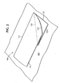
- Figure 2 depicts a schematic perspective view of an exemplary embodiment of the present invention, with the invention in the fully stowed position.
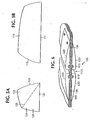
- Figure 3A depicts a side elevational view of an exemplary embodiment of the present invention, with the invention in the fully deployed position.
- Figure 3B depicts a side elevational view of an exemplary embodiment of the present invention, with the invention in the fully stowed position.
- Figure 4 depicts a top view of an exemplary embodiment of the present invention, with the invention in the fully deployed position.
- Figures 5A and 5B depict plan views of exemplary embodiments of second surface 110 and first surface 120 in unassembled form.
- Figure 6 depicts an exemplary mechanism for the joinder of panel 124 with panel 125.
- the term "reference" in its broadest sense means three non-colinear spatial points that define a geometrical plane (which may or may not have a physical counterpart) to which the present invention, assembly 100, can be secured.
- the physical counterpart for the reference can be the side, rear, front, top, bottom, beginning or end of an object, a portion of the surface of an object, two pipes joined by a right angle bend (the plane that they define being the reference), the earth's surface, the blunt end of an instrument or tool, three vertically-placed rods or poles (the plane defined by their three ends being the reference), and so on, depending upon the specific application or use to which the present invention is put.
- assembly 100 includes two principal components, a first surface 120 and a second surface 110.
- surfaces 110 and 120 When folded or stowed, surfaces 110 and 120 are generally planar in geometry, although as described below they each assume a curvature when deployed.
- the first surface 120 and second surface 110 are each semi-rigid in construction.
- a surface or panel is semi-rigid when it is of such thickness and material properties that, when flat, its bending stiffness and strength are low enough to permit the panel to bend elastically, without permanent deformation, to a radius of the same order of magnitude as the panel's width or height, and yet, when so bent elastically, the panel has sufficient resistance to buckling to enable it to resist load as a shell structure.
- each of first surface 120 and second surface 110 can be formed from a sheet of material such as sheet polypropylene.
- First surface 120 includes a terminal portion 121 that is depicted as a linear edge of surface 120, although it is not essential to this invention that portion 121 be linear.
- First surface 120 is secured to the reference 300 (in this case at terminal portion 121) in a manner which permits surface 120 to rotate approximately about the axis defined by the intersection of first surface 120 and reference 300.
- the terminal portion 121 of first surface 120 is secured to the reference 300 by any suitable feature or mechanism that will accord it the aforementioned rotational degree of freedom, such as by mechanical hinges.
- any feature or mechanism permitting such a rotational degree of freedom is suitable for use in the present invention, and that such a feature or mechanism need not be secured to terminal portion 121.
- second surface 110 includes a terminal potion 111 that is depicted as a linear edge of surface 110, although it is not essential to this invention that portion 111 be linear.
- Second surface 110 is secured to the reference 300 (in this case at terminal portion 111) in a manner which permits surface 110 to rotate approximately about the axis defined by the intersection of second surface 110 and reference 300.
- the terminal portion 111 of second surface 110 is secured to the reference 300 by any suitable mechanism that will accord it the aforementioned rotational degree of freedom, such as by mechanical hinges.
- any mechanism permitting such a rotational degree of freedom is suitable for use in the present invention, and that such a mechanism need not be secured to terminal portion 111.
- first surface 120 has a joint structure 123 spanning first surface 120 from the intersection of terminal portion 121 and curved edge 122 to, in this case, the diagonally opposite corner of first surface 120.
- the purpose of joint structure 123 is to allow the two parts of surface 120, specifically center panel 124 and side panel 125, to fold together when assembly 100 is stowed. Accordingly, while shown in Figure 5A to span surface 120 diagonally, orientation of joint structure 123 is preferably in accordance with the orientation that will most easily permit panels 124, 125 of first surface 120 to fold together and against second surface 110 in a compact manner without significantly stressing or bending the components, or requiring undue force to hold the folded assembly together.
- Joint structure 123 allows rotation of panels 124,125 relative to each other, while also permitting bending of the joint structure 123 as such rotation proceeds. While depicted as linear, joint structure 123 optionally can be curved, as a means for imparting more shape.
- a joint structure mechanism suitable for joint structure 123 is depicted in Figure 6 .
- one end of an elastomeric member 1123 is clamped between parts 620, 625 of securing member 615, and the other end of elastomeric member 1123 is clamped between parts 635, 640 of securing member 630.
- Securing members 615 and 630 which can be formed of molded polypropylene or other suitable material, are in turn respectively joined to parts 124 and 125 in any suitable manner, such as by rivets, welds, nuts and bolts, or the like.
- Elastomeric member 1123 or securing members 615 and 630 (or all) can be continuous in length, or interrupted, as is preferred.
- joint structure 123 can be a series of interrupted hinges spaced along the length of the intersection of panels 124, 125, as well as other mechanisms providing a similar function.
- second surface 110 has a curved edge 112 and first surface 120 has a curved edge 122.
- edges 112 and 122 are joined along their lengths by a joint structure 133 that allows rotation of surface 120 relative to surface 110 about the intersection of edges 112, 122, while also permitting bending of the joint structure 133 as such rotation proceeds.
- the joint structure 133 can be as depicted in Figure 6 .
- joint structure 133 can be a series of interrupted hinges along the length of the intersection of curves 112, 122, as well as other mechanisms providing a similar function.
- first surface 120 is positioned adjacent to the reference 300, and the upper portion of second surface 110 is positioned adjacent to the first surface 120.
- the two panels 124, 125 are in a folded state, with panel 124 sandwiched between panel 125 and the reference 300, and panel 125 sandwiched between second surface 110 and panel 124.
- Deployment commences by simply rotating second surface 110 out away from the reference 300, as a result of which first surface 120 starts to deploy. As this operation proceeds, the internal angle between surface 110 and panel 125 starts to open up, which in turn causes the region of surface 120 proximate to curved edge 122 to be urged into a downwardly curved shape, in seeking to conform to the curvature of curved edge 112. Likewise, the region of second surface 110 proximate to curved edge 112 is urged into a curved shape, in seeking to conform to the curvature of curved edge 122.
- first surface 120 is applied to first surface 120 in a manner causing first surface 120 to elastically buckle outward along the length of joint structure 123, with the result that panels 124, 125 are made locally co-planar in the region of joint structure 123, while the buckling action causes surface 120 to assume a curved shape.
- a force may be applied in the region of the anti-node of the primary buckling mode of first surface 120, in a direction generally normal to the plane of surface 120.
- the result of surface 120 buckling outward is to "lock" joint structure 123 in the open position, until another force is applied to cause structure 123 to buckle back into its original shape, thus freeing up joint structure 123 to rotate.
- the rigidity of fairing assembly 100 can be enhanced by tensioning inward the free edges of second surface 110 and first surface 120 during or subsequent to their deployment.
- tensioning mechanism a set of two cables 641 and 643, which are used to provide - the requisite tensioning. These cables 641 and 643 can be tensioned after deployment of assembly 100.
- the tensioning mechanism can be designed to cause tensioning in a passive manner, such that deployment of the surfaces 110, 120 by itself causes the tensioning mechanism to operate and, in turn, bend the surfaces in an appropriate manner.
- tensioning of cables 641 and 643 can be accomplished by securing them to reference 300 at an appropriate length. By doing so, cables 641 and 643 assume a tensioned state after partial deployment of surfaces 110, 120, and further deployment of the surfaces to a fully deployed state causes the fairing surfaces to bend to an appropriate degree.
- a similar passive tensioning function can be achieved by using other suitable tensioning mechanism designs, such as designs employing rods, levers, etc., as the primary elements, depending upon the particular application, as would be evident to a person of ordinary skill in the art.
- deployment and folding of surfaces 120 and 110 can be accomplished either manually, or using deployment/stowage mechanisms.
- deployment/stowage mechanisms are set forth in U.S. application 10/323,700, filed December 19, 2002 , naming the same inventors as herein and entitled “Deployable Vehicle Fairing Structure” (attorney docket no. 02916.000001), the contents of which are incorporated by reference herein.
- the tensioning and deployment/stowage functions can be accomplished using a single mechanism, as more fully described in the foregoing U.S. application 10/323,700, filed December 19, 2002 , naming the same inventors as herein and entitled “Deployable Vehicle Fairing Structure” (attorney docket no. 02916.000001), whose contents are incorporated by reference herein.
Landscapes
- Engineering & Computer Science (AREA)
- Architecture (AREA)
- Transportation (AREA)
- Structural Engineering (AREA)
- Chemical & Material Sciences (AREA)
- Combustion & Propulsion (AREA)
- Civil Engineering (AREA)
- Mechanical Engineering (AREA)
- Aerials With Secondary Devices (AREA)
- Tents Or Canopies (AREA)
- Superstructure Of Vehicle (AREA)
- Earth Drilling (AREA)
- Massaging Devices (AREA)
- Road Paving Structures (AREA)
Claims (2)
- Structure déployable comprenant :une première surface semi-rigide (120) dotée d'un premier bord (121), un deuxième bord et un troisième bord généralement non-linéaire (122) qui relie le premier et le deuxième bord, la ligne de corde du troisième bord généralement non-linéaire faisant un angle inférieur à un angle droit avec le premier bord, la première surface semi-rigide étant fixée de façon rotative à une référence (300) au niveau du premier bord (121) pour permettre la première surface semi-rigide (120) d'adopter une première position et une deuxième position, et la première surface semi-rigide (120) comprenant deux panneaux reliés (124, 125) pour permettre à la première surface semi-rigide (120) d'être pliée lorsqu'elle se trouve à la première position, et à être dépliée lorsqu'elle elle se trouve à la deuxième position ;une deuxième surface semi-rigide (110) présentant un quatrième bord (111), un cinquième bord et un sixième bord généralement non-linéaire (112) relié au quatrième (111) et au cinquième bord, la ligne de corde du sixième bord généralement non-linéaire formant un angle inférieur à un angle droit avec le quatrième bord (111), la deuxième surface semi-rigide étant fixée de façon rotative à la référence (300) au niveau du quatrième bord (111) pour permettre à la deuxième surface semi-rigide (110) d'adopter une première position et une deuxième position ; etla première (120) et la deuxième (110) surface semi- rigide étant reliées ensemble au niveau de leur troisième (122) et sixième (112) bord généralement non-linéaire pour permettre à la première (120) et la deuxième (110) surface semi-rigide de se plier approximativement ensemble lorsque la première (120) et la deuxième (110) surface semi-rigide se trouvent à leurs premières positions.
- La structure selon la revendication 1, comprenant en outre un mécanisme de mise sous tension (641, 643) fixé à la première surface semi-rigide (120) et à la deuxième surface semi-rigide (110), et destiné à être fixé à la référence (300).
Applications Claiming Priority (3)
| Application Number | Priority Date | Filing Date | Title |
|---|---|---|---|
| US10/323,693 US6915611B2 (en) | 2002-12-19 | 2002-12-19 | Deployable structure |
| US323693 | 2002-12-19 | ||
| PCT/US2003/040773 WO2004056643A2 (fr) | 2002-12-19 | 2003-12-19 | Structure deployable |
Publications (2)
| Publication Number | Publication Date |
|---|---|
| EP1578657A2 EP1578657A2 (fr) | 2005-09-28 |
| EP1578657B1 true EP1578657B1 (fr) | 2009-06-10 |
Family
ID=32593272
Family Applications (1)
| Application Number | Title | Priority Date | Filing Date |
|---|---|---|---|
| EP03813824A Expired - Lifetime EP1578657B1 (fr) | 2002-12-19 | 2003-12-19 | Structure deployable |
Country Status (8)
| Country | Link |
|---|---|
| US (1) | US6915611B2 (fr) |
| EP (1) | EP1578657B1 (fr) |
| JP (1) | JP2006510830A (fr) |
| AT (1) | ATE433407T1 (fr) |
| AU (1) | AU2003303203A1 (fr) |
| CA (1) | CA2511251A1 (fr) |
| DE (1) | DE60327947D1 (fr) |
| WO (1) | WO2004056643A2 (fr) |
Families Citing this family (24)
| Publication number | Priority date | Publication date | Assignee | Title |
|---|---|---|---|---|
| US7380868B2 (en) * | 2005-06-29 | 2008-06-03 | Thomas Scott Breidenbach | Aerodynamic drag reducing apparatus |
| US8627738B2 (en) * | 2005-06-29 | 2014-01-14 | Thomas Scott Breidenbach | Linear-curvilinear actuating apparatus with rotating joints |
| US7845708B2 (en) | 2007-06-06 | 2010-12-07 | Adaptive Aerodynamic, Llc | Aerodynamic drag reducing apparatus |
| US7618086B2 (en) | 2005-12-01 | 2009-11-17 | Thomas Scott Breidenbach | Aerodynamic drag reducing apparatus |
| US8100461B2 (en) | 2007-05-17 | 2012-01-24 | Advanced Transit Dynamics, Inc. | Rear-mounted aerodynamic structure for truck cargo bodies |
| US8360509B2 (en) | 2007-05-17 | 2013-01-29 | Advanced Transit Dynamics, Inc. | Rear-mounted aerodynamic structure for truck cargo bodies |
| WO2009102695A2 (fr) * | 2008-02-12 | 2009-08-20 | Aero Industries, Inc. | Dispositif de réduction de traînée à auto-déploiement |
| US7857376B2 (en) | 2008-02-21 | 2010-12-28 | Adaptive Aerodynamic, Llc | Aerodynamic drag reducing apparatus |
| US7958966B2 (en) * | 2009-03-31 | 2011-06-14 | Paccar Inc | Exhaust stack fairing |
| MX2011010739A (es) | 2009-04-16 | 2012-01-30 | Wabash National Lp | Faldon lateral y sistema de cable lateral antiempotramiento para un remolque. |
| US8770650B1 (en) | 2010-03-10 | 2014-07-08 | Jon Andrew Brosseau | Variable geometry aerodynamic fairing for reducing base drag of tractor trailers |
| WO2013043890A1 (fr) | 2011-09-20 | 2013-03-28 | Advanced Transit Dynamics, Inc. | Structure aérodynamique rétractable à montage arrière pour corps de chargement |
| US9440689B1 (en) | 2011-09-20 | 2016-09-13 | Stemco Lp | Aerodynamic structures secured to the underbody of cargo bodies |
| EP2771231A4 (fr) | 2011-10-27 | 2016-01-06 | Advanced Transit Dynamics Inc | Structures aérodynamiques à montage arrière pour carrosseries pour marchandises |
| MX2013003099A (es) | 2012-03-21 | 2014-01-09 | Wabash National Lp | Sistema de faldon lateral plegable para un remolque. |
| BR112015000663A2 (pt) | 2012-07-11 | 2017-06-27 | Advanced Transit Dynamics Inc | estruturas aerodinâmicas retráteis para corpos de carga e métodos para o controle do posicionamento das mesmas |
| US9919750B2 (en) | 2013-08-15 | 2018-03-20 | Wabash National, L.P. | Side skirt system for reducing drag |
| US9409610B2 (en) | 2014-03-11 | 2016-08-09 | Wabash National, L.P. | Side skirt system for a trailer |
| US9688320B2 (en) | 2014-10-29 | 2017-06-27 | Wabash National, L.P. | Side skirt system for a trailer |
| US12005969B2 (en) | 2016-04-07 | 2024-06-11 | Fleetaero, Llc | Vehicle aerodynamic improvement apparatus and system |
| US10343731B2 (en) | 2016-09-30 | 2019-07-09 | Wabash National, L.P. | Skirt system mount bracket assembly |
| US10549797B2 (en) | 2017-04-20 | 2020-02-04 | Wabash National, L.P. | Side underride guard |
| US10946824B2 (en) | 2017-09-13 | 2021-03-16 | Wabash National, L.P. | Side underride guard |
| US10940817B2 (en) | 2018-02-21 | 2021-03-09 | Wabash National, L.P. | Side underride guard |
Family Cites Families (46)
| Publication number | Priority date | Publication date | Assignee | Title |
|---|---|---|---|---|
| US2737411A (en) | 1952-08-21 | 1956-03-06 | Ralph B Potter | Inflatable streamlining apparatus for vehicle bodies |
| US2982290A (en) | 1958-01-08 | 1961-05-02 | Hunziker Walter Rudolf | Portable prefabricated shelter |
| US3206100A (en) | 1963-01-07 | 1965-09-14 | Wenger Harry | Packaging box |
| US3371453A (en) | 1964-08-03 | 1968-03-05 | Dehavilland Aircraft Canada | Cassette stem device |
| US3533202A (en) | 1968-12-13 | 1970-10-13 | Sunbird Ind Inc | Modular shelter or building |
| US3534514A (en) | 1968-12-13 | 1970-10-20 | Sunbird Ind Inc | Shelter using semi-rigid flexed walls |
| US3657753A (en) | 1970-09-29 | 1972-04-25 | Leo J Le Blanc Sr | Folding inflatable surfboard |
| US3721027A (en) | 1971-06-22 | 1973-03-20 | Shen & Slavsky Inc | New style picture frame panel |
| FR2145032A5 (fr) | 1971-07-07 | 1973-02-16 | Torrix Sa Ets | |
| US3774309A (en) | 1972-06-19 | 1973-11-27 | N Leopoldi | Steel measuring tape holder |
| US4145850A (en) * | 1973-09-17 | 1979-03-27 | Runyon John F | Folding modular building structure |
| US4036519A (en) | 1974-08-23 | 1977-07-19 | Aerospan Corporation | Streamlining apparatus for articulated road vehicle |
| US4006932A (en) | 1975-07-21 | 1977-02-08 | The United States Of America As Represented By The Secretary Of The Department Of Transportation | Inflatable drag reducer for land vehicles |
| US4030779A (en) | 1976-03-18 | 1977-06-21 | Johnson David W | Inflatable streamlining structure for vehicles |
| US4088362A (en) | 1976-09-16 | 1978-05-09 | Mollura Carlos A | Inflatable aerodynamic nose cone |
| US4142755A (en) | 1977-08-12 | 1979-03-06 | Keedy Edgar L | Vehicle drag reducer |
| US4153288A (en) | 1977-09-26 | 1979-05-08 | Donna M. Mueller | Folding air deflector |
| US4257641A (en) * | 1979-05-25 | 1981-03-24 | Keedy Edgar L | Vehicle drag reducer |
| US4419994A (en) | 1980-07-03 | 1983-12-13 | Racal Safety Limited | Respirators |
| US4451074A (en) | 1981-11-09 | 1984-05-29 | Barry Scanlon | Vehicular airfoils |
| US4818015A (en) | 1981-11-09 | 1989-04-04 | Scanlon Barry F | Vehicular airfoils |
| US4458936A (en) | 1981-12-23 | 1984-07-10 | Mulholland Frank J | Drag reducing fairing for trucks, trailers and cargo containers |
| US4424929A (en) * | 1982-03-16 | 1984-01-10 | Power-Wire Fastener Systems, Inc. | Clip magazine feed for fastener driving tools |
| US4601508A (en) | 1984-06-18 | 1986-07-22 | Kerian Paul D | Streamlining appendage for vehicles |
| US4702509A (en) | 1986-05-27 | 1987-10-27 | Elliott Sr Morris C | Long-haul vehicle streamline apparatus |
| US4688841A (en) | 1986-06-10 | 1987-08-25 | Moore Mark A | Drag reduction device for tractor-trailers |
| US4741569A (en) | 1987-03-04 | 1988-05-03 | Sutphen Paul F | Inflatable drag reducer for land transport vehicles |
| JPS63301186A (ja) * | 1987-05-26 | 1988-12-08 | ラフリス ゼイン | 運輸手段 |
| US4978162A (en) | 1989-11-29 | 1990-12-18 | Labbe Francois P | Drag reducer for rear end of vehicle |
| US5058945A (en) | 1990-06-08 | 1991-10-22 | Elliott Sr Morris C | Long-haul vehicle streamline apparatus |
| DE4021337A1 (de) | 1990-07-04 | 1992-01-09 | Anton Dipl Ing Dr Lechner | Vorrichtung zur reduzierung des stroemungswiderstandes eines nutzfahrzeuges |
| SE468565B (sv) * | 1990-09-18 | 1993-02-08 | Christer Zarelius | Bandformat boejbart organ |
| US5240306A (en) | 1992-08-05 | 1993-08-31 | Flemming George M | Aerodynamic drag reduction fairing |
| US5498059A (en) | 1994-09-28 | 1996-03-12 | Switlik; Stanley | Apparatus for reducing drag |
| GB9517500D0 (en) * | 1995-08-25 | 1995-10-25 | J T Inglis & Sons Limited | Shelter structures |
| US5685597A (en) | 1995-11-27 | 1997-11-11 | Reid; James Charles | Vehicle wind deflector |
| US5947548A (en) | 1996-07-29 | 1999-09-07 | Carper; Herbert J. | Aerodynamic drag reducing geometry for land-based vehicles |
| US6126239A (en) * | 1997-04-14 | 2000-10-03 | Chameleon Studio, Inc. | Ready to assemble furniture construction including frameless self-supporting panel members |
| US5823610A (en) | 1997-10-22 | 1998-10-20 | James C. Ryan | Drag reducing apparatus for a vehicle |
| DE19804435C2 (de) | 1998-02-05 | 2000-03-16 | Merz Sauter Zimmermann Gmbh | Entfaltbare Dachkonstruktion |
| US6092861A (en) | 1999-07-26 | 2000-07-25 | Whelan; William | Air drag reduction unit for vehicles |
| US6309010B1 (en) | 1999-09-29 | 2001-10-30 | W. David Whitten | Collapsible streamlined tail for trucks and trailers |
| GB0002519D0 (en) * | 2000-02-03 | 2000-03-29 | Univ Dundee | Cantilever support and erectable structures |
| US6428084B1 (en) * | 2001-04-24 | 2002-08-06 | Richard M. Liss | Fuel-efficient tractor-trailer system |
| US6467833B1 (en) | 2001-09-27 | 2002-10-22 | R. H. Travers Company | Drag reducer |
| US6485087B1 (en) * | 2001-11-16 | 2002-11-26 | Maka Innovation Technologique Inc. | Air drag reducing apparatus |
-
2002
- 2002-12-19 US US10/323,693 patent/US6915611B2/en not_active Expired - Fee Related
-
2003
- 2003-12-19 WO PCT/US2003/040773 patent/WO2004056643A2/fr active Application Filing
- 2003-12-19 JP JP2004562352A patent/JP2006510830A/ja not_active Ceased
- 2003-12-19 CA CA002511251A patent/CA2511251A1/fr not_active Abandoned
- 2003-12-19 AT AT03813824T patent/ATE433407T1/de not_active IP Right Cessation
- 2003-12-19 EP EP03813824A patent/EP1578657B1/fr not_active Expired - Lifetime
- 2003-12-19 AU AU2003303203A patent/AU2003303203A1/en not_active Abandoned
- 2003-12-19 DE DE60327947T patent/DE60327947D1/de not_active Expired - Fee Related
Also Published As
| Publication number | Publication date |
|---|---|
| EP1578657A2 (fr) | 2005-09-28 |
| CA2511251A1 (fr) | 2004-07-08 |
| AU2003303203A1 (en) | 2004-07-14 |
| JP2006510830A (ja) | 2006-03-30 |
| ATE433407T1 (de) | 2009-06-15 |
| WO2004056643A2 (fr) | 2004-07-08 |
| WO2004056643A3 (fr) | 2004-08-05 |
| US20040118055A1 (en) | 2004-06-24 |
| DE60327947D1 (de) | 2009-07-23 |
| US6915611B2 (en) | 2005-07-12 |
Similar Documents
| Publication | Publication Date | Title |
|---|---|---|
| EP1578657B1 (fr) | Structure deployable | |
| US6799791B2 (en) | Deployable vehicle fairing structure | |
| US5038812A (en) | Quickly erectable, quickly collapsible, self supporting portable structure | |
| US20130186011A1 (en) | Collapsible longeron structures | |
| US10223939B2 (en) | Self-erectable display and automatic locking mechanism for a self-erectable display | |
| US7134230B1 (en) | Stand-up display | |
| US20170130875A1 (en) | Coilable extendible member and methods | |
| EP1228283B1 (fr) | Structure portable | |
| US8820005B2 (en) | Portable shelter structure and manufacturing process | |
| US6601598B2 (en) | Collapsible shelter | |
| US20030182878A1 (en) | Flat folding tube | |
| US5407007A (en) | Motorized canister awning | |
| US6988505B2 (en) | Expandable canopy | |
| US3408029A (en) | Self-locking, self-actuating, light-weight folding strut | |
| CN110745257A (zh) | 一种可折叠支撑结构 | |
| US3474804A (en) | Beach shelter | |
| US9140031B2 (en) | Modular tent door assembly with collapsible frame | |
| WO2018048601A1 (fr) | Système et procédé d'abri de véhicule extensible | |
| JP2727892B2 (ja) | 折れ曲り展開機構 | |
| WO1994013910A1 (fr) | Structure et procedes de fabrication | |
| CN211479556U (zh) | 折叠装置及电子设备 | |
| JPS5913863Y2 (ja) | 折畳み傘 | |
| JP2579513Y2 (ja) | 折りたたみ式簡易建物 | |
| JP2007070910A (ja) | 簡易折畳式フレーム構造体 | |
| US20120205370A1 (en) | Collapsible containment structure |
Legal Events
| Date | Code | Title | Description |
|---|---|---|---|
| PUAI | Public reference made under article 153(3) epc to a published international application that has entered the european phase |
Free format text: ORIGINAL CODE: 0009012 |
|
| 17P | Request for examination filed |
Effective date: 20050718 |
|
| AK | Designated contracting states |
Kind code of ref document: A2 Designated state(s): AT BE BG CH CY CZ DE DK EE ES FI FR GB GR HU IE IT LI LU MC NL PT RO SE SI SK TR |
|
| AX | Request for extension of the european patent |
Extension state: AL LT LV MK |
|
| DAX | Request for extension of the european patent (deleted) | ||
| REG | Reference to a national code |
Ref country code: HK Ref legal event code: DE Ref document number: 1082480 Country of ref document: HK |
|
| RAP1 | Party data changed (applicant data changed or rights of an application transferred) |
Owner name: AEROFFICIENT, LLC |
|
| GRAP | Despatch of communication of intention to grant a patent |
Free format text: ORIGINAL CODE: EPIDOSNIGR1 |
|
| GRAC | Information related to communication of intention to grant a patent modified |
Free format text: ORIGINAL CODE: EPIDOSCIGR1 |
|
| GRAS | Grant fee paid |
Free format text: ORIGINAL CODE: EPIDOSNIGR3 |
|
| GRAA | (expected) grant |
Free format text: ORIGINAL CODE: 0009210 |
|
| AK | Designated contracting states |
Kind code of ref document: B1 Designated state(s): AT BE BG CH CY CZ DE DK EE ES FI FR GB GR HU IE IT LI LU MC NL PT RO SE SI SK TR |
|
| REG | Reference to a national code |
Ref country code: GB Ref legal event code: FG4D |
|
| REG | Reference to a national code |
Ref country code: CH Ref legal event code: EP |
|
| REG | Reference to a national code |
Ref country code: IE Ref legal event code: FG4D |
|
| REF | Corresponds to: |
Ref document number: 60327947 Country of ref document: DE Date of ref document: 20090723 Kind code of ref document: P |
|
| PG25 | Lapsed in a contracting state [announced via postgrant information from national office to epo] |
Ref country code: AT Free format text: LAPSE BECAUSE OF FAILURE TO SUBMIT A TRANSLATION OF THE DESCRIPTION OR TO PAY THE FEE WITHIN THE PRESCRIBED TIME-LIMIT Effective date: 20090610 Ref country code: FI Free format text: LAPSE BECAUSE OF FAILURE TO SUBMIT A TRANSLATION OF THE DESCRIPTION OR TO PAY THE FEE WITHIN THE PRESCRIBED TIME-LIMIT Effective date: 20090610 |
|
| NLV1 | Nl: lapsed or annulled due to failure to fulfill the requirements of art. 29p and 29m of the patents act | ||
| PG25 | Lapsed in a contracting state [announced via postgrant information from national office to epo] |
Ref country code: SE Free format text: LAPSE BECAUSE OF FAILURE TO SUBMIT A TRANSLATION OF THE DESCRIPTION OR TO PAY THE FEE WITHIN THE PRESCRIBED TIME-LIMIT Effective date: 20090910 Ref country code: NL Free format text: LAPSE BECAUSE OF FAILURE TO SUBMIT A TRANSLATION OF THE DESCRIPTION OR TO PAY THE FEE WITHIN THE PRESCRIBED TIME-LIMIT Effective date: 20090610 Ref country code: SI Free format text: LAPSE BECAUSE OF FAILURE TO SUBMIT A TRANSLATION OF THE DESCRIPTION OR TO PAY THE FEE WITHIN THE PRESCRIBED TIME-LIMIT Effective date: 20090610 |
|
| PG25 | Lapsed in a contracting state [announced via postgrant information from national office to epo] |
Ref country code: ES Free format text: LAPSE BECAUSE OF FAILURE TO SUBMIT A TRANSLATION OF THE DESCRIPTION OR TO PAY THE FEE WITHIN THE PRESCRIBED TIME-LIMIT Effective date: 20090921 Ref country code: RO Free format text: LAPSE BECAUSE OF FAILURE TO SUBMIT A TRANSLATION OF THE DESCRIPTION OR TO PAY THE FEE WITHIN THE PRESCRIBED TIME-LIMIT Effective date: 20090610 Ref country code: CZ Free format text: LAPSE BECAUSE OF FAILURE TO SUBMIT A TRANSLATION OF THE DESCRIPTION OR TO PAY THE FEE WITHIN THE PRESCRIBED TIME-LIMIT Effective date: 20090610 Ref country code: EE Free format text: LAPSE BECAUSE OF FAILURE TO SUBMIT A TRANSLATION OF THE DESCRIPTION OR TO PAY THE FEE WITHIN THE PRESCRIBED TIME-LIMIT Effective date: 20090610 |
|
| PG25 | Lapsed in a contracting state [announced via postgrant information from national office to epo] |
Ref country code: SK Free format text: LAPSE BECAUSE OF FAILURE TO SUBMIT A TRANSLATION OF THE DESCRIPTION OR TO PAY THE FEE WITHIN THE PRESCRIBED TIME-LIMIT Effective date: 20090610 Ref country code: BE Free format text: LAPSE BECAUSE OF FAILURE TO SUBMIT A TRANSLATION OF THE DESCRIPTION OR TO PAY THE FEE WITHIN THE PRESCRIBED TIME-LIMIT Effective date: 20090610 |
|
| PG25 | Lapsed in a contracting state [announced via postgrant information from national office to epo] |
Ref country code: BG Free format text: LAPSE BECAUSE OF FAILURE TO SUBMIT A TRANSLATION OF THE DESCRIPTION OR TO PAY THE FEE WITHIN THE PRESCRIBED TIME-LIMIT Effective date: 20090910 Ref country code: PT Free format text: LAPSE BECAUSE OF FAILURE TO SUBMIT A TRANSLATION OF THE DESCRIPTION OR TO PAY THE FEE WITHIN THE PRESCRIBED TIME-LIMIT Effective date: 20091010 |
|
| PLBE | No opposition filed within time limit |
Free format text: ORIGINAL CODE: 0009261 |
|
| STAA | Information on the status of an ep patent application or granted ep patent |
Free format text: STATUS: NO OPPOSITION FILED WITHIN TIME LIMIT |
|
| PG25 | Lapsed in a contracting state [announced via postgrant information from national office to epo] |
Ref country code: DK Free format text: LAPSE BECAUSE OF FAILURE TO SUBMIT A TRANSLATION OF THE DESCRIPTION OR TO PAY THE FEE WITHIN THE PRESCRIBED TIME-LIMIT Effective date: 20090610 |
|
| 26N | No opposition filed |
Effective date: 20100311 |
|
| PG25 | Lapsed in a contracting state [announced via postgrant information from national office to epo] |
Ref country code: MC Free format text: LAPSE BECAUSE OF NON-PAYMENT OF DUE FEES Effective date: 20100701 |
|
| REG | Reference to a national code |
Ref country code: CH Ref legal event code: PL |
|
| GBPC | Gb: european patent ceased through non-payment of renewal fee |
Effective date: 20091219 |
|
| REG | Reference to a national code |
Ref country code: FR Ref legal event code: ST Effective date: 20100831 |
|
| PG25 | Lapsed in a contracting state [announced via postgrant information from national office to epo] |
Ref country code: LI Free format text: LAPSE BECAUSE OF NON-PAYMENT OF DUE FEES Effective date: 20091231 Ref country code: FR Free format text: LAPSE BECAUSE OF NON-PAYMENT OF DUE FEES Effective date: 20091231 Ref country code: GR Free format text: LAPSE BECAUSE OF FAILURE TO SUBMIT A TRANSLATION OF THE DESCRIPTION OR TO PAY THE FEE WITHIN THE PRESCRIBED TIME-LIMIT Effective date: 20090911 Ref country code: IE Free format text: LAPSE BECAUSE OF NON-PAYMENT OF DUE FEES Effective date: 20091219 Ref country code: CH Free format text: LAPSE BECAUSE OF NON-PAYMENT OF DUE FEES Effective date: 20091231 |
|
| PG25 | Lapsed in a contracting state [announced via postgrant information from national office to epo] |
Ref country code: DE Free format text: LAPSE BECAUSE OF NON-PAYMENT OF DUE FEES Effective date: 20100701 |
|
| PG25 | Lapsed in a contracting state [announced via postgrant information from national office to epo] |
Ref country code: GB Free format text: LAPSE BECAUSE OF NON-PAYMENT OF DUE FEES Effective date: 20091219 |
|
| PG25 | Lapsed in a contracting state [announced via postgrant information from national office to epo] |
Ref country code: IT Free format text: LAPSE BECAUSE OF FAILURE TO SUBMIT A TRANSLATION OF THE DESCRIPTION OR TO PAY THE FEE WITHIN THE PRESCRIBED TIME-LIMIT Effective date: 20090610 |
|
| PG25 | Lapsed in a contracting state [announced via postgrant information from national office to epo] |
Ref country code: LU Free format text: LAPSE BECAUSE OF NON-PAYMENT OF DUE FEES Effective date: 20091219 |
|
| PG25 | Lapsed in a contracting state [announced via postgrant information from national office to epo] |
Ref country code: HU Free format text: LAPSE BECAUSE OF FAILURE TO SUBMIT A TRANSLATION OF THE DESCRIPTION OR TO PAY THE FEE WITHIN THE PRESCRIBED TIME-LIMIT Effective date: 20091211 |
|
| PG25 | Lapsed in a contracting state [announced via postgrant information from national office to epo] |
Ref country code: TR Free format text: LAPSE BECAUSE OF FAILURE TO SUBMIT A TRANSLATION OF THE DESCRIPTION OR TO PAY THE FEE WITHIN THE PRESCRIBED TIME-LIMIT Effective date: 20090610 |
|
| PG25 | Lapsed in a contracting state [announced via postgrant information from national office to epo] |
Ref country code: CY Free format text: LAPSE BECAUSE OF FAILURE TO SUBMIT A TRANSLATION OF THE DESCRIPTION OR TO PAY THE FEE WITHIN THE PRESCRIBED TIME-LIMIT Effective date: 20090610 |
|
| REG | Reference to a national code |
Ref country code: HK Ref legal event code: WD Ref document number: 1082480 Country of ref document: HK |