EP1578653B1 - Unterdruck-bremskraftverstärker und verfahren zu seiner herstellung - Google Patents
Unterdruck-bremskraftverstärker und verfahren zu seiner herstellung Download PDFInfo
- Publication number
- EP1578653B1 EP1578653B1 EP03789306.2A EP03789306A EP1578653B1 EP 1578653 B1 EP1578653 B1 EP 1578653B1 EP 03789306 A EP03789306 A EP 03789306A EP 1578653 B1 EP1578653 B1 EP 1578653B1
- Authority
- EP
- European Patent Office
- Prior art keywords
- piston
- reaction
- longitudinal end
- cage
- pressure chamber
- Prior art date
- Legal status (The legal status is an assumption and is not a legal conclusion. Google has not performed a legal analysis and makes no representation as to the accuracy of the status listed.)
- Expired - Lifetime
Links
- 238000000034 method Methods 0.000 title claims description 15
- 238000006243 chemical reaction Methods 0.000 claims description 91
- 238000004519 manufacturing process Methods 0.000 claims description 16
- 230000000284 resting effect Effects 0.000 claims description 4
- 239000000523 sample Substances 0.000 claims description 4
- 230000036316 preload Effects 0.000 description 6
- 239000004579 marble Substances 0.000 description 5
- 238000004891 communication Methods 0.000 description 4
- 238000006073 displacement reaction Methods 0.000 description 3
- 229910000838 Al alloy Inorganic materials 0.000 description 2
- 230000004913 activation Effects 0.000 description 2
- 230000006835 compression Effects 0.000 description 2
- 238000007906 compression Methods 0.000 description 2
- 238000009826 distribution Methods 0.000 description 2
- 239000000463 material Substances 0.000 description 2
- 238000005259 measurement Methods 0.000 description 2
- 239000010959 steel Substances 0.000 description 2
- 229910000851 Alloy steel Inorganic materials 0.000 description 1
- 229910000881 Cu alloy Inorganic materials 0.000 description 1
- 229910000831 Steel Inorganic materials 0.000 description 1
- 230000005540 biological transmission Effects 0.000 description 1
- 238000002788 crimping Methods 0.000 description 1
- 239000006185 dispersion Substances 0.000 description 1
- 238000001125 extrusion Methods 0.000 description 1
- 239000012530 fluid Substances 0.000 description 1
- 239000012528 membrane Substances 0.000 description 1
- 230000003797 telogen phase Effects 0.000 description 1
Images


Classifications
-
- B—PERFORMING OPERATIONS; TRANSPORTING
- B60—VEHICLES IN GENERAL
- B60T—VEHICLE BRAKE CONTROL SYSTEMS OR PARTS THEREOF; BRAKE CONTROL SYSTEMS OR PARTS THEREOF, IN GENERAL; ARRANGEMENT OF BRAKING ELEMENTS ON VEHICLES IN GENERAL; PORTABLE DEVICES FOR PREVENTING UNWANTED MOVEMENT OF VEHICLES; VEHICLE MODIFICATIONS TO FACILITATE COOLING OF BRAKES
- B60T13/00—Transmitting braking action from initiating means to ultimate brake actuator with power assistance or drive; Brake systems incorporating such transmitting means, e.g. air-pressure brake systems
- B60T13/10—Transmitting braking action from initiating means to ultimate brake actuator with power assistance or drive; Brake systems incorporating such transmitting means, e.g. air-pressure brake systems with fluid assistance, drive, or release
- B60T13/24—Transmitting braking action from initiating means to ultimate brake actuator with power assistance or drive; Brake systems incorporating such transmitting means, e.g. air-pressure brake systems with fluid assistance, drive, or release the fluid being gaseous
- B60T13/46—Vacuum systems
- B60T13/52—Vacuum systems indirect, i.e. vacuum booster units
- B60T13/573—Vacuum systems indirect, i.e. vacuum booster units characterised by reaction devices
- B60T13/575—Vacuum systems indirect, i.e. vacuum booster units characterised by reaction devices using resilient discs or pads
Definitions
- the present invention mainly relates to a pneumatic brake booster equipped with an emergency braking assistance device, to a method of manufacturing such a booster and to a device for implementing a booster. such a method. More particularly, the pneumatic brake booster equipped with an emergency braking assistance device makes it possible to increase the helper ratio beyond a certain force applied on the control rod.
- a pneumatic brake booster equipped with an emergency braking device is known from the document FR 2820388 A .
- the servomotor comprises, in known manner, an envelope formed by a first and a second shell in which is slidably mounted a skirt dividing the inside of the envelope into a low pressure chamber into a variable pressure chamber.
- a pneumatic piston disposed in the central portion of the skirt and integral with the skirt, has in its rear part a three-way valve actuated by an actuating rod connected to a brake pedal.
- the three-way valve communicates during a rest phase the low pressure chamber with the variable pressure chamber and during a braking phase interrupts the communication between the low pressure chamber and the braking chamber and sets communication the variable pressure chamber with the external environment at atmospheric pressure.
- the pneumatic brake booster also comprises a push rod actuating a piston of a master cylinder and capable of being displaced during a braking phase under the action of the actuating rod and the pneumatic piston.
- a reaction disc is disposed in a housing secured to the rear end of the push rod and comprises three forces, a first force from the actuating rod via a feeler, a second force from the piston. pneumatic and a third force from the master cylinder and called hydraulic reaction of the braking circuit, the reaction disc is made of a substantially incompressible material for example a rubber.
- the servomotor also comprises an emergency braking assistance device for modifying the assist ratio, advantageously to increase it.
- the ratio of the output force to the push rod and the input force applied to the control rod is referred to as the assist ratio.
- the assist ratio it is not necessary for comfort driving in which emergency braking is very infrequent to constantly have a high assist ratio.
- a servomotor comprising an emergency braking device allowing for a force exerted on the brake pedal greater than a predetermined value to increase the assistance ratio and thus to promote a rapid stop of the vehicle.
- the emergency braking device is disposed in the thrust rod in the receiving housing of the reaction disc, it comprises a resilient member deforming for a force to the brake pedal greater than the predetermined value and mounted in compression between a rear face of the push rod and a floating element in contact with the reaction disc, the reaction disc also being in contact with an annular ring surrounding the floating element without play and secured to the push rod.
- the elastic element is compressed allowing an axial displacement towards the front of the floating element and the reaction disk. to flow forward.
- This modifies the distribution of the reaction of the master cylinder transmitted to the plunger and consequently to the brake pedal and modifies the helper ratio.
- the preload of the elastic member or the spring of the emergency braking device precisely defines the threshold force beyond which the assist ratio is increased. It is therefore necessary to be able to precisely fix the preload of the spring.
- the adjustment of the spring preload is relatively imprecise since it is effected by means of wedges considering a given length of the spring.
- the value of the jump of the servomotor is determined by the relative position between the floating part and the annular ring, more particularly between the axial position of the face of the floating element in contact with the reaction disc and the face of the ring. annular in contact with the reaction disk, it is therefore necessary to be able to dispose with a known set the face of the floating element in contact with the reaction disk relative to the face of the annular ring in contact with the surrounding reaction disc.
- a servomotor comprising an emergency braking device whose characteristics are easily adjustable.
- the emergency braking device is in particular individually adjustable.
- the parameters to be adjusted are the activation force of said emergency braking assistance device and the value of the jump defined by the relative position of the floating element and the annular ring, the adjustment of the force of activation of the emergency braking assistance device being performed according to the stiffness of the spring that the device contains.
- the emergency braking assistance device comprises first axially axially deformable elements during manufacture of the booster for increasing the load of the spring until the desired load is reached and also comprising second plastically axially deformable elements allowing a relative displacement during manufacture of the rear face carried by the floating element and the rear face carried by the annular ring and thus to allow a precise jump adjustment.
- the main subject of the present invention is a pneumatic brake booster comprising a casing having a longitudinal axis in which a low pressure chamber and a variable pressure chamber are delimited by a movable wall carrying a pneumatic piston in its seat. central part, a three-way valve arranged in the rear part of the pneumatic piston and controlled by an actuating rod, the three-way valve comprising a rebalancing valve between the low pressure chamber and the variable pressure chamber and a valve of high pressure supply of the variable pressure chamber, said supply valve having a valve seat carried by a first longitudinal end of a plunger and receiving a longitudinal end of the actuating rod, said plunger bearing a probe perpendicular to the axis longitudinal to a second longitudinal end opposite the first longitudinal end and coming into contact with a face of a reaction disk during a braking phase, said reaction disk being disposed in a housing secured to a push rod actuating a master cylinder, said housing comprising a pneumatic brake assist device provided with a cage secured to the thrust rod
- the present invention also relates to a booster characterized in that the elastic means is a helical spring.
- the present invention also relates to a booster characterized in that said first means are formed by a ring.
- the present invention also relates to a booster characterized in that said first means are formed by an annular projection integrally formed with the ring annular extending axially forward of the front face of the annular ring.
- the present invention also relates to a booster characterized in that said first means are formed by an annular projection integral with the fin and extending axially rearward of the rear face of the fin.
- the present invention also relates to a booster characterized in that the second means are formed by a ring disposed between the front face of the annular ring and the rear face of an inner bearing of the cage.
- the present invention also relates to a booster characterized in that the second means are formed by an annular projection integrally formed with the annular ring extending from the front face of the annular ring axially towards an inner bearing of the cage.
- the present invention also relates to a booster characterized in that the cage comprises a sleeve closed at a first longitudinal end before a lid integral with the push rod, the second means being disposed between the longitudinal end of the sleeve and a sleeve. back side of the lid.
- the present invention also relates to a booster characterized in that the second means are formed by an annular projection integral with the sleeve and extending axially towards the lid.
- the present invention also relates to a booster characterized in that said lid is secured to the sleeve by means of a radially external annular extension relative to the annular projection forming the second means and being folded by plastic deformation on the front face of the lid .
- the present invention also relates to a device for implementing the preliminary step of the method according to the present invention for manufacturing a pneumatic brake booster comprising a longitudinal axis envelope in which are delimited in a sealed manner a low pressure chamber and a variable pressure chamber by a movable wall carrying a pneumatic piston in its central part, a three-way valve arranged in the rear part of the pneumatic piston and controlled by an actuating rod, the three-way valve comprising a rebalancing valve between the low pressure chamber and the variable pressure chamber and a high pressure supply valve of the variable pressure chamber, said supply valve having a valve seat carried by a first longitudinal end of a plunger and receiving a longitudinal end of the actuating rod, said di plunger stripper having a feeler perpendicular to the longitudinal axis at a second longitudinal end opposite the first longitudinal end and coming into contact with a face of a reaction disk during a braking phase, said reaction disk being disposed in a housing secured to a push rod actuating a master cylinder, said
- the present invention also relates to a device for implementing the next step of the method according to the present invention characterized in that it comprises a third element and a fourth element movable along the longitudinal axis relative to the third element, said third element comprising an annular bearing surface of the front face of the annular ring and means for detecting the force applied to the reaction piston by the elastic means, the fourth element comprising a force application surface deforming the cage so as to plastically deform the second means during an axial displacement of the fourth element towards the third element so that the load of the elastic means is equal to the predetermined value.
- the back of an element denotes the portion of the element oriented towards the control rod and the front of the element indicates the part of the part facing the push rod.
- plastically deformable element an element whose shape is changed due to the application of a minimum load during a manufacturing step, this shape being the final form of the element once mounted in the device it composes, the element no longer undergoing any load that can deform it in a non-temporary manner.
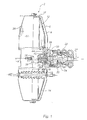
- a servomotor of known type of longitudinal axis X having an envelope 2 formed by a first and a second shells 4,6 defining an interior space.
- the servomotor also comprises a movable wall 12 sealingly dividing the interior space into a variable pressure rear chamber 8 and a low pressure front chamber 10.
- the movable wall 12 is formed by a skirt 14 and a flexible drop-down membrane 16 sealingly attached both to the skirt 14 on its outer periphery and to the casing 2 of the booster.
- the skirt 16 comprises a central orifice in which is fixedly mounted a pneumatic piston 18 receiving in its rear part a three-way valve 20 actuated by a control rod 27 connected to a brake pedal (not shown).
- the three-way valve 20 comprises a rebalancing valve 22 putting the front chamber 10 into communication at rest with the rear chamber and interrupting this communication during a braking phase, and a high-pressure pneumatic fluid supply valve 24, for example air at atmospheric pressure of the rear chamber 8.
- the front chamber is connected by a connector 26 to a source of low pressure, for example a vacuum pump.
- a source of low pressure for example a vacuum pump.
- control rod 27 The front longitudinal end of the control rod 27 is rotulatively received in a rear end of a plunger 28 which also forms a seat of the supply valve 24.
- the plunger distributor 28 has at its longitudinal end 30 a feeler capable of coming into contact with a rear face of a reaction disc 32 received in a cup-shaped housing 34 integral with a push rod 36, the rod of thrust coming to move a piston (not shown) of a master cylinder.
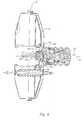
- the servomotor also comprises a braking assistance device D allowing for a pedal actuating force greater than a determined value to increase the jump of the servomotor.
- the device D forms the housing 34 for the reaction disc 32 and comprises a cage 38 of substantially U-shaped longitudinal section, the bottom of the U is fixedly connected to the push rod 36.
- An elastic means for example a helical spring 40 is mounted in compression between a rear face 41 of the bottom of the cage 38 and a floating element 42 or reaction piston closing the open rear end of the U in cooperation with an annular ring 44 surrounding the reaction piston 42 and fixedly mounted by compared to the cage 38.
- the reaction piston 42 comprises a first front portion 54 of smaller diameter, a second portion of larger diameter 56.
- the larger diameter portion 56 of outer diameter equal to the inside diameter of the ring 44 is slidably mounted in the ring annular.
- the reaction piston 42 also has an annular fin 60 extending radially outwardly from the second, smaller diameter portion 56.
- the fin 60 carries a bearing surface 62 for the rear longitudinal end of the spring 40 and a surface 64 before resting against a front face 66 of the annular ring 44.
- the cage 38 has a first front portion 46 of smaller diameter, a second rear portion 48 of larger diameter and connected to the weaker portion. diameter 46 by a radial extension 47 forming an inner radial surface for the front face 66 of the annular ring 44.
- the housing 34 of the reaction disc is formed by a rear section of the second larger diameter portion 48 and the rear face 50 of the ring 44 and a rear face 52 of the reaction piston 42.
- the ring 44 is secured to the cage 38 for example by crimping but we could consider the bonding.
- the reaction piston 42 remains stationary with respect to the annular ring 44 and the transmission of the reaction force to the plunger takes place in a known manner.
- first plastically deformable means 68 capable of adjusting the axial clearance j between the rear face 50 of the ring 44 and the rear face 52 of the reaction piston 42 are arranged between the front face 66 of the ring 44 and the rear face 62 of the fin 60.
- first means 68 formed by a plastically deformable ring 70 and made for example of steel or aluminum alloy.
- the rear face of the fin 60 advantageously comprises a shoulder 61 for transversely holding the ring 70.
- the clearance is adjusted between the rear faces 52 and 50 of the first means 68 formed by an annular projection on the rear face 62 of the fin 60 in a first example ( figure 5 ), or on the front face 66 of the annular ring 44 in a second example ( figure 6 ) and extending along the X axis respectively backwards and forwards.
- the projection is advantageously integral with the reaction piston 42 according to the first example or with the ring 44 according to the second example.
- the extension along the X axis of the first means 68 must be sufficient to connect the two surfaces between which they are interposed when the predetermined value Vj of the game j is reached.
- the device D advantageously comprises second plastically deformable means 74 making it possible to adjust the load of the elastic means 40 and this by modifying the distance separating the rear face 41 from the bottom of the cage 38 fixed to the push rod 36 and the front face 64 of the fin 60.
- the second means 74 are formed by a ring 76 plastically deformable and coming between a front face 66 of the annular ring and the inner bearing 47 of the cage 38, the ring 76 then forming an axial bearing means for the annular ring 44.
- the ring is advantageously made of a material having a high level of elongation at break for example steel, aluminum alloys or copper alloys.
- the second plastically deformable means 74 are an annular projection extending along the axis X of the rear face of the annular ring 44 according to the invention.
- a first example figure 5
- the cage 38 comprises a sleeve 381 closed at its longitudinal end before 383 by a cover 382 fixed to the sleeve 381 by deformation of a longitudinal extension 385 of the sleeve.
- the front longitudinal end 383 of the sleeve comprises an annular shoulder 384 on its inner periphery defining the longitudinal extension of smaller thickness 385 relative to the thickness of the sleeve and being folded over the periphery of the lid to maintain it.
- the second means 74 is then formed by an annular projection on the shoulder 384 and bearing on the rear face of the cover 382.
- the annular ring is advantageously integral with the sleeve 381, the reaction piston 42 is then mounted by the front longitudinal end of the sleeve 381 before being closed by the cover 382.
- the axial dimension of the second means 74 is determined so that the distance separating the two stops of the spring 40 before deformation of the second means 74 implies a load of the lower spring or equal to that required.
- the device D according to the present invention advantageously comprises the first 68 and the second 74 plastically deformable means. But it is understood that it is conceivable to provide a device comprising the first 68 or the second 74 plastically deformable means depending on the manufacturing and adjustment requirements.
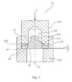
- a device AA for implementing step A of the method according to the present invention of X axis comprising a first element 202 for adjusting the clearance j to the value Vj between the rear surface 50 of the ring annular 44 and the rear face 52 of the reaction piston 42 and a second mobile element 204 for deforming the first plastically deformable means to definitively set the game j to the value Vj.
- the first element 202 is provided with a flat surface 206, for example a marble.
- the second element 204 comprises a receiving housing 208 formed by a non-through bore of inner diameter advantageously substantially equal to the diameter of a portion of the portion of smaller diameter and thus forming a lateral holding means.
- the open end of the bore 214 advantageously comprises a chamfer 212 in order to facilitate the positioning of the reaction piston 42.
- a bearing surface 210 perpendicular to the X axis surrounding the open end of the bore 214 is provided and cooperates with the front face 64 of the fin.
- the second element 204 is movable along the axis X to deform the first means 68 when it is moved in the direction of the arrow F.
- the device AA also applies to the other embodiments of the first means 68 represented in FIG. Figures 5 and 6 .
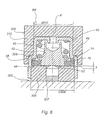
- a device BB for implementing step B of the method according to the present invention having an X axis comprising a third fixed element 302 and a fourth element 304 mobile in translation along the X axis so as to be able to get closer to the third element 302.
- the third element 302 comprises a tubular element 306 of outside diameter D306 at most equal to the inside diameter of the portion of larger diameter 48 of the cage 38.
- the third element 302 also comprises a force detector 307 disposed in the central passage of the 306 and in contact with the rear face 52 of the reaction piston 42 and for measuring the force applied by the spring 40 to the reaction piston 42.
- the force sensor measures a preload of the spring which corresponds to the preload of the spring in the mounting position plus a preload artificially caused by a predetermined clearance h for the measurement between the rear faces 52 of the reaction piston 42 and the front face of the the element 306.
- the fourth element 304 is movable in translation along the axis X and comprises a bearing surface 308, advantageously annular and coming to be applied during manufacture on an outer surface 49 of the cage 38.
- the bearing surface 308 is for example formed by the longitudinal end of a tubular sleeve 310 of internal diameter d310 at least equal, advantageously equal to the outer diameter of the portion 46 of smaller diameter of the cage 38 thus forming a guide in translation along X of the fourth element 304 relative to the cage 38.
- the present invention applies mainly to the particular car braking industry.
Landscapes
- Engineering & Computer Science (AREA)
- Transportation (AREA)
- Mechanical Engineering (AREA)
- Braking Systems And Boosters (AREA)
Claims (17)
- Pneumatischer Bremshilfe-Servomotor, der eine Hülle (2) mit einer Längsachse (X) aufweist, in der eine Niederdruckkammer (10) und eine Kammer mit variablem Druck (8) durch eine bewegliche Wand (12) dicht begrenzt sind, die in ihrem mittleren Bereich einen pneumatischen Kolben (18) trägt, wobei ein Dreiwegeventil (20) im hinteren Bereich des pneumatischen Kolbens (18) angeordnet ist und von einer Betätigungsstange (27) gesteuert wird, wobei das Dreiwegeventil eine Ausgleichsklappe (22) zwischen der Niederdruckkammer (10) und der Kammer mit variablem Druck (8) und eine Klappe (24) zur Versorgung der Kammer mit variablem Druck (8) aufweist, wobei die Versorgungsklappe einen Klappensitz aufweist, der von einem ersten Längsende eines Tauchkolbenverteilers (28) getragen wird und ein Längsende der Betätigungsstange (27) aufnimmt, wobei der Tauchkolbenverteiler (28) an einem zweiten Längsende entgegengesetzt zum ersten Längsende einen zur Längsachse (X) lotrechten Taster (30) trägt, der in einer Bremsphase mit einer Seite einer Reaktionsscheibe (32) in Kontakt kommt, wobei die Reaktionsscheibe in einer Aufnahme (34) angeordnet ist, die fest mit einer einen Hauptzylinder betätigenden Schubstange (36) verbunden ist, wobei die Aufnahme (34) eine pneumatische Bremshilfevorrichtung (D) aufweist, die mit einem Käfig (38) versehen ist, der über ein geschlossenes erstes Längsende fest mit der Schubstange (36) verbunden ist und an einem zweiten offenen Längsende von einem fest mit dem Käfig (38) verbundenen Ring (44) und einem Reaktionskolben (42) verschlossen wird, der in den Ring (44) gemäß der Längsachse (X) gleitend montiert ist, wobei der Kolben durch eine elastische Einrichtung (40) einer Last (ch), die über ihr hinteres Ende gegen das erste geschlossene Ende des Käfigs (38) anliegt, in Reaktion gegen den Ring (44) gehalten wird, wobei die von den Rückseiten (50, 52) des Rings (44) und des Reaktionskolbens (42) geformte Fläche das vordere Längsende der Aufnahme (34) der Reaktionsscheibe formt, dadurch gekennzeichnet, dass die Vorrichtung erste und zweite plastisch verformbare Einstelleinrichtungen (68, 74) der Bremseigenschaften aufweist, dass die ersten Einrichtungen (68) es ermöglichen, ein Spiel (j) auf einem vorbestimmten Wert (Vj) zwischen den Ebenen festzulegen, die die Rückseiten (52, 50) des Reaktionskolbens (42) bzw. des Rings (44) aufweisen, dass die ersten Einrichtungen (68) zwischen einer Vorderseite (66) des Rings (44) und einer Rückseite (62) einer Rippe (60) angeordnet sind, die sich radial nach außerhalb des Umfangs des Körpers des Reaktionskolbens (52) erstreckt, dass die zweiten Einrichtungen (74) es ermöglichen, die Last (ch) der elastischen Einrichtung (40) auf einem vorbestimmten Wert (Vch) festzulegen, und dass die zweiten Einrichtungen (74) in der Notbremshilfevorrichtung (D) angeordnet sind, um die axiale Stellung des ersten geschlossenen Endes des Käfigs (38) bezüglich des Reaktionskolbens (42) zu verändern.
- Servomotor nach Anspruch 1, dadurch gekennzeichnet, dass die elastische Einrichtung (40) eine Spiralfeder ist.
- Servomotor nach dem vorhergehenden Anspruch, dadurch gekennzeichnet, dass die ersten Einrichtungen (68) von einem Ring geformt werden.
- Servomotor nach Anspruch 1 oder 2, dadurch gekennzeichnet, dass die ersten Einrichtungen (68) von einem aus einem Material mit dem Ring (44) bestehenden ringförmigen Vorsprung geformt werden, der sich axial vor die Vorderseite (66) des Rings erstreckt.
- Servomotor nach Anspruch 1 oder 2, dadurch gekennzeichnet, dass die ersten Einrichtungen (68) von einem aus einem Material mit der Rippe (60) bestehenden ringförmigen Vorsprung geformt werden, der sich axial hinter die Rückseite (62) der Rippe (60) erstreckt.
- Servomotor nach dem vorhergehenden Anspruch, dadurch gekennzeichnet, dass die zweiten Einrichtungen (74) von einem Ring geformt werden, der zwischen der Vorderseite (66) des Rings (44) und der Rückseite einer inneren Lagerfläche (47) des Käfigs (38) angeordnet ist.
- Servomotor nach den Ansprüchen 1 bis 5, dadurch gekennzeichnet, dass die zweiten Einrichtungen (74) von einem aus einem Material mit dem Ring (44) bestehenden ringförmigen Vorsprung geformt werden, der sich von der Vorderseite (66) des Rings axial zu einer inneren Lagerfläche (47) des Käfigs (38) erstreckt.
- Servomotor nach den Ansprüchen 1 bis 5, dadurch gekennzeichnet, dass der Käfig (38) eine Muffe (381) aufweist, die an einem ersten vorderen Längsende (383) von einem fest mit der Schubstange (36) verbundenen Deckel (382) verschlossen wird, wobei die zweiten Einrichtungen (74) zwischen dem vorderen Längsende der Muffe (381) und einer Rückseite des Deckels (382) angeordnet sind.
- Servomotor nach dem vorhergehenden Anspruch, dadurch gekennzeichnet, dass die zweiten Einrichtungen (74) von einem ringförmigen Vorsprung geformt werden, der aus einem Material mit der Muffe (381) besteht und sich axial in Richtung des Deckels (382) erstreckt.
- Servomotor nach den Ansprüchen 8 oder 9, dadurch gekennzeichnet, dass der Deckel (382) mittels einer ringförmigen Verlängerung fest mit der Muffe (381) verbunden ist, die bezüglich des die zweiten Einrichtungen (74) formenden ringförmigen Vorsprungs radial außen liegt und sich durch plastische Verformung auf die Vorderseite des Deckels (382) umklappt.
- Verfahren zur Herstellung eines pneumatischer Bremshilfe-Servomotors, der eine Hülle (2) mit einer Längsachse (X) aufweist, in der eine Niederdruckkammer (10) und eine Kammer mit variablem Druck (8) durch eine bewegliche Wand (12) dicht begrenzt sind, die in ihrem mittleren Bereich einen pneumatischen Kolben (18) trägt, wobei ein Dreiwegeventil (20) im hinteren Bereich des pneumatischen Kolbens (18) angeordnet ist und von einer Betätigungsstange (27) gesteuert wird, wobei das Dreiwegeventil eine Ausgleichsklappe (22) zwischen der Niederdruckkammer (10) und der Kammer mit variablem Druck (8) und eine Klappe (24) zur Versorgung der Kammer mit variablem Druck (8) aufweist, wobei die Versorgungsklappe einen Klappensitz aufweist, der von einem ersten Längsende eines Tauchkolbenverteilers (28) getragen wird und ein Längsende der Betätigungsstange (27) aufnimmt, wobei der Tauchkolbenverteiler (28) an einem zweiten Längsende entgegengesetzt zum ersten Längsende einen zur Längsachse (X) lotrechten Taster (30) trägt, der in einer Bremsphase mit einer Seite einer Reaktionsscheibe (32) in Kontakt kommt, wobei die Reaktionsscheibe in einer Aufnahme (34) angeordnet ist, die fest mit einer einen Hauptzylinder betätigenden Schubstange (36) verbunden ist, wobei die Aufnahme (34) eine pneumatische Bremshilfevorrichtung (D) aufweist, die mit einem Käfig (38) versehen ist, der über ein geschlossenes erstes Längsende fest mit der Schubstange (36) verbunden ist und an einem zweiten offenen Längsende von einem fest mit dem Käfig (38) verbundenen Ring (44) und einem Reaktionskolben (42) verschlossen wird, der in den Ring (44) gemäß der Längsachse (X) gleitend montiert ist, wobei der Kolben durch eine elastische Einrichtung (40) einer Last (ch), die über ihr hinteres Ende gegen das erste geschlossene Ende des Käfigs (38) anliegt, in Reaktion gegen den Ring (44) gehalten wird, wobei die von den Rückseiten (50, 52) des Rings (44) und des Reaktionskolbens (42) geformte Fläche das vordere Längsende der Aufnahme (34) der Reaktionsscheibe formt, wobei die Vorrichtung erste und zweite plastisch verformbare Einrichtungen (68, 74) zur Einstellung der Bremseigenschaften aufweist, dadurch gekennzeichnet, dass es unter anderem aufweist:- einen vorhergehenden Schritt der axialen plastischen Verformung der ersten Einrichtungen (68), um das Spiel (j) auf einen vorbestimmten Wert (Vj) zwischen den Rückseiten (52, 50) des Reaktionskolbens (42) und dem Ring (44) festzulegen;- einen folgenden Schritt der axialen plastischen Verformung der zweiten Einrichtungen (74), um die Last (ch) der elastischen Einrichtung (40) auf einen vorbestimmten Wert (Vch) festzulegen.
- Verfahren nach Anspruch 11, dadurch gekennzeichnet, dass die elastische Einrichtung (40) eine Spiralfeder ist.
- Verfahren nach Anspruch 11 oder 12, dadurch gekennzeichnet, dass die ersten Einrichtungen (68) es ermöglichen, ein Spiel (j) auf einen vorbestimmten Wert (Vj) zwischen den Ebenen festzulegen, die die Rückseiten (52, 50) des Reaktionskolbens (42) bzw. des Rings (44) enthalten.
- Verfahren nach dem vorhergehenden Anspruch, dadurch gekennzeichnet, dass die ersten Einrichtungen (68) zwischen einer Vorderseite (66) des Rings (44) und einer Rückseite (62) einer Rippe (60) angeordnet sind, die sich vom Umfang des Körpers des Reaktionskolbens (52) radial nach außen erstreckt.
- Verfahren nach einem der Ansprüche 11 bis 14, dadurch gekennzeichnet, dass die zweiten Einrichtungen (74) es ermöglichen, die Last (ch) der elastischen Einrichtung (40) auf einen vorbestimmten Wert (Vch) festzulegen.
- Vorrichtung zur Durchführung des vorhergehenden Schritts des Verfahrens nach den Ansprüchen 11 bis 15 zur Herstellung eines pneumatischer Bremshilfe-Servomotors, der eine Hülle (2) mit einer Längsachse (X) aufweist, in der eine Niederdruckkammer (10) und eine Kammer mit variablem Druck (8) durch eine bewegliche Wand (12) dicht begrenzt sind, die in ihrem mittleren
Bereich einen pneumatischen Kolben (18) trägt, wobei ein Dreiwegeventil (20) im hinteren Bereich des pneumatischen Kolbens (18) angeordnet ist und von einer Betätigungsstange (27) gesteuert wird, wobei das Dreiwegeventil eine Ausgleichsklappe (22) zwischen der Niederdruckkammer (10) und der Kammer mit variablem Druck (8) und eine Klappe (24) zur Versorgung der Kammer mit variablem Druck (8) aufweist, wobei die Versorgungsklappe einen Klappensitz aufweist, der von einem ersten Längsende eines Tauchkolbenverteilers (28) getragen wird und ein Längsende der Betätigungsstange (27) aufnimmt, wobei der Tauchkolbenverteiler (28) an einem zweiten Längsende entgegengesetzt zum ersten Längsende einen zur Längsachse (X) lotrechten Taster (30) trägt, der in einer Bremsphase mit einer Seite einer Reaktionsscheibe (32) in Kontakt kommt, wobei die Reaktionsscheibe in einer Aufnahme (34) angeordnet ist, die fest mit einer einen Hauptzylinder betätigenden Schubstange (36) verbunden ist, wobei die Aufnahme (34) eine pneumatische Bremshilfevorrichtung (D) aufweist, die mit einem Käfig (38) versehen ist, der über ein geschlossenes erstes Längsende fest mit der Schubstange (36) verbunden ist und an einem zweiten offenen Längsende von einem fest mit dem Käfig (38) verbundenen Ring (44) und einem Reaktionskolben (42) verschlossen wird, der in den Ring (44) gemäß der Längsachse (X) gleitend montiert ist, wobei der Kolben durch eine elastische Einrichtung (40) einer Last (ch), die über ihr hinteres Ende gegen das erste geschlossene Ende des Käfigs (38) anliegt, in Reaktion gegen den Ring (44) gehalten wird, wobei die von den Rückseiten (50, 52) des Rings (44) und des Reaktionskolbens (42) geformte Fläche das vordere Längsende der Aufnahme (34) der Reaktionsscheibe formt, wobei die Vorrichtung plastisch verformbare Einrichtungen (68, 74) zur Einstellung der Bremseigenschaften aufweist, wobei die Vorrichtung ein erstes Element (202) und ein zweites Element (204) aufweist, das bezüglich des ersten Elements (202) entlang der Längsachse (X) beweglich ist, wobei das erste Element (202) eine Bezugsfläche aufweist, die den vorbestimmten Wert (Vj) des Spiels (j) definiert, und das zweite Element (204) eine ringförmige Auflagefläche aufweist, die mit der Vorderseite (64) der Rippe (60) des Reaktionskolbens (42) zusammenwirkt. - Vorrichtung zur Durchführung des folgenden Schritts des Verfahrens nach den Ansprüchen 11 bis 15, dadurch gekennzeichnet, dass sie ein drittes Element (302) und ein viertes Element (304) aufweist, das bezüglich des dritten Elements (302) entlang der Längsachse (X) beweglich ist, wobei das dritte Element eine ringförmige Auflagefläche der Vorderseite (66) des Rings und eine Erfassungseinrichtung (307) der durch die elastische Einrichtung (40) auf den Reaktionskolben (42) ausgeübten Kraft aufweist, wobei das vierte Element (304) eine Anwendefläche einer Verformungskraft auf den Käfig (38) aufweist, um die zweiten Einrichtungen (74) bei einer axialen Verschiebung des vierten Elements (304) in Richtung des dritten Elements (302) plastisch zu verformen, damit die Last der elastischen Einrichtung (40) gleich dem vorbestimmten Wert (Vch) ist.
Applications Claiming Priority (3)
| Application Number | Priority Date | Filing Date | Title |
|---|---|---|---|
| FR0216463A FR2848968B1 (fr) | 2002-12-20 | 2002-12-20 | Servomoteur d'assistance au freinage muni d'un dispositif d'assistance au freinage, procede de fabrication d'un tel servomoteur et dispositif de mise en oeuvre d'un tel procede |
| FR0216463 | 2002-12-20 | ||
| PCT/EP2003/014372 WO2004056636A1 (fr) | 2002-12-20 | 2003-12-17 | Servomoteur d'assistance au freinage, son procede de fabrication et dispositif |
Publications (2)
| Publication Number | Publication Date |
|---|---|
| EP1578653A1 EP1578653A1 (de) | 2005-09-28 |
| EP1578653B1 true EP1578653B1 (de) | 2013-04-10 |
Family
ID=32406354
Family Applications (1)
| Application Number | Title | Priority Date | Filing Date |
|---|---|---|---|
| EP03789306.2A Expired - Lifetime EP1578653B1 (de) | 2002-12-20 | 2003-12-17 | Unterdruck-bremskraftverstärker und verfahren zu seiner herstellung |
Country Status (8)
| Country | Link |
|---|---|
| US (1) | US7121186B2 (de) |
| EP (1) | EP1578653B1 (de) |
| JP (1) | JP4583932B2 (de) |
| CN (1) | CN1319793C (de) |
| AU (1) | AU2003293905A1 (de) |
| ES (1) | ES2410582T3 (de) |
| FR (1) | FR2848968B1 (de) |
| WO (1) | WO2004056636A1 (de) |
Families Citing this family (2)
| Publication number | Priority date | Publication date | Assignee | Title |
|---|---|---|---|---|
| FR2872762B1 (fr) * | 2004-07-07 | 2008-07-04 | Bosch Gmbh Robert | Disque de reaction possedant une surepaisseur d'etancheite pour servomoteur d'assistance de freinage |
| KR100891442B1 (ko) * | 2007-09-21 | 2009-04-03 | 두성에스비텍 주식회사 | 상용차용 에어 브레이크의 브레이크 챔버 제조장치 |
Family Cites Families (13)
| Publication number | Priority date | Publication date | Assignee | Title |
|---|---|---|---|---|
| JPS58202146A (ja) * | 1982-05-19 | 1983-11-25 | Jidosha Kiki Co Ltd | ブレ−キ倍力装置 |
| JPS6337468U (de) * | 1986-08-29 | 1988-03-10 | ||
| DE3709172A1 (de) * | 1987-03-20 | 1988-09-29 | Teves Gmbh Alfred | Vakuumbremskraftverstaerker fuer kraftfahrzeuge und verfahren zu dessen herstellung |
| JPH02102869U (de) * | 1989-01-31 | 1990-08-15 | ||
| DE4234041C1 (de) * | 1992-10-09 | 1994-03-17 | Daimler Benz Ag | Bremsdruck-Steuereinrichtung für ein Straßenfahrzeug |
| FR2697217B1 (fr) * | 1992-10-22 | 1994-12-30 | Alliedsignal Europ Services | Servomoteur pneumatique à gain variable. |
| GB9313612D0 (en) * | 1993-07-01 | 1993-08-18 | Lucas Ind Plc | Brake booster |
| FR2751602B1 (fr) * | 1996-07-23 | 1998-09-18 | Bosch Syst Freinage | Dispositif de freinage assiste a rapport d'assistance variable |
| FR2820388B1 (fr) * | 2001-02-07 | 2004-05-28 | Bosch Sist De Frenado Sl | Dispositif de reaction pour servomoteur pneumatique d'assistance au freinage et servomoteur pneumatique d'assistance au freinage comportant un tel dispositif |
| US6880447B2 (en) * | 2001-02-15 | 2005-04-19 | Continental Teves Ag & Co. Ohg | Brake force transmission device for a brake force amplifier |
| DE10113292A1 (de) * | 2001-03-16 | 2002-09-19 | Continental Teves Ag & Co Ohg | Bremskraftübertragungseinrichtung für einen Bremskraftverstärker |
| FR2825058B1 (fr) * | 2001-05-25 | 2003-09-19 | Bosch Sist De Frenado Sl | Servomoteur a deux sauts differencies fixe et variable |
| JP2003089353A (ja) * | 2001-09-18 | 2003-03-25 | Bosch Automotive Systems Corp | 倍力装置 |
-
2002
- 2002-12-20 FR FR0216463A patent/FR2848968B1/fr not_active Expired - Fee Related
-
2003
- 2003-12-17 EP EP03789306.2A patent/EP1578653B1/de not_active Expired - Lifetime
- 2003-12-17 ES ES03789306T patent/ES2410582T3/es not_active Expired - Lifetime
- 2003-12-17 US US10/540,088 patent/US7121186B2/en not_active Expired - Lifetime
- 2003-12-17 AU AU2003293905A patent/AU2003293905A1/en not_active Abandoned
- 2003-12-17 CN CNB2003801068726A patent/CN1319793C/zh not_active Expired - Fee Related
- 2003-12-17 WO PCT/EP2003/014372 patent/WO2004056636A1/fr not_active Ceased
- 2003-12-17 JP JP2004561326A patent/JP4583932B2/ja not_active Expired - Fee Related
Also Published As
| Publication number | Publication date |
|---|---|
| JP4583932B2 (ja) | 2010-11-17 |
| CN1729120A (zh) | 2006-02-01 |
| US20060037468A1 (en) | 2006-02-23 |
| EP1578653A1 (de) | 2005-09-28 |
| CN1319793C (zh) | 2007-06-06 |
| JP2006510530A (ja) | 2006-03-30 |
| US7121186B2 (en) | 2006-10-17 |
| WO2004056636A1 (fr) | 2004-07-08 |
| FR2848968B1 (fr) | 2005-03-11 |
| ES2410582T3 (es) | 2013-07-02 |
| AU2003293905A1 (en) | 2004-07-14 |
| FR2848968A1 (fr) | 2004-06-25 |
Similar Documents
| Publication | Publication Date | Title |
|---|---|---|
| EP1360101B1 (de) | Reaktionsvorrichtung für bremskraftverstärker | |
| FR3005294A1 (fr) | Servofrein electrohydraulique | |
| EP0352392B1 (de) | Einstellverfahren für den Totweg eines Bremskraftverstärkers | |
| EP0340059B1 (de) | Bremskraftverstärker mit einstellbarem Schwellenwert | |
| EP0475794B1 (de) | Verfahren für die Regelung des Sprungwertes eines pneumatischen Bremskraftverstärkers, sowie Bremskraftverstärker zur Durchführung dieses Verfahrens | |
| EP0153888B1 (de) | Bremsverstärker | |
| EP1565367B1 (de) | Verfahren zur einstellung eines bremssystems | |
| EP1457400A1 (de) | Bremskraftvorrichtung mit verbesserter Bremsempfindlichkeit | |
| EP1578653A1 (de) | Unterdruck-bremskraftverstärker und verfahren zu seiner herstellung | |
| EP1097073B1 (de) | Verbesserter hauptzylinder mit hydraulischer reaktion und selektiver selbstverstärkung | |
| EP1522478B1 (de) | Unterdruckbremskraftverstärker mit verkürztem Leerweg und Bremssystem mit einem solchen Verstärker | |
| EP1518770B1 (de) | Hauptzylinder mit erhöhertem Sicherheit | |
| EP1522479B1 (de) | Vakuum Bremskraftverstärker, insbesondere für ein Kraftfahrzeug | |
| FR2816569A1 (fr) | Dispositif a disque de reaction, son procede de realisation et servomoteur d'assistance comportant un tel dispositif | |
| EP2646300B1 (de) | Hydraulikaggregat zur bremsung eines fahrzeugs und zur verminderung des leerweges des fahrzeugs | |
| EP2085278A1 (de) | Hauptbremszylinder für einen pneumatischen Bremskraftverstärker | |
| FR2665409A1 (fr) | Procede de reglage de la valeur du saut d'un servomoteur pneumatique d'assistance au freinage et servomoteur pour la mise en óoeuvre de ce procede. | |
| WO2002102634A2 (fr) | Servomoteur d'assistance pneumatique au freinage a hauteur de saut variable. | |
| WO2002094626A1 (fr) | Servomoteur d'assistance pneumatique au freinage a hauteur de saut variable | |
| EP1616767B1 (de) | Hauptzylinder mit einem hydraulischen Reaktionsvorrichtung und Bremssystem mit einem derartigen Hauptzylinder | |
| FR2844495A1 (fr) | Servomoteur d'assistance au freinage comportant un dispositif au freinage d'urgence, procede de reglage d'une vitesse seuil d'activation dudit dispositif et dispositif de mise en oeuvre dudit procede | |
| FR2480690A1 (fr) | Servofrein hydraulique | |
| FR2872762A1 (fr) | Disque de reaction possedant une surepaisseur d'etancheite pour servomoteur d'assistance de freinage | |
| FR2918625A1 (fr) | Servofrein et dispositif de freinage automatique comprenant un tel servofrein. | |
| FR2864506A1 (fr) | Servomoteur a saut variable progressif |
Legal Events
| Date | Code | Title | Description |
|---|---|---|---|
| PUAI | Public reference made under article 153(3) epc to a published international application that has entered the european phase |
Free format text: ORIGINAL CODE: 0009012 |
|
| 17P | Request for examination filed |
Effective date: 20050720 |
|
| AK | Designated contracting states |
Kind code of ref document: A1 Designated state(s): AT BE BG CH CY CZ DE DK EE ES FI FR GB GR HU IE IT LI LU MC NL PT RO SE SI SK TR |
|
| AX | Request for extension of the european patent |
Extension state: AL LT LV MK |
|
| DAX | Request for extension of the european patent (deleted) | ||
| 17Q | First examination report despatched |
Effective date: 20080310 |
|
| GRAP | Despatch of communication of intention to grant a patent |
Free format text: ORIGINAL CODE: EPIDOSNIGR1 |
|
| GRAS | Grant fee paid |
Free format text: ORIGINAL CODE: EPIDOSNIGR3 |
|
| RAP1 | Party data changed (applicant data changed or rights of an application transferred) |
Owner name: BOSCH SISTEMAS DE FRENADO, S.L. |
|
| GRAA | (expected) grant |
Free format text: ORIGINAL CODE: 0009210 |
|
| AK | Designated contracting states |
Kind code of ref document: B1 Designated state(s): AT BE BG CH CY CZ DE DK EE ES FI FR GB GR HU IE IT LI LU MC NL PT RO SE SI SK TR |
|
| REG | Reference to a national code |
Ref country code: GB Ref legal event code: FG4D Free format text: NOT ENGLISH |
|
| REG | Reference to a national code |
Ref country code: CH Ref legal event code: EP Ref country code: AT Ref legal event code: REF Ref document number: 605805 Country of ref document: AT Kind code of ref document: T Effective date: 20130415 |
|
| REG | Reference to a national code |
Ref country code: IE Ref legal event code: FG4D Free format text: LANGUAGE OF EP DOCUMENT: FRENCH |
|
| REG | Reference to a national code |
Ref country code: DE Ref legal event code: R096 Ref document number: 60343762 Country of ref document: DE Effective date: 20130606 |
|
| REG | Reference to a national code |
Ref country code: ES Ref legal event code: FG2A Ref document number: 2410582 Country of ref document: ES Kind code of ref document: T3 Effective date: 20130702 |
|
| PG25 | Lapsed in a contracting state [announced via postgrant information from national office to epo] |
Ref country code: SI Free format text: LAPSE BECAUSE OF FAILURE TO SUBMIT A TRANSLATION OF THE DESCRIPTION OR TO PAY THE FEE WITHIN THE PRESCRIBED TIME-LIMIT Effective date: 20130410 |
|
| REG | Reference to a national code |
Ref country code: AT Ref legal event code: MK05 Ref document number: 605805 Country of ref document: AT Kind code of ref document: T Effective date: 20130410 |
|
| REG | Reference to a national code |
Ref country code: NL Ref legal event code: VDEP Effective date: 20130410 |
|
| PG25 | Lapsed in a contracting state [announced via postgrant information from national office to epo] |
Ref country code: NL Free format text: LAPSE BECAUSE OF FAILURE TO SUBMIT A TRANSLATION OF THE DESCRIPTION OR TO PAY THE FEE WITHIN THE PRESCRIBED TIME-LIMIT Effective date: 20130410 Ref country code: GR Free format text: LAPSE BECAUSE OF FAILURE TO SUBMIT A TRANSLATION OF THE DESCRIPTION OR TO PAY THE FEE WITHIN THE PRESCRIBED TIME-LIMIT Effective date: 20130711 Ref country code: PT Free format text: LAPSE BECAUSE OF FAILURE TO SUBMIT A TRANSLATION OF THE DESCRIPTION OR TO PAY THE FEE WITHIN THE PRESCRIBED TIME-LIMIT Effective date: 20130812 Ref country code: FI Free format text: LAPSE BECAUSE OF FAILURE TO SUBMIT A TRANSLATION OF THE DESCRIPTION OR TO PAY THE FEE WITHIN THE PRESCRIBED TIME-LIMIT Effective date: 20130410 Ref country code: AT Free format text: LAPSE BECAUSE OF FAILURE TO SUBMIT A TRANSLATION OF THE DESCRIPTION OR TO PAY THE FEE WITHIN THE PRESCRIBED TIME-LIMIT Effective date: 20130410 Ref country code: SE Free format text: LAPSE BECAUSE OF FAILURE TO SUBMIT A TRANSLATION OF THE DESCRIPTION OR TO PAY THE FEE WITHIN THE PRESCRIBED TIME-LIMIT Effective date: 20130410 |
|
| PG25 | Lapsed in a contracting state [announced via postgrant information from national office to epo] |
Ref country code: BG Free format text: LAPSE BECAUSE OF FAILURE TO SUBMIT A TRANSLATION OF THE DESCRIPTION OR TO PAY THE FEE WITHIN THE PRESCRIBED TIME-LIMIT Effective date: 20130710 Ref country code: CY Free format text: LAPSE BECAUSE OF FAILURE TO SUBMIT A TRANSLATION OF THE DESCRIPTION OR TO PAY THE FEE WITHIN THE PRESCRIBED TIME-LIMIT Effective date: 20130410 |
|
| PG25 | Lapsed in a contracting state [announced via postgrant information from national office to epo] |
Ref country code: CZ Free format text: LAPSE BECAUSE OF FAILURE TO SUBMIT A TRANSLATION OF THE DESCRIPTION OR TO PAY THE FEE WITHIN THE PRESCRIBED TIME-LIMIT Effective date: 20130410 Ref country code: DK Free format text: LAPSE BECAUSE OF FAILURE TO SUBMIT A TRANSLATION OF THE DESCRIPTION OR TO PAY THE FEE WITHIN THE PRESCRIBED TIME-LIMIT Effective date: 20130410 Ref country code: EE Free format text: LAPSE BECAUSE OF FAILURE TO SUBMIT A TRANSLATION OF THE DESCRIPTION OR TO PAY THE FEE WITHIN THE PRESCRIBED TIME-LIMIT Effective date: 20130410 Ref country code: SK Free format text: LAPSE BECAUSE OF FAILURE TO SUBMIT A TRANSLATION OF THE DESCRIPTION OR TO PAY THE FEE WITHIN THE PRESCRIBED TIME-LIMIT Effective date: 20130410 |
|
| PLBE | No opposition filed within time limit |
Free format text: ORIGINAL CODE: 0009261 |
|
| STAA | Information on the status of an ep patent application or granted ep patent |
Free format text: STATUS: NO OPPOSITION FILED WITHIN TIME LIMIT |
|
| PG25 | Lapsed in a contracting state [announced via postgrant information from national office to epo] |
Ref country code: RO Free format text: LAPSE BECAUSE OF FAILURE TO SUBMIT A TRANSLATION OF THE DESCRIPTION OR TO PAY THE FEE WITHIN THE PRESCRIBED TIME-LIMIT Effective date: 20130410 |
|
| 26N | No opposition filed |
Effective date: 20140113 |
|
| REG | Reference to a national code |
Ref country code: DE Ref legal event code: R097 Ref document number: 60343762 Country of ref document: DE Effective date: 20140113 |
|
| BERE | Be: lapsed |
Owner name: BOSCH SISTEMAS DE FRENADO, S.L. Effective date: 20131231 |
|
| REG | Reference to a national code |
Ref country code: CH Ref legal event code: PL |
|
| PG25 | Lapsed in a contracting state [announced via postgrant information from national office to epo] |
Ref country code: LU Free format text: LAPSE BECAUSE OF FAILURE TO SUBMIT A TRANSLATION OF THE DESCRIPTION OR TO PAY THE FEE WITHIN THE PRESCRIBED TIME-LIMIT Effective date: 20131217 Ref country code: MC Free format text: LAPSE BECAUSE OF FAILURE TO SUBMIT A TRANSLATION OF THE DESCRIPTION OR TO PAY THE FEE WITHIN THE PRESCRIBED TIME-LIMIT Effective date: 20130410 |
|
| REG | Reference to a national code |
Ref country code: IE Ref legal event code: MM4A |
|
| PG25 | Lapsed in a contracting state [announced via postgrant information from national office to epo] |
Ref country code: LI Free format text: LAPSE BECAUSE OF NON-PAYMENT OF DUE FEES Effective date: 20131231 Ref country code: IE Free format text: LAPSE BECAUSE OF NON-PAYMENT OF DUE FEES Effective date: 20131217 Ref country code: CH Free format text: LAPSE BECAUSE OF NON-PAYMENT OF DUE FEES Effective date: 20131231 Ref country code: BE Free format text: LAPSE BECAUSE OF NON-PAYMENT OF DUE FEES Effective date: 20131231 |
|
| PG25 | Lapsed in a contracting state [announced via postgrant information from national office to epo] |
Ref country code: TR Free format text: LAPSE BECAUSE OF FAILURE TO SUBMIT A TRANSLATION OF THE DESCRIPTION OR TO PAY THE FEE WITHIN THE PRESCRIBED TIME-LIMIT Effective date: 20130410 |
|
| PG25 | Lapsed in a contracting state [announced via postgrant information from national office to epo] |
Ref country code: HU Free format text: LAPSE BECAUSE OF FAILURE TO SUBMIT A TRANSLATION OF THE DESCRIPTION OR TO PAY THE FEE WITHIN THE PRESCRIBED TIME-LIMIT; INVALID AB INITIO Effective date: 20031217 |
|
| REG | Reference to a national code |
Ref country code: FR Ref legal event code: PLFP Year of fee payment: 13 |
|
| REG | Reference to a national code |
Ref country code: FR Ref legal event code: PLFP Year of fee payment: 14 |
|
| PGFP | Annual fee paid to national office [announced via postgrant information from national office to epo] |
Ref country code: ES Payment date: 20161221 Year of fee payment: 14 Ref country code: FR Payment date: 20161221 Year of fee payment: 14 Ref country code: IT Payment date: 20161220 Year of fee payment: 14 |
|
| REG | Reference to a national code |
Ref country code: FR Ref legal event code: ST Effective date: 20180831 |
|
| PG25 | Lapsed in a contracting state [announced via postgrant information from national office to epo] |
Ref country code: IT Free format text: LAPSE BECAUSE OF NON-PAYMENT OF DUE FEES Effective date: 20171217 Ref country code: FR Free format text: LAPSE BECAUSE OF NON-PAYMENT OF DUE FEES Effective date: 20180102 |
|
| PGFP | Annual fee paid to national office [announced via postgrant information from national office to epo] |
Ref country code: GB Payment date: 20181219 Year of fee payment: 16 |
|
| PGFP | Annual fee paid to national office [announced via postgrant information from national office to epo] |
Ref country code: DE Payment date: 20190221 Year of fee payment: 16 |
|
| REG | Reference to a national code |
Ref country code: ES Ref legal event code: FD2A Effective date: 20190703 |
|
| PG25 | Lapsed in a contracting state [announced via postgrant information from national office to epo] |
Ref country code: ES Free format text: LAPSE BECAUSE OF NON-PAYMENT OF DUE FEES Effective date: 20171218 |
|
| REG | Reference to a national code |
Ref country code: DE Ref legal event code: R119 Ref document number: 60343762 Country of ref document: DE |
|
| GBPC | Gb: european patent ceased through non-payment of renewal fee |
Effective date: 20191217 |
|
| PG25 | Lapsed in a contracting state [announced via postgrant information from national office to epo] |
Ref country code: DE Free format text: LAPSE BECAUSE OF NON-PAYMENT OF DUE FEES Effective date: 20200701 Ref country code: GB Free format text: LAPSE BECAUSE OF NON-PAYMENT OF DUE FEES Effective date: 20191217 |