EP1578604B2 - Procede et dispositif pour fabriquer des plaques d'impression helio - Google Patents
Procede et dispositif pour fabriquer des plaques d'impression helio Download PDFInfo
- Publication number
- EP1578604B2 EP1578604B2 EP03782459.6A EP03782459A EP1578604B2 EP 1578604 B2 EP1578604 B2 EP 1578604B2 EP 03782459 A EP03782459 A EP 03782459A EP 1578604 B2 EP1578604 B2 EP 1578604B2
- Authority
- EP
- European Patent Office
- Prior art keywords
- machining
- tool
- engraving
- workpiece
- printing
- Prior art date
- Legal status (The legal status is an assumption and is not a legal conclusion. Google has not performed a legal analysis and makes no representation as to the accuracy of the status listed.)
- Expired - Lifetime
Links
Images

Classifications
-
- B—PERFORMING OPERATIONS; TRANSPORTING
- B41—PRINTING; LINING MACHINES; TYPEWRITERS; STAMPS
- B41C—PROCESSES FOR THE MANUFACTURE OR REPRODUCTION OF PRINTING SURFACES
- B41C1/00—Forme preparation
- B41C1/02—Engraving; Heads therefor
Definitions
- the invention relates to a method for producing intaglio printing plates and a device for producing these plates.
- Under pressure plates according to the invention are not only printing plates, in particular intaglio printing plates for the ink-carrying printing, but also for the blind printing, so-called embossing plates to understand.
- printing forms used for gravure printing are produced by means of chemical or mechanical processes.
- cup-like depressions typical for screen deep printing are produced by a photochemical etching process in which acid acts on the printing plate surface.
- the grid webs between the wells are relatively sensitive to pressure, so that they are affected during the printing process or even destroyed and so a high circulation strength is not guaranteed (Bruckmann's Handbook of Printing Technology, S 171ff).
- image motifs are traditionally engraved in a time-consuming manual work using a stylus in a metal plate, such as steel or copper.
- a stylus in a metal plate, such as steel or copper.
- the grayscale of the image motif is displayed with lines of different widths and / or depths and a different number of lines per area.
- the engraving of a printing cylinder can also be done by machine.
- intaglio printing is characterized in particular by the fact that a continuous line print pattern, which can be felt with the application of color, is transferred to the print substrate, which is particularly distinguished by its filigree lines.
- the WO 97/48555 proposes therefore a method for producing a steel gravure printing plate in which the plate is engraved by machine and the image is not implemented in a cell grid, but are determined from a line drawing surface elements engraved. A tool is moved along three free axes.
- a device for machining workpieces describes the EP 0 652 075 A ,
- the device has a tool post made of natural stone designed as a portal, which is mounted on a work table of the same material by means of an air bearing device in order to move the tool stand, wherein the bearing device is arranged in the portal.
- a vacuum chuck is formed in the work table to hold the workpiece to be machined on the surface of the work table.
- the device can be processed with high removal rates material with three-dimensional contours or free-form surfaces or thin-walled parts with high accuracy and high feeds.
- WO 99/30482 A1 a method for engraving printing cylinders by means of an engraving element in the form of an engraving stylus in an electronic engraving machine is known in which engraved engraving engraved a grave engraved cups in a rotating impression cylinder.
- the operating temperature in the engraving element is measured at at least one measuring location.
- the electrical control of the engraving element is corrected and / or the temperature of at least one component of the engraving element and / or the air flowing around the engraving element is changed.
- Out DE 2508985 A1 is a method for producing a gravure cylinder is known in which a cylinder is provided with a surface of a hard material initially with wells uniform depth, which are then filled with a softer material, preferably plastic. The resulting excess softer material protruding over the wells in the hard material is removed, the surface of the hard material serving as a reference plane.
- Out WO 99/07554 A1 is a method for positioning of engraving in an electronic engraving machine for engraving gravure cylinders is known in which at least two adjacent Engierstrlinde engraved with one engraving each. Axial reference positions are specified for the engraving elements, on which an electronic position-measuring device is successively positioned.
- the position measuring device determines the axial deviation of the engraving stylus tip of the corresponding engraving element or the deviation of at least one cup, which has been probed with the corresponding engraving element, from the reference position. Subsequently, the engraving organs are shifted by the detected deviations and thus positioned exactly on the reference positions.
- the object of the invention is to provide a method for the production of printing plates available, wherein the printing or embossing contours of the plate have an accuracy of preferably about at least 1 micron.
- Another object of the invention is to provide an apparatus for carrying out the method.
- intaglio printing plates in the mechanical engraving of intaglio printing plates, all essential parameters influencing the engraving process are monitored and optionally regulated, so that they are sufficiently stabilized over the entire processing period of a printing plate.
- intaglio printing plates can be produced whose contours have an accuracy of preferably approximately at least 1 ⁇ m.
- a device with at least three free axes is used, which operate independently of one another and are preferably each driven by linear motors and moved on hydrostatic bearings.
- a workpiece is moved together with a workpiece holder by two independent drives in the horizontal along an x- and z-axis and set a predetermined y-coordinate by a vertical movement of a tool or a processing module.
- Several components of the device are thermally stabilized. In particular for determining the actual position of the tool cutting edge relative to the workpiece surface, a plurality of correction values can be determined and taken into account in the control of the insertion depth of the engraving tool.
- hydrostatic bearings for the components to be moved, which allow a high rigidity with very low-friction movement. While sliding or rolling bearings at start, i. At the beginning of the movement or when reversing the direction of movement caused by adhesion forces, uncontrolled jerky movements (so-called stick-slip effect), allow hydrostatic bearings a very smooth and smooth movement and thus a more accurate positioning. Hydrostatic bearings can be integrated, for example, in longitudinal grooves, which correspond to the directions of movement or axes of the processing device. Individual components of the processing device can thereby be stored, moved and positioned floating on an oil film.
- the temperatures of important components are monitored according to the invention. Uncontrolled temperature fluctuations or changes can have a variety of causes and also occur only locally on individual components. Due to the coefficients of thermal expansion of the materials involved, they can lead to uncontrolled dimensional changes and thereby adversely affect the machining result of the machine where the highest precision is required.
- the temperatures of important components are monitored during the machining process of a workpiece. Particularly critical temperatures are actively controlled by means of suitable thermostats and tempering to a predetermined target temperature. This applies in particular to the temperature of the machining spindle and its holder, the linear motors and their cooling water, the workpiece holder (vacuum plate) and the bearings of the three axes of movement and the oil of the hydrostatic bearings.
- the actual temperature can be measured at intervals of 1 s to 5 min, typically measuring intervals of about 10 s.
- the control accuracy is preferably ⁇ ⁇ 1 °, more preferably ⁇ ⁇ 0.5 °, most preferably ⁇ ⁇ 0.1 ° C.
- a high control accuracy and constancy of the controlled temperatures is required because it has been shown that given the dimensions and materials already a temperature fluctuation of about 5 ° C on an axis can lead to a deviation of up to 6 microns.
- these critical parameters are recorded and logged during processing of a printing plate. This makes it possible to understand the influence of fluctuations or disturbances in individual parameters on the machined workpiece. By logging the x, y coordinates during the engraving process, it is also possible to associate errors detected in the engraving of a printing or embossing plate at a later time with the deviation of a recorded parameter, for example a temperature fluctuation.
- storage and visual representation of the time course of the logged parameters is preferably a separate electronic data processing, such as a personal computer (PC) used.
- PC personal computer
- the long-term logging of critical parameters has the advantage that, if errors occur, the causes can also be determined subsequently. This is particularly advantageous in printing and embossing plates, which are particularly large and / or have a particularly complex or filigree pattern, since their processing times can be several days.
- Highest precision and reproducibility in the printing plate processing requires an independent and possibly mechanically decoupled movement along the individual spatial axes.
- a separate, independently operating drive is used for each of the three spatial axes.
- the processing device is designed so that the workpiece together with the workpiece holder can be moved by two independent drives in the horizontal along the x- and z-axis.
- a predetermined y-coordinate is set by a vertical movement of the tool or the machining module. The movement of the tool along the y-axis takes place along a separate, columnar support and is thereby mechanically completely decoupled from the movement along the x and z coordinates.
- the drives are of particular importance for movement along the individual axes. Since the resulting on the individual axes errors in the workpiece machining add, according to the invention on conventionally operating mechanical drives, which operate for example with gear drives and threaded rods dispensed. A particularly high positioning accuracy is achieved by the use of linear motor drives, since they have no mechanical play.
- a separate drive is used for each axis.
- a linear motor as a drive for movements along the y-axis, whereby the vertical positioning of the tool takes place.
- the fixation of the workpieces to be processed, such as printing plates, preferably takes place via a flat suction plate, which frictionally fixes the workpiece by means of a negative pressure acting on one side.
- the suction plate is traversed in its interior by largely parallel, for example vertically arranged channels.
- the channels are connected to a device for generating a negative pressure, for example a vacuum pump.
- Openings are arranged along the channels connecting the vacuum channels to the workpiece side surface of the suction plate.
- These suction openings are preferably arranged so that they are evenly spaced from each other.
- the distance between two adjacent intake ports may be, for example, about 1 cm.
- the suction openings have a diameter which is preferably not substantially greater than about 1 mm. In order not to adversely affect the stability and rigidity of the suction plate by too many or too closely adjacent channels, preferably at least two adjacent rows of suction openings are connected to the same channel.
- Suction plates known from the prior art are made of metal, predominantly aluminum plates. Due to the high thermal conductivity and the relatively large thermal expansion coefficients of metals, and in particular of aluminum, thereby large temperature fluctuations and changes in length can be introduced into the workpiece, resulting in non-negligible errors in a precision engraving.
- a suction plate is used, which is made of natural stone, preferably granite. Natural stone slabs, and in particular granite slabs, also have a vibration-damping effect and are characterized by particularly high mechanical rigidity. Their surface can be made extremely flat and they have a high heat capacity with low thermal conductivity. This also leads to lower temperature fluctuations on the workpiece.
- the holes can also be made larger and subsequently with an example. be glued or pressed sleeve provided. The easier to handle sleeves are then along their longitudinal axis with a channel of the desired diameter (for example, 1 mm) to be provided.
- the workpieces to be processed deviate from their ideal target geometry and exhibit variations in the thickness and the flatness of their surface.
- these irregularities and deviations of the workpiece surface are preferably taken into account in the calculation of the immersion depth of the engraving tool. Theoretically, any unevenness in the workpiece can be compensated for. Deviations of up to ⁇ 100 ⁇ m are to be expected in practice, with values around ⁇ 60 ⁇ m being common. For this purpose, the three-dimensional height profile of the workpiece surface is determined before the engraving begins.
- the coordinates of individual support points are known, while the position of the workpiece surface can be interpolated arithmetically for points lying between the measuring points.
- the number of measuring points can be around 40,000.
- common printing plate formats usually 20,000 measuring points are determined.
- the surface scan of the workpiece thus provides a correction value W0 for the calculation and control of the insertion depth of the engraving tool. This movement of the tool relative to the workpiece takes place in the direction of the z-axis.
- a further correction value for the z-coordinate is obtained, even if the axial position change of the machining spindle is taken into account.
- the axial position changes of the spindle occurring during operation have two main causes. On the one hand, the position of the spindle changes in its axial bearing as a function of the rotational speed of the spindle drive and, on the other hand, heating of the spindle by the heat loss of the drive leads to an axial length expansion.
- the engraving tool z. B. attached with a collet On the machining spindle, the engraving tool z. B. attached with a collet. The two mentioned influences lead to an axial position change of the machining spindle at the front, tool-side end, which change the immersion depth (i.e., the actual z-coordinate) of the tip of the engraving tool.
- the axial position of the spindle in the z-direction during operation is continuously determined at a point close to the tool as possible, these influences can be eliminated by a corresponding correction value S0 for the z-coordinate. This can avoid long and annoying warm-up phases to achieve constant conditions.
- the position measurement is preferably carried out directly on the tool tip.
- the tip of the engraving tool is moved against a measuring system and recorded the position of the tool tip in the z-direction with the highest precision.
- a measuring system for the measurement are preferably mechanical measuring systems in question, which have a flat stop surface against which the tool tip is driven.
- the measuring force should not exceed 0.1 N and is preferably ⁇ 0.01 N. Such values are achieved, for example, by air-borne measuring probes.
- Non-contact optical measuring systems in which the position of the tool tip is detected and measured by means of suitable optics and means and methods of image processing can also be used.
- engraving tools are preferably used with different cutting geometry.
- a suitable tool is selected for the engraving of the relevant area of the plate.
- preference is given to using tools whose cutting edges have a small tip radius and a small tip angle (for example 5 to 50 ⁇ m and 20 to 120 °).
- tools with a larger tip radius and a larger tip angle are preferred.
- the machine is preferably equipped with a magazine for holding a plurality of tools and an apparatus for an automatic tool change.
- the tool magazine in conjunction with the changing device not only allows the quick and easy replacement of tools of different geometry, but also the replacement of damaged or worn tools.
- a magazine for example, a dozen different and / or the same engraving stylus can be kept ready.
- the tool magazine is preferably rigid and immovable. That when a tool change the magazine is not moved, so that the new tool is brought to the tool holder, but the tool holder, such as a collet moves to the tool in the intended change position.
- the tools are to be guided during the change and fixed in the magazine so that the cutting edges are not touched.
- the engraving tools are preferably made of wear-resistant material.
- wear-resistant material for this example, sintered hard metals in question, but also ceramic cutting tools or those made of high-alloy tool steels with a diamond-coated cutting edge or a cutting edge, which was made entirely of diamond material.
- the hardness of the engraving tool is about 10 to 20 times higher than the hardness of the machined workpiece (based on the Vickers hardness).
- the unit of tool, tool holder and tool drive is also referred to as a machining spindle.
- the machining spindle, the spindle holder and other components are combined in the machining module.
- the complete processing module can in the inventive device in vertical direction, ie moved along the y-axis. This movement is completely independent of the movements along the other axes. To ensure trouble-free operation and its control, the processing module is preferably equipped with various additional facilities, which are described below.
- the required coolant is not supplied as a liquid jet, but sprayed as a spray from one or more spray devices under controllable, high pressure in the working range of the tool cutting edge.
- a suction device is mounted, whereby the unwanted propagation of spray is prevented.
- the cooling medium used is preferably fatty alcohols.
- the processing module is preferably equipped with an observation device.
- This can for example consist of a video microscope, which is directed via an angle mirror on the processing area.
- the processing area can be illuminated by additional, also attached to the processing module lighting means.
- flexible light guides are suitable for this purpose.
- the device according to the invention is preferably equipped with a second observation device, which can also be mounted on the processing module.
- This second device is designed so that it can be used in the required accuracy for measuring the machined workpiece surface or the engraving produced.
- This second optical device can also be designed as a video microscope.
- the viewing direction of the optical measuring unit is preferably directed perpendicular to the workpiece surface.
- the holder of the machining spindle can be kept at a constant temperature by a control circuit and / or be made of a material with a low coefficient of thermal expansion. Natural stone, such as granite, or iron nickel alloys, such as Invar, come into consideration for this purpose.
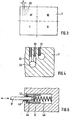
- the Fig. 1 and 2 show in a different perspective view and in a schematic manner the basic structure of a micro-machining machine 1 with a three-axis system (x, y, z) for the precision engraving of intaglio prints original.
- a rectilinear groove 3 is incorporated in the machine bed 2 .
- the orientation of this groove 3 corresponds to the x-axis.
- the cross table 4 is guided and thereby moved along the x-axis.
- the cross table 4 has a groove 5, whose Alignment of the z-axis corresponds and which is positioned exactly perpendicular to the groove 3 and thus to the x-axis.
- a holder 6 In the groove 5 of the XY stage, a holder 6 is guided, which receives the suction plate 7.
- the suction plate 7 serves as the actual workpiece holder, on which the plates to be processed are clamped by means of negative pressure. It is perpendicular to the plane formed by the x and z axes.
- On the holder 6 and the tool magazine 8 may be mounted, which serves to receive a variety of engraving tools.
- a columnar vertical support 9 On the machine bed 2, a columnar vertical support 9 is further arranged, which has a vertically extending groove 10 which extends along the y-axis.
- the processing module 11 is guided, which also includes the engraving tool.
- a guide column with squirrel cage parallel to the vertical support 9, can be used to form the y-axis. In the groove of the vertical support then the linear motor is housed. Advantage of this arrangement is the lightweight squirrel cage with optimal power distribution.
- the machine bed 2, the cross table 4, the holder 6, the suction plate 7 and the vertical support 9 are preferably made of natural hard stone, such as granite. Their surfaces are at least in the areas where other machine components are moved, executed extremely flat, preferably ground and lapped.
- the mutually perpendicular grooves 3, 5 and 10 take in the Fig. 1 and 2 not shown linear motors and the hydrostatic bearing on. These bearings and drives allow an absolute positioning accuracy in the range of ⁇ 5 ⁇ m and better with a repeat accuracy of approx. ⁇ 0.5 ⁇ m and better. In addition, such a combination avoids the so-called "stick-slip effect" and allows a free and very smooth starting and moving along the three axes.
- each axle is equipped with its own drive, the movements can be independent of each other.
- the described arrangement ensures in particular that a vertical movement of the tool along the y-axis is completely independent and uninfluenced by a horizontal movement of the workpiece in the xz-plane.
- damping elements such as air spring elements 12.
- the suction plate 7 is shown in plan view.
- a surface of the suction plate 7 is provided at a distance a, which may be for example about 10 mm, with suction openings 20, through which a workpiece is fixed on the plate surface.
- the suction openings extend over the entire surface, but are shown in the drawing only in the upper left corner of the suction plate 7.
- the suction plate 7 is preferably dimensioned such that the clamping surface covered by the suction openings 20 has a dimension of 500 ⁇ 600 mm and thereby also allows the processing of relatively large printing plate original.
- the clamping surface is preferably divided into individual quadrants, which in Fig. 3 are denoted by I to IV. The individual quadrants can have a different size and they are individually and independently controllable.
- the division into the individual quadrants is preferably carried out such that in a quadrant, for example I, small plates with a standard size of 250 x 250 mm can be clamped without additional cover.
- Fig. 4 a section of a cross section through the suction plate 7 is shown.
- the suction openings 20 are connected via bores 22 with vacuum channels 23, which may extend in line or in columns through the suction plate 7.
- the vacuum channels 23 are preferably arranged offset, so that they extend in different depths.
- the suction openings 20 are therefore made as small as possible and, for example, have a diameter of about 1 mm.
- the clamping surface with the vacuum channels 23 is first connected by holes 22 which have a larger diameter and thus are easier to manufacture.
- holes 22 Preferably, at least two rows of holes 22 are connected to a vacuum channel 23. This avoids that the suction plate is mechanically weakened by too many channels 23 too much.
- the outlet openings of the holes 22 on the clamping surface are provided with additional pressed or glued sleeves, preferably made of brass, which reduce the effective outlet opening.
- the inner sleeve diameter forms the actual suction opening 20.
- the clamping surface of the suction plate 7 can be lapped after the introduction of the sleeves 21, whereby an exact flatness of the clamping surface is ensured even in this preferred embodiment.
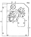
- Fig. 5 shows a plan view of the processing module 11, in the representation of Fig. 2 in the direction of the z-axis.
- the processing module 11 includes, inter alia, the machining spindle 30, on which a collet with the engraving tool 31 is located.
- spray nozzles 32 for supplying a cooling and / or lubricating medium, which are aligned with the tip of the engraving tool 31, and a suction device 33 to dissipate spray of the coolant or lubricant and chips.
- a non-contact distance sensor 34 is preferably arranged.
- Suitable distance sensors are, for example, eddy current sensors, capacitive distance sensors or light scanners. These measure the length growth, ie the axial position change of the machining spindle in the direction of the z-axis and provide the correction value S0 for the z-coordinate.
- the resolution of such distance sensors for measuring the change in length of the machining spindle is about 0.1 microns.
- the processing module 11 is equipped with observation devices 35, 36.
- a video microscope 35 is aligned via an angle mirror on the tool tip and the processing area.
- a sufficient illumination of the observed area provides as a means of illumination 37, for example, a flexible light guide.
- the image signal of the video microscope 35 is forwarded to a monitor and allows playback with a preferably 50 to 100 times the total magnification.
- another video microscope 36 can be directed in the direction of the z-axis onto the workpiece surface.
- This surveying system is preferably equipped with a further illumination means 38 and for protecting the objective with a rotatable cover.
- the cover can be rotated so that the opening 39 exposes the lens.
- the surveying system allows, for example by a connected monitor, preferably a computer with frame grabber and image processing software, the precise measurement of even the finest engraving by an approximately 400- to 600-fold total magnification.
- the entire processing module 11 is guided on the vertical support 9 in the groove 10 or on the guide column and moved by a linear motor in the direction of the y-axis on the vertical support.
- Fig. 6 is shown schematically the automatic tool change in the tool magazine 8.
- a section from a cross section through the tool magazine 8 is reproduced, by means of which the mounting and positioning of the engraving tool 31 is clarified.
- the engraving tool must be clamped into the tool holder with a predetermined, protruding length. For this it is necessary to store the tools so that the processing tip occupies a defined position. On the other hand, it must be ensured that the sensitive tool cutting edge is undamaged and therefore stored without contact.
- the engraving tool 31 can be introduced in the automated tool change through an opening 40 which is slightly larger than the tool diameter, with the processing tip in a cavity of the tool magazine 8.
- the clamping element 42 is preferably designed as a rubber O-ring.
- the sliding sleeve 44 forms a stop for the cutting-side end of the engraving tool 31 and positions the inserted tool in a defined, predetermined position. By a central bore in the sliding sleeve 44 ensures that the cutting edge is mounted without contact at the top of the engraving tool 31.
Landscapes
- Engineering & Computer Science (AREA)
- Manufacturing & Machinery (AREA)
- Manufacture Or Reproduction Of Printing Formes (AREA)
- Laminated Bodies (AREA)
- Application Of Or Painting With Fluid Materials (AREA)
- Shaping Of Tube Ends By Bending Or Straightening (AREA)
Claims (40)
- Procédé de fabrication, par gravure mécanique, de plaques d'impression en creux par gravure, l'usinage ayant lieu au moyen d'au moins trois axes libres déplaçables indépendamment les uns des autres, caractérisé en ce que les températures de composantes importantes sont continûment surveillées et le cas échéant régulées, de telle sorte qu'une stabilisation thermique suffisante couvrant la période d'usinage a lieu, et qu'une pièce y compris un porte-pièce est déplacée à l'horizontale le long d'un axe x et z par deux entraînements indépendants l'un de l'autre et qu'une coordonnée y donnée est réglée par un déplacement vertical d'un outil ou d'un module d'usinage.
- Procédé selon la revendication 1, caractérisé en ce que les déplacements le long des axes sont sont guidés sur des paliers hydrostatiques.
- Procédé selon la revendication 2, caractérisé en ce que la température des paliers hydrostatiques et/ou de préférence de leur huile hydraulique est régulée.
- Procédé selon au moins une des revendications de 1 à 3, caractérisé en ce que les déplacements et positionnements le long des axes ont lieu par l'intermédiaire de moteurs linéaires.
- Procédé selon la revendication 4, caractérisé en ce que la température des moteurs linéaires est régulée.
- Procédé selon au moins une des revendications de 1 à 5, caractérisé en ce que la plaque d'impression est tenue par une plaque de succion pendant l'usinage.
- Procédé selon la revendication 6, caractérisé en ce que la température de la plaque de succion est régulée.
- Procédé selon au moins une des revendications de 1 à 7, caractérisé en ce que l'outil de gravure est entraîné par une broche d'usinage à une vitesse de rotation de ≥ 100.000 t/min.
- Procédé selon la revendication 8, caractérisé en ce que la température de la broche d'usinage et/ou du porte-broche est régulée.
- Procédé selon au moins une des revendications de 3 à 9, caractérisé en ce que la précision de régulation pour une ou plusieurs, de préférence pour toutes des températures, est de ≤ ± 1° C.
- Procédé selon au moins une des revendications de 1 à 10, caractérisé en ce que, avant le commencement de l'usinage, la position réelle de la surface de la pièce à travailler serrée est repérée (W0).
- Procédé selon au moins une des revendications de 1 à 11, caractérisé en ce que, avant le commencement de l'usinage et le cas échéant aussi pendant ce dernier, la position réelle du tranchant de l'outil de gravure serré est repérée (Z0).
- Procédé selon la revendication 12, caractérisé en ce que la position du tranchant est repérée au moyen d'un palpeur de mesure sur coussin d'air.
- Procédé selon au moins une des revendications 8 ou 9, caractérisé en ce que, pendant l'usinage, la position axiale de la broche d'usinage est repérée (S0).
- Procédé selon la revendication 14, caractérisé en ce que la position de la broche d'usinage est mesurée au moyen d'un capteur à courants de Foucault.
- Procédé selon au moins une des revendications de 1 à 15, caractérisé en ce qu'au moins une, de préférence toutes des grandeurs suivantes sont relevées ou enregistrées pendant l'usinage de la plaque d'impression: heure, coordonnées spatiales (x,y,z), pression négative de la plaque de succion, températures des composantes régulées, température ambiante, modification axiale de position de la broche d'usinage (S0), longueur effective d'outil (Z0), position de la surface de la pièce à travailler (W0).
- Procédé selon au moins une des revendications de 1 à 16, caractérisé en ce que le processus d'usinage est contrôlé par un équipement d'observation optique.
- Dispositif de fabrication, par gravure mécanique, de plaques d'impression en creux par gravure, le dispositif comportant au moins trois axes de déplacement libres déplaçables indépendamment les uns des autres, caractérisé en ce qu'il comporte des moyens de continûment surveiller et le cas échéant réguler les températures de composantes importantes, de telle sorte qu'une stabilisation thermique suffisante couvrant la période d'usinage a lieu, et qu'une pièce y compris un porte-pièce est déplaçable à l'horizontale le long d'un axe x et z par deux entraînements indépendants l'un de l'autre et qu'une coordonnée y donnée est réglable par un déplacement vertical d'un outil ou d'un module d'usinage.
- Dispositif selon la revendication 18, caractérisé en ce que le déplacement vertical est entièrement découplé mécaniquement du déplacement horizontal.
- Dispositif selon la revendication 18 ou 19, caractérisé en ce que les axes de déplacement comportent des paliers hydrostatiques.
- Dispositif selon la revendication 20, caractérisé en ce qu'il comporte une régulation de température pour les paliers hydrostatiques et/ou de préférence pour leur huile hydraulique.
- Dispositif selon au moins une des revendications de 18 à 21, caractérisé en ce que, pour le déplacement et positionnement le long des axes, il comporte des moteurs linéaires.
- Dispositif selon la revendication 22, caractérisé en ce qu'il comporte une régulation de température pour les moteurs linéaires.
- Dispositif selon au moins une des revendications de 18 à 23, caractérisé en ce que, pour la tenue de la plaque d'impression, il comporte une plaque de succion.
- Dispositif selon la revendication 24, caractérisé en ce qu'il comporte une régulation de température pour la plaque de succion.
- Dispositif selon une des revendications 24 ou 25, caractérisé en ce que la plaque de succion comporte sur sa surface de serrage des alésages dans lesquels sont fixées des douilles, et en ce que les diamètres intérieurs des douilles constituent les orifices de succion.
- Dispositif selon une des revendications de 24 à 26, caractérisé en ce que les orifices de succion de la plaque de succion présentent un diamètre de 0,5 à 2 mm, de préférence 1 mm.
- Dispositif selon au moins une des revendications de 18 à 27, caractérisé en ce qu'il comporte une régulation de température pour la broche d'usinage.
- Dispositif selon au moins une des revendications de 18 à 28, caractérisé en ce qu'il comporte des moyens de balayage et de détection de la position de la surface de la pièce à travailler serrée.
- Dispositif selon les revendications 28 ou 29, caractérisé en ce qu'il comporte des moyens de détection de la position axiale de la broche d'usinage.
- Dispositif selon la revendication 30, caractérisé en ce qu'il comporte un capteur à courants de Foucault pour la détermination de la position.
- Dispositif selon au moins une des revendications de 18 à 31, caractérisé en ce qu'il comporte des moyens de détection de la position du tranchant de l'outil de gravure serré.
- Dispositif selon la revendication 32, caractérisé en ce que, pour la détermination de la position, il comporte un palpeur de mesure sur coussin d'air.
- Dispositif selon la revendication 33, caractérisé en ce que la force de mesure du palpeur de mesure est de ≤ 0,1 N.
- Dispositif selon au moins une des revendications de 18 à 34, caractérisé en ce qu'il comporte des moyens pour un changement automatisé d'outil.
- Dispositif selon au moins une des revendications de 18 à 35, caractérisé en ce qu'il comporte un magasin à outils qui peut accueillir une pluralité d'outils de gravure.
- Dispositif selon la revendication 36, caractérisé en ce que les tranchants des outils de gravure sont entreposés dans le magasin dans une position définie et sans se toucher.
- Dispositif selon au moins une des revendications de 18 à 37, caractérisé en ce qu'il comporte un équipement d'observation optique pour le processus d'usinage.
- Dispositif selon au moins une des revendications de 18 à 38, caractérisé en ce qu'il comporte un équipement d'observation pour le mesurage optique des gravures générées.
- Dispositif selon au moins une des revendications de 24 à 39, caractérisé en ce que la plaque de succion est en pierre naturelle, de préférence en granite.
Applications Claiming Priority (3)
| Application Number | Priority Date | Filing Date | Title |
|---|---|---|---|
| DE10260253 | 2002-12-20 | ||
| DE10260253A DE10260253A1 (de) | 2002-12-20 | 2002-12-20 | Verfahren und Vorrichtung zur Herstellung von Stichtiefdruckplatten und damit hergestellte Druckplatte |
| PCT/EP2003/014610 WO2004056568A2 (fr) | 2002-12-20 | 2003-12-19 | Procede et dispositif pour fabriquer des plaques d'impression helio et plaque d'impression ainsi fabriquee |
Publications (3)
| Publication Number | Publication Date |
|---|---|
| EP1578604A2 EP1578604A2 (fr) | 2005-09-28 |
| EP1578604B1 EP1578604B1 (fr) | 2011-03-23 |
| EP1578604B2 true EP1578604B2 (fr) | 2014-06-18 |
Family
ID=32404121
Family Applications (1)
| Application Number | Title | Priority Date | Filing Date |
|---|---|---|---|
| EP03782459.6A Expired - Lifetime EP1578604B2 (fr) | 2002-12-20 | 2003-12-19 | Procede et dispositif pour fabriquer des plaques d'impression helio |
Country Status (6)
| Country | Link |
|---|---|
| EP (1) | EP1578604B2 (fr) |
| AT (1) | ATE502775T1 (fr) |
| AU (1) | AU2003290099A1 (fr) |
| DE (2) | DE10260253A1 (fr) |
| RU (1) | RU2348533C2 (fr) |
| WO (1) | WO2004056568A2 (fr) |
Families Citing this family (5)
| Publication number | Priority date | Publication date | Assignee | Title |
|---|---|---|---|---|
| US20070227384A1 (en) * | 2006-04-03 | 2007-10-04 | Mcgaire Mark D | Imaging and punching thermal control system |
| DE102007045015A1 (de) * | 2007-09-20 | 2009-04-02 | Giesecke & Devrient Gmbh | Vorrichtung und Verfahren zur Erzeugung von Mehrnutzen-Stichtiefdruckplatten |
| RU2467859C1 (ru) * | 2011-06-29 | 2012-11-27 | Федеральное Государственное Унитарное Предприятие "Гознак" (Фгуп "Гознак") | Способ формирования объемных микроструктур рисунка гравюры в функциональном слое металлографской формы на автоматизированном гравировальном программно-аппаратном комплексе |
| RU2624717C1 (ru) * | 2016-03-11 | 2017-07-05 | Закрытое акционерное общество "Санкт-Петербургская Образцовая Типография" | Способ изготовления клише для тиснения |
| DE102021002867A1 (de) | 2021-06-02 | 2022-12-08 | Giesecke+Devrient Currency Technology Gmbh | Stichtiefdruckplatte mit verlängerter Haltbarkeitsdauer und Verfahren zu deren Herstellung |
Citations (11)
| Publication number | Priority date | Publication date | Assignee | Title |
|---|---|---|---|---|
| DE2508985A1 (de) † | 1974-03-01 | 1975-09-04 | Crosfield Electronics Ltd | Verfahren und vorrichtung zur herstellung eines tiefdruckzylinders |
| EP0595324A1 (fr) † | 1992-10-28 | 1994-05-04 | Dainippon Screen Mfg. Co., Ltd. | Calibreur automatique en temps réel pour stylet électromécanique de rotogravure |
| EP0652075A2 (fr) † | 1993-09-14 | 1995-05-10 | Eduard Huber Management Ag | Dispositif d'usinage de pièces |
| WO1996023201A1 (fr) † | 1995-01-23 | 1996-08-01 | Ohio Electronic Engravers, Inc. | Procede et appareil de gravure en creux |
| WO1997027026A1 (fr) † | 1996-01-23 | 1997-07-31 | Renault-Automation | Structure logique d'une machine-outil d'usinage a grande vitesse du type porte-broche |
| WO1997048555A1 (fr) † | 1996-06-17 | 1997-12-24 | Giesecke & Devrient Gmbh | Procede de production de plaques a gaufrer |
| US5731881A (en) † | 1994-11-04 | 1998-03-24 | Ohio Electronic Engravers, Inc. | Engraving method and apparatus using cooled magnetostrictive actuator |
| WO1999007554A1 (fr) † | 1997-08-08 | 1999-02-18 | Heidelberger Druckmaschinen Ag | Procede de positionnement d'organes de gravure |
| WO1999030482A1 (fr) † | 1997-12-09 | 1999-06-17 | Heidelberger Druckmaschinen Aktiengesellschaft | Procede de fonctionnement d'un organe de gravure |
| DE10101134A1 (de) † | 2001-01-12 | 2002-07-18 | Heidelberger Druckmasch Ag | Kühlungseinrichtung zur Kühlung eines Graviersystems |
| US20020135811A1 (en) † | 1993-02-25 | 2002-09-26 | Flannery David L. | Error detection apparatus and method for use with engravers |
Family Cites Families (8)
| Publication number | Priority date | Publication date | Assignee | Title |
|---|---|---|---|---|
| DE4212175A1 (de) * | 1992-04-10 | 1993-10-14 | Emag Masch Vertriebs Serv Gmbh | Aus Baugruppen zusammengesetztes Bearbeitungszentrum |
| RU2076046C1 (ru) * | 1992-06-30 | 1997-03-27 | Виктор Николаевич Бондарев | Система для переноса изображения на поверхность камня и графическое мозаичное устройство для выполнения изображения |
| US5424845A (en) * | 1993-02-25 | 1995-06-13 | Ohio Electronic Engravers, Inc. | Apparatus and method for engraving a gravure printing cylinder |
| US5867280A (en) * | 1993-02-25 | 1999-02-02 | Ohio Electronic Engravers, Inc. | Engraver with automatic tool changer |
| RU2077700C1 (ru) * | 1993-09-20 | 1997-04-20 | Эдуард Семенович Костин | Способ вихретокового определения положения объекта |
| EP0741008A3 (fr) * | 1995-05-02 | 1998-05-13 | MDC Max Dätwyler Bleienbach AG | Appareil pour graver des cylindres d'impression |
| DE10044403A1 (de) * | 2000-09-08 | 2002-03-21 | Giesecke & Devrient Gmbh | Datenträger mit Stichtiefdruckbild und Verfahren zur Umsetzung von Bildmotiven in Linienstrukturen sowie in eine Stichtiefdruckplatte |
| AU2002244993A1 (en) * | 2001-12-10 | 2003-06-23 | Yakov Mikhailovich Ashkinazy | Method for producing a pattern in the functional layer of an article |
-
2002
- 2002-12-20 DE DE10260253A patent/DE10260253A1/de not_active Withdrawn
-
2003
- 2003-12-19 WO PCT/EP2003/014610 patent/WO2004056568A2/fr not_active Ceased
- 2003-12-19 AT AT03782459T patent/ATE502775T1/de active
- 2003-12-19 EP EP03782459.6A patent/EP1578604B2/fr not_active Expired - Lifetime
- 2003-12-19 AU AU2003290099A patent/AU2003290099A1/en not_active Abandoned
- 2003-12-19 DE DE50313570T patent/DE50313570D1/de not_active Expired - Lifetime
- 2003-12-19 RU RU2005122907/11A patent/RU2348533C2/ru not_active IP Right Cessation
Patent Citations (11)
| Publication number | Priority date | Publication date | Assignee | Title |
|---|---|---|---|---|
| DE2508985A1 (de) † | 1974-03-01 | 1975-09-04 | Crosfield Electronics Ltd | Verfahren und vorrichtung zur herstellung eines tiefdruckzylinders |
| EP0595324A1 (fr) † | 1992-10-28 | 1994-05-04 | Dainippon Screen Mfg. Co., Ltd. | Calibreur automatique en temps réel pour stylet électromécanique de rotogravure |
| US20020135811A1 (en) † | 1993-02-25 | 2002-09-26 | Flannery David L. | Error detection apparatus and method for use with engravers |
| EP0652075A2 (fr) † | 1993-09-14 | 1995-05-10 | Eduard Huber Management Ag | Dispositif d'usinage de pièces |
| US5731881A (en) † | 1994-11-04 | 1998-03-24 | Ohio Electronic Engravers, Inc. | Engraving method and apparatus using cooled magnetostrictive actuator |
| WO1996023201A1 (fr) † | 1995-01-23 | 1996-08-01 | Ohio Electronic Engravers, Inc. | Procede et appareil de gravure en creux |
| WO1997027026A1 (fr) † | 1996-01-23 | 1997-07-31 | Renault-Automation | Structure logique d'une machine-outil d'usinage a grande vitesse du type porte-broche |
| WO1997048555A1 (fr) † | 1996-06-17 | 1997-12-24 | Giesecke & Devrient Gmbh | Procede de production de plaques a gaufrer |
| WO1999007554A1 (fr) † | 1997-08-08 | 1999-02-18 | Heidelberger Druckmaschinen Ag | Procede de positionnement d'organes de gravure |
| WO1999030482A1 (fr) † | 1997-12-09 | 1999-06-17 | Heidelberger Druckmaschinen Aktiengesellschaft | Procede de fonctionnement d'un organe de gravure |
| DE10101134A1 (de) † | 2001-01-12 | 2002-07-18 | Heidelberger Druckmasch Ag | Kühlungseinrichtung zur Kühlung eines Graviersystems |
Also Published As
| Publication number | Publication date |
|---|---|
| ATE502775T1 (de) | 2011-04-15 |
| WO2004056568A3 (fr) | 2005-01-13 |
| RU2005122907A (ru) | 2007-01-27 |
| EP1578604B1 (fr) | 2011-03-23 |
| RU2348533C2 (ru) | 2009-03-10 |
| AU2003290099A1 (en) | 2004-07-14 |
| AU2003290099A8 (en) | 2004-07-14 |
| EP1578604A2 (fr) | 2005-09-28 |
| DE10260253A1 (de) | 2004-07-01 |
| WO2004056568A2 (fr) | 2004-07-08 |
| DE50313570D1 (de) | 2011-05-05 |
Similar Documents
| Publication | Publication Date | Title |
|---|---|---|
| EP2039529B1 (fr) | Dispositif et procédé destinés à la production de plaques d'impression hélio multi-usage | |
| EP1864753B1 (fr) | Machine d'usinage de pièces optiques, en particulier de lentilles de lunettes en plastique | |
| EP1684935B1 (fr) | Machine et procede d'usinage laser | |
| DE19745280A1 (de) | Verfahren zur Fein- und Mikrobearbeitung von Werkstücken mittels Laserstrahlen und Vorrichtung zur Durchführung des Verfahrens | |
| DE9007812U1 (de) | Mehrspindelmaschine zum Bohren, Fräsen o.dgl. | |
| EP0578018A1 (fr) | Méthode et appareil pour la finition de surfaces de coupe d'une pièce d'usinage produite par le procédé d'électro-érosion à fil | |
| DE112021004058B4 (de) | Bearbeitungsvorrichtung, Bearbeitungssystem und Verfahren zur Herstellung von bearbeiteten Werkstücken | |
| EP1764185B1 (fr) | Dispositif et méthode pour la production de micro-structures | |
| EP1578604B2 (fr) | Procede et dispositif pour fabriquer des plaques d'impression helio | |
| DE102004020990B4 (de) | Vorrichtung und Verfahren zur Erzeugung von Mikrostrukturen | |
| DE102009024752B4 (de) | Verfahren zum Vermessen und/oder Kalibrieren einer numerisch gesteuerten Werkzeugmaschine | |
| DE19734411A1 (de) | Verfahren zum Positionieren von Gravierorganen | |
| DE102018116697B4 (de) | Verfahren zum Bearbeiten einer Oberfläche eines Schmuckstücks und diesbezügliche Graviermaschine | |
| EP2923836B1 (fr) | Procédé de production d'un pochoir pour l'impression technique | |
| DE19855962C5 (de) | Verfahren zur Herstellung eines Zwischenmodells in Negativform | |
| DE102020005171B4 (de) | Hochpräzisions-Werkzeugmaschine, Verfahren zur Erzeugung einer glatten Oberfläche mit der Hochpräzisions-Werkzeugmaschine sowie Computerprogrammprodukt hierfür | |
| JP2022058930A (ja) | 微細加工装置、微細加工ユニット、制御装置、原盤の製造方法、及び原盤用基材の微細加工方法 | |
| DE19949019C2 (de) | Messgerät und Verfahren zum Vermessen von Strukturen auf Substraten verschiedener Dicke | |
| JP7023624B2 (ja) | 微細加工装置、制御装置、原盤の製造方法、及び原盤用基材の微細加工方法 | |
| DE19805735C2 (de) | Vorrichtung und Verfahren zur spanenden Bearbeitung von Werkstückoberflächen | |
| DE102005019372B3 (de) | Vorrichtung zum Markieren von Werkstück- oder Werkstoffproben | |
| DE102005043209A1 (de) | Verfahren und Vorrichtung zur spanenden Bearbeitung von Werkstücken aus Glas oder Glaskeramik | |
| DE3935695A1 (de) | Verfahren und vorrichtung zur herstellung von elektrodeneinheiten zum senkerodieren |
Legal Events
| Date | Code | Title | Description |
|---|---|---|---|
| PUAI | Public reference made under article 153(3) epc to a published international application that has entered the european phase |
Free format text: ORIGINAL CODE: 0009012 |
|
| 17P | Request for examination filed |
Effective date: 20050720 |
|
| AK | Designated contracting states |
Kind code of ref document: A2 Designated state(s): AT BE BG CH CY CZ DE DK EE ES FI FR GB GR HU IE IT LI LU MC NL PT RO SE SI SK TR |
|
| AX | Request for extension of the european patent |
Extension state: AL LT LV MK |
|
| DAX | Request for extension of the european patent (deleted) | ||
| RIN1 | Information on inventor provided before grant (corrected) |
Inventor name: ADAMCZYK, ROGER Inventor name: MAYER, KARLHEINZ Inventor name: WIDEMANN, RICHARD |
|
| 17Q | First examination report despatched |
Effective date: 20100503 |
|
| GRAP | Despatch of communication of intention to grant a patent |
Free format text: ORIGINAL CODE: EPIDOSNIGR1 |
|
| RTI1 | Title (correction) |
Free format text: METHOD AND DEVICE FOR PRODUCING INTAGLIO PRINTING PLATES |
|
| GRAS | Grant fee paid |
Free format text: ORIGINAL CODE: EPIDOSNIGR3 |
|
| GRAA | (expected) grant |
Free format text: ORIGINAL CODE: 0009210 |
|
| AK | Designated contracting states |
Kind code of ref document: B1 Designated state(s): AT BE BG CH CY CZ DE DK EE ES FI FR GB GR HU IE IT LI LU MC NL PT RO SE SI SK TR |
|
| REG | Reference to a national code |
Ref country code: GB Ref legal event code: FG4D Free format text: NOT ENGLISH |
|
| REG | Reference to a national code |
Ref country code: CH Ref legal event code: EP |
|
| REG | Reference to a national code |
Ref country code: IE Ref legal event code: FG4D |
|
| REG | Reference to a national code |
Ref country code: CH Ref legal event code: NV Representative=s name: R. A. EGLI & CO. PATENTANWAELTE |
|
| REG | Reference to a national code |
Ref country code: NL Ref legal event code: T3 |
|
| REF | Corresponds to: |
Ref document number: 50313570 Country of ref document: DE Date of ref document: 20110505 Kind code of ref document: P |
|
| REG | Reference to a national code |
Ref country code: DE Ref legal event code: R096 Ref document number: 50313570 Country of ref document: DE Effective date: 20110505 |
|
| PG25 | Lapsed in a contracting state [announced via postgrant information from national office to epo] |
Ref country code: SE Free format text: LAPSE BECAUSE OF FAILURE TO SUBMIT A TRANSLATION OF THE DESCRIPTION OR TO PAY THE FEE WITHIN THE PRESCRIBED TIME-LIMIT Effective date: 20110323 Ref country code: GR Free format text: LAPSE BECAUSE OF FAILURE TO SUBMIT A TRANSLATION OF THE DESCRIPTION OR TO PAY THE FEE WITHIN THE PRESCRIBED TIME-LIMIT Effective date: 20110624 |
|
| PG25 | Lapsed in a contracting state [announced via postgrant information from national office to epo] |
Ref country code: SI Free format text: LAPSE BECAUSE OF FAILURE TO SUBMIT A TRANSLATION OF THE DESCRIPTION OR TO PAY THE FEE WITHIN THE PRESCRIBED TIME-LIMIT Effective date: 20110323 Ref country code: FI Free format text: LAPSE BECAUSE OF FAILURE TO SUBMIT A TRANSLATION OF THE DESCRIPTION OR TO PAY THE FEE WITHIN THE PRESCRIBED TIME-LIMIT Effective date: 20110323 Ref country code: CY Free format text: LAPSE BECAUSE OF FAILURE TO SUBMIT A TRANSLATION OF THE DESCRIPTION OR TO PAY THE FEE WITHIN THE PRESCRIBED TIME-LIMIT Effective date: 20110323 Ref country code: BG Free format text: LAPSE BECAUSE OF FAILURE TO SUBMIT A TRANSLATION OF THE DESCRIPTION OR TO PAY THE FEE WITHIN THE PRESCRIBED TIME-LIMIT Effective date: 20110623 |
|
| REG | Reference to a national code |
Ref country code: IE Ref legal event code: FD4D |
|
| PG25 | Lapsed in a contracting state [announced via postgrant information from national office to epo] |
Ref country code: PT Free format text: LAPSE BECAUSE OF FAILURE TO SUBMIT A TRANSLATION OF THE DESCRIPTION OR TO PAY THE FEE WITHIN THE PRESCRIBED TIME-LIMIT Effective date: 20110725 Ref country code: EE Free format text: LAPSE BECAUSE OF FAILURE TO SUBMIT A TRANSLATION OF THE DESCRIPTION OR TO PAY THE FEE WITHIN THE PRESCRIBED TIME-LIMIT Effective date: 20110323 |
|
| PG25 | Lapsed in a contracting state [announced via postgrant information from national office to epo] |
Ref country code: SK Free format text: LAPSE BECAUSE OF FAILURE TO SUBMIT A TRANSLATION OF THE DESCRIPTION OR TO PAY THE FEE WITHIN THE PRESCRIBED TIME-LIMIT Effective date: 20110323 Ref country code: CZ Free format text: LAPSE BECAUSE OF FAILURE TO SUBMIT A TRANSLATION OF THE DESCRIPTION OR TO PAY THE FEE WITHIN THE PRESCRIBED TIME-LIMIT Effective date: 20110323 Ref country code: ES Free format text: LAPSE BECAUSE OF FAILURE TO SUBMIT A TRANSLATION OF THE DESCRIPTION OR TO PAY THE FEE WITHIN THE PRESCRIBED TIME-LIMIT Effective date: 20110704 Ref country code: RO Free format text: LAPSE BECAUSE OF FAILURE TO SUBMIT A TRANSLATION OF THE DESCRIPTION OR TO PAY THE FEE WITHIN THE PRESCRIBED TIME-LIMIT Effective date: 20110323 |
|
| PLBI | Opposition filed |
Free format text: ORIGINAL CODE: 0009260 |
|
| PLAX | Notice of opposition and request to file observation + time limit sent |
Free format text: ORIGINAL CODE: EPIDOSNOBS2 |
|
| PG25 | Lapsed in a contracting state [announced via postgrant information from national office to epo] |
Ref country code: IE Free format text: LAPSE BECAUSE OF FAILURE TO SUBMIT A TRANSLATION OF THE DESCRIPTION OR TO PAY THE FEE WITHIN THE PRESCRIBED TIME-LIMIT Effective date: 20110323 |
|
| 26 | Opposition filed |
Opponent name: KBA-NOTASYS SA Effective date: 20111222 |
|
| REG | Reference to a national code |
Ref country code: DE Ref legal event code: R026 Ref document number: 50313570 Country of ref document: DE Effective date: 20111222 |
|
| PLBB | Reply of patent proprietor to notice(s) of opposition received |
Free format text: ORIGINAL CODE: EPIDOSNOBS3 |
|
| REG | Reference to a national code |
Ref country code: CH Ref legal event code: NV Representative=s name: PATENTANWAELTE SCHAAD, BALASS, MENZL & PARTNER AG |
|
| PG25 | Lapsed in a contracting state [announced via postgrant information from national office to epo] |
Ref country code: IT Free format text: LAPSE BECAUSE OF FAILURE TO SUBMIT A TRANSLATION OF THE DESCRIPTION OR TO PAY THE FEE WITHIN THE PRESCRIBED TIME-LIMIT Effective date: 20110323 |
|
| BERE | Be: lapsed |
Owner name: GIESECKE & DEVRIENT G.M.B.H. Effective date: 20111231 |
|
| REG | Reference to a national code |
Ref country code: NL Ref legal event code: V1 Effective date: 20120701 |
|
| PG25 | Lapsed in a contracting state [announced via postgrant information from national office to epo] |
Ref country code: MC Free format text: LAPSE BECAUSE OF NON-PAYMENT OF DUE FEES Effective date: 20111231 |
|
| REG | Reference to a national code |
Ref country code: CH Ref legal event code: PL Ref country code: CH Ref legal event code: AEN Free format text: REAKTIVIERUNG NACH IRRTUEMLICHER LOESCHUNG |
|
| GBPC | Gb: european patent ceased through non-payment of renewal fee |
Effective date: 20111219 |
|
| REG | Reference to a national code |
Ref country code: FR Ref legal event code: ST Effective date: 20120831 |
|
| PG25 | Lapsed in a contracting state [announced via postgrant information from national office to epo] |
Ref country code: GB Free format text: LAPSE BECAUSE OF NON-PAYMENT OF DUE FEES Effective date: 20111219 Ref country code: BE Free format text: LAPSE BECAUSE OF NON-PAYMENT OF DUE FEES Effective date: 20111231 |
|
| PG25 | Lapsed in a contracting state [announced via postgrant information from national office to epo] |
Ref country code: NL Free format text: LAPSE BECAUSE OF NON-PAYMENT OF DUE FEES Effective date: 20120701 |
|
| REG | Reference to a national code |
Ref country code: AT Ref legal event code: MM01 Ref document number: 502775 Country of ref document: AT Kind code of ref document: T Effective date: 20111219 |
|
| PG25 | Lapsed in a contracting state [announced via postgrant information from national office to epo] |
Ref country code: FR Free format text: LAPSE BECAUSE OF NON-PAYMENT OF DUE FEES Effective date: 20120102 |
|
| PG25 | Lapsed in a contracting state [announced via postgrant information from national office to epo] |
Ref country code: CH Free format text: LAPSE BECAUSE OF NON-PAYMENT OF DUE FEES Effective date: 20111231 Ref country code: LI Free format text: LAPSE BECAUSE OF NON-PAYMENT OF DUE FEES Effective date: 20111231 Ref country code: LU Free format text: LAPSE BECAUSE OF NON-PAYMENT OF DUE FEES Effective date: 20111219 |
|
| PG25 | Lapsed in a contracting state [announced via postgrant information from national office to epo] |
Ref country code: AT Free format text: LAPSE BECAUSE OF NON-PAYMENT OF DUE FEES Effective date: 20111219 |
|
| PG25 | Lapsed in a contracting state [announced via postgrant information from national office to epo] |
Ref country code: TR Free format text: LAPSE BECAUSE OF FAILURE TO SUBMIT A TRANSLATION OF THE DESCRIPTION OR TO PAY THE FEE WITHIN THE PRESCRIBED TIME-LIMIT Effective date: 20110323 |
|
| PG25 | Lapsed in a contracting state [announced via postgrant information from national office to epo] |
Ref country code: HU Free format text: LAPSE BECAUSE OF FAILURE TO SUBMIT A TRANSLATION OF THE DESCRIPTION OR TO PAY THE FEE WITHIN THE PRESCRIBED TIME-LIMIT Effective date: 20110323 |
|
| PUAH | Patent maintained in amended form |
Free format text: ORIGINAL CODE: 0009272 |
|
| STAA | Information on the status of an ep patent application or granted ep patent |
Free format text: STATUS: PATENT MAINTAINED AS AMENDED |
|
| REG | Reference to a national code |
Ref country code: DE Ref legal event code: R082 Ref document number: 50313570 Country of ref document: DE |
|
| 27A | Patent maintained in amended form |
Effective date: 20140618 |
|
| AK | Designated contracting states |
Kind code of ref document: B2 Designated state(s): AT BE BG CH CY CZ DE DK EE ES FI FR GB GR HU IE IT LI LU MC NL PT RO SE SI SK TR |
|
| REG | Reference to a national code |
Ref country code: DE Ref legal event code: R102 Ref document number: 50313570 Country of ref document: DE Effective date: 20140618 |
|
| PGFP | Annual fee paid to national office [announced via postgrant information from national office to epo] |
Ref country code: DE Payment date: 20141231 Year of fee payment: 12 |
|
| REG | Reference to a national code |
Ref country code: DE Ref legal event code: R119 Ref document number: 50313570 Country of ref document: DE |
|
| PG25 | Lapsed in a contracting state [announced via postgrant information from national office to epo] |
Ref country code: DE Free format text: LAPSE BECAUSE OF NON-PAYMENT OF DUE FEES Effective date: 20160701 |