EP1578604B2 - Method and device for producing intaglio printing plates - Google Patents
Method and device for producing intaglio printing plates Download PDFInfo
- Publication number
- EP1578604B2 EP1578604B2 EP03782459.6A EP03782459A EP1578604B2 EP 1578604 B2 EP1578604 B2 EP 1578604B2 EP 03782459 A EP03782459 A EP 03782459A EP 1578604 B2 EP1578604 B2 EP 1578604B2
- Authority
- EP
- European Patent Office
- Prior art keywords
- machining
- tool
- engraving
- workpiece
- printing
- Prior art date
- Legal status (The legal status is an assumption and is not a legal conclusion. Google has not performed a legal analysis and makes no representation as to the accuracy of the status listed.)
- Expired - Lifetime
Links
Images

Classifications
-
- B—PERFORMING OPERATIONS; TRANSPORTING
- B41—PRINTING; LINING MACHINES; TYPEWRITERS; STAMPS
- B41C—PROCESSES FOR THE MANUFACTURE OR REPRODUCTION OF PRINTING SURFACES
- B41C1/00—Forme preparation
- B41C1/02—Engraving; Heads therefor
Definitions
- the invention relates to a method for producing intaglio printing plates and a device for producing these plates.
- Under pressure plates according to the invention are not only printing plates, in particular intaglio printing plates for the ink-carrying printing, but also for the blind printing, so-called embossing plates to understand.
- printing forms used for gravure printing are produced by means of chemical or mechanical processes.
- cup-like depressions typical for screen deep printing are produced by a photochemical etching process in which acid acts on the printing plate surface.
- the grid webs between the wells are relatively sensitive to pressure, so that they are affected during the printing process or even destroyed and so a high circulation strength is not guaranteed (Bruckmann's Handbook of Printing Technology, S 171ff).
- image motifs are traditionally engraved in a time-consuming manual work using a stylus in a metal plate, such as steel or copper.
- a stylus in a metal plate, such as steel or copper.
- the grayscale of the image motif is displayed with lines of different widths and / or depths and a different number of lines per area.
- the engraving of a printing cylinder can also be done by machine.
- intaglio printing is characterized in particular by the fact that a continuous line print pattern, which can be felt with the application of color, is transferred to the print substrate, which is particularly distinguished by its filigree lines.
- the WO 97/48555 proposes therefore a method for producing a steel gravure printing plate in which the plate is engraved by machine and the image is not implemented in a cell grid, but are determined from a line drawing surface elements engraved. A tool is moved along three free axes.
- a device for machining workpieces describes the EP 0 652 075 A ,
- the device has a tool post made of natural stone designed as a portal, which is mounted on a work table of the same material by means of an air bearing device in order to move the tool stand, wherein the bearing device is arranged in the portal.
- a vacuum chuck is formed in the work table to hold the workpiece to be machined on the surface of the work table.
- the device can be processed with high removal rates material with three-dimensional contours or free-form surfaces or thin-walled parts with high accuracy and high feeds.
- WO 99/30482 A1 a method for engraving printing cylinders by means of an engraving element in the form of an engraving stylus in an electronic engraving machine is known in which engraved engraving engraved a grave engraved cups in a rotating impression cylinder.
- the operating temperature in the engraving element is measured at at least one measuring location.
- the electrical control of the engraving element is corrected and / or the temperature of at least one component of the engraving element and / or the air flowing around the engraving element is changed.
- Out DE 2508985 A1 is a method for producing a gravure cylinder is known in which a cylinder is provided with a surface of a hard material initially with wells uniform depth, which are then filled with a softer material, preferably plastic. The resulting excess softer material protruding over the wells in the hard material is removed, the surface of the hard material serving as a reference plane.
- Out WO 99/07554 A1 is a method for positioning of engraving in an electronic engraving machine for engraving gravure cylinders is known in which at least two adjacent Engierstrlinde engraved with one engraving each. Axial reference positions are specified for the engraving elements, on which an electronic position-measuring device is successively positioned.
- the position measuring device determines the axial deviation of the engraving stylus tip of the corresponding engraving element or the deviation of at least one cup, which has been probed with the corresponding engraving element, from the reference position. Subsequently, the engraving organs are shifted by the detected deviations and thus positioned exactly on the reference positions.
- the object of the invention is to provide a method for the production of printing plates available, wherein the printing or embossing contours of the plate have an accuracy of preferably about at least 1 micron.
- Another object of the invention is to provide an apparatus for carrying out the method.
- intaglio printing plates in the mechanical engraving of intaglio printing plates, all essential parameters influencing the engraving process are monitored and optionally regulated, so that they are sufficiently stabilized over the entire processing period of a printing plate.
- intaglio printing plates can be produced whose contours have an accuracy of preferably approximately at least 1 ⁇ m.
- a device with at least three free axes is used, which operate independently of one another and are preferably each driven by linear motors and moved on hydrostatic bearings.
- a workpiece is moved together with a workpiece holder by two independent drives in the horizontal along an x- and z-axis and set a predetermined y-coordinate by a vertical movement of a tool or a processing module.
- Several components of the device are thermally stabilized. In particular for determining the actual position of the tool cutting edge relative to the workpiece surface, a plurality of correction values can be determined and taken into account in the control of the insertion depth of the engraving tool.
- hydrostatic bearings for the components to be moved, which allow a high rigidity with very low-friction movement. While sliding or rolling bearings at start, i. At the beginning of the movement or when reversing the direction of movement caused by adhesion forces, uncontrolled jerky movements (so-called stick-slip effect), allow hydrostatic bearings a very smooth and smooth movement and thus a more accurate positioning. Hydrostatic bearings can be integrated, for example, in longitudinal grooves, which correspond to the directions of movement or axes of the processing device. Individual components of the processing device can thereby be stored, moved and positioned floating on an oil film.
- the temperatures of important components are monitored according to the invention. Uncontrolled temperature fluctuations or changes can have a variety of causes and also occur only locally on individual components. Due to the coefficients of thermal expansion of the materials involved, they can lead to uncontrolled dimensional changes and thereby adversely affect the machining result of the machine where the highest precision is required.
- the temperatures of important components are monitored during the machining process of a workpiece. Particularly critical temperatures are actively controlled by means of suitable thermostats and tempering to a predetermined target temperature. This applies in particular to the temperature of the machining spindle and its holder, the linear motors and their cooling water, the workpiece holder (vacuum plate) and the bearings of the three axes of movement and the oil of the hydrostatic bearings.
- the actual temperature can be measured at intervals of 1 s to 5 min, typically measuring intervals of about 10 s.
- the control accuracy is preferably ⁇ ⁇ 1 °, more preferably ⁇ ⁇ 0.5 °, most preferably ⁇ ⁇ 0.1 ° C.
- a high control accuracy and constancy of the controlled temperatures is required because it has been shown that given the dimensions and materials already a temperature fluctuation of about 5 ° C on an axis can lead to a deviation of up to 6 microns.
- these critical parameters are recorded and logged during processing of a printing plate. This makes it possible to understand the influence of fluctuations or disturbances in individual parameters on the machined workpiece. By logging the x, y coordinates during the engraving process, it is also possible to associate errors detected in the engraving of a printing or embossing plate at a later time with the deviation of a recorded parameter, for example a temperature fluctuation.
- storage and visual representation of the time course of the logged parameters is preferably a separate electronic data processing, such as a personal computer (PC) used.
- PC personal computer
- the long-term logging of critical parameters has the advantage that, if errors occur, the causes can also be determined subsequently. This is particularly advantageous in printing and embossing plates, which are particularly large and / or have a particularly complex or filigree pattern, since their processing times can be several days.
- Highest precision and reproducibility in the printing plate processing requires an independent and possibly mechanically decoupled movement along the individual spatial axes.
- a separate, independently operating drive is used for each of the three spatial axes.
- the processing device is designed so that the workpiece together with the workpiece holder can be moved by two independent drives in the horizontal along the x- and z-axis.
- a predetermined y-coordinate is set by a vertical movement of the tool or the machining module. The movement of the tool along the y-axis takes place along a separate, columnar support and is thereby mechanically completely decoupled from the movement along the x and z coordinates.
- the drives are of particular importance for movement along the individual axes. Since the resulting on the individual axes errors in the workpiece machining add, according to the invention on conventionally operating mechanical drives, which operate for example with gear drives and threaded rods dispensed. A particularly high positioning accuracy is achieved by the use of linear motor drives, since they have no mechanical play.
- a separate drive is used for each axis.
- a linear motor as a drive for movements along the y-axis, whereby the vertical positioning of the tool takes place.
- the fixation of the workpieces to be processed, such as printing plates, preferably takes place via a flat suction plate, which frictionally fixes the workpiece by means of a negative pressure acting on one side.
- the suction plate is traversed in its interior by largely parallel, for example vertically arranged channels.
- the channels are connected to a device for generating a negative pressure, for example a vacuum pump.
- Openings are arranged along the channels connecting the vacuum channels to the workpiece side surface of the suction plate.
- These suction openings are preferably arranged so that they are evenly spaced from each other.
- the distance between two adjacent intake ports may be, for example, about 1 cm.
- the suction openings have a diameter which is preferably not substantially greater than about 1 mm. In order not to adversely affect the stability and rigidity of the suction plate by too many or too closely adjacent channels, preferably at least two adjacent rows of suction openings are connected to the same channel.
- Suction plates known from the prior art are made of metal, predominantly aluminum plates. Due to the high thermal conductivity and the relatively large thermal expansion coefficients of metals, and in particular of aluminum, thereby large temperature fluctuations and changes in length can be introduced into the workpiece, resulting in non-negligible errors in a precision engraving.
- a suction plate is used, which is made of natural stone, preferably granite. Natural stone slabs, and in particular granite slabs, also have a vibration-damping effect and are characterized by particularly high mechanical rigidity. Their surface can be made extremely flat and they have a high heat capacity with low thermal conductivity. This also leads to lower temperature fluctuations on the workpiece.
- the holes can also be made larger and subsequently with an example. be glued or pressed sleeve provided. The easier to handle sleeves are then along their longitudinal axis with a channel of the desired diameter (for example, 1 mm) to be provided.
- the workpieces to be processed deviate from their ideal target geometry and exhibit variations in the thickness and the flatness of their surface.
- these irregularities and deviations of the workpiece surface are preferably taken into account in the calculation of the immersion depth of the engraving tool. Theoretically, any unevenness in the workpiece can be compensated for. Deviations of up to ⁇ 100 ⁇ m are to be expected in practice, with values around ⁇ 60 ⁇ m being common. For this purpose, the three-dimensional height profile of the workpiece surface is determined before the engraving begins.
- the coordinates of individual support points are known, while the position of the workpiece surface can be interpolated arithmetically for points lying between the measuring points.
- the number of measuring points can be around 40,000.
- common printing plate formats usually 20,000 measuring points are determined.
- the surface scan of the workpiece thus provides a correction value W0 for the calculation and control of the insertion depth of the engraving tool. This movement of the tool relative to the workpiece takes place in the direction of the z-axis.
- a further correction value for the z-coordinate is obtained, even if the axial position change of the machining spindle is taken into account.
- the axial position changes of the spindle occurring during operation have two main causes. On the one hand, the position of the spindle changes in its axial bearing as a function of the rotational speed of the spindle drive and, on the other hand, heating of the spindle by the heat loss of the drive leads to an axial length expansion.
- the engraving tool z. B. attached with a collet On the machining spindle, the engraving tool z. B. attached with a collet. The two mentioned influences lead to an axial position change of the machining spindle at the front, tool-side end, which change the immersion depth (i.e., the actual z-coordinate) of the tip of the engraving tool.
- the axial position of the spindle in the z-direction during operation is continuously determined at a point close to the tool as possible, these influences can be eliminated by a corresponding correction value S0 for the z-coordinate. This can avoid long and annoying warm-up phases to achieve constant conditions.
- the position measurement is preferably carried out directly on the tool tip.
- the tip of the engraving tool is moved against a measuring system and recorded the position of the tool tip in the z-direction with the highest precision.
- a measuring system for the measurement are preferably mechanical measuring systems in question, which have a flat stop surface against which the tool tip is driven.
- the measuring force should not exceed 0.1 N and is preferably ⁇ 0.01 N. Such values are achieved, for example, by air-borne measuring probes.
- Non-contact optical measuring systems in which the position of the tool tip is detected and measured by means of suitable optics and means and methods of image processing can also be used.
- engraving tools are preferably used with different cutting geometry.
- a suitable tool is selected for the engraving of the relevant area of the plate.
- preference is given to using tools whose cutting edges have a small tip radius and a small tip angle (for example 5 to 50 ⁇ m and 20 to 120 °).
- tools with a larger tip radius and a larger tip angle are preferred.
- the machine is preferably equipped with a magazine for holding a plurality of tools and an apparatus for an automatic tool change.
- the tool magazine in conjunction with the changing device not only allows the quick and easy replacement of tools of different geometry, but also the replacement of damaged or worn tools.
- a magazine for example, a dozen different and / or the same engraving stylus can be kept ready.
- the tool magazine is preferably rigid and immovable. That when a tool change the magazine is not moved, so that the new tool is brought to the tool holder, but the tool holder, such as a collet moves to the tool in the intended change position.
- the tools are to be guided during the change and fixed in the magazine so that the cutting edges are not touched.
- the engraving tools are preferably made of wear-resistant material.
- wear-resistant material for this example, sintered hard metals in question, but also ceramic cutting tools or those made of high-alloy tool steels with a diamond-coated cutting edge or a cutting edge, which was made entirely of diamond material.
- the hardness of the engraving tool is about 10 to 20 times higher than the hardness of the machined workpiece (based on the Vickers hardness).
- the unit of tool, tool holder and tool drive is also referred to as a machining spindle.
- the machining spindle, the spindle holder and other components are combined in the machining module.
- the complete processing module can in the inventive device in vertical direction, ie moved along the y-axis. This movement is completely independent of the movements along the other axes. To ensure trouble-free operation and its control, the processing module is preferably equipped with various additional facilities, which are described below.
- the required coolant is not supplied as a liquid jet, but sprayed as a spray from one or more spray devices under controllable, high pressure in the working range of the tool cutting edge.
- a suction device is mounted, whereby the unwanted propagation of spray is prevented.
- the cooling medium used is preferably fatty alcohols.
- the processing module is preferably equipped with an observation device.
- This can for example consist of a video microscope, which is directed via an angle mirror on the processing area.
- the processing area can be illuminated by additional, also attached to the processing module lighting means.
- flexible light guides are suitable for this purpose.
- the device according to the invention is preferably equipped with a second observation device, which can also be mounted on the processing module.
- This second device is designed so that it can be used in the required accuracy for measuring the machined workpiece surface or the engraving produced.
- This second optical device can also be designed as a video microscope.
- the viewing direction of the optical measuring unit is preferably directed perpendicular to the workpiece surface.
- the holder of the machining spindle can be kept at a constant temperature by a control circuit and / or be made of a material with a low coefficient of thermal expansion. Natural stone, such as granite, or iron nickel alloys, such as Invar, come into consideration for this purpose.
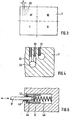
- the Fig. 1 and 2 show in a different perspective view and in a schematic manner the basic structure of a micro-machining machine 1 with a three-axis system (x, y, z) for the precision engraving of intaglio prints original.
- a rectilinear groove 3 is incorporated in the machine bed 2 .
- the orientation of this groove 3 corresponds to the x-axis.
- the cross table 4 is guided and thereby moved along the x-axis.
- the cross table 4 has a groove 5, whose Alignment of the z-axis corresponds and which is positioned exactly perpendicular to the groove 3 and thus to the x-axis.
- a holder 6 In the groove 5 of the XY stage, a holder 6 is guided, which receives the suction plate 7.
- the suction plate 7 serves as the actual workpiece holder, on which the plates to be processed are clamped by means of negative pressure. It is perpendicular to the plane formed by the x and z axes.
- On the holder 6 and the tool magazine 8 may be mounted, which serves to receive a variety of engraving tools.
- a columnar vertical support 9 On the machine bed 2, a columnar vertical support 9 is further arranged, which has a vertically extending groove 10 which extends along the y-axis.
- the processing module 11 is guided, which also includes the engraving tool.
- a guide column with squirrel cage parallel to the vertical support 9, can be used to form the y-axis. In the groove of the vertical support then the linear motor is housed. Advantage of this arrangement is the lightweight squirrel cage with optimal power distribution.
- the machine bed 2, the cross table 4, the holder 6, the suction plate 7 and the vertical support 9 are preferably made of natural hard stone, such as granite. Their surfaces are at least in the areas where other machine components are moved, executed extremely flat, preferably ground and lapped.
- the mutually perpendicular grooves 3, 5 and 10 take in the Fig. 1 and 2 not shown linear motors and the hydrostatic bearing on. These bearings and drives allow an absolute positioning accuracy in the range of ⁇ 5 ⁇ m and better with a repeat accuracy of approx. ⁇ 0.5 ⁇ m and better. In addition, such a combination avoids the so-called "stick-slip effect" and allows a free and very smooth starting and moving along the three axes.
- each axle is equipped with its own drive, the movements can be independent of each other.
- the described arrangement ensures in particular that a vertical movement of the tool along the y-axis is completely independent and uninfluenced by a horizontal movement of the workpiece in the xz-plane.
- damping elements such as air spring elements 12.
- the suction plate 7 is shown in plan view.
- a surface of the suction plate 7 is provided at a distance a, which may be for example about 10 mm, with suction openings 20, through which a workpiece is fixed on the plate surface.
- the suction openings extend over the entire surface, but are shown in the drawing only in the upper left corner of the suction plate 7.
- the suction plate 7 is preferably dimensioned such that the clamping surface covered by the suction openings 20 has a dimension of 500 ⁇ 600 mm and thereby also allows the processing of relatively large printing plate original.
- the clamping surface is preferably divided into individual quadrants, which in Fig. 3 are denoted by I to IV. The individual quadrants can have a different size and they are individually and independently controllable.
- the division into the individual quadrants is preferably carried out such that in a quadrant, for example I, small plates with a standard size of 250 x 250 mm can be clamped without additional cover.
- Fig. 4 a section of a cross section through the suction plate 7 is shown.
- the suction openings 20 are connected via bores 22 with vacuum channels 23, which may extend in line or in columns through the suction plate 7.
- the vacuum channels 23 are preferably arranged offset, so that they extend in different depths.
- the suction openings 20 are therefore made as small as possible and, for example, have a diameter of about 1 mm.
- the clamping surface with the vacuum channels 23 is first connected by holes 22 which have a larger diameter and thus are easier to manufacture.
- holes 22 Preferably, at least two rows of holes 22 are connected to a vacuum channel 23. This avoids that the suction plate is mechanically weakened by too many channels 23 too much.
- the outlet openings of the holes 22 on the clamping surface are provided with additional pressed or glued sleeves, preferably made of brass, which reduce the effective outlet opening.
- the inner sleeve diameter forms the actual suction opening 20.
- the clamping surface of the suction plate 7 can be lapped after the introduction of the sleeves 21, whereby an exact flatness of the clamping surface is ensured even in this preferred embodiment.
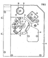
- Fig. 5 shows a plan view of the processing module 11, in the representation of Fig. 2 in the direction of the z-axis.
- the processing module 11 includes, inter alia, the machining spindle 30, on which a collet with the engraving tool 31 is located.
- spray nozzles 32 for supplying a cooling and / or lubricating medium, which are aligned with the tip of the engraving tool 31, and a suction device 33 to dissipate spray of the coolant or lubricant and chips.
- a non-contact distance sensor 34 is preferably arranged.
- Suitable distance sensors are, for example, eddy current sensors, capacitive distance sensors or light scanners. These measure the length growth, ie the axial position change of the machining spindle in the direction of the z-axis and provide the correction value S0 for the z-coordinate.
- the resolution of such distance sensors for measuring the change in length of the machining spindle is about 0.1 microns.
- the processing module 11 is equipped with observation devices 35, 36.
- a video microscope 35 is aligned via an angle mirror on the tool tip and the processing area.
- a sufficient illumination of the observed area provides as a means of illumination 37, for example, a flexible light guide.
- the image signal of the video microscope 35 is forwarded to a monitor and allows playback with a preferably 50 to 100 times the total magnification.
- another video microscope 36 can be directed in the direction of the z-axis onto the workpiece surface.
- This surveying system is preferably equipped with a further illumination means 38 and for protecting the objective with a rotatable cover.
- the cover can be rotated so that the opening 39 exposes the lens.
- the surveying system allows, for example by a connected monitor, preferably a computer with frame grabber and image processing software, the precise measurement of even the finest engraving by an approximately 400- to 600-fold total magnification.
- the entire processing module 11 is guided on the vertical support 9 in the groove 10 or on the guide column and moved by a linear motor in the direction of the y-axis on the vertical support.
- Fig. 6 is shown schematically the automatic tool change in the tool magazine 8.
- a section from a cross section through the tool magazine 8 is reproduced, by means of which the mounting and positioning of the engraving tool 31 is clarified.
- the engraving tool must be clamped into the tool holder with a predetermined, protruding length. For this it is necessary to store the tools so that the processing tip occupies a defined position. On the other hand, it must be ensured that the sensitive tool cutting edge is undamaged and therefore stored without contact.
- the engraving tool 31 can be introduced in the automated tool change through an opening 40 which is slightly larger than the tool diameter, with the processing tip in a cavity of the tool magazine 8.
- the clamping element 42 is preferably designed as a rubber O-ring.
- the sliding sleeve 44 forms a stop for the cutting-side end of the engraving tool 31 and positions the inserted tool in a defined, predetermined position. By a central bore in the sliding sleeve 44 ensures that the cutting edge is mounted without contact at the top of the engraving tool 31.
Landscapes
- Engineering & Computer Science (AREA)
- Manufacturing & Machinery (AREA)
- Manufacture Or Reproduction Of Printing Formes (AREA)
- Laminated Bodies (AREA)
- Application Of Or Painting With Fluid Materials (AREA)
- Shaping Of Tube Ends By Bending Or Straightening (AREA)
Abstract
Description
Die Erfindung betrifft ein Verfahren zur Herstellung von Stichtiefdruckplatten und eine Vorrichtung zur Herstellung dieser Platten.The invention relates to a method for producing intaglio printing plates and a device for producing these plates.
Unter Druckplatten im Sinne der Erfindung sind nicht nur Druckplatten, insbesondere Stichtiefdruckplatten für den farbführenden Druck, sondern auch für den Blinddruck, so genannte Prägeplatten zu verstehen.Under pressure plates according to the invention are not only printing plates, in particular intaglio printing plates for the ink-carrying printing, but also for the blind printing, so-called embossing plates to understand.
Für den Tiefdruck verwendete Druckformen werden beispielsweise mittels chemischer oder mechanischer Verfahren hergestellt.For example, printing forms used for gravure printing are produced by means of chemical or mechanical processes.
So können z.B. die für den Rastertiefdruck typischen näpfchenartigen Vertiefungen mit fotochemischem Ätzverfahren, bei dem Säure auf die Druckformoberfläche einwirkt, erzeugt werden. Allerdings sind die Rasterstege zwischen den Näpfchen relativ druckempfindlich, so dass diese beim Druckvorgang in Mitleidenschaft gezogen oder sogar zerstört werden und so eine hohe Auflagenfestigkeit nicht gewährleistet ist (Bruckmann's Handbuch der Drucktechnik, S 171ff). Außerdem ist es nicht möglich, absolut identische Ätzungen zu wiederholen.Thus, e.g. the cup-like depressions typical for screen deep printing are produced by a photochemical etching process in which acid acts on the printing plate surface. However, the grid webs between the wells are relatively sensitive to pressure, so that they are affected during the printing process or even destroyed and so a high circulation strength is not guaranteed (Bruckmann's Handbook of Printing Technology, S 171ff). In addition, it is not possible to repeat absolutely identical etches.
Alternativ zur chemischen Bearbeitung bieten sich verschiedene mechanische Bearbeitungsverfahren für eine Druckform an.As an alternative to chemical processing, various mechanical processing methods are available for a printing plate.
Insbesondere beim Druck hochwertiger Druckerzeugnisse, wie Wertpapiere oder Banknoten, werden Bildmotive traditionell in zeitaufwändiger Handarbeit mithilfe eines Stichels in eine Metallplatte, wie beispielsweise Stahl oder Kupfer, eingraviert. Beim Stichtiefdruck werden die Graustufen des Bildmotivs mit unterschiedlich breiten und/ oder tiefen Linien und einer unterschiedlichen Anzahl von Linien pro Fläche dargestellt.In particular, when printing high-quality printed products, such as securities or banknotes, image motifs are traditionally engraved in a time-consuming manual work using a stylus in a metal plate, such as steel or copper. In intaglio printing, the grayscale of the image motif is displayed with lines of different widths and / or depths and a different number of lines per area.
Neben der händischen Bearbeitung von Druckplatten kann die Gravur eines Druckzylinders auch maschinell erfolgen.In addition to the manual processing of printing plates, the engraving of a printing cylinder can also be done by machine.
Dabei werden, wie beispielsweise in der
Mit der Zerlegung der Bildvorlage in Grauwerte und deren Umsetzung auf der Druckplatte durch Näpfchen gehen jedoch die wesentlichen für den Stichtiefdruck erforderlichen Komponenten verloren, da mithilfe der Rastertechnik lediglich punktweise Farbe auf den Druckträger übertragen werden kann. Der Stichtiefdruck zeichnet sich jedoch gerade dadurch aus, dass auf dem Druckträger ein kontinuierliches, mit dem Farbauftrag fühlbares Liniendruckmuster übertragen wird, das sich insbesondere durch seine filigrane Linienführung auszeichnet.With the decomposition of the gray-scale image template and its implementation on the printing plate by means of wells, however, the essential components required for intaglio printing are lost, since only point-by-point ink can be transferred to the print substrate with the aid of the screening technique. However, intaglio printing is characterized in particular by the fact that a continuous line print pattern, which can be felt with the application of color, is transferred to the print substrate, which is particularly distinguished by its filigree lines.
Die
Eine Vorrichtung zum maschinellen Bearbeiten von Werkstücken beschreibt die
Aus
Aus
Zwar ist es möglich, mit den im Stand der Technik beschriebenen Verfahren und Vorrichtungen Werkstücke zu bearbeiten bzw. Druckplatten zu fertigen, allerdings ist eine extrem hohe Präzision nicht zu erreichen. Da es sich bei den Gravuren um sehr filigrane Strukturen mit eng geschwungenen Linien handeln kann, wird von der Bearbeitungsvorrichtung auch im Mikrobereich eine hohe Dynamik, optimaler Gleichlauf der Achsen und eine ausgezeichnete Wiederholgenauigkeit und Langzeitstabilität gefordert.Although it is possible to work with the methods and devices described in the prior art workpieces or to manufacture printing plates, but an extremely high precision can not be achieved. Since the engravings can be very filigree structures with narrowly curved lines, the machining device also requires high dynamics, optimum synchronization of the axes and excellent repeatability and long-term stability in the micro range.
Die Aufgabe der Erfindung besteht daher darin, ein Verfahren zur Herstellung von Druckplatten zur Verfügung zu stellen, wobei die druckenden bzw. prägenden Konturen der Platte eine Genauigkeit von vorzugsweise ca. mindestens 1 µm aufweisen.The object of the invention is to provide a method for the production of printing plates available, wherein the printing or embossing contours of the plate have an accuracy of preferably about at least 1 micron.
Eine weitere Aufgabe der Erfindung besteht darin, eine Vorrichtung zum Durchführen des Verfahrens bereitzustellen.Another object of the invention is to provide an apparatus for carrying out the method.
Die Lösung dieser Aufgaben ergibt sich aus den unabhängigen Ansprüchen. Weiterbildungen sind Gegenstand von Unteransprüchen.The solution to these problems arises from the independent claims. Further developments are the subject of dependent claims.
Gemäß der Erfindung werden bei der mechanischen Gravur von Stichtiefdruckplatten alle wesentlichen, den Graviervorgang beeinflussenden Parameter überwacht und gegebenenfalls geregelt, so dass sie über den gesamten Bearbeitungszeitraum einer Druckplatte ausreichend stabilisiert sind. Dadurch können Stichtiefdruckplatten hergestellt werden, deren Konturen eine Genauigkeit von vorzugsweise ca. mindestens 1 µm aufweisen. Zur Bearbeitung der Druckplatten kommt erfindungsgemäß eine Vorrichtung mit mindestens drei freien Achsen zum Einsatz, die unabhängig voneinander arbeiten und vorzugsweise jeweils von Linearmotoren angetrieben und auf hydrostatischen Lagern bewegt werden. Ein Werkstück wird mit samt einer Werkstückhalterung durch zwei voneinander unabhängige Antriebe in der Horizontalen entlang einer x- und z-Achse bewegt und eine vorgegebene y-Koordinate durch eine Vertikalbewegung eines Werkzeugs bzw. eines Bearbeitungsmoduls eingestellt. Mehrere Komponenten der Vorrichtung werden thermisch stabilisiert. Insbesondere zur Bestimmung der tatsächlichen Position der Werkzeugschneide relativ zur Werkstückoberfläche können mehrere Korrekturwerte ermittelt und bei der Steuerung der Eintauchtiefe des Gravierwerkzeugs berücksichtigt werden.According to the invention, in the mechanical engraving of intaglio printing plates, all essential parameters influencing the engraving process are monitored and optionally regulated, so that they are sufficiently stabilized over the entire processing period of a printing plate. As a result, intaglio printing plates can be produced whose contours have an accuracy of preferably approximately at least 1 μm. For processing the printing plates, according to the invention, a device with at least three free axes is used, which operate independently of one another and are preferably each driven by linear motors and moved on hydrostatic bearings. A workpiece is moved together with a workpiece holder by two independent drives in the horizontal along an x- and z-axis and set a predetermined y-coordinate by a vertical movement of a tool or a processing module. Several components of the device are thermally stabilized. In particular for determining the actual position of the tool cutting edge relative to the workpiece surface, a plurality of correction values can be determined and taken into account in the control of the insertion depth of the engraving tool.
Unter "Genauigkeit" einer Kontur sind gemäß der Erfindung dabei die Genauigkeiten der Abmessungen im gravierten Motiv zu verstehen, wie z.B. die Tiefe der Kontur, die Breite der Kontur, die Lage der Konturen zueinander und die Form der Kontur.By "accuracy" of a contour is to be understood according to the invention, the accuracies of the dimensions in the engraved motif, such. the depth of the contour, the width of the contour, the position of the contours to each other and the shape of the contour.
Um die erfindungsgemäß geforderte Genauigkeit zu erreichen, ist es vorteilhaft, die komplette Bearbeitungsvorrichtung möglichst schwingungsfrei oder zumindest schwingungsgedämpft aufzustellen. Weitere Vorteile ergeben sich durch den Einsatz von hydrostatischen Lagern für die zu bewegenden Komponenten, die eine hohe Steifigkeit bei gleichzeitig sehr reibungsarmer Bewegung ermöglichen. Während Gleit- oder Rolllager beim Anfahren, d.h. bei Bewegungsbeginn oder bei einer Umkehr der Bewegungsrichtung durch Haftungskräfte hervorgerufene, unkontrollierte ruckartige Bewegungen erzeugen (so genannter Stick-Slip-Effekt), ermöglichen hydrostatische Lager eine sehr gleichmäßige und ruckfreie Bewegung und damit auch eine genauere Positionierung. Hydrostatische Lager können beispielsweise in Längsnuten integriert werden, die den Bewegungsrichtungen bzw. Achsen der Bearbeitungsvorrichtung entsprechen. Einzelne Komponenten der Bearbeitungsvorrichtung können dadurch auf einem Ölfilm schwimmend gelagert, bewegt und positioniert werden.In order to achieve the required accuracy according to the invention, it is advantageous to set up the entire processing device as free of vibration as possible or at least damped by vibration. Further advantages result from the use of hydrostatic bearings for the components to be moved, which allow a high rigidity with very low-friction movement. While sliding or rolling bearings at start, i. At the beginning of the movement or when reversing the direction of movement caused by adhesion forces, uncontrolled jerky movements (so-called stick-slip effect), allow hydrostatic bearings a very smooth and smooth movement and thus a more accurate positioning. Hydrostatic bearings can be integrated, for example, in longitudinal grooves, which correspond to the directions of movement or axes of the processing device. Individual components of the processing device can thereby be stored, moved and positioned floating on an oil film.
Zur Erzielung der angestrebten Bearbeitungsgenauigkeit werden erfindungsgemäß die Temperaturen wichtiger Komponenten überwacht. Unkontrollierte Temperaturschwankungen oder -änderungen können die unterschiedlichsten Ursachen haben und auch lediglich lokal an einzelnen Komponenten auftreten. Aufgrund der Wärmeausdehnungs-Koeffizienten der betroffenen Materialien können sie zu unkontrollierten Veränderungen der Abmessungen führen und beeinflussen dadurch das Bearbeitungsergebnis der Maschine, bei dem höchste Präzision gefordert wird, auf negative Weise. Erfindungsgemäß werden die Temperaturen wichtiger Komponenten während des Bearbeitungsvorgangs eines Werkstücks überwacht. Besonders kritische Temperaturen werden aktiv mittels geeigneter Thermostate und Temperiereinrichtungen auf eine vorgegebene Solltemperatur geregelt. Dies betrifft insbesondere die Temperatur der Bearbeitungsspindel und deren Halterung, der Linearmotoren und deren Kühlwasser, der Werkstückhalterung (Vakuumplatte) sowie die Lager der drei Bewegungsachsen und des Öls der hydrostatischen Lager. Zur Regelung einer Temperatur kann die Isttemperatur in Intervallen von 1 s bis 5 min gemessen werden, typisch sind Messintervalle von etwa 10 s. Die Regelgenauigkeit ist vorzugsweise ≤± 1°, besonders bevorzugt ≤ ±0,5°, äußerst bevorzugt ≤ ± 0,1°C. Eine hohe Regelgenauigkeit und Konstanz der geregelten Temperaturen ist erforderlich, weil sich gezeigt hat, dass bei den gegebenen Abmessungen und Materialien bereits eine Temperaturschwankung von ca. 5°C an einer Achse zu einer Abweichung von bis zu 6 µm führen kann.To achieve the desired machining accuracy, the temperatures of important components are monitored according to the invention. Uncontrolled temperature fluctuations or changes can have a variety of causes and also occur only locally on individual components. Due to the coefficients of thermal expansion of the materials involved, they can lead to uncontrolled dimensional changes and thereby adversely affect the machining result of the machine where the highest precision is required. According to the invention, the temperatures of important components are monitored during the machining process of a workpiece. Particularly critical temperatures are actively controlled by means of suitable thermostats and tempering to a predetermined target temperature. This applies in particular to the temperature of the machining spindle and its holder, the linear motors and their cooling water, the workpiece holder (vacuum plate) and the bearings of the three axes of movement and the oil of the hydrostatic bearings. To control a temperature, the actual temperature can be measured at intervals of 1 s to 5 min, typically measuring intervals of about 10 s. The control accuracy is preferably ≦ ± 1 °, more preferably ≦ ± 0.5 °, most preferably ≦ ± 0.1 ° C. A high control accuracy and constancy of the controlled temperatures is required because it has been shown that given the dimensions and materials already a temperature fluctuation of about 5 ° C on an axis can lead to a deviation of up to 6 microns.
Weitere wichtige Parameter für die hoch präzise Bearbeitung eines Werkstücks, wie einer Druckplatte, sind neben den x-, y-Bearbeitungskoordinaten des Werkstücks auch der Unterdruck, mit dem das Werkstück an die Werkstückhalterung angesaugt wird, sowie die später erläuterte dynamische Tiefenkorrektur der Antriebswelle des Gravierstichels. Vorzugsweise werden diese kritischen Parameter während der Bearbeitung einer Druckplatte aufgezeichnet und protokolliert. Damit ist es möglich, den Einfluss von Schwankungen oder Störungen bei einzelnen Parametern auf das bearbeitete Werkstück nachzuvollziehen. Durch das Mitprotokollieren der x-, y-Koordinaten während des Graviervorgangs ist es auch möglich, erst zu einem späteren Zeitpunkt entdeckte Fehler in der Gravur einer Druck- oder Prägeplatte der Abweichung eines aufgezeichneten Parameters, beispielsweise einer Temperaturschwankung, zuzuordnen. Für die Aufzeichnung, Speicherung und visuelle Darstellung des zeitlichen Verlaufs der protokollierten Parameter wird vorzugsweise eine separate elektronische Datenverarbeitung, beispielsweise ein Personal Computer (PC) eingesetzt. Die Langzeitprotokollierung von kritischen Parametern hat den Vorteil, dass bei aufgetretenen Fehlern auch nachträglich die Ursachen hierfür ermittelt werden können. Dies ist insbesondere bei Druck- und Prägeplatten, die besonders groß sind und/ oder ein besonders komplexes oder filigranes Muster aufweisen, von großem Vorteil, da deren Bearbeitungszeiten mehrere Tage betragen können.Other important parameters for the high-precision machining of a workpiece, such as a pressure plate, in addition to the x, y machining coordinates of the workpiece and the negative pressure, with which the workpiece is sucked to the workpiece holder, and the later explained dynamic depth correction of the drive shaft of the engraving stylus , Preferably, these critical parameters are recorded and logged during processing of a printing plate. This makes it possible to understand the influence of fluctuations or disturbances in individual parameters on the machined workpiece. By logging the x, y coordinates during the engraving process, it is also possible to associate errors detected in the engraving of a printing or embossing plate at a later time with the deviation of a recorded parameter, for example a temperature fluctuation. For the recording, storage and visual representation of the time course of the logged parameters is preferably a separate electronic data processing, such as a personal computer (PC) used. The long-term logging of critical parameters has the advantage that, if errors occur, the causes can also be determined subsequently. This is particularly advantageous in printing and embossing plates, which are particularly large and / or have a particularly complex or filigree pattern, since their processing times can be several days.
Höchste Präzision und Reproduzierbarkeit bei der Druckplattenbearbeitung erfordert eine voneinander unabhängige und möglichst mechanisch entkoppelte Bewegung entlang der einzelnen Raumachsen. Hierfür wird für jede der drei Raumachsen ein eigener, unabhängig arbeitender Antrieb eingesetzt. Die Bearbeitungsvorrichtung wird so ausgeführt, dass das Werkstück mit samt der Werkstückhalterung durch zwei voneinander unabhängige Antriebe in der Horizontalen entlang der x- und z-Achse bewegt werden kann. Eine vorgegebene y-Koordinate wird durch eine Vertikalbewegung des Werkzeugs bzw. des Bearbeitungsmoduls eingestellt. Die Bewegung des Werkzeugs entlang der y-Achse erfolgt entlang einer separaten, säulenförmigen Halterung und ist dadurch mechanisch vollständig von der Bewegung entlang der x- und z-Koordinaten entkoppelt.Highest precision and reproducibility in the printing plate processing requires an independent and possibly mechanically decoupled movement along the individual spatial axes. For this purpose, a separate, independently operating drive is used for each of the three spatial axes. The processing device is designed so that the workpiece together with the workpiece holder can be moved by two independent drives in the horizontal along the x- and z-axis. A predetermined y-coordinate is set by a vertical movement of the tool or the machining module. The movement of the tool along the y-axis takes place along a separate, columnar support and is thereby mechanically completely decoupled from the movement along the x and z coordinates.
Für die Genauigkeit und Reproduzierbarkeit der bearbeiteten Werkstücke kommt den Antrieben für die Bewegung entlang der einzelnen Achsen eine besondere Bedeutung zu. Da sich die an den einzelnen Achsen ergebenden Fehler bei der Werkstückbearbeitung addieren, wird erfindungsgemäß auf konventionell arbeitende mechanische Antriebe, die beispielsweise mit Zahnradgetrieben und Gewindestangen arbeiten, verzichtet. Eine besonders hohe Positionierungsgenauigkeit wird durch den Einsatz von Linearmotorantrieben erreicht, da diese kein mechanisches Spiel aufweisen. Vorzugsweise wird für jede Achse ein separater Antrieb eingesetzt. Besonders bevorzugt wird ein Linearmotor als Antrieb für Bewegungen entlang der y-Achse, wodurch die vertikale Positionierung des Werkzeugs erfolgt.For the accuracy and reproducibility of the machined workpieces, the drives are of particular importance for movement along the individual axes. Since the resulting on the individual axes errors in the workpiece machining add, according to the invention on conventionally operating mechanical drives, which operate for example with gear drives and threaded rods dispensed. A particularly high positioning accuracy is achieved by the use of linear motor drives, since they have no mechanical play. Preferably, a separate drive is used for each axis. Particularly preferred is a linear motor as a drive for movements along the y-axis, whereby the vertical positioning of the tool takes place.
Die Fixierung der zu bearbeitenden Werkstücke, wie Druckplatten, erfolgt vorzugsweise über eine ebene Ansaugplatte, die das Werkstück durch einen auf eine Seite einwirkenden Unterdruck kraftschlüssig fixiert. Die Ansaugplatte wird in ihrem Inneren von weitgehend parallelen, beispielsweise senkrecht angeordneten Kanälen durchzogen. Die Kanäle werden mit einer Einrichtung zur Erzeugung eines Unterdrucks, beispielsweise einer Vakuumpumpe, verbunden. Entlang der Kanäle sind Öffnungen angeordnet, die die Unterdruckkanäle mit der werkstückseitigen Oberfläche der Ansaugplatte verbinden. Diese Ansaugöffnungen werden vorzugsweise so angeordnet, dass sie gleichmäßig voneinander beabstandet sind. Der Abstand zwischen zwei benachbarten Ansaugöffnungen kann beispielsweise ca. 1 cm betragen. Die Ansaugöffnungen haben einen Durchmesser, der vorzugsweise nicht wesentlich größer als ca. 1 mm ist. Um die Stabilität und Steifigkeit der Ansaugplatte nicht durch zu viele oder zu dicht nebeneinander liegende Kanäle negativ zu beeinflussen, werden vorzugsweise wenigstens zwei benachbarte Reihen von Ansaugöffnungen mit dem gleichen Kanal verbunden.The fixation of the workpieces to be processed, such as printing plates, preferably takes place via a flat suction plate, which frictionally fixes the workpiece by means of a negative pressure acting on one side. The suction plate is traversed in its interior by largely parallel, for example vertically arranged channels. The channels are connected to a device for generating a negative pressure, for example a vacuum pump. Openings are arranged along the channels connecting the vacuum channels to the workpiece side surface of the suction plate. These suction openings are preferably arranged so that they are evenly spaced from each other. The distance between two adjacent intake ports may be, for example, about 1 cm. The suction openings have a diameter which is preferably not substantially greater than about 1 mm. In order not to adversely affect the stability and rigidity of the suction plate by too many or too closely adjacent channels, preferably at least two adjacent rows of suction openings are connected to the same channel.
Aus dem Stand der Technik bekannte Ansaugplatten werden aus Metall, vorwiegend Aluminiumplatten, gefertigt. Aufgrund der hohen Wärmeleitfähigkeit und der verhältnismäßig großen Wärmeausdehnungskoeffizienten von Metallen, und insbesondere von Aluminium, können dadurch große Temperaturschwankungen und Längenänderungen in das Werkstück eingebracht werden, was zu nicht vernachlässigbaren Fehlern bei einer Präzisionsgravur führt. Bei der erfindungsgemäßen Bearbeitungsvorrichtung kommt deshalb vorzugsweise eine Ansaugplatte zum Einsatz, die aus Naturstein, vorzugsweise Granit, gefertigt ist. Platten aus Naturstein, und insbesondere aus Granit, wirken außerdem schwingungsdämpfend und zeichnen sich durch eine besonders hohe mechanische Steifigkeit aus. Ihre Oberfläche kann extrem plan gefertigt werden und sie weisen eine hohe Wärmekapazität bei gleichzeitig geringer Wärmeleitfähigkeit aus. Auch dies führt zu geringeren Temperaturschwankungen am Werkstück.Suction plates known from the prior art are made of metal, predominantly aluminum plates. Due to the high thermal conductivity and the relatively large thermal expansion coefficients of metals, and in particular of aluminum, thereby large temperature fluctuations and changes in length can be introduced into the workpiece, resulting in non-negligible errors in a precision engraving. In the processing device according to the invention therefore preferably a suction plate is used, which is made of natural stone, preferably granite. Natural stone slabs, and in particular granite slabs, also have a vibration-damping effect and are characterized by particularly high mechanical rigidity. Their surface can be made extremely flat and they have a high heat capacity with low thermal conductivity. This also leads to lower temperature fluctuations on the workpiece.
Da es insbesondere in Natur- oder Hartsteinplatten Probleme bereiten kann Ansaugkanäle mit einem sehr kleinen Durchmesser von beispielsweise 1 mm zu bohren, können die Bohrungen auch größer ausgeführt und nachträglich mit einer z.B. eingeklebten oder eingepressten Hülse versehen werden. Die einfacher zu bearbeitenden Hülsen sind dann entlang ihrer Längsachse mit einem Kanal mit dem gewünschten Durchmesser (beispielsweise 1 mm) zu versehen.Since it can cause problems especially in natural or hard stone slabs to drill intake ducts with a very small diameter, for example, 1 mm, the holes can also be made larger and subsequently with an example. be glued or pressed sleeve provided. The easier to handle sleeves are then along their longitudinal axis with a channel of the desired diameter (for example, 1 mm) to be provided.
Die zu bearbeitenden Werkstücke, wie Platten und Bleche, weichen von ihrer idealen Sollgeometrie ab und weisen Schwankungen in der Dicke und der Ebenheit ihrer Oberfläche auf. Um die erfindungsgemäß erforderliche Genauigkeit bei der Bearbeitung von Druckplatten zu erreichen, werden diese Unregelmäßigkeiten und Abweichungen der Werkstückoberfläche bei der Berechnung der Eintauchtiefe des Gravierwerkzeugs vorzugsweise berücksichtigt. Theoretisch lassen sich beliebig große Unebenheiten im Werkstück ausgleichen. In der Praxis ist mit Abweichungen bis zu ± 100 µm zu rechnen, wobei Werte um ± 60 µm üblich sind. Dazu wird vor Beginn der Gravur das dreidimensionale Höhenprofil der Werkstückoberfläche ermittelt. Durch eine Vielzahl einzelner Messpunkte, die vorzugsweise ein sich regelmäßig über die Werkstückoberfläche erstreckendes Gitter bilden, sind die Koordinaten einzelner Stützstellen bekannt, während die Position der Werkstückoberfläche für zwischen den Messpunkten liegende Stellen rechnerisch interpoliert werden kann. Die Anzahl der Messpunkte kann bei 40.000 liegen. Bei gängigen Druckplattenformaten werden meist 20.000 Messpunkte ermittelt. Die Oberflächenabtastung des Werkstücks liefert somit einen Korrekturwert W0 für die Berechnung und Steuerung der Eintauchtiefe des Gravierwerkzeugs. Diese Bewegung des Werkzeugs relativ zum Werkstück erfolgt in Richtung der z-Achse.The workpieces to be processed, such as plates and sheets, deviate from their ideal target geometry and exhibit variations in the thickness and the flatness of their surface. In order to achieve the precision required according to the invention in the processing of printing plates, these irregularities and deviations of the workpiece surface are preferably taken into account in the calculation of the immersion depth of the engraving tool. Theoretically, any unevenness in the workpiece can be compensated for. Deviations of up to ± 100 μm are to be expected in practice, with values around ± 60 μm being common. For this purpose, the three-dimensional height profile of the workpiece surface is determined before the engraving begins. By a plurality of individual measuring points, which preferably form a regularly extending over the workpiece surface grid, the coordinates of individual support points are known, while the position of the workpiece surface can be interpolated arithmetically for points lying between the measuring points. The number of measuring points can be around 40,000. With common printing plate formats usually 20,000 measuring points are determined. The surface scan of the workpiece thus provides a correction value W0 for the calculation and control of the insertion depth of the engraving tool. This movement of the tool relative to the workpiece takes place in the direction of the z-axis.
Einen weiteren Korrekturwert für die z-Koordinate erhält man, wenn auch die axiale Positionsveränderung der Bearbeitungsspindel berücksichtigt wird. Die während des Betriebs auftretenden axialen Positionsänderungen der Spindel haben zwei Hauptursachen. Zum einen verändert sich die Lage der Spindel in ihrem Axiallager in Abhängigkeit von der Drehzahl des Spindelantriebs und zum anderen führt eine Erwärmung der Spindel durch den Wärmeverlust des Antriebs zu einer axialen Längenausdehnung. An der Bearbeitungsspindel ist das Gravierwerkzeug z. B. mit einer Spannzange befestigt. Die beiden genannten Einflüsse führen am vorderen, werkzeugseitigen Ende zu einer axialen Positionsänderung der Bearbeitungsspindel, welche die Eintauchtiefe (d.h. die tatsächliche z-Koordinate) der Spitze des Gravierwerkzeugs verändern. Wird die axiale Position der Spindel in z-Richtung während des Betriebs fortlaufend an einem möglichst werkzeugnahen Punkt ermittelt, können diese Einflüsse durch einen entsprechenden Korrekturwert S0 für die z-Koordinate eliminiert werden. Dadurch können lange und störende Warmlaufphasen zur Erreichung konstanter Verhältnisse unterbleiben. Vorzugsweise erfolgt die Positionsmessung direkt an der Werkzeugspitze.A further correction value for the z-coordinate is obtained, even if the axial position change of the machining spindle is taken into account. The axial position changes of the spindle occurring during operation have two main causes. On the one hand, the position of the spindle changes in its axial bearing as a function of the rotational speed of the spindle drive and, on the other hand, heating of the spindle by the heat loss of the drive leads to an axial length expansion. On the machining spindle, the engraving tool z. B. attached with a collet. The two mentioned influences lead to an axial position change of the machining spindle at the front, tool-side end, which change the immersion depth (i.e., the actual z-coordinate) of the tip of the engraving tool. If the axial position of the spindle in the z-direction during operation is continuously determined at a point close to the tool as possible, these influences can be eliminated by a corresponding correction value S0 for the z-coordinate. This can avoid long and annoying warm-up phases to achieve constant conditions. The position measurement is preferably carried out directly on the tool tip.
Durch die beiden Korrekturwerte W0 und S0 für die z-Koordinate ist eine hoch präzise und reproduzierbare Bearbeitung der Werkstückoberflächen möglich, wobei insbesondere die für die Tiefdruckplattenfertigung sehr wichtige Solltiefe der bearbeiteten Bereiche präzise eingehalten werden kann.Due to the two correction values W0 and S0 for the z-coordinate, a highly precise and reproducible machining of the workpiece surfaces is possible, whereby in particular the desired depth of the machined areas, which is very important for gravure plate production, can be precisely maintained.
Um bei der Werkstückbearbeitung eine vorgegebene Solltiefe exakt erreichen zu können, ist es außerdem erforderlich, die Position bzw. z-Koordinate Z0 der Werkzeugspitze genau zu kennen. Wird die Position der Spitze im eingespannten Zustand ermittelt, ergibt sich daraus die effektive Werkzeuglänge. Wird die Position nicht nur zu Beginn eines Bearbeitungsvorgangs ermittelt, sondern in vorgegebenen Abständen (beispielsweise alle 30 min) oder vor bestimmten Bearbeitungsabschnitten auch während der Bearbeitung, kann anhand auftretender Veränderungen der Position der Werkzeugspitze auf übermäßigen Verschleiß oder Beschädigung, beispielsweise durch Bruch der Schneidkante des Gravierwerkzeugs, geschlossen werden.In order to be able to achieve a given target depth precisely during workpiece machining, it is also necessary to know exactly the position or z-coordinate Z0 of the tool tip. If the position of the tip is determined in the clamped state, this results in the effective tool length. If the position is determined not only at the beginning of a machining operation, but at predetermined intervals (for example every 30 minutes) or during certain machining stages during machining, changes in the position of the tool tip may indicate excessive wear or damage, for example due to breakage of the cutting edge of the tool Engraving tool, to be closed.
Zur Ermittlung der effektiven Werkzeuglänge wird die Spitze des Gravierwerkzeugs gegen ein Messsystem gefahren und die Position der Werkzeugspitze in z-Richtung mit höchster Präzision erfasst. Für die Messung kommen vorzugsweise mechanische Messsysteme infrage, die eine plane Anschlagfläche aufweisen, gegen die die Werkzeugspitze gefahren wird. Die Messkraft sollte 0,1 N nicht überschreiten und ist vorzugsweise ≤ 0,01 N. Solche Werte werden beispielsweise von luftgelagerten Messtastern erreicht. Auch berührungslos arbeitende optische Messsysteme, bei denen die Lage der Werkzeugspitze mittels einer geeigneten Optik und Mitteln und Methoden der Bildverarbeitung erkannt und vermessen wird, können eingesetzt werden.To determine the effective tool length, the tip of the engraving tool is moved against a measuring system and recorded the position of the tool tip in the z-direction with the highest precision. For the measurement are preferably mechanical measuring systems in question, which have a flat stop surface against which the tool tip is driven. The measuring force should not exceed 0.1 N and is preferably ≤ 0.01 N. Such values are achieved, for example, by air-borne measuring probes. Non-contact optical measuring systems in which the position of the tool tip is detected and measured by means of suitable optics and means and methods of image processing can also be used.
Zur Erzeugung komplexer Strukturen in der Oberfläche von Druck- und Prägeplatten werden vorzugsweise Gravierwerkzeuge mit unterschiedlicher Schneidengeometrie eingesetzt. Je nach gewünschtem Effekt im Druck- oder Prägebild wird für die Gravur des betreffenden Bereichs der Platte ein geeignetes Werkzeug ausgewählt. Für die Gravur sehr feiner Strukturen werden bevorzugt Werkzeuge eingesetzt, deren Schneiden einen kleinen Spitzenradius und einen kleinen Spitzenwinkel aufweisen (beispielsweise 5 bis 50 µm und 20 bis 120°). Für das bloße Abräumen größerer Flächenbereiche werden dagegen Werkzeuge mit größerem Spitzenradius und größerem Spitzenwinkel bevorzugt. Um während der Bearbeitung einen unkomplizierten und schnellen Wechsel der Werkzeuge zu ermöglichen, wird die Maschine vorzugsweise mit einem Magazin zur Aufnahme einer Vielzahl von Werkzeugen und einer Vorrichtung für einen automatischen Werkzeugwechsel ausgestattet. Dadurch können die durch Werkzeugwechsel verursachten Unterbrechungen des Bearbeitungsprozesses auf ein Minimum reduziert und die Gesamtdauer der Druckplattenbearbeitung verkürzt werden. Das Werkzeugmagazin in Verbindung mit der Wechselvorrichtung ermöglicht nicht nur den schnellen und unkomplizierten Austausch von Werkzeugen unterschiedlicher Geometrie, sondern auch den Austausch von beschädigten oder verschlissenen Werkzeugen. In einem Magazin können beispielsweise ein Dutzend unterschiedliche und/oder gleiche Gravierstichel bereitgehalten werden. Das Werkzeugmagazin ist vorzugsweise starr und unbeweglich ausgeführt. D.h. bei einem Werkzeugwechsel wird nicht das Magazin bewegt, so dass das neue Werkzeug an die Werkzeughalterung herangeführt wird, sondern die Werkzeughalterung, beispielsweise eine Spannzange bewegt sich zu dem Werkzeug in der vorgesehenen Wechselposition. Um die empfindlichen Schneiden der Gravierwerkzeuge nicht zu beschädigen, sind die Werkzeuge beim Wechseln so zu führen und im Magazin so zu fixieren, dass die Schneidkanten nicht berührt werden.To produce complex structures in the surface of printing and embossing plates engraving tools are preferably used with different cutting geometry. Depending on the desired effect in the print or embossed image, a suitable tool is selected for the engraving of the relevant area of the plate. For the engraving of very fine structures, preference is given to using tools whose cutting edges have a small tip radius and a small tip angle (for example 5 to 50 μm and 20 to 120 °). For the mere clearing away of larger surface areas, however, tools with a larger tip radius and a larger tip angle are preferred. In order to enable an uncomplicated and quick change of the tools during processing, the machine is preferably equipped with a magazine for holding a plurality of tools and an apparatus for an automatic tool change. As a result, the interruptions of the machining process caused by tool changes can be reduced to a minimum and the overall duration of the printing plate processing can be shortened. The tool magazine in conjunction with the changing device not only allows the quick and easy replacement of tools of different geometry, but also the replacement of damaged or worn tools. In a magazine, for example, a dozen different and / or the same engraving stylus can be kept ready. The tool magazine is preferably rigid and immovable. That when a tool change the magazine is not moved, so that the new tool is brought to the tool holder, but the tool holder, such as a collet moves to the tool in the intended change position. In order not to damage the sensitive cutting edges of the engraving tools, the tools are to be guided during the change and fixed in the magazine so that the cutting edges are not touched.
Die Gravierwerkzeuge werden vorzugsweise aus verschleißfestem Material hergestellt. Hierfür kommen beispielsweise gesinterte Hartmetalle infrage, aber auch keramische Schneidwerkzeuge oder solche aus hochlegierten Werkzeugstählen mit einer diamantbeschichteten Schneide oder einer Schneide, die vollständig aus Diamantmaterial gefertigt wurde. Vorzugsweise ist die Härte des Gravierwerkzeugs ca. 10- bis 20-fach höher als die Härte des bearbeiteten Werkstücks (bezogen auf die Vickers-Härte).The engraving tools are preferably made of wear-resistant material. For this example, sintered hard metals in question, but also ceramic cutting tools or those made of high-alloy tool steels with a diamond-coated cutting edge or a cutting edge, which was made entirely of diamond material. Preferably, the hardness of the engraving tool is about 10 to 20 times higher than the hardness of the machined workpiece (based on the Vickers hardness).
Die Einheit aus Werkzeug, Werkzeughalterung und Werkzeugantrieb wird auch als Bearbeitungsspindel bezeichnet. Die Bearbeitungsspindel, die Spindelhalterung und weitere Komponenten sind im Bearbeitungsmodul zusammengefasst. Das komplette Bearbeitungsmodul kann bei der erfindungsgemäßen Vorrichtung in vertikaler Richtung, d.h. entlang der y-Achse bewegt werden. Diese Bewegung erfolgt vollkommen unabhängig von den Bewegungen entlang den anderen Achsen. Zur Gewährleistung eines störungsfreien Betriebs und dessen Kontrolle wird das Bearbeitungsmodul vorzugsweise mit verschiedenen zusätzlichen Einrichtungen ausgestattet, die nachfolgend beschrieben werden.The unit of tool, tool holder and tool drive is also referred to as a machining spindle. The machining spindle, the spindle holder and other components are combined in the machining module. The complete processing module can in the inventive device in vertical direction, ie moved along the y-axis. This movement is completely independent of the movements along the other axes. To ensure trouble-free operation and its control, the processing module is preferably equipped with various additional facilities, which are described below.
Wegen sehr hoher Drehzahlen des Werkzeugs und der Antriebsspindel, die mehr als 100.000/min. betragen können, wird das erforderliche Kühlmittel nicht als Flüssigkeitsstrahl zugeführt, sondern als Sprühnebel von einer oder mehreren Sprühvorrichtungen unter regelbarem, hohem Druck in den Arbeitsbereich der Werkzeugschneide eingesprüht. Beispielsweise auf der den Sprühvorrichtungen gegenüberliegenden Seite des Werkzeugs wird vorzugsweise eine Absaugvorrichtung montiert, wodurch die ungewollte Ausbreitung von Sprühnebeln verhindert wird. Als Kühlmedium werden vorzugsweise Fettalkohole eingesetzt.Because of very high speeds of the tool and the drive spindle, which exceeds 100,000 / min. can be supplied, the required coolant is not supplied as a liquid jet, but sprayed as a spray from one or more spray devices under controllable, high pressure in the working range of the tool cutting edge. For example, on the opposite side of the tool spraying devices, a suction device is mounted, whereby the unwanted propagation of spray is prevented. The cooling medium used is preferably fatty alcohols.
Zur in situ-Überwachung des Graviervorgangs wird der Bearbeitungsmodul vorzugsweise mit einer Beobachtungseinrichtung ausgestattet. Diese kann beispielsweise aus einem Video-Mikroskop bestehen, das über einen Winkelspiegel auf den Bearbeitungsbereich gerichtet ist. Um für ausreichende und konstante Beleuchtungsverhältnisse zu sorgen, kann der Bearbeitungsbereich durch zusätzliche, ebenfalls am Bearbeitungsmodul befestigte Beleuchtungsmittel ausgeleuchtet werden. Hierfür eignen sich beispielsweise flexible Lichtleiter.For in situ monitoring of the engraving process, the processing module is preferably equipped with an observation device. This can for example consist of a video microscope, which is directed via an angle mirror on the processing area. In order to ensure sufficient and constant lighting conditions, the processing area can be illuminated by additional, also attached to the processing module lighting means. For example, flexible light guides are suitable for this purpose.
Die erfindungsgemäße Vorrichtung wird vorzugsweise mit einer zweiten Beobachtungsvorrichtung ausgestattet, die ebenfalls am Bearbeitungsmodul montiert sein kann. Diese zweite Vorrichtung ist so ausgebildet, dass sie in der erforderlichen Genauigkeit zur Vermessung der bearbeiteten Werkstückoberfläche bzw. der erzeugten Gravuren eingesetzt werden kann. Auch diese zweite optische Einrichtung kann als Video-Mikroskop ausgeführt sein. Die Betrachtungsrichtung der optischen Vermessungseinheit ist vorzugsweise senkrecht auf die Werkstückoberfläche gerichtet.The device according to the invention is preferably equipped with a second observation device, which can also be mounted on the processing module. This second device is designed so that it can be used in the required accuracy for measuring the machined workpiece surface or the engraving produced. This second optical device can also be designed as a video microscope. The viewing direction of the optical measuring unit is preferably directed perpendicular to the workpiece surface.
Zur Vermeidung ungewollter und unkontrollierter Positionsänderungen im Bereich des Bearbeitungsmodules aufgrund von Temperaturschwankungen kann beispielsweise die Halterung der Bearbeitungsspindel durch einen Regelkreislauf auf konstanter Temperatur gehalten werden und/oder aus einem Material mit niedrigem Wärmeausdehnungs-Koeffizienten gefertigt sein. Hierfür kommen beispielsweise Naturstein, wie Granit, oder Eisennickellegierungen, wie Invar, in Betracht.To avoid unwanted and uncontrolled changes in position in the area of the processing module due to temperature fluctuations, for example, the holder of the machining spindle can be kept at a constant temperature by a control circuit and / or be made of a material with a low coefficient of thermal expansion. Natural stone, such as granite, or iron nickel alloys, such as Invar, come into consideration for this purpose.
Mithilfe des erfindungsgemäßen Verfahrens ist eine sehr hohe Bearbeitungsgenauigkeit und eine äußerst gute Reproduzierbarkeit bei der Herstellung von Druckplatten gewährleistet, was folglich die Produktionssicherheit erhöht und so wiederum die Produktivität verbessert. Gerade bei sehr großen Druckplatten mit komplexen Strukturen macht sich dies positiv bemerkbar. Originale für die klassische Abformung der für die eigentliche Produktion eingesetzten Druckplatten können mit dem erfindungsgemäßen Verfahren mit bisher nicht möglicher, höchster Präzision, also fast identisch reproduziert werden, falls die ursprünglichen Originale verschlissen oder beschädigt sind.By means of the method according to the invention, a very high machining accuracy and an extremely good reproducibility in the production of printing plates is ensured, which consequently increases production reliability and thus in turn improves productivity. Especially with very large printing plates with complex structures, this makes a positive impact. Originals for the classical impression of the printing plates used for the actual production can be reproduced with the inventive method with hitherto impossible, highest precision, so almost identical, if the original originals are worn or damaged.
Werden lasierenden Druckfarben verwendet, können hoch präzise gravierte Druck- bzw. Prägeplatten zur Steuerung des Farbtones im Druckbild vorteilhaft eingesetzt werden. Je tiefer die Gravur in der Druckplatte ist, desto mehr Farbe kann sie aufnehmen und um so mehr Farbe wird auf das zu bedruckende Substrat, meist Papier, übertragen. Je mehr Farbe übertragen wird, um so dunkler fällt der Farbton auf dem Substrat aus und umgekehrt. Insbesondere bei sehr hellen Farbtönen können bereits geringe Schwankungen in der Gravurtiefe zu Schwankungen im Farbton führen. Umso wichtiger ist es daher, ein exakt bestimmbare Gravurtiefe in der Druckplatte erzeugen zu können, wie sie die erfindungsgemäße Druckplatte aufweist.If translucent printing inks are used, highly precisely engraved printing or embossing plates can be advantageously used to control the color tone in the printed image. The deeper the engraving is in the printing plate, the more color it can absorb and the more ink is transferred to the substrate to be printed, usually paper. The more color that is transferred, the darker the hue on the substrate will be and vice versa. Even with very light shades, even slight variations in the engraving depth can lead to fluctuations in the hue. It is therefore all the more important to be able to produce an exactly determinable engraving depth in the printing plate, as it has the printing plate according to the invention.
Weitere Vorteile und Ausführungsformen werden anhand der Figuren näher erläutert. Es wird darauf hingewiesen, dass die Figuren lediglich schematisch den Aufbau der erfindungsgemäßen Bearbeitungsvorrichtung oder einzelner Komponenten darstellen. Die in den Figuren gezeigten Proportionen entsprechen nicht unbedingt den in der Realität vorliegenden Verhältnissen und dienen vornehmlich der Veranschaulichung. Dabei zeigt
- Fig. 1
- eine perspektivische Ansicht einer erfindungsgemäßen Gra- viermaschine,
- Fig. 2
- die Graviermaschine gemäß
Fig. 1 aus einer anderen Ansicht, - Fig. 3
- eine Ansaugplatte als Vakuumsparulvorrichtung für die Werk- stücke in Aufsicht,
- Fig. 4
- einen Querschnitt durch eine Ansaugplatte gemäß
Fig. 3 , - Fig. 5
- ein Bearbeitungsmodul einer erfindungsgemäßen Gravierma- schine mit Zusatzeinrichtungen in Aufsicht,
- Fig. 6
- ein Detail des Werkzeugmagazins im Querschnitt.
- Fig. 1
- 3 is a perspective view of a four-dimensional machine according to the invention,
- Fig. 2
- the engraving machine according to
Fig. 1 from another view, - Fig. 3
- a suction plate as Vakuumsparulvorrichtung for the workpieces in supervision,
- Fig. 4
- a cross section through a suction according to
Fig. 3 . - Fig. 5
- a processing module of an engraving machine according to the invention with additional devices in supervision,
- Fig. 6
- a detail of the tool magazine in cross section.
Die
Das Maschinenbett 2, der Kreuztisch 4, die Halterung 6, die Ansaugplatte 7 und der Vertikalträger 9 werden vorzugsweise aus Naturhartstein, wie Granit, gefertigt. Ihre Oberflächen sind zumindest in den Bereichen, auf denen andere Maschinenkomponenten bewegt werden, extrem plan ausgeführt, vorzugsweise geschliffen und geläppt. Die jeweils senkrecht zueinander angeordneten Nuten 3, 5 und 10 nehmen die in den
Um die Übertragung von Schwingungen zu vermeiden, ist die gesamte Maschine auf Dämpfungselemente, beispielsweise Luftfederelemente 12, gestellt.In order to avoid the transmission of vibrations, the entire machine is placed on damping elements, such as
In
In
Um auch sehr dünne und mechanisch wenig stabile Werkstücke einer Präzisionsbearbeitung unterziehen zu können, ist es erforderlich, dass diese sich im Bereich der Ansaugöffnungen nicht durchbiegen. Die Ansaugöffnungen 20 werden deshalb möglichst klein ausgeführt und haben beispielsweise einen Durchmesser von ca. 1 mm. Bei der bevorzugten Ausführungsform der Ansaugplatte in Naturhartstein, kann es jedoch Probleme bereiten, derart kleine Öffnungen in großer Anzahl in die Oberfläche einzubringen. Deshalb wird die Aufspannfläche mit den Unterdruckkanälen 23 zunächst durch Bohrungen 22 verbunden, die einen größeren Durchmesser aufweisen und dadurch leichter zu fertigen sind. Vorzugsweise werden wenigstens zwei Reihen von Bohrungen 22 mit einem Unterdruckkanal 23 verbunden. Dadurch wird vermieden, daß die Ansaugplatte durch eine zu große Anzahl von Kanälen 23 mechanisch zu sehr geschwächt wird. Die Austrittsöffnungen der Bohrungen 22 an der Aufspannfläche werden mit zusätzlichen eingepressten oder eingeklebten Hülsen, vorzugsweise aus Messing, versehen, die die effektive Austrittsöffnung verkleinern. Der innere Hülsendurchmesser bildet die eigentliche Ansaugöffnung 20. Die Aufspannfläche der Ansaugplatte 7 kann nach dem Einbringen der Hülsen 21 geläppt werden, wodurch auch bei dieser bevorzugten Ausführungsform eine exakte Planebenheit der Aufspannfläche gewährleistet ist.In order to subject very thin and mechanically unstable workpieces precision machining, it is necessary that they do not bend in the intake. The
Zur Beobachtung des Antastens der Gravierwerkzeugspitze auf der Werkstückoberfläche, des eigentlichen Bearbeitungsvorgangs, und zur genauen Vermessung der erzeugten Gravuren, ohne das Werkstück abspannen zu müssen, wird das Bearbeitungsmodul 11 mit Beobachtungseinrichtungen 35, 36 ausgestattet. Für das Beobachten des Antastens sowie der in-situ-Beobachtung des Bearbeitungsvorganges ist ein Videomikroskop 35 über einen Winkelspiegel auf die Werkzeugspitze und den Bearbeitungsbereich ausgerichtet. Für eine ausreichende Ausleuchtung des beobachteten Bereichs sorgt als Beleuchtungsmittel 37 beispielsweise ein flexibler Lichtleiter. Das Bildsignal des Videomikroskops 35 wird an einen Monitor weitergeleitet und ermöglicht eine Wiedergabe mit einer vorzugsweise 50- bis 100-fachen Gesamtvergrößerung. Als Präzisionsvermessungssystem für die erzeugten Gravuren kann ein weiteres Videomikroskop 36 in Richtung der z-Achse auf die Werkstückoberfläche gerichtet werden. Dieses Vermessungssystem wird vorzugsweise mit einem weiteren Beleuchtungsmittel 38 und zum Schutz des Objektivs mit einer drehbaren Abdeckung ausgestattet. Zur Vermessung kann die Abdeckung so gedreht werden, dass die Öffnung 39 das Objektiv freilegt. Das Vermessungssystem ermöglicht beispielsweise durch einen angeschlossenen Monitor, vorzugsweise ein Computer mit Framegrabber und Bildverarbeitungssoftware, die präzise Vermessung auch feinster Gravuren durch eine ca. 400- bis 600-fache Gesamtvergrößerung.To observe the probing of the engraving tool tip on the workpiece surface, the actual machining operation, and to accurately measure the generated engraving without having to chuck the workpiece, the
Das gesamte Bearbeitungsmodul 11 wird auf dem Vertikalträger 9 in der Nut 10 bzw. an der Führungssäule geführt und durch einen Linearmotor in Richtung der y-Achse auf dem Vertikalträger bewegt.The
In
Claims (40)
- A method for producing intaglio printing plates by mechanical engraving, wherein the machining is effected by means of at least three free axes movable independently of each other, characterized in that the temperatures of important components are continually monitored and if necessary regulated, so that a sufficient thermal stabilization is effected over the machining time period, and that a workpiece is moved together with a workpiece mount in the horizontal along an x- and z-axis by two mutually independent drives, and a specified y-coordinate is adjusted by a vertical motion of a tool or a machining module.
- The method according to claim 1, characterized in that the motions along the axes are guided on hydrostatic bearings.
- The method according to claim 2, characterized in that the temperature of the hydrostatic bearings and/or preferably their hydraulic oil is regulated.
- The method according to at least one of claims 1 to 3, characterized in that the motions and positionings along the axes are effected by linear motors.
- The method according to claim 4, characterized in that the temperature of the linear motors is regulated.
- The method according to at least one of claims 1 to 5, characterized in that the printing plate is held by a suction plate during machining.
- The method according to claim 6, characterized in that the temperature of the suction plate is regulated.
- The method according to at least one of claims 1 to 7, characterized in that the engraving tool is driven by a machining spindle with a speed of ≥ 100,000 rpm.
- The method according to claim 8, characterized in that the temperature of the machining spindle and/or of the spindle mount is regulated.
- The method according to at least one of claims 3 to 9, characterized in that the regulation accuracy for one or several, preferably all, of the temperatures is ≤ ± 1°C.
- The method according to at least one of claims 1 to 10, characterized in that before the onset of machining the actual position of the surface of the clamped workpiece is ascertained (W0).
- The method according to at least one of claims 1 to 11, characterized in that before the onset of, and optionally also during, machining the actual position of the cutter of the clamped engraving tool is ascertained (Z0).
- The method according to claim 12, characterized in that the position of the cutter is ascertained by means of an air-suspended probe.
- The method according to at least one of claims 8 and 9, characterized in that during machining the axial position of the machining spindle is ascertained (S0).
- The method according to claim 14, characterized in that the position of the machining spindle is measured by means of an eddy current sensor.
- The method according to at least one of claims 1 to 15, characterized in that at least one, preferably all, of the following quantities are logged or recorded during printing-plate machining: time, space coordinates (x, y, z), vacuum of the suction plate, temperatures of the regulated components, ambient temperature, axial position change of the machining spindle (S0), effective tool length (Z0), position of the workpiece surface (W0).
- The method according to at least one of claims 1 to 16, characterized in that the machining process is checked by an optical observation device.
- An apparatus for producing intaglio printing plates by mechanical engraving, wherein the apparatus has at least three free axes of motion movable independently of each other, characterized in that it has means for continually monitoring and if necessary regulating the temperatures of important components, so that a sufficient thermal stabilization is effected over the machining time period, and that a workpiece is movable together with a workpiece mount in the horizontal along an x- and z-axis by two mutually independent drives, and a specified y-coordinate is adjusted by a vertical motion of a tool or a machining module.
- The apparatus according to claim 18, characterized in that the vertical motion is completely decoupled mechanically from the horizontal motion.
- The apparatus according to claim 18 or 19, characterized in that the axes of motion have hydrostatic bearings.
- The apparatus according to claim 20, characterized in that it has a temperature regulation for the hydrostatic bearings and/or preferably their hydraulic oil.
- The apparatus according to at least one of claims 18 to 21, characterized in that it has linear motors for moving and positioning along the axes.
- The apparatus according to claim 22, characterized in that it has a temperature regulation for the linear motors.
- The apparatus according to at least one of claims 18 to 23, characterized in that it has a suction plate for holding the printing plate.
- The apparatus according to claim 24, characterized in that it has a temperature regulation for the suction plate.
- The apparatus according to either of claims 24 and 25, characterized in that on its clamping surface the suction plate has bores in which sleeves are fastened, and the inside diameters of the sleeves constitute the suction openings.
- The apparatus according to any of claims 24 to 26, characterized in that the suction openings of the suction plate have a diameter of 0.5 to 2 mm, preferably 1 mm.
- The apparatus according to at least one of claims 18 to 27, characterized in that it has a temperature regulation for the machining spindle.
- The apparatus according to at least one of claims 18 to 28, characterized in that it has means for scanning and capturing the position of the surface of the clamped workpiece.
- The apparatus according to claims 28 or 29, characterized in that it has means for capturing the axial position of the machining spindle.
- The apparatus according to claim 30, characterized in that it has an eddy current sensor for the position determination.
- The apparatus according to at least one of claims 18 to 31, characterized in that it has means for capturing the position of the cutter of the clamped engraving tool.
- The apparatus according to claim 32, characterized in that it has an air-suspended probe for the position determination.
- The apparatus according to claim 33, characterized in that the measuring force of the probe is ≤ 0.1 N.
- The apparatus according to at least one of claims 18 to 34, characterized in that it has means for an automated tool change.
- The apparatus according to at least one of claims 18 to 35, characterized in that it has a tool magazine which can receive a plurality of engraving tools.
- The apparatus according to claim 36, characterized in that the cutters of the engraving tools are mounted in the magazine in a defined position and contactlessly.
- The apparatus according to at least one of claims 18 to 37, characterized in that it has an optical observation device for the machining process.
- The apparatus according to at least one of claims 18 to 38, characterized in that it has an observation device for the optical measurement of the produced engravings.
- The apparatus according to at least one of claims 24 to 39, characterized in that the suction plate is made of natural stone, preferably granite.
Applications Claiming Priority (3)
| Application Number | Priority Date | Filing Date | Title |
|---|---|---|---|
| DE10260253 | 2002-12-20 | ||
| DE10260253A DE10260253A1 (en) | 2002-12-20 | 2002-12-20 | Method and device for producing intaglio printing plates and printing plate produced therewith |
| PCT/EP2003/014610 WO2004056568A2 (en) | 2002-12-20 | 2003-12-19 | Method and device for producing intaglio printing plates and a printing plate produced in such a manner |
Publications (3)
| Publication Number | Publication Date |
|---|---|
| EP1578604A2 EP1578604A2 (en) | 2005-09-28 |
| EP1578604B1 EP1578604B1 (en) | 2011-03-23 |
| EP1578604B2 true EP1578604B2 (en) | 2014-06-18 |
Family
ID=32404121
Family Applications (1)
| Application Number | Title | Priority Date | Filing Date |
|---|---|---|---|
| EP03782459.6A Expired - Lifetime EP1578604B2 (en) | 2002-12-20 | 2003-12-19 | Method and device for producing intaglio printing plates |
Country Status (6)
| Country | Link |
|---|---|
| EP (1) | EP1578604B2 (en) |
| AT (1) | ATE502775T1 (en) |
| AU (1) | AU2003290099A1 (en) |
| DE (2) | DE10260253A1 (en) |
| RU (1) | RU2348533C2 (en) |
| WO (1) | WO2004056568A2 (en) |
Families Citing this family (5)
| Publication number | Priority date | Publication date | Assignee | Title |
|---|---|---|---|---|
| US20070227384A1 (en) * | 2006-04-03 | 2007-10-04 | Mcgaire Mark D | Imaging and punching thermal control system |
| DE102007045015A1 (en) * | 2007-09-20 | 2009-04-02 | Giesecke & Devrient Gmbh | Apparatus and method for producing multi-use intaglio printing plates |
| RU2467859C1 (en) * | 2011-06-29 | 2012-11-27 | Федеральное Государственное Унитарное Предприятие "Гознак" (Фгуп "Гознак") | Method of forming 3d microstructures of engraving patter in functional layer of intaglio printing die functional layer at computer-aided engraving hardware-software complex |
| RU2624717C1 (en) * | 2016-03-11 | 2017-07-05 | Закрытое акционерное общество "Санкт-Петербургская Образцовая Типография" | Method of tool cliche producing |
| DE102021002867A1 (en) | 2021-06-02 | 2022-12-08 | Giesecke+Devrient Currency Technology Gmbh | Extended shelf life intaglio printing plate and method of making same |
Citations (11)
| Publication number | Priority date | Publication date | Assignee | Title |
|---|---|---|---|---|
| DE2508985A1 (en) † | 1974-03-01 | 1975-09-04 | Crosfield Electronics Ltd | METHOD AND DEVICE FOR MANUFACTURING A GRAVURE PRINTING CYLINDER |
| EP0595324A1 (en) † | 1992-10-28 | 1994-05-04 | Dainippon Screen Mfg. Co., Ltd. | Automatic real-time calibrator for electromechanical rotogravure stylus |
| EP0652075A2 (en) † | 1993-09-14 | 1995-05-10 | Eduard Huber Management Ag | Device for the machining of workpieces |
| WO1996023201A1 (en) † | 1995-01-23 | 1996-08-01 | Ohio Electronic Engravers, Inc. | Intaglio engraving method and apparatus |
| WO1997027026A1 (en) † | 1996-01-23 | 1997-07-31 | Renault-Automation | Logical design of a spindle holdertype machine tool for high-speed machining |
| WO1997048555A1 (en) † | 1996-06-17 | 1997-12-24 | Giesecke & Devrient Gmbh | Process for producing dies |
| US5731881A (en) † | 1994-11-04 | 1998-03-24 | Ohio Electronic Engravers, Inc. | Engraving method and apparatus using cooled magnetostrictive actuator |
| WO1999007554A1 (en) † | 1997-08-08 | 1999-02-18 | Heidelberger Druckmaschinen Ag | Method for positioning engraving organs |
| WO1999030482A1 (en) † | 1997-12-09 | 1999-06-17 | Heidelberger Druckmaschinen Aktiengesellschaft | Method for operating an engraving member |
| DE10101134A1 (en) † | 2001-01-12 | 2002-07-18 | Heidelberger Druckmasch Ag | Cooling device for cooling an engraving system |
| US20020135811A1 (en) † | 1993-02-25 | 2002-09-26 | Flannery David L. | Error detection apparatus and method for use with engravers |
Family Cites Families (8)
| Publication number | Priority date | Publication date | Assignee | Title |
|---|---|---|---|---|
| DE4212175A1 (en) * | 1992-04-10 | 1993-10-14 | Emag Masch Vertriebs Serv Gmbh | Machining center composed of assemblies |
| RU2076046C1 (en) * | 1992-06-30 | 1997-03-27 | Виктор Николаевич Бондарев | System for image transfer on stone surface and graphic mosaic apparatus for image realization |
| US5867280A (en) * | 1993-02-25 | 1999-02-02 | Ohio Electronic Engravers, Inc. | Engraver with automatic tool changer |
| US5424845A (en) * | 1993-02-25 | 1995-06-13 | Ohio Electronic Engravers, Inc. | Apparatus and method for engraving a gravure printing cylinder |
| RU2077700C1 (en) * | 1993-09-20 | 1997-04-20 | Эдуард Семенович Костин | Method for object position detection using foucault currents |
| EP0741008A3 (en) * | 1995-05-02 | 1998-05-13 | MDC Max Dätwyler Bleienbach AG | Apparatus for engraving printing cylinders |
| DE10044403A1 (en) * | 2000-09-08 | 2002-03-21 | Giesecke & Devrient Gmbh | Data carrier with intaglio printing and method for converting image motifs into line structures as well as in an intaglio printing plate |
| AU2002244993A1 (en) * | 2001-12-10 | 2003-06-23 | Yakov Mikhailovich Ashkinazy | Method for producing a pattern in the functional layer of an article |
-
2002
- 2002-12-20 DE DE10260253A patent/DE10260253A1/en not_active Withdrawn
-
2003
- 2003-12-19 AU AU2003290099A patent/AU2003290099A1/en not_active Abandoned
- 2003-12-19 DE DE50313570T patent/DE50313570D1/en not_active Expired - Lifetime
- 2003-12-19 WO PCT/EP2003/014610 patent/WO2004056568A2/en not_active Ceased
- 2003-12-19 RU RU2005122907/11A patent/RU2348533C2/en not_active IP Right Cessation
- 2003-12-19 EP EP03782459.6A patent/EP1578604B2/en not_active Expired - Lifetime
- 2003-12-19 AT AT03782459T patent/ATE502775T1/en active
Patent Citations (11)
| Publication number | Priority date | Publication date | Assignee | Title |
|---|---|---|---|---|
| DE2508985A1 (en) † | 1974-03-01 | 1975-09-04 | Crosfield Electronics Ltd | METHOD AND DEVICE FOR MANUFACTURING A GRAVURE PRINTING CYLINDER |
| EP0595324A1 (en) † | 1992-10-28 | 1994-05-04 | Dainippon Screen Mfg. Co., Ltd. | Automatic real-time calibrator for electromechanical rotogravure stylus |
| US20020135811A1 (en) † | 1993-02-25 | 2002-09-26 | Flannery David L. | Error detection apparatus and method for use with engravers |
| EP0652075A2 (en) † | 1993-09-14 | 1995-05-10 | Eduard Huber Management Ag | Device for the machining of workpieces |
| US5731881A (en) † | 1994-11-04 | 1998-03-24 | Ohio Electronic Engravers, Inc. | Engraving method and apparatus using cooled magnetostrictive actuator |
| WO1996023201A1 (en) † | 1995-01-23 | 1996-08-01 | Ohio Electronic Engravers, Inc. | Intaglio engraving method and apparatus |
| WO1997027026A1 (en) † | 1996-01-23 | 1997-07-31 | Renault-Automation | Logical design of a spindle holdertype machine tool for high-speed machining |
| WO1997048555A1 (en) † | 1996-06-17 | 1997-12-24 | Giesecke & Devrient Gmbh | Process for producing dies |
| WO1999007554A1 (en) † | 1997-08-08 | 1999-02-18 | Heidelberger Druckmaschinen Ag | Method for positioning engraving organs |
| WO1999030482A1 (en) † | 1997-12-09 | 1999-06-17 | Heidelberger Druckmaschinen Aktiengesellschaft | Method for operating an engraving member |
| DE10101134A1 (en) † | 2001-01-12 | 2002-07-18 | Heidelberger Druckmasch Ag | Cooling device for cooling an engraving system |
Also Published As
| Publication number | Publication date |
|---|---|
| AU2003290099A8 (en) | 2004-07-14 |
| WO2004056568A3 (en) | 2005-01-13 |
| DE10260253A1 (en) | 2004-07-01 |
| EP1578604B1 (en) | 2011-03-23 |
| RU2348533C2 (en) | 2009-03-10 |
| ATE502775T1 (en) | 2011-04-15 |
| RU2005122907A (en) | 2007-01-27 |
| DE50313570D1 (en) | 2011-05-05 |
| EP1578604A2 (en) | 2005-09-28 |
| AU2003290099A1 (en) | 2004-07-14 |
| WO2004056568A2 (en) | 2004-07-08 |
Similar Documents
| Publication | Publication Date | Title |
|---|---|---|
| EP2039529B1 (en) | Method and device for the production of multiple use engraving depression panels | |
| EP1864753B1 (en) | Machine for machining optical workpieces, especially plastic spectacle lenses | |
| EP1684935B1 (en) | Laser machining apparatus and laser machining method | |
| DE19745280A1 (en) | Method for fine or micro-machining of workpieces using laser beams | |
| EP0578018A1 (en) | Method and apparatus for finishing cut surface of a workpiece produced by wire cut discharge process | |
| DE112021004058B4 (en) | Machining device, machining system and method for producing machined workpieces | |
| EP1764185B1 (en) | An apparatus and method for the production of micro structures | |
| EP1578604B2 (en) | Method and device for producing intaglio printing plates | |
| DE102004020990B4 (en) | Apparatus and method for producing microstructures | |
| DE19734411A1 (en) | Method of positioning engraving elements | |
| DE102009024752A1 (en) | Method for measuring and/or calibrating kinematics of numerically controlled machine tool e.g. milling head, involves pivoting tool spindle and/or test block at axes, and measuring surfaces by measuring sensor based on orientation of tool | |
| DE102018116697B4 (en) | Process for processing a surface of a piece of jewelry and related engraving machine | |
| EP2923836B1 (en) | Method for manufacturing a printing stencil for technical printing | |
| DE19855962C5 (en) | Process for producing an intermediate model in negative form | |
| DE102020005171B4 (en) | High-precision machine tool, method for producing a smooth surface with the high-precision machine tool, and computer program product therefor | |
| WO2024132243A1 (en) | Method and system for producing a marking on a component | |
| JP2022058930A (en) | Microfabrication apparatus, microfabrication unit, control apparatus, manufacturing method of original board, and microfabrication method of base material for original board | |
| DE19949019C2 (en) | Measuring device and method for measuring structures on substrates of various thicknesses | |
| JP7023624B2 (en) | Microfabrication equipment, control equipment, master manufacturing method, and microfabrication method of base material for master | |
| DE19805735C2 (en) | Device and method for machining workpiece surfaces | |
| DE102005019372B3 (en) | Apparatus for marking workpieces and samples subjected to stress or strain or pressure loads for testing and having a pneumatic spacer and clamp cylinder | |
| DE102005043209A1 (en) | Method and device for machining workpieces made of glass or glass ceramic | |
| DE3935695A1 (en) | Erosion electrode mfg. device - has rapid hardening adhesive for bonding aligned surfaces of shaft and pre-fabricated electrode |
Legal Events
| Date | Code | Title | Description |
|---|---|---|---|
| PUAI | Public reference made under article 153(3) epc to a published international application that has entered the european phase |
Free format text: ORIGINAL CODE: 0009012 |
|
| 17P | Request for examination filed |
Effective date: 20050720 |
|
| AK | Designated contracting states |
Kind code of ref document: A2 Designated state(s): AT BE BG CH CY CZ DE DK EE ES FI FR GB GR HU IE IT LI LU MC NL PT RO SE SI SK TR |
|
| AX | Request for extension of the european patent |
Extension state: AL LT LV MK |
|
| DAX | Request for extension of the european patent (deleted) | ||
| RIN1 | Information on inventor provided before grant (corrected) |
Inventor name: ADAMCZYK, ROGER Inventor name: MAYER, KARLHEINZ Inventor name: WIDEMANN, RICHARD |
|
| 17Q | First examination report despatched |
Effective date: 20100503 |
|
| GRAP | Despatch of communication of intention to grant a patent |
Free format text: ORIGINAL CODE: EPIDOSNIGR1 |
|
| RTI1 | Title (correction) |
Free format text: METHOD AND DEVICE FOR PRODUCING INTAGLIO PRINTING PLATES |
|
| GRAS | Grant fee paid |
Free format text: ORIGINAL CODE: EPIDOSNIGR3 |
|
| GRAA | (expected) grant |
Free format text: ORIGINAL CODE: 0009210 |
|
| AK | Designated contracting states |
Kind code of ref document: B1 Designated state(s): AT BE BG CH CY CZ DE DK EE ES FI FR GB GR HU IE IT LI LU MC NL PT RO SE SI SK TR |
|
| REG | Reference to a national code |
Ref country code: GB Ref legal event code: FG4D Free format text: NOT ENGLISH |
|
| REG | Reference to a national code |
Ref country code: CH Ref legal event code: EP |
|
| REG | Reference to a national code |
Ref country code: IE Ref legal event code: FG4D |
|
| REG | Reference to a national code |
Ref country code: CH Ref legal event code: NV Representative=s name: R. A. EGLI & CO. PATENTANWAELTE |
|
| REG | Reference to a national code |
Ref country code: NL Ref legal event code: T3 |
|
| REF | Corresponds to: |
Ref document number: 50313570 Country of ref document: DE Date of ref document: 20110505 Kind code of ref document: P |
|
| REG | Reference to a national code |
Ref country code: DE Ref legal event code: R096 Ref document number: 50313570 Country of ref document: DE Effective date: 20110505 |
|
| PG25 | Lapsed in a contracting state [announced via postgrant information from national office to epo] |
Ref country code: SE Free format text: LAPSE BECAUSE OF FAILURE TO SUBMIT A TRANSLATION OF THE DESCRIPTION OR TO PAY THE FEE WITHIN THE PRESCRIBED TIME-LIMIT Effective date: 20110323 Ref country code: GR Free format text: LAPSE BECAUSE OF FAILURE TO SUBMIT A TRANSLATION OF THE DESCRIPTION OR TO PAY THE FEE WITHIN THE PRESCRIBED TIME-LIMIT Effective date: 20110624 |
|
| PG25 | Lapsed in a contracting state [announced via postgrant information from national office to epo] |
Ref country code: SI Free format text: LAPSE BECAUSE OF FAILURE TO SUBMIT A TRANSLATION OF THE DESCRIPTION OR TO PAY THE FEE WITHIN THE PRESCRIBED TIME-LIMIT Effective date: 20110323 Ref country code: FI Free format text: LAPSE BECAUSE OF FAILURE TO SUBMIT A TRANSLATION OF THE DESCRIPTION OR TO PAY THE FEE WITHIN THE PRESCRIBED TIME-LIMIT Effective date: 20110323 Ref country code: CY Free format text: LAPSE BECAUSE OF FAILURE TO SUBMIT A TRANSLATION OF THE DESCRIPTION OR TO PAY THE FEE WITHIN THE PRESCRIBED TIME-LIMIT Effective date: 20110323 Ref country code: BG Free format text: LAPSE BECAUSE OF FAILURE TO SUBMIT A TRANSLATION OF THE DESCRIPTION OR TO PAY THE FEE WITHIN THE PRESCRIBED TIME-LIMIT Effective date: 20110623 |
|
| REG | Reference to a national code |
Ref country code: IE Ref legal event code: FD4D |
|
| PG25 | Lapsed in a contracting state [announced via postgrant information from national office to epo] |
Ref country code: PT Free format text: LAPSE BECAUSE OF FAILURE TO SUBMIT A TRANSLATION OF THE DESCRIPTION OR TO PAY THE FEE WITHIN THE PRESCRIBED TIME-LIMIT Effective date: 20110725 Ref country code: EE Free format text: LAPSE BECAUSE OF FAILURE TO SUBMIT A TRANSLATION OF THE DESCRIPTION OR TO PAY THE FEE WITHIN THE PRESCRIBED TIME-LIMIT Effective date: 20110323 |
|
| PG25 | Lapsed in a contracting state [announced via postgrant information from national office to epo] |
Ref country code: SK Free format text: LAPSE BECAUSE OF FAILURE TO SUBMIT A TRANSLATION OF THE DESCRIPTION OR TO PAY THE FEE WITHIN THE PRESCRIBED TIME-LIMIT Effective date: 20110323 Ref country code: CZ Free format text: LAPSE BECAUSE OF FAILURE TO SUBMIT A TRANSLATION OF THE DESCRIPTION OR TO PAY THE FEE WITHIN THE PRESCRIBED TIME-LIMIT Effective date: 20110323 Ref country code: ES Free format text: LAPSE BECAUSE OF FAILURE TO SUBMIT A TRANSLATION OF THE DESCRIPTION OR TO PAY THE FEE WITHIN THE PRESCRIBED TIME-LIMIT Effective date: 20110704 Ref country code: RO Free format text: LAPSE BECAUSE OF FAILURE TO SUBMIT A TRANSLATION OF THE DESCRIPTION OR TO PAY THE FEE WITHIN THE PRESCRIBED TIME-LIMIT Effective date: 20110323 |
|
| PLBI | Opposition filed |
Free format text: ORIGINAL CODE: 0009260 |
|
| PLAX | Notice of opposition and request to file observation + time limit sent |
Free format text: ORIGINAL CODE: EPIDOSNOBS2 |
|
| PG25 | Lapsed in a contracting state [announced via postgrant information from national office to epo] |
Ref country code: IE Free format text: LAPSE BECAUSE OF FAILURE TO SUBMIT A TRANSLATION OF THE DESCRIPTION OR TO PAY THE FEE WITHIN THE PRESCRIBED TIME-LIMIT Effective date: 20110323 |
|
| 26 | Opposition filed |
Opponent name: KBA-NOTASYS SA Effective date: 20111222 |
|
| REG | Reference to a national code |
Ref country code: DE Ref legal event code: R026 Ref document number: 50313570 Country of ref document: DE Effective date: 20111222 |
|
| PLBB | Reply of patent proprietor to notice(s) of opposition received |
Free format text: ORIGINAL CODE: EPIDOSNOBS3 |
|
| REG | Reference to a national code |
Ref country code: CH Ref legal event code: NV Representative=s name: PATENTANWAELTE SCHAAD, BALASS, MENZL & PARTNER AG |
|
| PG25 | Lapsed in a contracting state [announced via postgrant information from national office to epo] |
Ref country code: IT Free format text: LAPSE BECAUSE OF FAILURE TO SUBMIT A TRANSLATION OF THE DESCRIPTION OR TO PAY THE FEE WITHIN THE PRESCRIBED TIME-LIMIT Effective date: 20110323 |
|
| BERE | Be: lapsed |
Owner name: GIESECKE & DEVRIENT G.M.B.H. Effective date: 20111231 |
|
| REG | Reference to a national code |
Ref country code: NL Ref legal event code: V1 Effective date: 20120701 |
|
| PG25 | Lapsed in a contracting state [announced via postgrant information from national office to epo] |
Ref country code: MC Free format text: LAPSE BECAUSE OF NON-PAYMENT OF DUE FEES Effective date: 20111231 |
|
| REG | Reference to a national code |
Ref country code: CH Ref legal event code: PL Ref country code: CH Ref legal event code: AEN Free format text: REAKTIVIERUNG NACH IRRTUEMLICHER LOESCHUNG |
|
| GBPC | Gb: european patent ceased through non-payment of renewal fee |
Effective date: 20111219 |
|
| REG | Reference to a national code |
Ref country code: FR Ref legal event code: ST Effective date: 20120831 |
|
| PG25 | Lapsed in a contracting state [announced via postgrant information from national office to epo] |
Ref country code: GB Free format text: LAPSE BECAUSE OF NON-PAYMENT OF DUE FEES Effective date: 20111219 Ref country code: BE Free format text: LAPSE BECAUSE OF NON-PAYMENT OF DUE FEES Effective date: 20111231 |
|
| PG25 | Lapsed in a contracting state [announced via postgrant information from national office to epo] |
Ref country code: NL Free format text: LAPSE BECAUSE OF NON-PAYMENT OF DUE FEES Effective date: 20120701 |
|
| REG | Reference to a national code |
Ref country code: AT Ref legal event code: MM01 Ref document number: 502775 Country of ref document: AT Kind code of ref document: T Effective date: 20111219 |
|
| PG25 | Lapsed in a contracting state [announced via postgrant information from national office to epo] |
Ref country code: FR Free format text: LAPSE BECAUSE OF NON-PAYMENT OF DUE FEES Effective date: 20120102 |
|
| PG25 | Lapsed in a contracting state [announced via postgrant information from national office to epo] |
Ref country code: CH Free format text: LAPSE BECAUSE OF NON-PAYMENT OF DUE FEES Effective date: 20111231 Ref country code: LI Free format text: LAPSE BECAUSE OF NON-PAYMENT OF DUE FEES Effective date: 20111231 Ref country code: LU Free format text: LAPSE BECAUSE OF NON-PAYMENT OF DUE FEES Effective date: 20111219 |
|
| PG25 | Lapsed in a contracting state [announced via postgrant information from national office to epo] |
Ref country code: AT Free format text: LAPSE BECAUSE OF NON-PAYMENT OF DUE FEES Effective date: 20111219 |
|
| PG25 | Lapsed in a contracting state [announced via postgrant information from national office to epo] |
Ref country code: TR Free format text: LAPSE BECAUSE OF FAILURE TO SUBMIT A TRANSLATION OF THE DESCRIPTION OR TO PAY THE FEE WITHIN THE PRESCRIBED TIME-LIMIT Effective date: 20110323 |
|
| PG25 | Lapsed in a contracting state [announced via postgrant information from national office to epo] |
Ref country code: HU Free format text: LAPSE BECAUSE OF FAILURE TO SUBMIT A TRANSLATION OF THE DESCRIPTION OR TO PAY THE FEE WITHIN THE PRESCRIBED TIME-LIMIT Effective date: 20110323 |
|
| PUAH | Patent maintained in amended form |
Free format text: ORIGINAL CODE: 0009272 |
|
| STAA | Information on the status of an ep patent application or granted ep patent |
Free format text: STATUS: PATENT MAINTAINED AS AMENDED |
|
| REG | Reference to a national code |
Ref country code: DE Ref legal event code: R082 Ref document number: 50313570 Country of ref document: DE |
|
| 27A | Patent maintained in amended form |
Effective date: 20140618 |
|
| AK | Designated contracting states |
Kind code of ref document: B2 Designated state(s): AT BE BG CH CY CZ DE DK EE ES FI FR GB GR HU IE IT LI LU MC NL PT RO SE SI SK TR |
|
| REG | Reference to a national code |
Ref country code: DE Ref legal event code: R102 Ref document number: 50313570 Country of ref document: DE Effective date: 20140618 |
|
| PGFP | Annual fee paid to national office [announced via postgrant information from national office to epo] |
Ref country code: DE Payment date: 20141231 Year of fee payment: 12 |
|
| REG | Reference to a national code |
Ref country code: DE Ref legal event code: R119 Ref document number: 50313570 Country of ref document: DE |
|
| PG25 | Lapsed in a contracting state [announced via postgrant information from national office to epo] |
Ref country code: DE Free format text: LAPSE BECAUSE OF NON-PAYMENT OF DUE FEES Effective date: 20160701 |