EP1578290B1 - Apparatus and method for automated positioning of a device - Google Patents
Apparatus and method for automated positioning of a device Download PDFInfo
- Publication number
- EP1578290B1 EP1578290B1 EP03777029A EP03777029A EP1578290B1 EP 1578290 B1 EP1578290 B1 EP 1578290B1 EP 03777029 A EP03777029 A EP 03777029A EP 03777029 A EP03777029 A EP 03777029A EP 1578290 B1 EP1578290 B1 EP 1578290B1
- Authority
- EP
- European Patent Office
- Prior art keywords
- location
- subject
- arm assembly
- user
- sensor
- Prior art date
- Legal status (The legal status is an assumption and is not a legal conclusion. Google has not performed a legal analysis and makes no representation as to the accuracy of the status listed.)
- Expired - Lifetime
Links
- 238000000034 method Methods 0.000 title claims abstract description 23
- 230000008569 process Effects 0.000 claims description 2
- 230000001012 protector Effects 0.000 claims description 2
- 210000001685 thyroid gland Anatomy 0.000 claims description 2
- 208000012514 Cumulative Trauma disease Diseases 0.000 description 5
- 238000001514 detection method Methods 0.000 description 5
- 238000013459 approach Methods 0.000 description 4
- 238000004364 calculation method Methods 0.000 description 3
- 210000003128 head Anatomy 0.000 description 3
- 230000008859 change Effects 0.000 description 2
- 238000002059 diagnostic imaging Methods 0.000 description 2
- 239000000463 material Substances 0.000 description 2
- 230000007246 mechanism Effects 0.000 description 2
- 230000007935 neutral effect Effects 0.000 description 2
- 230000001681 protective effect Effects 0.000 description 2
- 238000001356 surgical procedure Methods 0.000 description 2
- 238000002604 ultrasonography Methods 0.000 description 2
- 244000025254 Cannabis sativa Species 0.000 description 1
- 208000027418 Wounds and injury Diseases 0.000 description 1
- 230000003044 adaptive effect Effects 0.000 description 1
- 238000004458 analytical method Methods 0.000 description 1
- 230000003466 anti-cipated effect Effects 0.000 description 1
- 230000004888 barrier function Effects 0.000 description 1
- 230000006399 behavior Effects 0.000 description 1
- 239000008280 blood Substances 0.000 description 1
- 210000004369 blood Anatomy 0.000 description 1
- 230000036760 body temperature Effects 0.000 description 1
- 239000013065 commercial product Substances 0.000 description 1
- 230000006378 damage Effects 0.000 description 1
- 230000007812 deficiency Effects 0.000 description 1
- 210000005069 ears Anatomy 0.000 description 1
- 239000012636 effector Substances 0.000 description 1
- 230000000694 effects Effects 0.000 description 1
- 238000005516 engineering process Methods 0.000 description 1
- 239000000284 extract Substances 0.000 description 1
- 210000000887 face Anatomy 0.000 description 1
- 239000012530 fluid Substances 0.000 description 1
- 230000036541 health Effects 0.000 description 1
- 238000003384 imaging method Methods 0.000 description 1
- 208000014674 injury Diseases 0.000 description 1
- 230000003993 interaction Effects 0.000 description 1
- 239000005355 lead glass Substances 0.000 description 1
- 238000005259 measurement Methods 0.000 description 1
- 239000000047 product Substances 0.000 description 1
- 230000005855 radiation Effects 0.000 description 1
- 230000035945 sensitivity Effects 0.000 description 1
- 230000000007 visual effect Effects 0.000 description 1
- 208000037975 work-related injury Diseases 0.000 description 1
Images

Classifications
-
- F—MECHANICAL ENGINEERING; LIGHTING; HEATING; WEAPONS; BLASTING
- F16—ENGINEERING ELEMENTS AND UNITS; GENERAL MEASURES FOR PRODUCING AND MAINTAINING EFFECTIVE FUNCTIONING OF MACHINES OR INSTALLATIONS; THERMAL INSULATION IN GENERAL
- F16M—FRAMES, CASINGS OR BEDS OF ENGINES, MACHINES OR APPARATUS, NOT SPECIFIC TO ENGINES, MACHINES OR APPARATUS PROVIDED FOR ELSEWHERE; STANDS; SUPPORTS
- F16M11/00—Stands or trestles as supports for apparatus or articles placed thereon Stands for scientific apparatus such as gravitational force meters
- F16M11/20—Undercarriages with or without wheels
- F16M11/24—Undercarriages with or without wheels changeable in height or length of legs, also for transport only, e.g. by means of tubes screwed into each other
- F16M11/26—Undercarriages with or without wheels changeable in height or length of legs, also for transport only, e.g. by means of tubes screwed into each other by telescoping, with or without folding
- F16M11/28—Undercarriages for supports with one single telescoping pillar
-
- A—HUMAN NECESSITIES
- A61—MEDICAL OR VETERINARY SCIENCE; HYGIENE
- A61B—DIAGNOSIS; SURGERY; IDENTIFICATION
- A61B34/00—Computer-aided surgery; Manipulators or robots specially adapted for use in surgery
- A61B34/20—Surgical navigation systems; Devices for tracking or guiding surgical instruments, e.g. for frameless stereotaxis
-
- A—HUMAN NECESSITIES
- A61—MEDICAL OR VETERINARY SCIENCE; HYGIENE
- A61B—DIAGNOSIS; SURGERY; IDENTIFICATION
- A61B90/00—Instruments, implements or accessories specially adapted for surgery or diagnosis and not covered by any of the groups A61B1/00 - A61B50/00, e.g. for luxation treatment or for protecting wound edges
- A61B90/36—Image-producing devices or illumination devices not otherwise provided for
- A61B90/37—Surgical systems with images on a monitor during operation
-
- A—HUMAN NECESSITIES
- A61—MEDICAL OR VETERINARY SCIENCE; HYGIENE
- A61B—DIAGNOSIS; SURGERY; IDENTIFICATION
- A61B90/00—Instruments, implements or accessories specially adapted for surgery or diagnosis and not covered by any of the groups A61B1/00 - A61B50/00, e.g. for luxation treatment or for protecting wound edges
- A61B90/50—Supports for surgical instruments, e.g. articulated arms
-
- F—MECHANICAL ENGINEERING; LIGHTING; HEATING; WEAPONS; BLASTING
- F16—ENGINEERING ELEMENTS AND UNITS; GENERAL MEASURES FOR PRODUCING AND MAINTAINING EFFECTIVE FUNCTIONING OF MACHINES OR INSTALLATIONS; THERMAL INSULATION IN GENERAL
- F16M—FRAMES, CASINGS OR BEDS OF ENGINES, MACHINES OR APPARATUS, NOT SPECIFIC TO ENGINES, MACHINES OR APPARATUS PROVIDED FOR ELSEWHERE; STANDS; SUPPORTS
- F16M11/00—Stands or trestles as supports for apparatus or articles placed thereon Stands for scientific apparatus such as gravitational force meters
- F16M11/02—Heads
- F16M11/04—Means for attachment of apparatus; Means allowing adjustment of the apparatus relatively to the stand
- F16M11/06—Means for attachment of apparatus; Means allowing adjustment of the apparatus relatively to the stand allowing pivoting
- F16M11/08—Means for attachment of apparatus; Means allowing adjustment of the apparatus relatively to the stand allowing pivoting around a vertical axis, e.g. panoramic heads
-
- F—MECHANICAL ENGINEERING; LIGHTING; HEATING; WEAPONS; BLASTING
- F16—ENGINEERING ELEMENTS AND UNITS; GENERAL MEASURES FOR PRODUCING AND MAINTAINING EFFECTIVE FUNCTIONING OF MACHINES OR INSTALLATIONS; THERMAL INSULATION IN GENERAL
- F16M—FRAMES, CASINGS OR BEDS OF ENGINES, MACHINES OR APPARATUS, NOT SPECIFIC TO ENGINES, MACHINES OR APPARATUS PROVIDED FOR ELSEWHERE; STANDS; SUPPORTS
- F16M11/00—Stands or trestles as supports for apparatus or articles placed thereon Stands for scientific apparatus such as gravitational force meters
- F16M11/02—Heads
- F16M11/18—Heads with mechanism for moving the apparatus relatively to the stand
-
- G—PHYSICS
- G01—MEASURING; TESTING
- G01S—RADIO DIRECTION-FINDING; RADIO NAVIGATION; DETERMINING DISTANCE OR VELOCITY BY USE OF RADIO WAVES; LOCATING OR PRESENCE-DETECTING BY USE OF THE REFLECTION OR RERADIATION OF RADIO WAVES; ANALOGOUS ARRANGEMENTS USING OTHER WAVES
- G01S5/00—Position-fixing by co-ordinating two or more direction or position line determinations; Position-fixing by co-ordinating two or more distance determinations
- G01S5/16—Position-fixing by co-ordinating two or more direction or position line determinations; Position-fixing by co-ordinating two or more distance determinations using electromagnetic waves other than radio waves
-
- A—HUMAN NECESSITIES
- A61—MEDICAL OR VETERINARY SCIENCE; HYGIENE
- A61B—DIAGNOSIS; SURGERY; IDENTIFICATION
- A61B17/00—Surgical instruments, devices or methods, e.g. tourniquets
- A61B2017/00017—Electrical control of surgical instruments
- A61B2017/00115—Electrical control of surgical instruments with audible or visual output
-
- A—HUMAN NECESSITIES
- A61—MEDICAL OR VETERINARY SCIENCE; HYGIENE
- A61B—DIAGNOSIS; SURGERY; IDENTIFICATION
- A61B34/00—Computer-aided surgery; Manipulators or robots specially adapted for use in surgery
- A61B34/20—Surgical navigation systems; Devices for tracking or guiding surgical instruments, e.g. for frameless stereotaxis
- A61B2034/2046—Tracking techniques
- A61B2034/2051—Electromagnetic tracking systems
-
- A—HUMAN NECESSITIES
- A61—MEDICAL OR VETERINARY SCIENCE; HYGIENE
- A61B—DIAGNOSIS; SURGERY; IDENTIFICATION
- A61B34/00—Computer-aided surgery; Manipulators or robots specially adapted for use in surgery
- A61B34/20—Surgical navigation systems; Devices for tracking or guiding surgical instruments, e.g. for frameless stereotaxis
- A61B2034/2046—Tracking techniques
- A61B2034/2065—Tracking using image or pattern recognition
-
- A—HUMAN NECESSITIES
- A61—MEDICAL OR VETERINARY SCIENCE; HYGIENE
- A61B—DIAGNOSIS; SURGERY; IDENTIFICATION
- A61B34/00—Computer-aided surgery; Manipulators or robots specially adapted for use in surgery
- A61B34/25—User interfaces for surgical systems
- A61B2034/254—User interfaces for surgical systems being adapted depending on the stage of the surgical procedure
-
- A—HUMAN NECESSITIES
- A61—MEDICAL OR VETERINARY SCIENCE; HYGIENE
- A61B—DIAGNOSIS; SURGERY; IDENTIFICATION
- A61B90/00—Instruments, implements or accessories specially adapted for surgery or diagnosis and not covered by any of the groups A61B1/00 - A61B50/00, e.g. for luxation treatment or for protecting wound edges
- A61B90/36—Image-producing devices or illumination devices not otherwise provided for
- A61B90/37—Surgical systems with images on a monitor during operation
- A61B2090/372—Details of monitor hardware
-
- A—HUMAN NECESSITIES
- A61—MEDICAL OR VETERINARY SCIENCE; HYGIENE
- A61B—DIAGNOSIS; SURGERY; IDENTIFICATION
- A61B90/00—Instruments, implements or accessories specially adapted for surgery or diagnosis and not covered by any of the groups A61B1/00 - A61B50/00, e.g. for luxation treatment or for protecting wound edges
- A61B90/36—Image-producing devices or illumination devices not otherwise provided for
- A61B90/361—Image-producing devices, e.g. surgical cameras
-
- G—PHYSICS
- G01—MEASURING; TESTING
- G01S—RADIO DIRECTION-FINDING; RADIO NAVIGATION; DETERMINING DISTANCE OR VELOCITY BY USE OF RADIO WAVES; LOCATING OR PRESENCE-DETECTING BY USE OF THE REFLECTION OR RERADIATION OF RADIO WAVES; ANALOGOUS ARRANGEMENTS USING OTHER WAVES
- G01S3/00—Direction-finders for determining the direction from which infrasonic, sonic, ultrasonic, or electromagnetic waves, or particle emission, not having a directional significance, are being received
- G01S3/78—Direction-finders for determining the direction from which infrasonic, sonic, ultrasonic, or electromagnetic waves, or particle emission, not having a directional significance, are being received using electromagnetic waves other than radio waves
- G01S3/782—Systems for determining direction or deviation from predetermined direction
- G01S3/785—Systems for determining direction or deviation from predetermined direction using adjustment of orientation of directivity characteristics of a detector or detector system to give a desired condition of signal derived from that detector or detector system
- G01S3/786—Systems for determining direction or deviation from predetermined direction using adjustment of orientation of directivity characteristics of a detector or detector system to give a desired condition of signal derived from that detector or detector system the desired condition being maintained automatically
- G01S3/7864—T.V. type tracking systems
Definitions
- the present invention relates to an apparatus and method for positioning a device, such as a display screen.
- Video monitors in particular, often swivel or are located on stands which swivel or pivot or may be moved to a position using a scissor, yoke or other style support.
- a problem is that the user or other person must, typically, physically move the monitor or monitors.
- RSSI repetitive stress injury
- a user's having to continually adjust the position of a device while using it is not only inconvenient and inefficient, but can also pose a risk of injury to the user and others.
- Medical systems must often be operated using both hands. As the operator moves, the monitor or other device does not. Straining for an improved view may cause RSI, but may also increase the time required for a medical procedure.
- U.S. patents disclose systems providing limited tracking of a user and video monitors with limited movement.
- U.S. Patent no. 6,348,928 to Jeong discloses a system in which a visual display unit is capable of automatically rotating a display screen rightward or leftward following the viewer by detecting body temperature.
- U.S. Patent no. 6,311,141 to Hazra discloses a method and apparatus used with a display in which a physical relationship between the display and the viewer is determined and monitored and the display is rotated or moved on a table top to maintain the physical relationship.
- WO 02/071315 describes a system having a video display screen that provides video to a user.
- the position of the display screen is adjustable based upon the location of the user with respect to the display screen.
- the system includes at least one image capturing device trainable on a viewing region of the display screen and coupled to a control unit having image recognition software.
- the image recognition software identifies the user in an image generated by the image capturing device.
- the software of the control unit also generates at least one measurement of the position of the user based upon the detection of the user in the image.
- one object of the present invention to provide an apparatus and method of moving, without human effort or attention, a screen or other device to a desired, predetermined position.
- Another object of the invention is to provide an apparatus and method of changing the desired position of a screen or other device as a user of the screen or other device moves.
- an achievable position nearest to an optimal position for use of a device is calculated, and, without effort or attention by a user, the device is positioned accordingly.
- Improved efficiency and ergonomics are provided because, among other reasons, user interaction is not required.
- an apparatus comprising a sensor, which detects the presence and position of a subject, typically a user of a system, and transmits that information to a processor operatively connected to an arm assembly.
- the apparatus tracks the position of the user, particularly his or her face and/or eye locations so that the screen is automatically positioned to allow the user an optimal view.
- the screen position can be updated at time intervals or by defining a boundary of motion before an update occurs.
- the sensor is typically a camera performing imaging using visible light. Infrared cameras, among other alternatives, can be used for the sensor, although the specific markers of additional heat can more readily identify two alternative users at a distance.
- the sensor may also be a transmitter which detects and relays information about the location and orientation of the user, by means of, for example, a array of electromagnetic coils. Multiple sensors may be used.
- Data from the sensor is input to a processor subsystem which identifies the user's location and determines an optimal position and orientation for the device.
- the processor subsystem may be in a distributed computing environment.
- the processor is a computer or computers, which calculates a location of the screen and the path the arm assembly will follow to move the screen to that location. This calculation is based on the capabilities of the actuators of the controlling machine of the arm assembly, size of the monitor and nearby forbidden regions such as walls, patient location, etc.
- inverse kinematics can be used to find a vector of joint position variables satisfying the constraints of a given kinematic model of a mechanism and a set of position constraints on selected bodies making up that mechanism.
- the apparatus will simply position the device at a "joint limit."
- the arm assembly is a unit capable of structurally supporting and positioning a device in 3-dimensional space with 3-6 degrees of freedom.
- the device is connected to an end of the arm assembly.
- the arm assembly may be supported from a single point, such as a pole, footing or wall plate, and the arm assembly.
- the arm assembly can comprise and be positioned using a controlling machine of, for example, motors such as servo or stepper motors. Commonly, these machines are positioned either by directing individual motor "setpoints," or by providing a location for an end effector, whereby the joint values are computed using inverse kinematics. Motors may be revolute or prismatic, which rotate about an axis, or linearly along an axis.
- Degrees of freedom are independent parameters needed to specify a position of a body in a space.
- the position in space of a hinged door can be set by one parameter, an opening angle.
- a hinged door thus has one degree of freedom.
- the position of a lawn mower operating on a flat patch of grass can be set by x- and y- position coordinates relative to x- and y- axes which are perpendicular to each other.
- a lawn mower on a flat surface thus has two degrees of freedom.
- the position and orientation of an object in three dimensional space can be set by specifying six degrees of freedom, three position coordinates and three orientation angles.
- Robotic units capable of locating a device by specifying two to six degrees of freedom are commercially available and may advantageously be used as the arm assembly.
- Techniques for control and coordination of electro-mechanical machinery having multiple, interacting degrees of freedom are well known.
- an arm manufactured by Unimation, Inc. under the tradename PUMA 560 can position an object in space at a location specified by six degrees of freedom.
- the arm assembly may also have the ability to position a device with redundant degrees of freedom, i.e. degrees of freedom in excess of six, even though only six are necessary parameters for fixing the position and orientation of the device.
- the present invention is a system, which tracks the position of a user, particularly his or her face, neck and/or eye locations so that a screen automatically positions itself so that it is in front of a user, but giving the user the best possible view of a person or object, through the screen.
- the screen can be positioned to prevent, for example, the scatter of material such as blood or other fluids from a surgical procedure from reaching the operator.
- the screen may be a lens and thyroid protector, i.e. a plate of lead glass or other material, which absorbs radiation generated by a diagnostic or interventional x-ray procedure before it reaches the user.
- the screen position can be updated every N seconds, or by defining a boundary of motion before an update occurs.
- An infrared or other proximity detector may be provided to detect an obstacle (such as another piece of equipment) or second person, in addition to the user, present near the arm or device.
- the detector can be interfaced with the controlling machine to prevent movement of the arm and device while the obstacle or second person is nearby.
- FIG.1 shows a monitor stand 1 embodying the present invention.
- a monitor 2 is mounted on an arm assembly (here, a vertical arm) 3.
- the arm assembly 3 is supported on a column 4.
- a sensor 5 on the monitor 2 receives an image 6 of a user 7 and transmits the image data to a processor 10.
- the sensor 5 may be a camera, which is integrated into a monitor.
- the image 6 is detected, and face identified by the processor 10.
- the monitor 2 has rotating motors or height-adjusting motors. A nominal distance such as 4,572 CM or 18 inches (about 0.5 meters) is often preferred for comfortable reading.
- the monitor is ideally positioned so that the user's eyes are centered relative to the screen. If the height is not adjustable, or the height is at the maximum, then the screen may be angled up or down to improve visibility. This then assumes that the monitor has additional degree of freedom.
- the monitor 2 in a multi-user workspace may self-adjust to height only.
- the sensor 5 detects that the next person is, for example 198 CM (6'6") and the processor 10 determines that the ideal height adjustment 8 is to be 30,48 CM (1 foot) higher than the neutral position. It may, however, be that the possible range of motion is only 20,32 CM (+8 inches). In that case, the monitor will extend by 20,32 CM 8 inches, the nearest achievable position.
- coordinates for predetermined positions may be stored.
- the recognition of the user can then simply set the device position at the location and orientation of the nearest predetermined position. In this case, no adaptive positioning occurs.
- the monitor 2 may also have a greater range of motion in 3-dimensional space. In another case, the monitor 2 may even be 'held toward' the user, but back off as the user nears, allowing complete hands free operation of the screen.
- the optimal viewing pose for the monitor may comprise distance and orientation (typically 'straight ahead', zero degrees, 0.5 meters). Range of motion must be tested to ensure that the monitor has a limited range of motion, not affecting the workspace.
- the senor 5 is shown as a camera embedded in a monitor, this is not a requirement.
- the location of the sensor is also irrelevant as long as its performance is not disturbed by the monitor or other surrounding objects.
- an RF transponder as the sensor has different location requirements (e.g. sensitivity to radiofrequency interference or RFI) than a camera requiring line-of-sight.
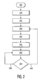
- FIG. 2 is a flowchart of a method of the present invention.
- positioning a monitor or other screen using the system of the present invention comprises seven main steps.
- the process starts at 200.
- a maximum window of allowable positions (which may include intermediate positions during motion), of the controlling joints that place the monitor are defined 201.
- This window is sometimes called a work envelope or configuration space.
- the range of permissible joint angles in all combinations defines the window. They may be pre-defined, entered manually by a technician, or trained by moving the joints in combination and storing joint angles (such as from an encoder device). This calculation may include the position or limitations of the monitor or sensing device (e.g. camera), as well as any frequently anticipated machines in the local area.
- the monitor or sensing device e.g. camera
- the sensor is calibrated 202 with the location of the viewer or other user.
- the sensor data is processed using one or more algorithms to recognize and determine the coordinates of a person or object, as discussed below, to recognize a viewer and place the viewer by determining coordinates of the recognized viewer in 3-dimensional space.
- the viewer location is the position and orientation of the midpoint of the eyes.
- a distance and/or orientation offset from a location of a wearable sensor e.g. RF transponder
- the viewer location may be calculated directly from the sensor (e.g. calculation of eye position from camera image).
- the comfortable monitor distance may be defined for each user. Further, it is important that the screen not move too frequently, which may also be defined for each user or type of situation.
- the ideal viewing position for the monitor is calculated 203. For example, a location 18 inches or 45 cm from the user, positioned with the top of the screen aligned with the center of the user's eyes may be considered optimal.
- the achievable position nearest to the ideal viewing position is calculated 204.
- the screen is moved 205 to the achievable position using actuators of a controlling machine, for example, a robot.
- the robot will be limited to stay within the work envelope by the settings defined in step 201.
- the viewer location is calculated 206 and compared 207 to a repositioning criterion.
- Recalculation of the viewer location is directed 208 until the repositioning criterion is met 209.
- the criterion may be the viewer's having moved a distance ( ⁇ x, ⁇ y, ⁇ z) or rotated an angle ( ⁇ rx, ⁇ ry or ⁇ rz) greater than a calculated threshold value.
- the repositioning criterion may also depend on a minimum or maximum amount of time having passed e.g. 5 seconds.
- the ideal viewing position based on the revised viewer location is calculated 203 and the steps 204, 205, 206 and 207 are repeated to set and maintain the new achievable position.
- the following example repositioning criterion establishes whether the user has moved substantially (for this application) and the monitor was not recently moved: Assuming that the user's mid-eye position is defined by x, y, z, if ( ⁇ x 2 + ⁇ y 2 + ⁇ z 2 > 6) and (time_since_last_movement > 10 seconds) then reposition_monitor.
- the nearest point is found by tracing the eye-position through the monitor position to a location within the reachable locations.
- the trace is the minimum distance.
- the trace can be calculated by using the minimum distance in the "configuration space" of the arm and attached device, and simulated using a method, such as the path planning disclosed in U.S. patent no. 5,808,887 , Animation of Path Planning, L. Dorst and K. Trovato.
- a gesture recognition system which locates face features in image frames is known from, for example, an article by J.B. Bishop et al. in "Automatic Head and Face Gesture Recognition,” Technical Report no. FUTH TR001, published September 1, 2001 by Future of Technology and Health, LC, Iowa City, Iowa .
- a 3-D Face Recognition approach that is able to recognize faces in video sequences independent of face pose is disclosed by V. Krüger et al. in "Appearance-based 3-D Face Recognition from Video,” University of Maryland Center for Automation Research, College Park, Maryland and The Robotics Institute, Carnegie Mellon University, Pittsburgh, Pennsylvania .
- face recognition approach is a commercial product of Seeing Machines, Inc. of Australia called “faceLABTM V 1.1.” This product can not only track head position, but also eye gaze, blinks and other, more subtle, behaviors.
- These methods can identify and provide an approximate location of an area of interest, including position and/or orientation of a pre-defined object such as a reflector, or even a person's face.
- stereoscopic and other techniques to determine the distance of an object from the camera. These methods typically analyze image geometry from views from two cameras. Image data from a single camera may be used. For example, Daphna Weinshall, Mi-Suen Lee, Tomas Brodsky, Miroslav Trajkovic and Doron Feldman, in an article entitled, "New View Generation with a Bi-centric Camera", Proceedings: 7th European Conference of Computer Vision, Copenhagen, May 2002 , have proposed methods to extract 3D information from 2D video gathered from a single, uncalibrated camera.
- Tuttle in U.S. Pat. No 5,914,671 describes a system for locating an individual where a portable wireless transponder device is worn.
- Other radio (RF) techniques can be used to identify the position and orientation of a person or other object.
- Components which can compute the position and orientation of a small receiver as it moves through space are commercially available.
- a system comprising a power supply, receiver, transmitter and hardware and software to generate and sense magnetic fields and compute position and orientation and interface with a host computer, is, for example, available under the name ISOTRAK II from Polhemus, Inc. of Colchester, Vermont. That system tracks six degrees of freedom in the movement of an object.
- the devices to be positioned are not limited to video monitors, other display screens and protective shields.
- the device may be a "cooperating device” that follows the movements of a user during a task, for example, a camera maintained in position with respect to a surgeon's hands or with respect to an instrument during surgery.
- the present invention may also, for instance, dynamically move speakers with respect to a listener's ears, or a keyboard with respect to the hands, or phone cradle and keys to match the height of a user.
- the sensor may indicate that no user has been working with the system for N (e.g. 30) minutes, so that the device moves to a more neutral position, one more readily configured for the next user, or to a "rest" position out of the way of people who may be in the area.
- N e.g. 30
- the user has the ability to remove areas from the configuration space for the arm and device movement.
- a cautionary note or symbol e.g., a flashing border or notice on a display screen, may be displayed if the arm and device are in certain areas of the configuration space.
- the processor may also monitor the user's position with respect to an object and provide an indication, warning notice or alarm if a user's position has changed in a way that might cause a display to confuse a user, in particular, if the user moves so that the orientation of the image displayed would appear to change.
Abstract
Description
- The present invention relates to an apparatus and method for positioning a device, such as a display screen.
- Many devices, such as video monitors, instrument panels, protective barriers and display screens and other displays, are used in applications in which they must be kept in sight or remain conveniently accessible to a user. These devices may be used alone or as components of complex systems, such as medical imaging systems or machine tools. The user must often change position within a prescribed area while needing to keep the screen or other device in view.
- Video monitors, in particular, often swivel or are located on stands which swivel or pivot or may be moved to a position using a scissor, yoke or other style support. A problem is that the user or other person must, typically, physically move the monitor or monitors. There may be a risk of repetitive stress injury (RSI) if the motion is frequent or the monitor or assembly containing one or more monitors, is heavy. There is, in any case, a considerable loss of efficiency.
- Manual positioning and repositioning of monitors or other devices at an optimal position requires time, which the user may not have, or which may disrupt the activity underway. Not only may the inconvenience be considerable, but the risk to an operator, patient or others may be significant if, for example, both hands are required to position a screen, or if the operator must be in an inconvenient position or must divert his or her attention from other work, to move a video monitor or other device.
- Thus, in many cases, a user's having to continually adjust the position of a device while using it, is not only inconvenient and inefficient, but can also pose a risk of injury to the user and others. Medical systems must often be operated using both hands. As the operator moves, the monitor or other device does not. Straining for an improved view may cause RSI, but may also increase the time required for a medical procedure.
- Work related injuries could be reduced by the use of automated positioning of monitors. Clinical ultrasound, in particular, has ergonomic deficiencies. As many as 80% of sonographers report RSI's causing absence sometime during their careers. About 28% leave the practice due to RSI's. This not only is an immense human toll, but it further stresses the limited supply of sonographers so that longer hours and fewer breaks are often reported. The Society of Diagnostic Medical Sonography suggests "Ergonomically Designed Ultrasound Equipment," including an external monitor.
- Current systems for automatic positioning have limited capabilities, particularly as to limitations on how the device is supported, range of movement and ability to adjust position and take obstacles into account, and are not very effective in addressing these problems. For example, two U.S. patents disclose systems providing limited tracking of a user and video monitors with limited movement.
U.S. Patent no. 6,348,928 to Jeong discloses a system in which a visual display unit is capable of automatically rotating a display screen rightward or leftward following the viewer by detecting body temperature.U.S. Patent no. 6,311,141 to Hazra discloses a method and apparatus used with a display in which a physical relationship between the display and the viewer is determined and monitored and the display is rotated or moved on a table top to maintain the physical relationship. - One challenge to such systems is that the ideal position for the monitor or other device is often unobtainable, because of obstacles or other inherent limitations on the field of movement or view.
-
WO 02/071315 - It is, therefore, one object of the present invention to provide an apparatus and method of moving, without human effort or attention, a screen or other device to a desired, predetermined position.
- Another object of the invention is to provide an apparatus and method of changing the desired position of a screen or other device as a user of the screen or other device moves.
- These and still further objects of the present invention will become apparent upon considering the following detailed description for the present invention.
- Accordingly, an apparatus and a method for automated positioning of a device according to the independent claims is provided.
- In accordance with the invention, an achievable position nearest to an optimal position for use of a device is calculated, and, without effort or attention by a user, the device is positioned accordingly. Improved efficiency and ergonomics are provided because, among other reasons, user interaction is not required.
- These objects are accomplished in one aspect of the invention by providing an apparatus comprising a sensor, which detects the presence and position of a subject, typically a user of a system, and transmits that information to a processor operatively connected to an arm assembly. The apparatus tracks the position of the user, particularly his or her face and/or eye locations so that the screen is automatically positioned to allow the user an optimal view. The screen position can be updated at time intervals or by defining a boundary of motion before an update occurs.
- The sensor is typically a camera performing imaging using visible light. Infrared cameras, among other alternatives, can be used for the sensor, although the specific markers of additional heat can more readily identify two alternative users at a distance. The sensor may also be a transmitter which detects and relays information about the location and orientation of the user, by means of, for example, a array of electromagnetic coils. Multiple sensors may be used.
- Data from the sensor is input to a processor subsystem which identifies the user's location and determines an optimal position and orientation for the device. The processor subsystem may be in a distributed computing environment.
- The processor is a computer or computers, which calculates a location of the screen and the path the arm assembly will follow to move the screen to that location. This calculation is based on the capabilities of the actuators of the controlling machine of the arm assembly, size of the monitor and nearby forbidden regions such as walls, patient location, etc.
- The mathematics of inverse kinematics can be used to find a vector of joint position variables satisfying the constraints of a given kinematic model of a mechanism and a set of position constraints on selected bodies making up that mechanism.
- Typically, in moving to an achievable position nearest an optimal position, the apparatus will simply position the device at a "joint limit." In a more complex system, if, for example, the person's face is turned, then the system may compute position by first determining the position in
space 2,54 CM*N or N inches (e.g. let N=18) from the center-of-eye position. The orientation of the eyes is next calculated. If the head is tipped, the eye-angle may be recorded. This defines the optimal location and orientation of the center of the device as well as the direction the device is to be facing. This optimal location (end-point) can be used as input directly to some robotic systems, or the inverse kinematics may be computed. - The arm assembly is a unit capable of structurally supporting and positioning a device in 3-dimensional space with 3-6 degrees of freedom. The device is connected to an end of the arm assembly. The arm assembly may be supported from a single point, such as a pole, footing or wall plate, and the arm assembly.
- The arm assembly can comprise and be positioned using a controlling machine of, for example, motors such as servo or stepper motors. Commonly, these machines are positioned either by directing individual motor "setpoints," or by providing a location for an end effector, whereby the joint values are computed using inverse kinematics. Motors may be revolute or prismatic, which rotate about an axis, or linearly along an axis.
- Degrees of freedom are independent parameters needed to specify a position of a body in a space. For example, the position in space of a hinged door can be set by one parameter, an opening angle. A hinged door thus has one degree of freedom. The position of a lawn mower operating on a flat patch of grass can be set by x- and y- position coordinates relative to x- and y- axes which are perpendicular to each other. A lawn mower on a flat surface thus has two degrees of freedom. The position and orientation of an object in three dimensional space can be set by specifying six degrees of freedom, three position coordinates and three orientation angles.
- Robotic units capable of locating a device by specifying two to six degrees of freedom are commercially available and may advantageously be used as the arm assembly. Techniques for control and coordination of electro-mechanical machinery having multiple, interacting degrees of freedom are well known. For example, an arm manufactured by Unimation, Inc. under the tradename PUMA 560 can position an object in space at a location specified by six degrees of freedom.
- The arm assembly may also have the ability to position a device with redundant degrees of freedom, i.e. degrees of freedom in excess of six, even though only six are necessary parameters for fixing the position and orientation of the device.
- In one embodiment, the present invention is a system, which tracks the position of a user, particularly his or her face, neck and/or eye locations so that a screen automatically positions itself so that it is in front of a user, but giving the user the best possible view of a person or object, through the screen. The screen can be positioned to prevent, for example, the scatter of material such as blood or other fluids from a surgical procedure from reaching the operator. The screen may be a lens and thyroid protector, i.e. a plate of lead glass or other material, which absorbs radiation generated by a diagnostic or interventional x-ray procedure before it reaches the user. The screen position can be updated every N seconds, or by defining a boundary of motion before an update occurs.
- An infrared or other proximity detector may be provided to detect an obstacle (such as another piece of equipment) or second person, in addition to the user, present near the arm or device. The detector can be interfaced with the controlling machine to prevent movement of the arm and device while the obstacle or second person is nearby.
- These and other aspects of the invention will be apparent from and elucidated with reference to the embodiment(s) described hereinafter.
- In the drawings:
-
FIG.1 1 shows an embodiment of a monitor stand according to the invention. -
FIG. 2 is a flowchart of a method of positioning the screen of the present invention. -
FIG.1 shows amonitor stand 1 embodying the present invention. Amonitor 2 is mounted on an arm assembly (here, a vertical arm) 3. The arm assembly 3 is supported on a column 4. Asensor 5 on themonitor 2 receives an image 6 of a user 7 and transmits the image data to aprocessor 10. - The
sensor 5 may be a camera, which is integrated into a monitor. The image 6 is detected, and face identified by theprocessor 10. Themonitor 2 has rotating motors or height-adjusting motors. A nominal distance such as 4,572 CM or 18 inches (about 0.5 meters) is often preferred for comfortable reading. The monitor is ideally positioned so that the user's eyes are centered relative to the screen. If the height is not adjustable, or the height is at the maximum, then the screen may be angled up or down to improve visibility. This then assumes that the monitor has additional degree of freedom. - In this simple example, the
monitor 2 in a multi-user workspace may self-adjust to height only. Thesensor 5 detects that the next person is, for example 198 CM (6'6") and theprocessor 10 determines that the ideal height adjustment 8 is to be 30,48 CM (1 foot) higher than the neutral position. It may, however, be that the possible range of motion is only 20,32 CM (+8 inches). In that case, the monitor will extend by 20,32 CM 8 inches, the nearest achievable position. - In a simple example, coordinates for predetermined positions may be stored. The recognition of the user can then simply set the device position at the location and orientation of the nearest predetermined position. In this case, no adaptive positioning occurs.
- The
monitor 2 may also have a greater range of motion in 3-dimensional space. In another case, themonitor 2 may even be 'held toward' the user, but back off as the user nears, allowing complete hands free operation of the screen. The optimal viewing pose for the monitor may comprise distance and orientation (typically 'straight ahead', zero degrees, 0.5 meters). Range of motion must be tested to ensure that the monitor has a limited range of motion, not affecting the workspace. - Although the
sensor 5 is shown as a camera embedded in a monitor, this is not a requirement. The location of the sensor is also irrelevant as long as its performance is not disturbed by the monitor or other surrounding objects. For example, an RF transponder, as the sensor has different location requirements (e.g. sensitivity to radiofrequency interference or RFI) than a camera requiring line-of-sight. -
FIG. 2 is a flowchart of a method of the present invention. In the embodiment ofFIG. 2 , positioning a monitor or other screen using the system of the present invention comprises seven main steps. The process starts at 200. A maximum window of allowable positions (which may include intermediate positions during motion), of the controlling joints that place the monitor are defined 201. This window is sometimes called a work envelope or configuration space. The range of permissible joint angles in all combinations defines the window. They may be pre-defined, entered manually by a technician, or trained by moving the joints in combination and storing joint angles (such as from an encoder device). This calculation may include the position or limitations of the monitor or sensing device (e.g. camera), as well as any frequently anticipated machines in the local area. - The sensor is calibrated 202 with the location of the viewer or other user. In calibrating the sensor, the sensor data is processed using one or more algorithms to recognize and determine the coordinates of a person or object, as discussed below, to recognize a viewer and place the viewer by determining coordinates of the recognized viewer in 3-dimensional space. Ideally, for many embodiments of the invention, the viewer location is the position and orientation of the midpoint of the eyes. A distance and/or orientation offset from a location of a wearable sensor (e.g. RF transponder) may be used, or the viewer location may be calculated directly from the sensor (e.g. calculation of eye position from camera image).
- For applications such as medical imaging systems, the comfortable monitor distance may be defined for each user. Further, it is important that the screen not move too frequently, which may also be defined for each user or type of situation.
- The ideal viewing position for the monitor is calculated 203. For example, a location 18 inches or 45 cm from the user, positioned with the top of the screen aligned with the center of the user's eyes may be considered optimal.
- The achievable position nearest to the ideal viewing position is calculated 204.
- The screen is moved 205 to the achievable position using actuators of a controlling machine, for example, a robot. The robot will be limited to stay within the work envelope by the settings defined in
step 201. - The viewer location is calculated 206 and compared 207 to a repositioning criterion. Recalculation of the viewer location is directed 208 until the repositioning criterion is met 209. For example; the criterion may be the viewer's having moved a distance (Δx, Δy, Δz) or rotated an angle (Δrx, Δry or Δrz) greater than a calculated threshold value. The repositioning criterion may also depend on a minimum or maximum amount of time having passed e.g. 5 seconds.
- If the repositioning criterion is met 209, the ideal viewing position based on the revised viewer location is calculated 203 and the
steps - If the location is outside the "reach" of the monitor, then the nearest point is found by tracing the eye-position through the monitor position to a location within the reachable locations. Ideally, the trace is the minimum distance. For multiple joint angles, the trace can be calculated by using the minimum distance in the "configuration space" of the arm and attached device, and simulated using a method, such as the path planning disclosed in
U.S. patent no. 5,808,887 , Animation of Path Planning, L. Dorst and K. Trovato. - Vision systems have been used to track objects. The cameras needed are currently inexpensive. There are many algorithms and techniques used to track objects from video sequences. For example, a detection and tracking module which extracts moving objects trajectories from a video stream is disclosed by G. Medioni et al., "Event Detection and Analysis from Video Streams," published by the University of Southern California Institute for Robotics and Intelligent Systems.
- A gesture recognition system which locates face features in image frames is known from, for example, an article by J.B. Bishop et al. in "Automatic Head and Face Gesture Recognition," Technical Report no. FUTH TR001, published September 1, 2001 by Future of Technology and Health, LC, Iowa City, Iowa. A 3-D Face Recognition approach that is able to recognize faces in video sequences independent of face pose is disclosed by V. Krüger et al. in "Appearance-based 3-D Face Recognition from Video," University of Maryland Center for Automation Research, College Park, Maryland and The Robotics Institute, Carnegie Mellon University, Pittsburgh, Pennsylvania.
- Yet another 3-D face recognition approach is a commercial product of Seeing Machines, Inc. of Canberra, Australia called "faceLAB™ V 1.1." This product can not only track head position, but also eye gaze, blinks and other, more subtle, behaviors.
- A survey paper entitled "Object Detection and Tracking in Video", dated November, 2001, by Zhong Guo of the Department of Computer Science, Kent State University lists a number of approaches used for object detection and tracking, including deformable template matching and region based approaches to object tracking using motion information.
- These methods can identify and provide an approximate location of an area of interest, including position and/or orientation of a pre-defined object such as a reflector, or even a person's face. There are also well-known stereoscopic and other techniques to determine the distance of an object from the camera. These methods typically analyze image geometry from views from two cameras. Image data from a single camera may be used. For example, Daphna Weinshall, Mi-Suen Lee, Tomas Brodsky, Miroslav Trajkovic and Doron Feldman, in an article entitled, "New View Generation with a Bi-centric Camera", Proceedings: 7th European Conference of Computer Vision, Copenhagen, May 2002, have proposed methods to extract 3D information from 2D video gathered from a single, uncalibrated camera.
- Using only position (and not orientation), Tuttle in
U.S. Pat. No 5,914,671 describes a system for locating an individual where a portable wireless transponder device is worn. Other radio (RF) techniques can be used to identify the position and orientation of a person or other object. Components which can compute the position and orientation of a small receiver as it moves through space, are commercially available. A system comprising a power supply, receiver, transmitter and hardware and software to generate and sense magnetic fields and compute position and orientation and interface with a host computer, is, for example, available under the name ISOTRAK II from Polhemus, Inc. of Colchester, Vermont. That system tracks six degrees of freedom in the movement of an object. - There are numerous ways, in addition to those mentioned above, to detect the location of an object. From that information, an estimate of the relative location of the person's eye midpoint may be calculated.
- The devices to be positioned are not limited to video monitors, other display screens and protective shields.
- The device may be a "cooperating device" that follows the movements of a user during a task, for example, a camera maintained in position with respect to a surgeon's hands or with respect to an instrument during surgery. The present invention may also, for instance, dynamically move speakers with respect to a listener's ears, or a keyboard with respect to the hands, or phone cradle and keys to match the height of a user.
- The sensor may indicate that no user has been working with the system for N (e.g. 30) minutes, so that the device moves to a more neutral position, one more readily configured for the next user, or to a "rest" position out of the way of people who may be in the area.
- The user has the ability to remove areas from the configuration space for the arm and device movement.
- A cautionary note or symbol, e.g., a flashing border or notice on a display screen, may be displayed if the arm and device are in certain areas of the configuration space.
- The processor may also monitor the user's position with respect to an object and provide an indication, warning notice or alarm if a user's position has changed in a way that might cause a display to confuse a user, in particular, if the user moves so that the orientation of the image displayed would appear to change.
- "Comprising" does not exclude other elements or steps. "A" or "an" does not exclude a plurality. A single processor or other unit may fulfill the functions of several means recited in the claims.
Claims (22)
- An apparatus (1) comprising:a device (2);an arm assembly (3) having a first end connected to a fixed support (4) and a second end connected to the device (2), said arm assembly (3) having actuating means for positioning the device;wherein the arm assembly (3) is adapted for structurally supporting and positioning the device (2) in 3-dimensional space with 3-6 degrees of freedom;a sensor (5) adapted to detect and provide information(6) about a subject (7) within a sensing range of the sensor (5);a processor (10) to process said information (6), the processor (10) being configured to determine a location of the subject (7), determine a first location for the device and control the actuating means to move the arm assembly to position the device at a second location proximate to the first location, which second location is an achievable position of the arm assembly; anda detector adapted for detecting an obstacle or a further person, said further person not being the subject,wherein the movement of the arm assembly is prevented when said obstacle or further person is detected.
- The apparatus of claim 1, wherein the first location and the second location are the same.
- The apparatus of claim 1, wherein the processor (10) determines a path of the movement of the arm assembly to the second location using inverse kinematics.
- The apparatus of claim 1, wherein the processor (10) determines a path of the movement of the arm assembly to the second location using path planning.
- The apparatus of claim 1, wherein the processor (10) determines the second location using inverse kinematics.
- The apparatus of claim 1, wherein the fixed support (4) is a single point.
- The apparatus of claim 6, wherein the fixed support (4) is a pole.
- The apparatus of claim 1, wherein the device (2) is a screen.
- The apparatus of claim 8, wherein the screen is a shield.
- The apparatus of claim 9, wherein the shield is a lens and thyroid protector.
- The apparatus of claim 8, wherein the screen is a display screen.
- The apparatus of claim 11, wherein the display screen is a video monitor.
- The apparatus of claim 1, wherein the second location is chosen from two or more predetermined positions.
- The apparatus of claim 1, wherein the processor (10) causes the actuating means of the arm assembly (3) to move the device to a rest position if the subject is not detected.
- The apparatus of claim 1 further comprising a second sensor, the second sensor being configured to detect the presence of a person who is not the subject and being operatively coupled to the arm assembly (3) to prevent movement of the arm and the device if any said person who is not the subject is detected.
- The apparatus of claim 1 wherein the first location is determined based on optimal viewing of the device.
- The apparatus of claim 1 wherein the first location is determined based on optimal use of the device by the subject.
- The apparatus of claim 1 wherein the first location is determined based on optimal viewing by the subject through the device.
- The apparatus of claim 1 wherein the positions of the subject and device are monitored with respect to each other and a warning is displayed on a screen if certain changes in said positions are detected.
- The apparatus of claim 1 wherein the positions of the subject and device are monitored with respect to each other and an alarm is activated if certain changes in said positions are detected.
- A method for positioning a device comprising:(a) calculating a window of allowable positions (201) ;(b) calibrating a sensor with respect to a first user location (202) detecting and providing information (6) about a subject (7) within a sensing range of the sensor for(c) calculating an ideal position (203) of the device based upon the first user location;(d) calculating an achievable position within said window nearest the ideal position (204);(e) moving the device within the window of allowable positions to the achievable position (205); and(f) detecting an obstacle or a further person, said further person not being the subject; and(g) preventing the movement of the arm assembly in case said obstacle or further person is detected.
- The method of claim 21 further comprising: calculating (206) a second user location from sensor data collected after the first user location was determined; comparing the second user location with a repositioning criterion; repeating the step of calculating (206) a second user location from sensor data collected after the first user location was determined and comparing the second user location with the repositioning criterion, until the repositioning criterion is met (209); and repeating steps (c) and (d) of claim 21 to calculate a second ideal position of the device based on the second user location and a second achievable position; and moving the device within the window of allowable positions to the second achievable position (205).
Applications Claiming Priority (3)
| Application Number | Priority Date | Filing Date | Title |
|---|---|---|---|
| US43145202P | 2002-12-06 | 2002-12-06 | |
| US431452P | 2002-12-06 | ||
| PCT/IB2003/005428 WO2004052225A2 (en) | 2002-12-06 | 2003-11-24 | Apparatus and method for automated positioning of a device |
Publications (2)
| Publication Number | Publication Date |
|---|---|
| EP1578290A2 EP1578290A2 (en) | 2005-09-28 |
| EP1578290B1 true EP1578290B1 (en) | 2012-03-28 |
Family
ID=32507730
Family Applications (1)
| Application Number | Title | Priority Date | Filing Date |
|---|---|---|---|
| EP03777029A Expired - Lifetime EP1578290B1 (en) | 2002-12-06 | 2003-11-24 | Apparatus and method for automated positioning of a device |
Country Status (7)
| Country | Link |
|---|---|
| US (1) | US20060071135A1 (en) |
| EP (1) | EP1578290B1 (en) |
| JP (1) | JP2006509256A (en) |
| CN (1) | CN100413478C (en) |
| AT (1) | ATE551014T1 (en) |
| AU (1) | AU2003286286A1 (en) |
| WO (1) | WO2004052225A2 (en) |
Cited By (1)
| Publication number | Priority date | Publication date | Assignee | Title |
|---|---|---|---|---|
| US9782069B2 (en) | 2014-11-06 | 2017-10-10 | International Business Machines Corporation | Correcting systematic calibration errors in eye tracking data |
Families Citing this family (53)
| Publication number | Priority date | Publication date | Assignee | Title |
|---|---|---|---|---|
| US20030064784A1 (en) * | 2001-09-28 | 2003-04-03 | William Wells | Wide screen gaming apparatus |
| US9030532B2 (en) * | 2004-08-19 | 2015-05-12 | Microsoft Technology Licensing, Llc | Stereoscopic image display |
| DE102004042489B4 (en) | 2004-08-31 | 2012-03-29 | Siemens Ag | Medical examination or treatment facility with associated method |
| KR100681233B1 (en) * | 2004-10-28 | 2007-02-09 | 김재황 | Monitering apparatus for laparoscopice surgery and disply method thereof |
| US7835498B2 (en) | 2005-02-18 | 2010-11-16 | Koninklijke Philips Electronics N. V. | Automatic control of a medical device |
| DE102005045362B4 (en) | 2005-09-22 | 2012-03-22 | Siemens Ag | Device for determining the position of a medical instrument, associated imaging examination device and associated method |
| DE102006011233B4 (en) | 2006-03-10 | 2011-04-28 | Siemens Ag | Method and device for optimizing the image representation on an imaging device |
| EP1929976A1 (en) * | 2006-12-07 | 2008-06-11 | Swiss Medical Technology GmbH | Support system and method for viewer-dependent positioning and alignment of a display unit |
| US8031272B2 (en) * | 2007-07-19 | 2011-10-04 | International Business Machines Corporation | System and method of adjusting viewing angle for display |
| US8115877B2 (en) * | 2008-01-04 | 2012-02-14 | International Business Machines Corporation | System and method of adjusting viewing angle for display based on viewer positions and lighting conditions |
| JP2012501592A (en) * | 2008-09-01 | 2012-01-19 | ミツビシ エレクトリック ビジュアル ソリューションズ アメリカ, インコーポレイテッド | System and method for improving television viewing |
| CN101714313A (en) * | 2008-10-08 | 2010-05-26 | 鸿富锦精密工业(深圳)有限公司 | Display |
| US20100169792A1 (en) * | 2008-12-29 | 2010-07-01 | Seif Ascar | Web and visual content interaction analytics |
| US8199186B2 (en) | 2009-03-05 | 2012-06-12 | Microsoft Corporation | Three-dimensional (3D) imaging based on motionparallax |
| US20120116257A1 (en) * | 2009-03-05 | 2012-05-10 | Searete Llc | Postural information system and method including determining response to subject advisory information |
| KR100955480B1 (en) * | 2009-03-12 | 2010-04-30 | 삼성전자주식회사 | Supporting device for display unit and display unit having the same |
| US20100295782A1 (en) * | 2009-05-21 | 2010-11-25 | Yehuda Binder | System and method for control based on face ore hand gesture detection |
| CN101938614A (en) * | 2009-06-30 | 2011-01-05 | 青岛海信电器股份有限公司 | Display device and automatic sheering method thereof |
| WO2011003437A1 (en) * | 2009-07-06 | 2011-01-13 | Siemens Aktiengesellschaft | Visualization system for correct alignment of an output unit with respect to a user and method for this purpose |
| KR101088083B1 (en) * | 2009-08-11 | 2011-11-30 | 송세경 | Intelligent display apparutus having publicity function and method of performing publicity function |
| TW201123032A (en) * | 2009-12-30 | 2011-07-01 | Hon Hai Prec Ind Co Ltd | Monitor adjusting system and the method use the same |
| FR2960938B1 (en) * | 2010-06-02 | 2012-06-15 | Univ Paris Curie | SCREEN SUPPORT |
| EP4026508B1 (en) | 2010-06-28 | 2023-10-18 | Brainlab AG | Generating images for at least two displays in image-guided surgery |
| TW201205469A (en) * | 2010-07-23 | 2012-02-01 | Hon Hai Prec Ind Co Ltd | Display device and method for adjusting display orientation thereof |
| US8730332B2 (en) | 2010-09-29 | 2014-05-20 | Digitaloptics Corporation | Systems and methods for ergonomic measurement |
| US8913005B2 (en) | 2011-04-08 | 2014-12-16 | Fotonation Limited | Methods and systems for ergonomic feedback using an image analysis module |
| US9020615B2 (en) | 2011-12-06 | 2015-04-28 | Microsoft Technology Licensing, Llc | Stability control system |
| US9035742B2 (en) | 2011-12-06 | 2015-05-19 | Microsoft Technology Licensing, Llc | Electronic compensated pivot control |
| FR2983939B1 (en) * | 2011-12-08 | 2016-11-25 | Archos | MOTORIZED SUPPORT FOR TOUCH SHELF |
| EP2802894B1 (en) * | 2012-01-12 | 2018-03-28 | Brainlab AG | Method and system for medical tracking using a plurality of camera positions |
| KR101983248B1 (en) * | 2012-06-13 | 2019-05-29 | 삼성디스플레이 주식회사 | Method of driving a display panel, display panel driving apparatus for performing the method and display apparatus having the display panel driving apparatus |
| JP5941762B2 (en) * | 2012-06-14 | 2016-06-29 | オリンパス株式会社 | Manipulator system |
| JP6252004B2 (en) | 2013-07-16 | 2017-12-27 | セイコーエプソン株式会社 | Information processing apparatus, information processing method, and information processing system |
| TWI752618B (en) | 2013-10-22 | 2022-01-11 | 日商半導體能源研究所股份有限公司 | Secondary battery and electronic device |
| CN104679397A (en) * | 2013-11-29 | 2015-06-03 | 英业达科技有限公司 | Display and control method thereof |
| US9452531B2 (en) * | 2014-02-04 | 2016-09-27 | Microsoft Technology Licensing, Llc | Controlling a robot in the presence of a moving object |
| EP3110305B1 (en) | 2014-02-27 | 2021-09-01 | University Surgical Associates, Inc. | Interactive display for surgery |
| EP3025666B1 (en) * | 2014-11-26 | 2017-11-01 | MASMEC S.p.A. | Computer-assisted system for guiding a surgical/diagnostic instrument in the body of a patient |
| DE102015218926A1 (en) | 2015-09-30 | 2017-03-30 | Carl Zeiss Meditec Ag | Method for controlling a surgical microscope system |
| FR3048934B1 (en) * | 2016-03-18 | 2018-04-13 | Faurecia Interieur Industrie | DEVICE FOR CONTROLLING A FUNCTION OF A VEHICLE COMPRISING A MOBILE CONTROL DEVICE |
| US20180080598A1 (en) * | 2016-09-20 | 2018-03-22 | Apple Inc. | Counterbalanced display stand |
| US10623724B2 (en) | 2017-07-19 | 2020-04-14 | International Business Machines Corporation | Adaptive display environment for dynamic applications |
| US10464209B2 (en) * | 2017-10-05 | 2019-11-05 | Auris Health, Inc. | Robotic system with indication of boundary for robotic arm |
| CN107669340A (en) * | 2017-10-28 | 2018-02-09 | 深圳市前海安测信息技术有限公司 | 3D image surgical navigational robots and its control method |
| DE102018200108A1 (en) * | 2018-01-05 | 2019-07-11 | Siemens Healthcare Gmbh | Positioning of an examination object with respect to an X-ray device |
| US11607200B2 (en) | 2019-08-13 | 2023-03-21 | GE Precision Healthcare LLC | Methods and system for camera-aided ultrasound scan setup and control |
| WO2021134160A1 (en) * | 2019-12-30 | 2021-07-08 | Fresenius Medical Care Deutschland Gmbh | Method for driving a display, tracking monitor and storage medium |
| US20210232820A1 (en) * | 2020-01-24 | 2021-07-29 | Position Imaging, Inc. | Kiosk with object identification, registration, and tracking capabilities with light and/or audio guidance |
| CN112283514A (en) * | 2020-10-20 | 2021-01-29 | 雷彦刚 | Mounting rack for placing medical equipment and control method thereof |
| JP2022088930A (en) * | 2020-12-03 | 2022-06-15 | 株式会社吉田製作所 | Dental examination system |
| JP2022091291A (en) * | 2020-12-09 | 2022-06-21 | 富士フイルムヘルスケア株式会社 | Ultrasonic diagnostic apparatus |
| CN113662494B (en) * | 2021-08-17 | 2023-12-26 | 岱川医疗(深圳)有限责任公司 | Endoscope workstation, control method thereof, control device thereof, and storage medium |
| WO2023069745A1 (en) * | 2021-10-22 | 2023-04-27 | Intuitive Surgical Operations, Inc. | Controlling a repositionable structure system based on a geometric relationship between an operator and a computer-assisted device |
Family Cites Families (11)
| Publication number | Priority date | Publication date | Assignee | Title |
|---|---|---|---|---|
| FR2606915A1 (en) * | 1986-11-17 | 1988-05-20 | Tournay Omer | AUTOMATIC CONTROL OF ORIENTATION OF SCIALYTIC LAMPS |
| US5808887A (en) * | 1987-11-20 | 1998-09-15 | Philips Electronics North America Corporation | Animation of path planning |
| KR940007012Y1 (en) * | 1991-01-31 | 1994-10-07 | 삼성전자 주식회사 | Tilting device |
| CN2118507U (en) * | 1992-03-17 | 1992-10-14 | 陈维良 | Moveable pretective screem for dentistry |
| US5520888A (en) * | 1994-02-01 | 1996-05-28 | Safe Alternatives Corporation | Bio-medical waste reactor, sterilizer and methods thereof |
| US5914671A (en) * | 1997-02-27 | 1999-06-22 | Micron Communications, Inc. | System and method for locating individuals and equipment, airline reservation system, communication system |
| US6181983B1 (en) * | 1997-06-20 | 2001-01-30 | Deutsches Zentrum f{umlaut over (u)}r Luft-und Raumfahrt e.v. | Method of command control for a robot manipulator |
| DE19736995B4 (en) * | 1997-08-26 | 2009-05-07 | Fraunhofer-Gesellschaft zur Förderung der angewandten Forschung e.V. | Device for determining a fixation point |
| US6311141B1 (en) * | 1998-07-02 | 2001-10-30 | Intel Corporation | Controlling a physical Relationship between a display and a viewer of the display |
| KR100312486B1 (en) * | 1998-11-13 | 2002-02-28 | 구자홍 | Automatic rotating device of video display device and its rotation method |
| US6931596B2 (en) * | 2001-03-05 | 2005-08-16 | Koninklijke Philips Electronics N.V. | Automatic positioning of display depending upon the viewer's location |
-
2003
- 2003-11-24 CN CNB2003801049867A patent/CN100413478C/en not_active Expired - Fee Related
- 2003-11-24 US US10/537,135 patent/US20060071135A1/en not_active Abandoned
- 2003-11-24 AT AT03777029T patent/ATE551014T1/en active
- 2003-11-24 JP JP2004558909A patent/JP2006509256A/en active Pending
- 2003-11-24 EP EP03777029A patent/EP1578290B1/en not_active Expired - Lifetime
- 2003-11-24 WO PCT/IB2003/005428 patent/WO2004052225A2/en active Application Filing
- 2003-11-24 AU AU2003286286A patent/AU2003286286A1/en not_active Abandoned
Cited By (1)
| Publication number | Priority date | Publication date | Assignee | Title |
|---|---|---|---|---|
| US9782069B2 (en) | 2014-11-06 | 2017-10-10 | International Business Machines Corporation | Correcting systematic calibration errors in eye tracking data |
Also Published As
| Publication number | Publication date |
|---|---|
| US20060071135A1 (en) | 2006-04-06 |
| EP1578290A2 (en) | 2005-09-28 |
| JP2006509256A (en) | 2006-03-16 |
| CN100413478C (en) | 2008-08-27 |
| ATE551014T1 (en) | 2012-04-15 |
| WO2004052225A2 (en) | 2004-06-24 |
| AU2003286286A1 (en) | 2004-06-30 |
| WO2004052225A3 (en) | 2004-09-10 |
| CN1720008A (en) | 2006-01-11 |
Similar Documents
| Publication | Publication Date | Title |
|---|---|---|
| EP1578290B1 (en) | Apparatus and method for automated positioning of a device | |
| US11754853B2 (en) | Systems and methods for three-dimensional visualization during robotic surgery | |
| US11517377B2 (en) | Systems and methods for predictively avoiding tracking interruptions involving a manipulator | |
| US20240099791A1 (en) | Roboticized Surgery System with Improved Control | |
| CN109567954B (en) | Workflow assistance system and method for image guided program | |
| US10588699B2 (en) | Intelligent positioning system and methods therefore | |
| CN110236682B (en) | System and method for recentering imaging device and input control device | |
| EP2967348B1 (en) | Intelligent positioning system | |
| EP3336848B1 (en) | Method for operating a medical imaging device and medical imaging device | |
| JP2021129984A (en) | Displaying virtual model of planned instrument attachment to ensure correct selection of physical instrument attachment | |
| CN113271884A (en) | System and method for integrating motion with an imaging device | |
| JP2021122743A (en) | Extended reality instrument interaction zone for navigated robotic surgery | |
| CN111132631A (en) | System and method for interactive point display in a teleoperational assembly | |
| WO2019083886A1 (en) | System and method for repositioning input control devices | |
| US20230302650A1 (en) | Detection and mitigation of predicted collisions of objects with user control system | |
| WO2022232170A1 (en) | Method and apparatus for providing input device repositioning reminders | |
| CN116546931A (en) | Techniques for adjusting a field of view of an imaging device based on head movement of an operator | |
| WO2023244636A1 (en) | Visual guidance for repositioning a computer-assisted system | |
| WO2024006492A1 (en) | Systems and methods for stereoscopic visualization in surgical robotics without requiring glasses or headgear | |
| WO2023069745A1 (en) | Controlling a repositionable structure system based on a geometric relationship between an operator and a computer-assisted device |
Legal Events
| Date | Code | Title | Description |
|---|---|---|---|
| PUAI | Public reference made under article 153(3) epc to a published international application that has entered the european phase |
Free format text: ORIGINAL CODE: 0009012 |
|
| 17P | Request for examination filed |
Effective date: 20050706 |
|
| AK | Designated contracting states |
Kind code of ref document: A2 Designated state(s): AT BE BG CH CY CZ DE DK EE ES FI FR GB GR HU IE IT LI LU MC NL PT RO SE SI SK TR |
|
| AX | Request for extension of the european patent |
Extension state: AL LT LV MK |
|
| DAX | Request for extension of the european patent (deleted) | ||
| 17Q | First examination report despatched |
Effective date: 20100311 |
|
| GRAP | Despatch of communication of intention to grant a patent |
Free format text: ORIGINAL CODE: EPIDOSNIGR1 |
|
| GRAS | Grant fee paid |
Free format text: ORIGINAL CODE: EPIDOSNIGR3 |
|
| GRAA | (expected) grant |
Free format text: ORIGINAL CODE: 0009210 |
|
| AK | Designated contracting states |
Kind code of ref document: B1 Designated state(s): AT BE BG CH CY CZ DE DK EE ES FI FR GB GR HU IE IT LI LU MC NL PT RO SE SI SK TR |
|
| REG | Reference to a national code |
Ref country code: GB Ref legal event code: FG4D |
|
| REG | Reference to a national code |
Ref country code: CH Ref legal event code: EP |
|
| REG | Reference to a national code |
Ref country code: AT Ref legal event code: REF Ref document number: 551014 Country of ref document: AT Kind code of ref document: T Effective date: 20120415 |
|
| REG | Reference to a national code |
Ref country code: IE Ref legal event code: FG4D |
|
| REG | Reference to a national code |
Ref country code: DE Ref legal event code: R096 Ref document number: 60340436 Country of ref document: DE Effective date: 20120516 |
|
| REG | Reference to a national code |
Ref country code: DE Ref legal event code: R084 Ref document number: 60340436 Country of ref document: DE Effective date: 20120417 |
|
| REG | Reference to a national code |
Ref country code: GB Ref legal event code: 746 Effective date: 20120525 |
|
| REG | Reference to a national code |
Ref country code: NL Ref legal event code: VDEP Effective date: 20120328 |
|
| PG25 | Lapsed in a contracting state [announced via postgrant information from national office to epo] |
Ref country code: FI Free format text: LAPSE BECAUSE OF FAILURE TO SUBMIT A TRANSLATION OF THE DESCRIPTION OR TO PAY THE FEE WITHIN THE PRESCRIBED TIME-LIMIT Effective date: 20120328 Ref country code: GR Free format text: LAPSE BECAUSE OF FAILURE TO SUBMIT A TRANSLATION OF THE DESCRIPTION OR TO PAY THE FEE WITHIN THE PRESCRIBED TIME-LIMIT Effective date: 20120629 |
|
| REG | Reference to a national code |
Ref country code: AT Ref legal event code: MK05 Ref document number: 551014 Country of ref document: AT Kind code of ref document: T Effective date: 20120328 |
|
| PG25 | Lapsed in a contracting state [announced via postgrant information from national office to epo] |
Ref country code: CY Free format text: LAPSE BECAUSE OF FAILURE TO SUBMIT A TRANSLATION OF THE DESCRIPTION OR TO PAY THE FEE WITHIN THE PRESCRIBED TIME-LIMIT Effective date: 20120328 |
|
| PG25 | Lapsed in a contracting state [announced via postgrant information from national office to epo] |
Ref country code: CZ Free format text: LAPSE BECAUSE OF FAILURE TO SUBMIT A TRANSLATION OF THE DESCRIPTION OR TO PAY THE FEE WITHIN THE PRESCRIBED TIME-LIMIT Effective date: 20120328 Ref country code: SE Free format text: LAPSE BECAUSE OF FAILURE TO SUBMIT A TRANSLATION OF THE DESCRIPTION OR TO PAY THE FEE WITHIN THE PRESCRIBED TIME-LIMIT Effective date: 20120328 Ref country code: SI Free format text: LAPSE BECAUSE OF FAILURE TO SUBMIT A TRANSLATION OF THE DESCRIPTION OR TO PAY THE FEE WITHIN THE PRESCRIBED TIME-LIMIT Effective date: 20120328 Ref country code: BE Free format text: LAPSE BECAUSE OF FAILURE TO SUBMIT A TRANSLATION OF THE DESCRIPTION OR TO PAY THE FEE WITHIN THE PRESCRIBED TIME-LIMIT Effective date: 20120328 Ref country code: EE Free format text: LAPSE BECAUSE OF FAILURE TO SUBMIT A TRANSLATION OF THE DESCRIPTION OR TO PAY THE FEE WITHIN THE PRESCRIBED TIME-LIMIT Effective date: 20120328 Ref country code: RO Free format text: LAPSE BECAUSE OF FAILURE TO SUBMIT A TRANSLATION OF THE DESCRIPTION OR TO PAY THE FEE WITHIN THE PRESCRIBED TIME-LIMIT Effective date: 20120328 |
|
| PG25 | Lapsed in a contracting state [announced via postgrant information from national office to epo] |
Ref country code: SK Free format text: LAPSE BECAUSE OF FAILURE TO SUBMIT A TRANSLATION OF THE DESCRIPTION OR TO PAY THE FEE WITHIN THE PRESCRIBED TIME-LIMIT Effective date: 20120328 Ref country code: PT Free format text: LAPSE BECAUSE OF FAILURE TO SUBMIT A TRANSLATION OF THE DESCRIPTION OR TO PAY THE FEE WITHIN THE PRESCRIBED TIME-LIMIT Effective date: 20120730 |
|
| PG25 | Lapsed in a contracting state [announced via postgrant information from national office to epo] |
Ref country code: AT Free format text: LAPSE BECAUSE OF FAILURE TO SUBMIT A TRANSLATION OF THE DESCRIPTION OR TO PAY THE FEE WITHIN THE PRESCRIBED TIME-LIMIT Effective date: 20120328 Ref country code: DK Free format text: LAPSE BECAUSE OF FAILURE TO SUBMIT A TRANSLATION OF THE DESCRIPTION OR TO PAY THE FEE WITHIN THE PRESCRIBED TIME-LIMIT Effective date: 20120328 Ref country code: NL Free format text: LAPSE BECAUSE OF FAILURE TO SUBMIT A TRANSLATION OF THE DESCRIPTION OR TO PAY THE FEE WITHIN THE PRESCRIBED TIME-LIMIT Effective date: 20120328 |
|
| PLBE | No opposition filed within time limit |
Free format text: ORIGINAL CODE: 0009261 |
|
| STAA | Information on the status of an ep patent application or granted ep patent |
Free format text: STATUS: NO OPPOSITION FILED WITHIN TIME LIMIT |
|
| PG25 | Lapsed in a contracting state [announced via postgrant information from national office to epo] |
Ref country code: IT Free format text: LAPSE BECAUSE OF FAILURE TO SUBMIT A TRANSLATION OF THE DESCRIPTION OR TO PAY THE FEE WITHIN THE PRESCRIBED TIME-LIMIT Effective date: 20120328 |
|
| PGFP | Annual fee paid to national office [announced via postgrant information from national office to epo] |
Ref country code: GB Payment date: 20121130 Year of fee payment: 10 |
|
| 26N | No opposition filed |
Effective date: 20130103 |
|
| REG | Reference to a national code |
Ref country code: DE Ref legal event code: R097 Ref document number: 60340436 Country of ref document: DE Effective date: 20130103 |
|
| PG25 | Lapsed in a contracting state [announced via postgrant information from national office to epo] |
Ref country code: ES Free format text: LAPSE BECAUSE OF FAILURE TO SUBMIT A TRANSLATION OF THE DESCRIPTION OR TO PAY THE FEE WITHIN THE PRESCRIBED TIME-LIMIT Effective date: 20120709 |
|
| PGFP | Annual fee paid to national office [announced via postgrant information from national office to epo] |
Ref country code: DE Payment date: 20130131 Year of fee payment: 10 |
|
| REG | Reference to a national code |
Ref country code: CH Ref legal event code: PL |
|
| PG25 | Lapsed in a contracting state [announced via postgrant information from national office to epo] |
Ref country code: LI Free format text: LAPSE BECAUSE OF NON-PAYMENT OF DUE FEES Effective date: 20121130 Ref country code: BG Free format text: LAPSE BECAUSE OF FAILURE TO SUBMIT A TRANSLATION OF THE DESCRIPTION OR TO PAY THE FEE WITHIN THE PRESCRIBED TIME-LIMIT Effective date: 20120628 Ref country code: CH Free format text: LAPSE BECAUSE OF NON-PAYMENT OF DUE FEES Effective date: 20121130 |
|
| REG | Reference to a national code |
Ref country code: IE Ref legal event code: MM4A |
|
| REG | Reference to a national code |
Ref country code: FR Ref legal event code: ST Effective date: 20130731 |
|
| PG25 | Lapsed in a contracting state [announced via postgrant information from national office to epo] |
Ref country code: IE Free format text: LAPSE BECAUSE OF NON-PAYMENT OF DUE FEES Effective date: 20121124 |
|
| PG25 | Lapsed in a contracting state [announced via postgrant information from national office to epo] |
Ref country code: FR Free format text: LAPSE BECAUSE OF NON-PAYMENT OF DUE FEES Effective date: 20121130 |
|
| REG | Reference to a national code |
Ref country code: DE Ref legal event code: R082 Ref document number: 60340436 Country of ref document: DE Representative=s name: GIPP, THOMAS, DIPL.-ING., DE |
|
| PG25 | Lapsed in a contracting state [announced via postgrant information from national office to epo] |
Ref country code: TR Free format text: LAPSE BECAUSE OF FAILURE TO SUBMIT A TRANSLATION OF THE DESCRIPTION OR TO PAY THE FEE WITHIN THE PRESCRIBED TIME-LIMIT Effective date: 20120328 Ref country code: MC Free format text: LAPSE BECAUSE OF NON-PAYMENT OF DUE FEES Effective date: 20121130 |
|
| REG | Reference to a national code |
Ref country code: DE Ref legal event code: R082 Ref document number: 60340436 Country of ref document: DE Representative=s name: GIPP, THOMAS, DIPL.-ING., DE Effective date: 20140402 Ref country code: DE Ref legal event code: R081 Ref document number: 60340436 Country of ref document: DE Owner name: KONINKLIJKE PHILIPS N.V., NL Free format text: FORMER OWNER: KONINKLIJKE PHILIPS ELECTRONICS N.V., EINDHOVEN, NL Effective date: 20140402 Ref country code: DE Ref legal event code: R081 Ref document number: 60340436 Country of ref document: DE Owner name: KONINKLIJKE PHILIPS N.V., NL Free format text: FORMER OWNER: KONINKLIJKE PHILIPS ELECTRONICS N.V., EINDHOVEN, NL Effective date: 20120328 |
|
| PG25 | Lapsed in a contracting state [announced via postgrant information from national office to epo] |
Ref country code: LU Free format text: LAPSE BECAUSE OF NON-PAYMENT OF DUE FEES Effective date: 20121124 |
|
| GBPC | Gb: european patent ceased through non-payment of renewal fee |
Effective date: 20131124 |
|
| PG25 | Lapsed in a contracting state [announced via postgrant information from national office to epo] |
Ref country code: HU Free format text: LAPSE BECAUSE OF FAILURE TO SUBMIT A TRANSLATION OF THE DESCRIPTION OR TO PAY THE FEE WITHIN THE PRESCRIBED TIME-LIMIT Effective date: 20031124 |
|
| PG25 | Lapsed in a contracting state [announced via postgrant information from national office to epo] |
Ref country code: DE Free format text: LAPSE BECAUSE OF NON-PAYMENT OF DUE FEES Effective date: 20140603 |
|
| REG | Reference to a national code |
Ref country code: DE Ref legal event code: R119 Ref document number: 60340436 Country of ref document: DE Effective date: 20140603 |
|
| PG25 | Lapsed in a contracting state [announced via postgrant information from national office to epo] |
Ref country code: GB Free format text: LAPSE BECAUSE OF NON-PAYMENT OF DUE FEES Effective date: 20131124 |