JP5941762B2 - Manipulator system - Google Patents
Manipulator system Download PDFInfo
- Publication number
- JP5941762B2 JP5941762B2 JP2012134687A JP2012134687A JP5941762B2 JP 5941762 B2 JP5941762 B2 JP 5941762B2 JP 2012134687 A JP2012134687 A JP 2012134687A JP 2012134687 A JP2012134687 A JP 2012134687A JP 5941762 B2 JP5941762 B2 JP 5941762B2
- Authority
- JP
- Japan
- Prior art keywords
- unit
- angle
- function
- display
- operation unit
- Prior art date
- Legal status (The legal status is an assumption and is not a legal conclusion. Google has not performed a legal analysis and makes no representation as to the accuracy of the status listed.)
- Expired - Fee Related
Links
Images


Classifications
-
- A—HUMAN NECESSITIES
- A61—MEDICAL OR VETERINARY SCIENCE; HYGIENE
- A61B—DIAGNOSIS; SURGERY; IDENTIFICATION
- A61B34/00—Computer-aided surgery; Manipulators or robots specially adapted for use in surgery
- A61B34/30—Surgical robots
-
- A—HUMAN NECESSITIES
- A61—MEDICAL OR VETERINARY SCIENCE; HYGIENE
- A61B—DIAGNOSIS; SURGERY; IDENTIFICATION
- A61B1/00—Instruments for performing medical examinations of the interior of cavities or tubes of the body by visual or photographical inspection, e.g. endoscopes; Illuminating arrangements therefor
- A61B1/00147—Holding or positioning arrangements
- A61B1/0016—Holding or positioning arrangements using motor drive units
-
- A—HUMAN NECESSITIES
- A61—MEDICAL OR VETERINARY SCIENCE; HYGIENE
- A61B—DIAGNOSIS; SURGERY; IDENTIFICATION
- A61B1/00—Instruments for performing medical examinations of the interior of cavities or tubes of the body by visual or photographical inspection, e.g. endoscopes; Illuminating arrangements therefor
- A61B1/04—Instruments for performing medical examinations of the interior of cavities or tubes of the body by visual or photographical inspection, e.g. endoscopes; Illuminating arrangements therefor combined with photographic or television appliances
- A61B1/05—Instruments for performing medical examinations of the interior of cavities or tubes of the body by visual or photographical inspection, e.g. endoscopes; Illuminating arrangements therefor combined with photographic or television appliances characterised by the image sensor, e.g. camera, being in the distal end portion
-
- A—HUMAN NECESSITIES
- A61—MEDICAL OR VETERINARY SCIENCE; HYGIENE
- A61B—DIAGNOSIS; SURGERY; IDENTIFICATION
- A61B1/00—Instruments for performing medical examinations of the interior of cavities or tubes of the body by visual or photographical inspection, e.g. endoscopes; Illuminating arrangements therefor
- A61B1/06—Instruments for performing medical examinations of the interior of cavities or tubes of the body by visual or photographical inspection, e.g. endoscopes; Illuminating arrangements therefor with illuminating arrangements
- A61B1/0661—Endoscope light sources
- A61B1/0676—Endoscope light sources at distal tip of an endoscope
-
- G—PHYSICS
- G02—OPTICS
- G02B—OPTICAL ELEMENTS, SYSTEMS OR APPARATUS
- G02B23/00—Telescopes, e.g. binoculars; Periscopes; Instruments for viewing the inside of hollow bodies; Viewfinders; Optical aiming or sighting devices
- G02B23/24—Instruments or systems for viewing the inside of hollow bodies, e.g. fibrescopes
- G02B23/2476—Non-optical details, e.g. housings, mountings, supports
- G02B23/2484—Arrangements in relation to a camera or imaging device
Description
本発明は、マニピュレータシステムに関するものである。 The present invention relates to a manipulator system.
従来、内視鏡を移動可能に支持する支持手段によって内視鏡を移動させた場合に、該支持手段の移動量に基づいて、内視鏡画像を表示する表示部を覗き込む視線の延長線上に内視鏡先端部の光軸が配置されるように、表示部を移動させる観察装置が知られている(例えば、特許文献1参照。)。 Conventionally, when the endoscope is moved by a supporting means that movably supports the endoscope, based on the amount of movement of the supporting means, on the extension line of sight that looks into the display unit that displays the endoscope image An observation apparatus that moves the display unit so that the optical axis of the distal end portion of the endoscope is arranged on the endoscope is known (for example, see Patent Document 1).
特許文献1の観察装置によれば、術者が内視鏡を直接操作して患者の体腔内の観察位置を変更した場合でも、特別な作業をすることなく手術作業に最適な姿勢を得ることができるという効果がある。 According to the observation apparatus of Patent Document 1, even when the operator directly operates the endoscope to change the observation position in the body cavity of the patient, an optimal posture for the surgical operation can be obtained without performing a special operation. There is an effect that can be.
しかしながら、内視鏡の先端面から突出させた処置具は、術者が両手で操作ハンドルを操作することにより操作され、内視鏡の先端部に備えられた湾曲部は、通常、スイッチによって、術者が手足を大きく移動させることなく操作される。このため、湾曲部の湾曲の度合いを変化させて内視鏡の視野方向を変更すると、処置具を操作していなくても、表示部に表示される処置具の向きが変化してしまうという不都合がある。 However, the treatment tool protruded from the distal end surface of the endoscope is operated by the operator operating the operation handle with both hands, and the bending portion provided at the distal end portion of the endoscope is usually switched by a switch. The surgeon is operated without greatly moving the limbs. For this reason, when the viewing direction of the endoscope is changed by changing the degree of bending of the bending portion, the orientation of the treatment tool displayed on the display portion is changed even when the treatment tool is not operated. There is.
すなわち、湾曲部の操作前後において、処置具に同じ動作をさせる場合の操作ハンドルの移動方向は同一であるのに対し、表示部に表示される処置具の移動方向は変化するので、術者は、頭の中で、表示部内の処置具の前後左右方向がどちらであるのかを常に確認しながら操作ハンドルを操作しなければならず、直感的な操作を行うことができないという問題がある。 That is, before and after the operation of the bending portion, the movement direction of the operation handle when the treatment tool performs the same operation is the same, whereas the movement direction of the treatment tool displayed on the display portion changes, In the head, there is a problem that the operation handle must be operated while always confirming the front / rear / right / left direction of the treatment instrument in the display unit, and an intuitive operation cannot be performed.
本発明は、上述した事情に鑑みてなされたものであって、被写体の観察方向を切り替えても、表示部に表示される処置具を直感的に操作することができるマニピュレータシステムを提供することを目的としている。 The present invention has been made in view of the above-described circumstances, and provides a manipulator system capable of intuitively operating a treatment instrument displayed on a display unit even when the observation direction of a subject is switched. It is aimed.
上記目的を達成するために、本発明は以下の手段を提供する。
本発明の一態様は、被写体を処置する処置部と、前記被写体および処置部を撮影する撮影部と、該撮影部により取得された画像を表示する表示部と、該表示部を支持して移動させる表示部駆動部と、前記処置部を操作する操作部と、該操作部を支持し1て移動させる操作部駆動部と、前記表示部と前記操作部との相対位置関係を、前記処置部と前記撮影部との相対位置関係に近づけるように前記表示部駆動部および前記操作部駆動部を制御する制御部とを備えるマニピュレータシステムを提供する。
In order to achieve the above object, the present invention provides the following means.
In one embodiment of the present invention, a treatment unit that treats a subject, a photographing unit that photographs the subject and the treatment unit, a display unit that displays an image acquired by the photographing unit, and a movement that supports the display unit A display unit driving unit, an operation unit for operating the treatment unit, an operation unit driving unit for supporting and moving the operation unit, and a relative positional relationship between the display unit and the operation unit. And a control unit that controls the display unit driving unit and the operation unit driving unit so as to approximate the relative positional relationship between the imaging unit and the imaging unit.
本態様によれば、被写体および処置部に対して撮影部を移動させることにより、被写体および処置部を撮影する方向を変化させると、処置部と撮影部との相対位置関係が変化するので、制御部が、表示部駆動部により表示部を移動させるとともに、操作部駆動部により操作部を移動させるように制御する。処置部に対する撮影部の位置変更により、表示部には、被写体および処置部を異なる角度から撮影した画像が表示される。 According to this aspect, the relative positional relationship between the treatment unit and the imaging unit changes when the imaging direction of the subject and the treatment unit is changed by moving the imaging unit with respect to the subject and the treatment unit. The unit controls the display unit to be moved by the display unit drive unit and the operation unit to be moved by the operation unit drive unit. By changing the position of the imaging unit relative to the treatment unit, an image obtained by imaging the subject and the treatment unit from different angles is displayed on the display unit.
この場合に、制御部が、表示部と操作部との相対位置関係を処置部と撮影部との相対位置関係に近づけるように表示部駆動部および操作部駆動部を制御するので、撮影部の位置変更の前後において、表示部に表示された画像中の処置部の移動方向に対する操作部の移動方向の相対関係が大きく変化してしまうことを抑えることができ、操作者が表示部に表示される処置部を直感的に操作し続けることができる。 In this case, the control unit controls the display unit driving unit and the operation unit driving unit so as to bring the relative positional relationship between the display unit and the operation unit closer to the relative position relationship between the treatment unit and the imaging unit. Before and after the position change, it is possible to prevent the relative relationship of the movement direction of the operation unit with respect to the movement direction of the treatment unit in the image displayed on the display unit from being greatly changed, and the operator is displayed on the display unit. The treatment unit can be operated intuitively.
上記態様においては、前記撮影部による被写体の撮影角度を検出する検出部を備え、前記制御部が、検出部により検出された撮影角度に基づいて、前記表示部駆動部および前記操作部駆動部を制御してもよい。
このようにすることで、検出部により検出された撮影部による被写体の撮影角度に基づいて、制御部が、表示部と操作部との相対位置関係を処置部と撮影部との相対位置関係に近づけるように表示部駆動部および操作部駆動部を制御することができる。
In the above aspect, a detection unit that detects a shooting angle of the subject by the shooting unit is provided, and the control unit controls the display unit driving unit and the operation unit driving unit based on the shooting angle detected by the detection unit. You may control.
In this way, the control unit changes the relative positional relationship between the display unit and the operation unit to the relative positional relationship between the treatment unit and the imaging unit based on the imaging angle of the subject by the imaging unit detected by the detection unit. The display unit driving unit and the operation unit driving unit can be controlled to approach each other.
また、上記態様においては、前記表示部駆動部が、前記表示部の法線の水平方向に対する角度である表示部角度を変化させてもよい。
このようにすることで、撮影部が、被写体の撮影角度を変化させたときに、これに合わせて表示部角度を変化させることができる。これにより、表示部を見ている操作者は、自身の視界の変更によって被写体の観察方向を変更しているかのように感じることができ、被写体に対して、より直感的に処置を行うことができる。
Moreover, in the said aspect, the said display part drive part may change the display part angle which is an angle with respect to the horizontal direction of the normal line of the said display part.
In this way, when the photographing unit changes the photographing angle of the subject, the display unit angle can be changed accordingly. As a result, the operator looking at the display unit can feel as if the observation direction of the subject has been changed by changing his / her field of view, and the subject can be treated more intuitively. it can.
また、上記態様においては、前記操作部駆動部が、前記操作部と前記表示部とを結ぶ直線の水平方向に対する角度である操作部角度を変化させてもよい。
このようにすることで、撮影部が、被写体の撮影角度を変化させたときに、これに合わせて操作部角度を変化させることができる。これにより、表示部に表示されている画像上で移動した処置部に合わせて、処置部を作動させるための操作部が移動するので、表示部を見ている操作者が被写体の観察方向の変化の前後において、処置部を所望の方向に移動させるための操作部の移動方向をより直感的に判断することができる。
Moreover, in the said aspect, the said operation part drive part may change the operation part angle which is an angle with respect to the horizontal direction of the straight line which connects the said operation part and the said display part.
In this way, when the photographing unit changes the photographing angle of the subject, the operation unit angle can be changed accordingly. As a result, the operation unit for operating the treatment unit moves according to the treatment unit moved on the image displayed on the display unit, so that the operator looking at the display unit changes the observation direction of the subject. It is possible to more intuitively determine the moving direction of the operation unit for moving the treatment unit in a desired direction before and after the operation.
また、上記態様においては、前記制御部が、前記撮影角度と前記表示部角度とを一致させるように前記表示部駆動部を制御してもよい。
また、上記態様においては、前記制御部が、前記撮影角度と前記操作部角度とを一致させるように前記操作部駆動部を制御してもよい。
Moreover, in the said aspect, the said control part may control the said display part drive part so that the said imaging | photography angle and the said display part angle may correspond.
Moreover, in the said aspect, the said control part may control the said operation part drive part so that the said imaging | photography angle and the said operation part angle may correspond.
また、上記態様においては、前記操作部駆動部が、前記操作部と前記表示部とを結ぶ直線の水平方向に対する角度である操作部角度を変化させ、前記制御部が、前記撮影角度、前記操作部角度および前記表示部角度を一致させるように前記表示部駆動部および前記操作部駆動部を制御してもよい。
このようにすることで、撮影部が、被写体の撮影角度を変化させたときに、これに一致させるように表示部角度および操作部角度を変化させることができる。
Further, in the above aspect, the operation unit driving unit changes an operation unit angle that is an angle with respect to a horizontal direction of a straight line connecting the operation unit and the display unit, and the control unit is configured to change the shooting angle and the operation. You may control the said display part drive part and the said operation part drive part so that a part angle and the said display part angle may correspond.
In this way, when the photographing unit changes the photographing angle of the subject, the display unit angle and the operation unit angle can be changed so as to match the photographing angle.
また、上記態様においては、前記撮影角度と前記表示部角度との関係を示す第1の関数を記憶する関数記憶部を備え、前記制御部が、前記関数記憶部に記憶されている前記第1の関数に基づいて、前記表示部駆動部を制御してもよい。
このようにすることで、関数記憶部に記憶されている第1の関数を用いて、簡易に表示部角度を決定することができ、処理を高速に行うことができる。
Moreover, in the said aspect, the function storage part which memorize | stores the 1st function which shows the relationship between the said imaging | photography angle and the said display part angle is provided, The said control part is the said 1st memorize | stored in the said function memory | storage part. The display drive unit may be controlled based on the function.
By doing in this way, a display part angle can be determined easily using the 1st function memorized by a function storage part, and processing can be performed at high speed.
また、上記態様においては、前記第1の関数が、前記撮影角度の角度範囲の両端に向かって傾きの小さくなる関数であってもよい。
このようにすることで、撮影角度の変化に応じて第1の関数に従って表示部角度を変化させる場合に、撮影角度が大きく変化してその角度範囲の両端に近づくほど、表示部角度も大きく変化するが、角度範囲の両端に近づくほどその傾きを小さくすることにより、操作者に無理な姿勢を強いずに済む。
Further, in the above aspect, the first function may be a function that decreases in inclination toward both ends of the angle range of the photographing angle.
In this way, when the display unit angle is changed according to the first function in accordance with the change in the shooting angle, the display angle also changes greatly as the shooting angle changes greatly and approaches both ends of the angle range. However, by reducing the inclination as it approaches the both ends of the angle range, it is not necessary to force the operator into an unreasonable posture.
また、上記態様においては、前記第1の関数が、前記撮影角度の全角度範囲にわたって、前記撮影角度の変化量に対する前記表示部角度の変化量が1以下となる関数であってもよい。
このようにすることで、撮影角度の変化に応じて第1の関数に従って表示部角度を変化させる場合に、撮影角度が大きく変化してその角度範囲の両端に近づくほど、表示部角度も大きく変化するが、撮影角度の全角度範囲にわたってその傾きを1以下にすることにより、角度範囲の両端において操作者に無理な姿勢を強いずに済む。
In the above aspect, the first function may be a function in which the change amount of the display unit angle with respect to the change amount of the shooting angle is 1 or less over the entire angle range of the shooting angle.
In this way, when the display unit angle is changed according to the first function in accordance with the change in the shooting angle, the display angle also changes greatly as the shooting angle changes greatly and approaches both ends of the angle range. However, by setting the inclination to 1 or less over the entire angle range of the photographing angle, it is not necessary to force the operator to be forced at both ends of the angle range.
また、上記態様においては、前記撮影角度と前記操作部角度との関係を示す第2の関数を記憶する関数記憶部を備え、前記制御部が、前記関数記憶部に記憶されている前記第2の関数に基づいて、前記操作部駆動部を制御してもよい。
このようにすることで、関数記憶部に記憶されている第2の関数を用いて、簡易に操作部角度を決定することができ、処理を高速に行うことができる。
Moreover, in the said aspect, the 2nd function which memorize | stores the 2nd function which shows the relationship between the said imaging | photography angle and the said operation part angle is provided, The said control part is the said 2nd memorize | stored in the said function memory | storage part. The operation unit driving unit may be controlled based on the function.
By doing in this way, an operation part angle can be determined easily using the 2nd function memorized by a function storage part, and processing can be performed at high speed.
また、上記態様においては、前記第2の関数が、前記撮影角度の角度範囲の両端に向かって傾きの小さくなる関数であってもよい。
このようにすることで、撮影角度の変化に応じて第2の関数に従って操作部角度を変化させる場合に、撮影角度が大きく変化してその角度範囲の両端に近づくほど、操作部角度も大きく変化するが、角度範囲の両端に近づくほどその傾きを小さくすることにより、操作者に無理な姿勢を強いずに済む。
Further, in the above aspect, the second function may be a function that decreases in inclination toward both ends of the angle range of the photographing angle.
In this way, when the operation unit angle is changed according to the second function in accordance with the change in the shooting angle, the operation unit angle changes greatly as the shooting angle changes greatly and approaches both ends of the angle range. However, by reducing the inclination as it approaches the both ends of the angle range, it is not necessary to force the operator into an unreasonable posture.
また、上記態様においては、前記第2の関数が、前記撮影角度の全角度範囲にわたって、前記撮影角度の変化量に対する前記操作部角度の変化量が1以下となる関数であってもよい。
このようにすることで、撮影角度の変化に応じて第2の関数に従って操作部角度を変化させる場合に、撮影角度が大きく変化してその角度範囲の両端に近づくほど、操作部角度も大きく変化するが、撮影角度の全角度範囲にわたってその傾きを1以下にすることにより、角度範囲の両端において操作者に無理な姿勢を強いずに済む。
In the above aspect, the second function may be a function in which the change amount of the operation unit angle with respect to the change amount of the shooting angle is 1 or less over the entire angle range of the shooting angle.
In this way, when the operation unit angle is changed according to the second function in accordance with the change in the shooting angle, the operation unit angle changes greatly as the shooting angle changes greatly and approaches both ends of the angle range. However, by setting the inclination to 1 or less over the entire angle range of the photographing angle, it is not necessary to force the operator to be forced at both ends of the angle range.
本発明によれば、被写体の観察方向を切り替えても、表示部に表示される操作部を直感的に操作することができるという効果を奏する。 According to the present invention, it is possible to intuitively operate the operation unit displayed on the display unit even when the observation direction of the subject is switched.
本発明の一実施形態に係るマニピュレータシステム1について、図面を参照して以下に説明する。
本実施形態に係るマニピュレータシステム1は、医療用のマニピュレータシステム1であって、図1(a)に示されるマスタ装置2と、図1(b)に示されるスレーブ装置3と、これらを制御するコントローラ(制御部)4とを備えている。
A manipulator system 1 according to an embodiment of the present invention will be described below with reference to the drawings.
A manipulator system 1 according to the present embodiment is a medical manipulator system 1 that controls a
スレーブ装置3は、患者の体内に挿入される硬質材料からなる円筒状の外套管5と、該外套管5の先端開口から突出させられて患者の体内の患部(被写体)Aを処置する処置具(処置部)6と、外套管5の先端開口から突出させられて患部Aおよび処置具6を撮影するための内視鏡7とを備えている。
マスタ装置2は、内視鏡7により取得された画像を表示するモニタ(表示部)8と、モニタ8を移動させるモニタ駆動部9と、処置具6を操作するハンドル(操作部)10と、ハンドル10を移動させるハンドル駆動部11と、フットスイッチ12とを備えている。
The
The
処置具6は、患部Aを処置する鉗子6aと、該鉗子6aを先端に取り付けた図示しない1以上の関節を有する処置具アーム6bとを備えている。処置具アーム6bは関節を伸縮させることにより、先端の鉗子6aを外套管5の長手方向に進退させることができるようになっている。処置具6は、医師Dの両手でそれぞれ操作されるように左右一対(図中1つのみ表示している。)設けられている。
処置具アーム6bおよび鉗子6aには図示しないモータ等が備えられており、コントローラ4によって制御されるようになっている。
The
The
内視鏡7は、先端に配置された図示しない照明部およびカメラ(撮影部)13を備え、カメラ13の基端側に長手方向に間隔をあけて配置された2つの湾曲部7a,7bを備えている。これら2つの湾曲部7a,7bは、図1(b)に示されるように、2つの処置具6の配置される平面(本実施形態においては水平面)6Aに直交する平面内において湾曲するように構成され、カメラ13の光軸13aを上記平面6Aに対して交差させ、かつその交差角度αを調節することができるようになっている。
The
内視鏡7には、該内視鏡7の湾曲部7a,7bを湾曲させるための図示しないモータおよび外套管5に対してその長手方向に進退させる図示しないモータが備えられ、各モータには、各湾曲部7a,7bの湾曲角度および外套管5の長手方向に沿う移動距離を検出するエンコーダ(検出部)が設けられている。各モータはコントローラ4によって制御されるようになっている。モニタ8は、内視鏡7のカメラ13により取得された画像を表示するディスプレイ(図示略)と接眼部8aとを備えている。
The
モニタ駆動部9は、モニタ8を支持するモニタ用アーム14と、該モニタ用アーム14を地面に固定された支持フレーム15に対して水平方向および鉛直方向に移動させる直動アクチュエータ16とを備えている。モニタ用アーム14は、モニタ8を水平軸線回りに揺動可能に支持する支持するベース部14aと、該ベース部14aに対してモニタ8を揺動させる揺動アクチュエータ14bとを備えている。
The
ハンドル10は、医師Dの両手によって操作されるように左右一対設けられ、医師Dの両手によって独立に把持されるグリップ10aと、該グリップ10aの位置を水平方向に進退させる1以上の関節を備えた操作アーム10bとを備えている。
グリップ10aには、把持の度合いを検出する図示しない把持検出部が備えられ、操作アーム10bにはグリップ10aの水平方向位置を検出する図示しない位置検出部が備えられている。
The
The
ハンドル駆動部11は、支持フレーム15に対して操作アーム10bを水平方向および鉛直方向に移動させる直動アクチュエータ17を備えている。
フットスイッチ12は、医師Dが足により操作するもので、その踏み込み量を調節することができるようになっている。
The
The
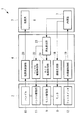
コントローラ4は、図2に示されるように、内視鏡7のカメラ13により取得された画像信号に基づいて画像を生成し、モニタ8に出力する画像生成部18を備えている。
また、コントローラ4は、フットスイッチ12の踏み込み量に基づいて内視鏡7の各モータの作動量を算出し、各モータに指令する内視鏡制御部19を備えている。内視鏡制御部19は、例えば、医師がフットスイッチ12を踏み込むと、内視鏡7を長手方向に前進させるとともに各湾曲部7a,7bの湾曲角度を増大させるようになっている。これにより、カメラ13の光軸13aは、患部に交差させられたままの状態で、水平面6Aに対する角度αを増大させられるようになっている。
As shown in FIG. 2, the
The
また、コントローラ4は、医師Dによるハンドル10の操作量に基づいて、処置具アーム6bおよび鉗子6aの各モータの作動量を算出し、各モータに指令する処置具制御部20を備えている。
処置具制御部20は、例えば、医師Dがハンドル10のグリップ10aを把持していくと、鉗子6aが閉じられ、グリップ10aを解放していくと、鉗子6aが開かれるように鉗子6aのモータを制御するようになっている。
Further, the
For example, when the doctor D grips the
また、処置具制御部20は、医師Dがハンドル10を水平方向に前進させると、位置検出部により検出された水平方向の移動量に基づいて、鉗子6aの位置を前進させる移動量を算出し、処置具アーム6bの関節を伸ばして、鉗子6aの位置を前進させるようになっている。
In addition, when the doctor D advances the
また、コントローラ4は、内視鏡7のモータに備えられたエンコーダにより検出された2つの湾曲部7a,7bの湾曲角度が入力されて、モニタ駆動部9を制御するモニタ駆動制御部21と、ハンドル駆動部11を制御するハンドル駆動制御部22とを備えている。
Further, the
モニタ駆動制御部21は、2つの湾曲部7a,7bの湾曲角度に基づいて、カメラ13の光軸13aが水平面6Aに対してなす角度αを算出し、モニタ8の接眼部8aの光軸が水平面に対してなす角度βをカメラ13の光軸13aの角度αに一致させるようにモニタ駆動部9を制御するようになっている。
すなわち、本実施形態においては、モニタ駆動制御部21は、角度αと角度βとが、図3に示されるような正比例の関係で変化する関数(第1の関数)に基づいて変化するように、モニタ駆動部9を制御するようになっている。
The monitor
That is, in the present embodiment, the monitor
また、モニタ駆動制御部21は、揺動アクチュエータ14bを作動させてモニタ用アーム14のベース部14aに対するモニタ8の角度βを、カメラ13の光軸13aの角度αに一致するように制御するだけでなく、これとともに、直動アクチュエータ16を作動させて、支持フレーム15に対するモニタ用アーム14の水平方向および鉛直方向位置を調節するようになっている。
Further, the monitor
すなわち、本実施形態においては、図1(a)に示されるように、モニタ駆動制御部21は、医師Dの首の位置に配置される頭部の回転中心Pの位置座標を記憶している。そして、モニタ駆動制御部21は、この回転中心Pを中心とした鉛直面内の円Sに沿ってモニタ8の接眼部8aが移動するように、揺動アクチュエータ14bと直動アクチュエータ16とを同期して作動させるようになっている。
That is, in this embodiment, as shown in FIG. 1A, the monitor
また、ハンドル駆動制御部22は、モニタ8の接眼部8aとグリップ10aとの相対位置関係が、カメラ13と処置具6との相対位置関係に一致するようにハンドル駆動部11を制御するようになっている。ここで、相対位置関係が一致するとは、カメラ13の光軸13aと水平面6Aとの角度αが、接眼部8aとグリップ10aとを結ぶ直線と水平面との角度γと略一致することを意味し、角度αと角度γとが、図3に示されるような正比例の関係で変化する関数(第2の関数)に基づいて変化するように、ハンドル駆動部11を制御するようになっている。
In addition, the handle
本実施形態においては、ハンドル駆動制御部22は、上述したように角度αと角度γとが一致し、かつ、カメラ13と処置具6との距離と接眼部8aとグリップ10aとの距離との比が、一定となる(例えば、1:10となる)ようにハンドル駆動部11を制御するようになっている。
これにより、図1(a)に示されるように、カメラ13の光軸13aの水平面6Aに対する角度αと一致する角度βで傾斜したモニタ8の接眼部8aの光軸の延長上にグリップ10aが配置されるようになっている。
In the present embodiment, as described above, the handle
Thereby, as shown in FIG. 1A, the
このように構成された本実施形態に係るマニピュレータシステム1の作用について、以下に説明する。
本実施形態に係るマニピュレータシステム1を用いて医師Dが患者の患部Aを処置する場合には、スレーブ装置3の内視鏡7および処置具6を患者の体内の患部Aに近接して配置し、内視鏡7のカメラ13により患部Aおよび処置具6を撮影する。
The operation of the manipulator system 1 according to this embodiment configured as described above will be described below.
When the doctor D treats the affected area A of the patient using the manipulator system 1 according to the present embodiment, the
内視鏡7により取得された画像情報は、コントローラ4の画像生成部18に送られ、画像生成部18においてモニタ8に表示される画像が生成される。生成された画像はマスタ装置2のモニタ8に送られて、モニタ8に備えられたディスプレイに表示される。
Image information acquired by the
また、医師Dは、マスタ装置2のグリップ10aを握り、フットスイッチ12に足をおくとともに、モニタ8の接眼部8aに眼をあてて、ディスプレイに表示されている画像を観察する。モニタ駆動制御部21は、カメラ13の光軸13aの角度αとモニタ8の角度βとを一致させ、かつ、接眼部8aが予め記憶されている医師Dの首の回転中心Pを中心とした医師Dの眼を通過する円S上に配置されるようにモニタ駆動部9を制御する。これにより、医師Dが接眼部8aに眼をあてると、自然な姿勢で、ディスプレイに表示された画像を観察することができる。
The doctor D grasps the
また、ハンドル駆動制御部22は、接眼部8aとグリップ10aとを結ぶ直線の水平面に対する角度γが、カメラ13の光軸13aの水平面6Aに対する角度αと一致するようにハンドル駆動部11を制御するので、接眼部8aを介して画像を見ている医師Dは、両手で把持しているグリップ10aがあたかも画像上の処置具6と同じものであるかのように認識することができる。
The handle
すなわち、医師Dが両手で把持しているグリップ10aの把持の度合いを変化させることにより、これに同期させて画像内の処置具6を開閉することができ、画像上の処置具6の前後方向に一致する方向にグリップ10aを押し引きすると、グリップ10aが前後方向に動き、これに同期させて画像内の処置具6を前後に移動させることができる。
That is, by changing the degree of gripping of the
また、医師Dが患部Aおよび処置具6の観察角度を変更したい場合には、フットスイッチ12を足で操作する。これにより、フットスイッチ12の踏み込み量がコントローラ4内の内視鏡制御部19に送信され、内視鏡制御部12が、踏み込み量に応じて内視鏡7の2つの湾曲部7a,7bの湾曲角度を変化させる。例えば、図1(b)に示される状態から、フットスイッチ12の踏み込み量を変化させると、図4(b)に示されるように、カメラ13の光軸13aの水平面6Aに対する角度αが大きくなるように2つの湾曲部7a,7bの湾曲角度が変化する。
When the doctor D wants to change the observation angle of the affected part A and the
その結果、モニタ8内のディスプレイに表示される画像は、図5の状態から図6の状態に変化する。
そして、内視鏡7の湾曲部7a,7bの湾曲角度が変化すると、湾曲部7a,7bを駆動するモータのエンコーダにより検出された角度がモニタ駆動制御部21およびハンドル駆動制御部22に送られる。
As a result, the image displayed on the display in the
When the bending angles of the bending
モニタ駆動制御部21は、エンコーダにより検出された各湾曲部7a,7bの角度から内視鏡7のカメラ13の光軸13aの水平面6Aに対する角度αを算出し、該角度αに基づいて、モニタ8の揺動角度βを角度αに一致するように揺動アクチュエータ14bを作動させる。画像における患部Aおよび処置具6の観察方向の変化に合わせて、図4(a)に示されるように、モニタ8の揺動角度βを変化させることで、あたかも自身の視線の方向を変えることで患部A等の観察方向を変えたかのように医師Dに感じさせることができ、処置具6のより直感的な操作を可能にすることができる。
The monitor
この場合において、モニタ駆動制御部21は、モニタ8の接眼部8aが、医師Dの首を湾曲させる中心位置Pを中心とした円Sに沿って移動するように、揺動アクチュエータ14bおよび直動アクチュエータ14aを同期して作動させ、角度βが角度αに一致した時点で、両アクチュエータ14a,14bの作動を停止する。これにより、医師Dは、身体の他の部分を動かすことなく首の傾きを変えるだけで、常に、無理のない姿勢で接眼部8aからディスプレイに表示された画像を観察することができる。
In this case, the monitor
さらに、本実施形態によれば、ハンドル駆動制御部22が、エンコーダにより検出された各湾曲部7a,7bの角度から内視鏡7のカメラ13の光軸13aの水平面6Aに対する角度αを算出し、該角度αに基づいて、ハンドル駆動部11を制御する。すなわち、ハンドル駆動制御部22は、接眼部8aとグリップ10aとを結ぶ直線の水平面に対する角度γが、図4(a)に示されるように、カメラ13の光軸13aの水平面6Aに対する角度αと一致するようにハンドル駆動部11を制御するので、接眼部8aを介して画像を見ている医師Dは、画像上の処置具6が常にグリップ10aの位置にあるかのように認識することができる。
Furthermore, according to the present embodiment, the handle
さらに具体的には、接眼部8aを介してディスプレイに表示された画像を見ている医師Dにとって、処置具6の移動方向は、図5の状態では、ディスプレイ画面に交差する方向であったのに対し、図6の状態では、よりディスプレイ画面に沿う方向に変化している。そして、医師Dはグリップ10aを画像上の処置具6の移動方向に一致する方向に移動させることにより、処置具6を進退させることができる。したがって、グリップ10aの直感的な操作により処置具6を駆動させることができ、患部Aの処置をより容易にすることができるという利点がある。
More specifically, for the doctor D who is viewing an image displayed on the display via the
なお、本実施形態においては、外套管5として、硬質な直管状の部材を例示したが、これに限定されるものではなく、処置具6および内視鏡7の方向を一体的に変化させるように、長手方向の途中位置に湾曲部(図示略)を有するものを採用してもよい。外套管5の湾曲部の湾曲方向は、水平方向、鉛直方向およびこれらを組み合わせた方向のいずれであってもよい。
In the present embodiment, a hard straight tubular member is exemplified as the
また、本実施形態においては、内視鏡7の湾曲部7a,7bを湾曲させるモータに備えられたエンコーダによる検出信号に基づいて、カメラ13の光軸13aの水平面6Aに対する角度αをモニタ駆動制御部21およびハンドル駆動制御部22がそれぞれ算出することとしたが、これに代えて、図7に示されるように、共通の角度算出部23を配置し、該角度算出部23により算出された角度αをモニタ駆動制御部21およびハンドル駆動制御部22に入力することにしてもよい。
In the present embodiment, the monitor α controls the angle α of the
また、本実施形態においては、比例係数1の正比例関数である第1の関数および第2の関数に基づいて、モニタ8の角度βおよび接眼部8aとグリップ10aとを結ぶ直線の角度γを調節することとしたが、これに代えて、図8に示される第1、第2の関数を使用してもよい。
In the present embodiment, the angle β of the
図8の第1、第2の関数は、カメラ13の光軸13aの角度αの角度範囲(0°〜90°)が5つの領域に区画され、中央の領域(40°〜50°)において、角度β,γが比例係数1の正比例関数として表され、その両側の4つの領域(0°〜20°、20°〜40°、50°〜70°、70°〜90°)においては、角度範囲の両端に向かうに従って傾きが徐々に小さくなり、角度範囲全体としては不連続な関数となっている。図中、鎖線は、比例係数1で正比例する図3の関数を示している。
The first and second functions of FIG. 8 are obtained by dividing the angle range (0 ° to 90 °) of the angle α of the
これら第1の関数および第2の関数は、それぞれ、図9に示されるように、モニタ駆動制御部21およびハンドル駆動制御部22に接続される記憶部24,25に記憶されていればよい。そして、角度算出部23により算出された角度αに基づいて、モニタ駆動制御部21およびハンドル駆動制御部22が記憶部24,25内に記憶されている第1の関数および第2の関数によって角度βおよび角度γを算出することにしてもよい。
The first function and the second function may be stored in the
図8に示す例では、フットスイッチ12の操作によって内視鏡7の湾曲部7a,7bの角度が変化し、カメラ13の光軸13aの角度αが40°〜50°の角度範囲で変化する場合には、モニタ駆動制御部21およびハンドル駆動制御部22はモニタ8の角度βおよび接眼部8aとグリップ10aとを結ぶ直線の角度γを角度αに一致させるように制御するようになっている。
In the example shown in FIG. 8, the angle of the bending
また、カメラ13の光軸13aの角度αが20°〜40°、50°〜70°の角度範囲で変化する場合には、モニタ駆動制御部21およびハンドル駆動制御部22は、角度βおよび角度γを角度αに比例係数0.5を乗算した値となるように制御するようになっている。さらに、カメラ13の光軸13aの角度αが0°〜20°、70°〜90°の角度範囲で変化する場合には、モニタ駆動制御部21およびハンドル駆動制御部22は、角度βおよび角度γを角度αに比例係数0.1を乗算した値となるように制御するようになっている。
When the angle α of the
図3に示されるように、角度αの全角度範囲にわたって、角度β,γが比例係数1で正比例する場合には、角度αがその角度範囲の両端に近づくほど、グリップ10aが医師Dの身体から離れすぎたり近づき過ぎたりして、医師Dの姿勢が窮屈になる。これに対して、図8の第1の関数および第2の関数を使用することにより、角度αの角度範囲の両端におけるモニタ8およびグリップ10aの移動量が少なくなる。これにより、グリップ10aの直感的な操作を可能としながら、姿勢が窮屈になり過ぎないようにすることができるという利点がある。
As shown in FIG. 3, when the angles β and γ are directly proportional to the proportional coefficient 1 over the entire angle range of the angle α, the
なお、本実施形態においては、比例係数を1,0.5,0.1としたが、これに限定されるものではなく、任意のものを採用することができる。
また、角度範囲の領域分割についても、上記分割に限定されるものではなく任意に設定することができる。
また、角度範囲の最も端に位置する領域においては、角度αの変化に関わらず、角度β、γを変化させないことにしてもよい。
In the present embodiment, the proportionality coefficient is set to 1, 0.5, 0.1. However, the present invention is not limited to this, and an arbitrary one can be adopted.
In addition, the area division of the angle range is not limited to the above division, and can be arbitrarily set.
In the region located at the extreme end of the angle range, the angles β and γ may not be changed regardless of the change in the angle α.
また、領域毎に比例係数を不連続に変化させることとしたが、図10に示されるように、有限の領域に分けることなく、連続的に変化する関数を使用してもよい。
また、図11に示されるように、角度αの全角度範囲にわたって、1より小さい比例係数で比例する関数を採用してもよい。このようにしても、接眼部8aとグリップ10aとの相対位置関係がカメラ13と処置具6との相対位置関係に近づくようにモニタ8およびグリップ10aが作動させられるので、グリップ10aの操作の直感性は維持される。
Further, although the proportionality coefficient is changed discontinuously for each region, as shown in FIG. 10, a continuously changing function may be used without being divided into finite regions.
Further, as shown in FIG. 11, a function proportional to a proportional coefficient smaller than 1 may be adopted over the entire angle range of the angle α. Even in this case, since the
また、第1の関数および第2の関数を同じ関数としたが、これに限定されるものではなく、異なる関数を使用してもよい。また、第1,第2の関数のいずれか一方については、比例係数1の正比例関数を採用してもよい。 Moreover, although the 1st function and the 2nd function were made into the same function, it is not limited to this, You may use a different function. Further, for either one of the first and second functions, a direct proportional function having a proportional coefficient 1 may be adopted.
また、上記実施形態においては、内視鏡7として、カメラ13の光軸13aが内視鏡7の長手方向に一致する直視形式の内視鏡7を例示したが、側視形式または斜視形式の内視鏡7を採用してもよい。この場合に、内視鏡7の湾曲部7a,7bの湾曲角度とカメラ13の光軸13aの角度αとの関係はそれぞれ異なる。
Moreover, in the said embodiment, although the
そこで、図12に示されるように、内視鏡7に備えられた形式情報を読み取る読み取り部26と、形式情報に対応づけて補正情報を記憶する補正情報記憶部27とを備えていて、角度算出部23が、該読み取り部26によって読み取られた形式情報を用いて補正情報記憶部27内から読み出した補正情報を用いて角度αを算出することにしてもよい。
Therefore, as shown in FIG. 12, the
また、マスタ装置2とスレーブ装置3とは相互に近接して配置され、相互に電気的に接続されていてもよいし、相互に遠隔に配置され、無線送信によって信号の授受を行うことにしてもよい。
In addition, the
A 患部(被写体)
α 角度(撮影角度)
β 角度(表示部角度)
γ 角度(操作部角度)
1 マニピュレータシステム
4 コントローラ(制御部)
6 処置具(処置部)
8 モニタ(表示部)
9 モニタ駆動部(表示部駆動部)
10 ハンドル(操作部)
11 ハンドル駆動部(操作部駆動部)
13 カメラ(撮影部)
24,25 記憶部(関数記憶部)
A affected area (subject)
α angle (shooting angle)
β angle (display unit angle)
γ angle (operation unit angle)
1
6 treatment tools (treatment section)
8 Monitor (display section)
9 Monitor drive unit (display unit drive unit)
10 Handle (operation part)
11 Handle drive unit (operation unit drive unit)
13 Camera (shooting unit)
24, 25 storage unit (function storage unit)
Claims (13)
前記被写体および処置部を撮影する撮影部と、
該撮影部により取得された画像を表示する表示部と、
該表示部を支持して移動させる表示部駆動部と、
前記処置部を操作する操作部と、
該操作部を支持して移動させる操作部駆動部と、
前記表示部と前記操作部との相対位置関係を、前記処置部と前記撮影部との相対位置関係に近づけるように前記表示部駆動部および前記操作部駆動部を制御する制御部とを備えるマニピュレータシステム。 A treatment section for treating a subject;
An imaging unit for imaging the subject and the treatment unit;
A display unit for displaying an image acquired by the photographing unit;
A display drive unit for supporting and moving the display unit;
An operation unit for operating the treatment unit;
An operation unit drive unit that supports and moves the operation unit;
A manipulator comprising: a control unit that controls the display unit driving unit and the operation unit driving unit so that a relative positional relationship between the display unit and the operation unit approaches a relative positional relationship between the treatment unit and the imaging unit. system.
前記制御部が、検出部により検出された撮影角度に基づいて、前記表示部駆動部および前記操作部駆動部を制御する請求項1に記載のマニピュレータシステム。 A detection unit for detecting a shooting angle of the subject by the shooting unit;
The manipulator system according to claim 1, wherein the control unit controls the display unit driving unit and the operation unit driving unit based on an imaging angle detected by the detection unit.
前記制御部が、前記撮影角度、前記操作部角度および前記表示部角度を一致させるように前記表示部駆動部および前記操作部駆動部を制御する請求項3に記載のマニピュレータシステム。 The operation unit driving unit changes an operation unit angle that is an angle with respect to a horizontal direction of a straight line connecting the operation unit and the display unit,
4. The manipulator system according to claim 3, wherein the control unit controls the display unit driving unit and the operation unit driving unit so that the imaging angle, the operation unit angle, and the display unit angle coincide with each other.
前記制御部が、前記関数記憶部に記憶されている前記第1の関数に基づいて、前記表示部駆動部を制御する請求項3に記載のマニピュレータシステム。 A function storage unit that stores a first function indicating a relationship between the shooting angle and the display unit angle;
The manipulator system according to claim 3, wherein the control unit controls the display unit driving unit based on the first function stored in the function storage unit.
前記制御部が、前記関数記憶部に記憶されている前記第2の関数に基づいて、前記操作部駆動部を制御する請求項4に記載のマニピュレータシステム。 A function storage unit that stores a second function indicating a relationship between the shooting angle and the operation unit angle;
The manipulator system according to claim 4, wherein the control unit controls the operation unit driving unit based on the second function stored in the function storage unit.
Priority Applications (5)
| Application Number | Priority Date | Filing Date | Title |
|---|---|---|---|
| JP2012134687A JP5941762B2 (en) | 2012-06-14 | 2012-06-14 | Manipulator system |
| EP13804620.6A EP2862497B1 (en) | 2012-06-14 | 2013-04-24 | Manipulator system |
| CN201380031050.XA CN104394751B (en) | 2012-06-14 | 2013-04-24 | Arm-and-hand system |
| PCT/JP2013/062071 WO2013187136A1 (en) | 2012-06-14 | 2013-04-24 | Manipulator system |
| US14/520,857 US20150038984A1 (en) | 2012-06-14 | 2014-10-22 | Manipulator system |
Applications Claiming Priority (1)
| Application Number | Priority Date | Filing Date | Title |
|---|---|---|---|
| JP2012134687A JP5941762B2 (en) | 2012-06-14 | 2012-06-14 | Manipulator system |
Publications (2)
| Publication Number | Publication Date |
|---|---|
| JP2013255736A JP2013255736A (en) | 2013-12-26 |
| JP5941762B2 true JP5941762B2 (en) | 2016-06-29 |
Family
ID=49757971
Family Applications (1)
| Application Number | Title | Priority Date | Filing Date |
|---|---|---|---|
| JP2012134687A Expired - Fee Related JP5941762B2 (en) | 2012-06-14 | 2012-06-14 | Manipulator system |
Country Status (5)
| Country | Link |
|---|---|
| US (1) | US20150038984A1 (en) |
| EP (1) | EP2862497B1 (en) |
| JP (1) | JP5941762B2 (en) |
| CN (1) | CN104394751B (en) |
| WO (1) | WO2013187136A1 (en) |
Families Citing this family (8)
| Publication number | Priority date | Publication date | Assignee | Title |
|---|---|---|---|---|
| US10285765B2 (en) | 2014-05-05 | 2019-05-14 | Vicarious Surgical Inc. | Virtual reality surgical device |
| JP6104479B2 (en) * | 2015-02-26 | 2017-03-29 | オリンパス株式会社 | Manipulator system |
| US10799308B2 (en) | 2017-02-09 | 2020-10-13 | Vicarious Surgical Inc. | Virtual reality surgical tools system |
| WO2018225818A1 (en) * | 2017-06-08 | 2018-12-13 | 株式会社メディカロイド | Remote operation device, display device, remote operation system, surgery assistance system, and method for exchanging display device of remote operation device |
| EP3636198A4 (en) * | 2017-06-08 | 2020-06-24 | Medicaroid Corporation | Remote operation device and remote operation system |
| EP3681368A4 (en) | 2017-09-14 | 2021-06-23 | Vicarious Surgical Inc. | Virtual reality surgical camera system |
| CN109498162B (en) * | 2018-12-20 | 2023-11-03 | 深圳市精锋医疗科技股份有限公司 | Main operation table for improving immersion sense and surgical robot |
| CN109498163B (en) * | 2018-12-20 | 2023-07-14 | 深圳市精锋医疗科技股份有限公司 | Main operation table and surgical robot |
Family Cites Families (27)
| Publication number | Priority date | Publication date | Assignee | Title |
|---|---|---|---|---|
| US6963792B1 (en) * | 1992-01-21 | 2005-11-08 | Sri International | Surgical method |
| US6731988B1 (en) * | 1992-01-21 | 2004-05-04 | Sri International | System and method for remote endoscopic surgery |
| JP3402797B2 (en) * | 1994-11-07 | 2003-05-06 | オリンパス光学工業株式会社 | Endoscope image display system |
| US6318864B1 (en) * | 1994-11-15 | 2001-11-20 | Olympus Optical Co., Ltd. | Sterile instruments cover for use on surgical microscopes |
| JP3610110B2 (en) * | 1995-02-23 | 2005-01-12 | オリンパス株式会社 | Medical manipulator |
| US8206406B2 (en) * | 1996-12-12 | 2012-06-26 | Intuitive Surgical Operations, Inc. | Disposable sterile surgical adaptor |
| US6286794B1 (en) * | 1999-06-14 | 2001-09-11 | Bradley Harbin | Ergonomic computer mounting device permitting extensive vertical, horizontal and angular ranges of motion |
| US8004229B2 (en) * | 2005-05-19 | 2011-08-23 | Intuitive Surgical Operations, Inc. | Software center and highly configurable robotic systems for surgery and other uses |
| US8253779B2 (en) * | 2000-10-11 | 2012-08-28 | University of Pittsbugh—Of The Commonwealth System of Higher Education | System for remote guidance by expert for imaging device |
| JP2003230073A (en) * | 2002-02-01 | 2003-08-15 | Olympus Optical Co Ltd | Observation apparatus |
| US8010180B2 (en) * | 2002-03-06 | 2011-08-30 | Mako Surgical Corp. | Haptic guidance system and method |
| US20040097791A1 (en) * | 2002-11-13 | 2004-05-20 | Olympus Corporation | Endoscope |
| CN100413478C (en) * | 2002-12-06 | 2008-08-27 | 皇家飞利浦电子股份有限公司 | Apparatus and method for automated positioning of a device |
| US8118732B2 (en) * | 2003-04-01 | 2012-02-21 | Boston Scientific Scimed, Inc. | Force feedback control system for video endoscope |
| JP2005245961A (en) * | 2004-03-08 | 2005-09-15 | Olympus Corp | Image processing apparatus |
| JP2006042913A (en) * | 2004-07-30 | 2006-02-16 | Olympus Corp | Image observation apparatus |
| WO2007097034A1 (en) * | 2006-02-27 | 2007-08-30 | Olympus Medical Systems Corp. | Endoscope surgery operation instrument |
| US7841980B2 (en) * | 2006-05-11 | 2010-11-30 | Olympus Medical Systems Corp. | Treatment system, trocar, treatment method and calibration method |
| JP4911701B2 (en) * | 2007-01-19 | 2012-04-04 | 株式会社日立製作所 | Master / slave manipulator system |
| WO2008109346A1 (en) * | 2007-03-05 | 2008-09-12 | University Of Pittsburgh - Of The Commonwealth System Of Higher Education | Combining tomographic images in situ with direct vision in sterile environments |
| US8864652B2 (en) * | 2008-06-27 | 2014-10-21 | Intuitive Surgical Operations, Inc. | Medical robotic system providing computer generated auxiliary views of a camera instrument for controlling the positioning and orienting of its tip |
| KR100936928B1 (en) * | 2008-07-25 | 2010-01-20 | (주)미래컴퍼니 | Surgical robot |
| US8120301B2 (en) * | 2009-03-09 | 2012-02-21 | Intuitive Surgical Operations, Inc. | Ergonomic surgeon control console in robotic surgical systems |
| US8543240B2 (en) * | 2009-11-13 | 2013-09-24 | Intuitive Surgical Operations, Inc. | Master finger tracking device and method of use in a minimally invasive surgical system |
| JP5825753B2 (en) * | 2009-11-17 | 2015-12-02 | 富士フイルム株式会社 | Biopsy equipment |
| US9259289B2 (en) * | 2011-05-13 | 2016-02-16 | Intuitive Surgical Operations, Inc. | Estimation of a position and orientation of a frame used in controlling movement of a tool |
| US10314559B2 (en) * | 2013-03-14 | 2019-06-11 | Inneroptic Technology, Inc. | Medical device guidance |
-
2012
- 2012-06-14 JP JP2012134687A patent/JP5941762B2/en not_active Expired - Fee Related
-
2013
- 2013-04-24 WO PCT/JP2013/062071 patent/WO2013187136A1/en unknown
- 2013-04-24 CN CN201380031050.XA patent/CN104394751B/en active Active
- 2013-04-24 EP EP13804620.6A patent/EP2862497B1/en not_active Not-in-force
-
2014
- 2014-10-22 US US14/520,857 patent/US20150038984A1/en not_active Abandoned
Also Published As
| Publication number | Publication date |
|---|---|
| CN104394751B (en) | 2017-07-11 |
| JP2013255736A (en) | 2013-12-26 |
| EP2862497A4 (en) | 2016-03-09 |
| CN104394751A (en) | 2015-03-04 |
| EP2862497B1 (en) | 2018-03-21 |
| US20150038984A1 (en) | 2015-02-05 |
| WO2013187136A1 (en) | 2013-12-19 |
| EP2862497A1 (en) | 2015-04-22 |
Similar Documents
| Publication | Publication Date | Title |
|---|---|---|
| JP5941762B2 (en) | Manipulator system | |
| JP7248554B2 (en) | Systems and methods for controlling the orientation of an imaging instrument | |
| US8315720B2 (en) | Method for graphically providing continuous change of state directions to a user of a medical robotic system | |
| JP7081584B2 (en) | Medical observation system, control device and control method | |
| US8335590B2 (en) | System and method for adjusting an image capturing device attribute using an unused degree-of-freedom of a master control device | |
| JP6203249B2 (en) | Master-slave system | |
| JP7015256B2 (en) | Auxiliary device control in computer-aided remote control system | |
| JP5846385B2 (en) | Endoscope operation system | |
| JP6673684B2 (en) | Remote control device and remote operation system | |
| JP6132904B2 (en) | Master-slave system and its operation method | |
| JP2020044354A (en) | Remote operation device and remote operation system | |
| JP2014008374A (en) | Surgical operation support device | |
| CN114126532A (en) | Movable display system | |
| JP6097390B2 (en) | Medical manipulator | |
| JP6778326B2 (en) | Master operation input device and master-slave manipulator | |
| JP2022545684A (en) | Movable display unit on track | |
| JP2018075395A (en) | Remote handling equipment and remote surgery system | |
| JP2024009700A (en) | Surgery system and operation method of surgery system |
Legal Events
| Date | Code | Title | Description |
|---|---|---|---|
| A621 | Written request for application examination |
Free format text: JAPANESE INTERMEDIATE CODE: A621 Effective date: 20150414 |
|
| TRDD | Decision of grant or rejection written | ||
| A01 | Written decision to grant a patent or to grant a registration (utility model) |
Free format text: JAPANESE INTERMEDIATE CODE: A01 Effective date: 20160426 |
|
| A61 | First payment of annual fees (during grant procedure) |
Free format text: JAPANESE INTERMEDIATE CODE: A61 Effective date: 20160523 |
|
| R151 | Written notification of patent or utility model registration |
Ref document number: 5941762 Country of ref document: JP Free format text: JAPANESE INTERMEDIATE CODE: R151 |
|
| LAPS | Cancellation because of no payment of annual fees |