EP1577983A2 - Boitier électrique de jonction - Google Patents
Boitier électrique de jonction Download PDFInfo
- Publication number
- EP1577983A2 EP1577983A2 EP05251643A EP05251643A EP1577983A2 EP 1577983 A2 EP1577983 A2 EP 1577983A2 EP 05251643 A EP05251643 A EP 05251643A EP 05251643 A EP05251643 A EP 05251643A EP 1577983 A2 EP1577983 A2 EP 1577983A2
- Authority
- EP
- European Patent Office
- Prior art keywords
- connector housing
- bus bar
- bus bars
- tabs
- terminal
- Prior art date
- Legal status (The legal status is an assumption and is not a legal conclusion. Google has not performed a legal analysis and makes no representation as to the accuracy of the status listed.)
- Withdrawn
Links
Images


Classifications
-
- H—ELECTRICITY
- H01—ELECTRIC ELEMENTS
- H01R—ELECTRICALLY-CONDUCTIVE CONNECTIONS; STRUCTURAL ASSOCIATIONS OF A PLURALITY OF MUTUALLY-INSULATED ELECTRICAL CONNECTING ELEMENTS; COUPLING DEVICES; CURRENT COLLECTORS
- H01R9/00—Structural associations of a plurality of mutually-insulated electrical connecting elements, e.g. terminal strips or terminal blocks; Terminals or binding posts mounted upon a base or in a case; Bases therefor
- H01R9/22—Bases, e.g. strip, block, panel
- H01R9/24—Terminal blocks
- H01R9/2458—Electrical interconnections between terminal blocks
-
- B—PERFORMING OPERATIONS; TRANSPORTING
- B60—VEHICLES IN GENERAL
- B60R—VEHICLES, VEHICLE FITTINGS, OR VEHICLE PARTS, NOT OTHERWISE PROVIDED FOR
- B60R16/00—Electric or fluid circuits specially adapted for vehicles and not otherwise provided for; Arrangement of elements of electric or fluid circuits specially adapted for vehicles and not otherwise provided for
- B60R16/02—Electric or fluid circuits specially adapted for vehicles and not otherwise provided for; Arrangement of elements of electric or fluid circuits specially adapted for vehicles and not otherwise provided for electric constitutive elements
- B60R16/023—Electric or fluid circuits specially adapted for vehicles and not otherwise provided for; Arrangement of elements of electric or fluid circuits specially adapted for vehicles and not otherwise provided for electric constitutive elements for transmission of signals between vehicle parts or subsystems
- B60R16/0238—Electrical distribution centers
-
- H—ELECTRICITY
- H01—ELECTRIC ELEMENTS
- H01R—ELECTRICALLY-CONDUCTIVE CONNECTIONS; STRUCTURAL ASSOCIATIONS OF A PLURALITY OF MUTUALLY-INSULATED ELECTRICAL CONNECTING ELEMENTS; COUPLING DEVICES; CURRENT COLLECTORS
- H01R43/00—Apparatus or processes specially adapted for manufacturing, assembling, maintaining, or repairing of line connectors or current collectors or for joining electric conductors
- H01R43/16—Apparatus or processes specially adapted for manufacturing, assembling, maintaining, or repairing of line connectors or current collectors or for joining electric conductors for manufacturing contact members, e.g. by punching and by bending
Definitions
- This invention relates to an electrical connection box and method of making a bus bar for use therein.
- the electrical junction box is for use in a motor vehicle, and has one or more external sockets for receiving a mating connector or connector containing terminals attached to wiring of the vehicle.
- Prior art electrical junction boxes for mounting on a motor vehicle, comprise an internal circuit including a flat bus bar, a vertical bus bar and/or a single core wire.
- the internal circuit is provided with tabs that project into a connector housing providing a socket at the exterior of a casing for receiving the mating connector.
- the internal circuit is connected to an external circuit through connection between the tabs and a connector arrangement.
- Figures 11 and 12 of the present application illustrate a portion of such a known electrical junction box.
- a connector housing socket 1 of the electrical junction box as shown in Figure 11, the elongation direction of terminal slots 2 formed in a bottom wall of the connector housing socket 1 is aligned with the elongation direction of the connector housing socket 1. Consequently, the length direction of a tab of an internal circuit that passes through the terminal slot 2 is also aligned with the elongation direction of the connector housing socket 1.
- an object of the present invention is to enhance flexibility in the design of circuits of an electrical junction box.
- the present invention in a first aspect provides an electrical connection box comprising:
- the elongation direction of the connector housing socket is defined herein as the direction substantially parallel to the long sides of the substantially rectangular cross-section of the connector housing socket.
- the direction perpendicular to the elongation direction of the connector housing socket should be construed accordingly, but it is also referred to herein as the 'short side' direction of the connector housing.
- the elongation (length) direction of the terminal slot is defined herein as the direction substantially parallel with the longest side edge of the terminal slot; this elongation direction of the slot corresponds to the length direction of a tab inserted into the slot.
- the orientation words “upper”, “lower”, “upwards”, “downwards”, “vertical”, “laterally”, “sideways” etc. are used for convenience of description of the electrical junction box. In actual use, the box may be arranged in any suitable orientation.
- the electrical junction box further comprises a mating connector, the mating connector being located in the connector housing socket, the mating connector comprising a terminal and a terminal chamber, the terminal being located in the terminal chamber.
- the mating connector has a substantially rectangular cross-section so that it can be received securely in the connector housing socket.
- the terminal of the mating connector is made in one-piece by folding metal sheet, and preferably the terminal has a slit shaped to receive a corresponding tab of the electrical junction box.
- the length direction of the slit i.e. the direction substantially parallel with the longest side edge of the slit, is perpendicular to the elongation direction of the mating connector.
- the tab of the internal circuit is connected to the terminal of the mating connector.
- the connector housing socket comprises a plurality of terminal slots.
- terminal slots are juxtaposed and spaced from one another along a row, the row extending in the short side direction of the connector housing socket.
- the connector housing comprises a plurality of rows of terminal slots, the rows juxtaposed in the elongation direction of the connector housing socket.
- corresponding slots of adjacent rows are shifted with respect to one another in the short side direction of the connector housing socket.
- the bus bar is a vertical bus bar, comprising an elongated main base portion, with a plurality of tabs extending from the upper and/or lower edges of the base portion.
- the elongation direction of the vertical bus bar is defined herein as the elongation direction of the main base portion.
- the internal circuit comprises a plurality of vertical bus bars juxtaposed in vertical planes in said casing in the elongated direction of the connector housing socket, each of the vertical bus bars being elongated in the direction perpendicular to the elongation direction of the connector housing socket.
- the internal circuit of an electrical junction box may be comprise one or more flat bus bars, single-core wires, and/or the like, in addition to the vertical bus bars.
- the flat bus bars are so called because they each have a main portion which lies in a plane which extends laterally or sideways (i.e. flat) relative to upper and lower casing members of the casing.
- a plurality of chambers for containing vertical bus bars are juxtaposed in the casing.
- a plurality of the juxtaposed vertical bus bars are secured, respectively, to the plurality of vertical bus bar-containing chambers.
- the connector housing socket bridges (overlies) the vertical bus bars, the bridging direction of the connector housing socket (i.e. the direction in which the connector housing socket overlies a plurality of vertical bus bars) corresponding to the elongation direction of the connector housing socket.
- the bridging direction of the connector housing is preferably the elongation direction of the connector housing, but no twisting or bending of the tabs is necessary, since the length direction of the terminal slots is in the short side direction of the connector housing. Accordingly, the vertical bus bar can be formed e.g. by punching out a conductive metal plate, with any substantial bending work eliminated. Therefore, the vertical bus bars of the present invention can be produced easily and at a low cost.
- the reason for having the bridging direction of the connector housing socket in the short side direction of the connector housing socket is negated, since no bending of the tabs is necessary when the bridging direction is in the elongated direction of the connector housing sockets. Accordingly, the connector housing can bridge many vertical bus bars without problem. Also, with this configuration, the size of the connector housing in the elongated direction need not be as large as in the prior art configuration. Accordingly, the electrical junction box can facilitate more connections in the same amount of space.
- a plurality of connector housing sockets are juxtaposed in the elongation direction of each of the plurality of vertical bus bars.
- tabs spaced away from one another and extending from the main base portions of the vertical bus bars pass through the terminal slots in each connector housing socket juxtaposed in the elongation direction of the vertical bus bars.
- terminals of a plurality of mating connectors fitted in the connector housing sockets are connected to one another via respective vertical bus bars.
- each vertical bus bar since tabs spaced away from one another on each vertical bus bar can pass through the terminal slots in more than one connector housing socket, it is possible to connect the terminals of different mating connectors, received in the respective connector housing sockets, via the vertical bus bar. If a flat bus bar were instead used to connect the terminals of the connectors, the internal circuit would become complicated and efficiency in the arrangement of the circuit would be lowered. However, according to the above construction, a simple structure can connect the terminals of the mating connectors.
- the electrical junction box may comprise one or more connector housing sockets disposed at upper and/or lower sides of the vertical bus bars. Since tabs can extend from the upper and lower edges of the main base portion of the vertical bus bars, as discussed above, the vertical bus bar can joint the terminals of mating connectors fitted in connector housing sockets disposed at the upper and lower sides of the vertical bus bar, as well as the terminals of the mating connectors fitted in the connector housings on one side only.
- corresponding terminal slots of adjacent rows may be shifted with respect to one another in the short side direction of the respective connector housing sockets, it is possible to arrange the terminals of the mating connector to be connected to the tabs at a narrow pitch, and to make a high density of junctions (connections) between the tabs of the vertical bus bars and the terminals of the mating connector.
- the corresponding tabs of adjacent vertical bus bars are shifted in the elongated direction of the vertical bus bars, in accordance with the shifted positions of the terminal slots, the positions of the tabs can be shifted similarly when multiple bus bars are formed from a single conductive metal plate. Therefore, the percentage of the conductive metal plate available to form bus bars can be increased.
- the vertical bus bars include narrow tabs for low current and wide tabs for high current.
- the narrow tabs are smaller in the length direction than the wide tabs.
- Narrow tabs and wide tabs are preferably both disposed on the upper and/or lower edges of the main base portion of the juxtaposed vertical bus bars, the tabs being juxtaposed and spaced in the elongated direction of the vertical bus bars.
- the terminal slots for receiving the narrow tabs are preferably disposed at a small pitch on one side of the bottom wall of the connector housing, whilst the terminal slots for receiving the wide tabs are preferably disposed at a greater pitch on the opposite side of the bottom wall of the connector housing socket.
- the tabs for low current can be made narrow, with pitch set to be small, it is possible to shorten the lengths of the vertical bus bar and the short side direction of the connector containing-section, thereby permitting a reduction in size of the electrical junction box.
- one or more securing elements are provided on the upper and/or lower edges of the main base portion of the vertical bus bars.
- the vertical bus bars can be fixed to the casing by the securing elements.
- the securing elements can be pushed and received into complementary recesses of the casing. Therefore, it may be possible to steadily receive and fix the vertical bus bars in respective vertical bus bar containing chambers during construction of the electrical junction box.
- the casing includes upper and lower casing members
- the upper casing member is joined to the lower casing member after the vertical bus bars are received in vertical bus bar containing chambers of the lower casing member
- the tabs of the vertical bus bars it is possible for the tabs of the vertical bus bars to pass easily through respective terminal slots of connector housing sockets in the upper casing member, since the vertical bus bars can be held firmly in position in the vertical bus bar containing chambers by the securing elements.
- the securing elements are fixed at points between connector housings, or at positions corresponding to a hood of the connector housing, it is possible to more effectively utilize space.
- a method for forming a vertical bus bars for use in an electrical connection box of the first aspect of the invention comprising the steps of:
- corresponding tabs of the vertical bus bars are shifted between adjacent vertical bus bars in the elongation direction of the vertical bus bars.
- each end of the vertical bus bars is coupled, through a respective thin notched-portion, or scored portion, to the respective carrier portion.
- the score of at least one of the scored portions is provided on a straight line.
- the method further comprises the steps of:
- the carrier portions couple the opposite ends of the vertical bus bars to each other, the carrier portions can protect the vertical bus bars from external interferences during transportation etc., and can allow for easily handling of the vertical bus bars.
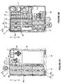
- FIGS 1 to 8 show a first embodiment of an electrical junction box in accordance with the present invention.
- the electrical junction box 10 has a casing including an upper casing member 11 and a lower casing member 12, both formed of moulded plastics material.
- An internal circuit is accommodated in the casing.
- the internal circuit includes vertical bus bars 20, a lamination body 32 in which flat bus bars 30 and insulation plates 31 are laminated alternately, and a printed circuit board 40.
- the vertical buss bars 20 are so called because they each have a main base portion 23 which lies in a place which extends upwardly and downwardly (vertically) relative to the upper and lower casing members 11, 12.
- the flat bus bars 30 are so called because they each have a main portion which lies in a place which extends laterally or sideways (i.e. flat) relative to the upper and lower casing members 11, 12.
- the electrical junction box 10 is divided laterally into a first half side, which is an arrangement area S1 for the vertical bus bars 20 (the area enclosed by an alternate long and short dash line in Figures 2A and 2B) in which a plurality of the vertical bus bars 20 are juxtaposed, and a second half side, which is an arrangement area S2 for flat bus bars (an area enclosed by an alternate long and short two-dashes line in Figures 2A and 2B) in which the lamination body 32 including the flat bus bars 30 and insulation plates 31 are disposed.
- a plurality of rectangular connector housing sockets 14, 15 provide respective recesses at the exteriors of the upper and lower casing members 11, 12 of the casing, in the arrangement area S1.
- Elongate terminal slots 14b, 15b are formed in bottom walls 14a, 15a of the recesses of the sockets 14, 15.
- the length direction X of the terminal slots 14b, 15b is perpendicular to the elongation direction Y of the sockets 14, 15.
- the slots 14b, 15b are spaced from one another in rows, each row extending in a direction perpendicular to the elongation direction Y of the sockets 14, 15, corresponding slots 14b, 15b of adjacent rows being offset with respect to one another in the direction perpendicular to the elongation direction Y.
- a plurality of vertical bus bar containing-chambers 13 are provided in the arrangement area S1 for the vertical bus bars 20 in the lower casing member 12.
- the chambers 13 extend from the boundary between the arrangement area S1 and the arrangement area S2 to the other side of the arrangement area S1.
- a main base portion 23 of each vertical bus bar 20 is pushed into and thereby secured in the respective chamber 13.
- a plurality of connector housing sockets 14, 15 (14A, 14B, 15A, 15B, 15C) are juxtaposed in the elongation direction of the vertical bus bars 20.
- the direction in which the sockets 14, 15 bridge the plurality of vertical bus bars 20 is the direction Y of the long sides of the sockets 14, 15 (i.e. the elongation direction Y of the sockets 14, 15) while the elongation direction of the vertical bus bars 20 is the direction of the short side direction of the sockets 14 and 15. Therefore, the elongation direction of the vertical bus bars 20 is perpendicular to the elongation direction Y of the sockets 14, 15 and accords with the length direction X of the terminal slots 14b, 15b.
- tabs 22, 24 extending from the vertical bus bars 20 pass through the terminal slots 14b, 15b and project into the respective recesses provided by the connector housing sockets 14, 15.
- the tabs 22, 24 can be provided on the vertical bus bar 20 without being bent.
- tabs 22 and tabs 24 extend from each vertical bus bar 20 and project into the connector housing sockets 14A, 14B, 15A to 15C in plural rows.
- Two tabs 22 extend from each vertical bus bar 20 and project into the same connector housing socket 14A and 14B.
- terminal containing-chambers 61 are provided in a staggered manner in rows in the connector 60 which is fitted into the connector housing socket 14.
- the terminal containing-chambers 61 house electrical terminals which engage the tab 22 that projects into the corresponding connector housing socket 14.
- Each terminal of the mating connector is made in one-piece by folding metal sheet, and the terminal has a slit shaped to receive the corresponding tab of the electrical connection box. These terminals are joined to wires of for example a wiring harness of a motor vehicle. Such terminals are known in the art, and need not be described here in detail.
- the slit of the terminal is aligned with the length direction of the tab of the electrical junction box, and is therefore perpendicular to the elongation direction of the mating connector. Therefore, terminals in the chamber 61 in the connector 60 are positioned with slits in a direction corresponding to that of the tab 22 that project into the socket 14 in the upper casing member 11.
- the length direction of the tabs 22 are perpendicular to the elongation direction of the rectangular connector housing socket 14.
- the tabs 22 extend from the base portion 23 of the vertical bus bar 20 and are not bent at an angle of 90 degrees.
- the slit direction of the mating terminal in the chamber 61 of the connector 60 is also positioned perpendicular to the elongation direction of the connector housing socket 14. Since the connector to be fitted in the connector housing socket 15 in the lower casing member 12 has the same structure as the connector 60 in the upper casing member 11, discussed above, a detailed explanation will be omitted here.
- a plurality of tabs 22 are spaced away from one another and extend from each vertical bus bar 20 into the respective recesses provided by the juxtaposed connector housing sockets 14A, 14B (15A, 15B, 15C) in the arrangement area S1. Accordingly, the connectors 60 are fixed via the vertical bus bars 20 to the sockets 14A, 14B (15A, 15B, 15C), respectively.
- terminal slots 14b are provided with their length direction perpendicular to the elongation direction of the socket 14, as described above. Tabs 22 extending from each vertical bus bar 20 pass through the respective slots 14b. Thus, terminals in each connector 60 are connected via tabs 14b of the same vertical bus bar 20.
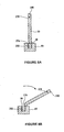
- first vertical bus bar 20A shown in Figure 5A
- second vertical bus bar 20B shown in Figure 5B
- the first vertical bus bar 20A includes a plurality of tabs 22, 24 that are spaced away from one another and disposed at both the upper and lower edges of the base portion 23.
- the second vertical bus bar 20B includes a plurality of tabs 22 that are spaced away from one another and disposed at only the upper edge of the base portion 23.
- the first and second vertical bus bars 20A and 20B each include securing elements 25 that extend e.g. downward from the lower edge of the base portion 23 and secures the bus bars 20A and 20B to the lower casing member 12.
- the elements 25 may be provided on the upper edge or both upper and lower edges of the base portion 23.
- the first vertical bus bar 20A includes tabs 22 that extend upward from the base portion 23 and project into the connector housing socket 14 in the upper casing member 11, whilst the second vertical bus bar 20B includes tabs 24 that extend downward from the base portion 23 and project into the socket 15 in the lower casing member 12.
- the second vertical bus bar 20B is shown in Figure 6 with tabs 22, that extend upwards from the base portion 23, disposed in the recess provided by the socket 14 in the upper casing member 11.
- the second vertical bus bar 20B may be disposed at a location where no socket 15 is provided in the lower casing member 12, or at a location opposing a hood.
- the lower casing member 12 is provided with clamping grooves 70 provided between the connector housing sockets 15A, 15B, 15C that are juxtaposed in the elongation direction of the vertical bus bars 20.
- the clamping grooves 70 receive and clamp the securing elements 25, respectively, that extend from the lower edges of the base portion 23 of the vertical bus bars 20.
- the clamping grooves 70 have a bottom wall with a rib 71 extending upwardly therefrom into a chamber 13.
- vertical bus bars 20 are formed by punching out a conductive metal plate.
- the vertical bus bars 20 are juxtaposed with respect to each other and are connected to each other via two carrier portions 26 (26a, 26B), each provided at respective ends of each bus bar 20.
- a respective thin (0.3 to 0.4 mm in thickness) notched or scored portion 27 is provided in a coupling portion situated between the carrier portions 26 and each end of the vertical bus bar 20.
- a first scored portion 27A has a score provided in a strait line L.
- the vertical bus bars 20 connected by the carriers 26 are arranged between the carrier portions 26 in the same order as they are arranged when located in the lower casing member 12.
- the adjacent vertical bus bars 20 are arranged so that the respective upper and lower edges of the bus bars 20 are opposed to each other. That is, an upper edge 20a of each vertical bus bar 20 is opposed to the upper edge 20a of an adjacent vertical bus bar 20 on one side, whilst a lower edge 20b of each vertical bus bar 20 is opposed to a lower edge 20b of an adjacent vertical bus bar 20 on the other side.
- the tabs 22 and 24 of the vertical bus bars 20 arranged between the carrier portions 26 are staggered correspondingly. Consequently, the tabs 22, 24 of the adjacent vertical bus bars 20 are not directly opposed to each other but are shifted in the elongation direction of the vertical bus bars 20.
- one tab of one bus bar is disposed between two tabs of the adjacent bus bar, as shown in Figure 7, thereby increasing the percentage of the material of the conductive metal plate available to form vertical bus bars.
- the vertical bus bar 20 is removed from the carrier portions 26 by utilizing a vertical bus bar cutting-tool 65 having a straight carrier portion insertion groove 66.
- the insertion groove 66 has a width large enough to receive the carrier portions 26, and a depth sized so as to expose the thin scored portion 27 of a carrier portion 26 inserted into the groove 66.
- a process for removing one of the vertical bus bars 20 from the carrier portions 26, using the cutting-tool 65 includes a first step of inserting a carrier portion 26A, adjacent the scored portion 27A having the score in the straight line, into the insertion groove 66, as shown in Figure 8A.
- the vertical bus bars 20 are tilted, e.g. downward, as shown in Figure 8B, and all of the vertical bus bars 20 are removed together from the carrier portion 26A at the scored portion 27A.
- the other carrier portion 26B is inserted into the insertion groove 66 and a desired bus bar 20 is tilted , e.g. downward individually, thereby the vertical bus bar 20 is removed from the carrier 26B at the scored portion 27B.
- the thin scored portion 27B may also be provided with score in a straight line (as scored portion 27A), such that all or several vertical bus bars 20 can be tilted, e.g. downward, to remove them from the carrier portions in unison.
- the numerous vertical bus bars 20 are pushed into the chambers 13 with their first ends being aligned at the side of the arrangement area S2. Their second ends are at the opposite side of the area S1.
- a bus bar connection tab 21 extends upward and makes a press contact with a tuning fork terminal 33 of at least one of the flat bus bars 30.
- a press contact here means a pressure contact in which electrical contact is maintained by pressure exerted by the contacting parts.
- each flat bus bar 30 is positioned in the arrangement area S2 and an end portion of the flat bus bar 30 is disposed at the boundary portion between the arrangement area S2 and the arrangement area S1.
- the tuning fork terminal 33 is bent downward from an end of the flat bus bar 30 to engage the bus bar connection tab 21 of the vertical bus bar 20.
- the terminal 33 is disposed perpendicular to the bus bar connection tab 21 of the vertical bus bar 20.
- the tuning fork terminals 33 of the flat bus bars 30 are staggered laterally in the arrangement area S2 so that the vertical bus bars 20 can be arranged at a narrow pitch, i.e. close together.
- the tuning fork terminals 33 of the flat bus bars 30 are previously covered with a protection resin block 50 to protect them before they are brought into press contact with the connection tabs 21 of the vertical bus bars 20.
- the protection resin block 50 is provided with chambers containing the terminals 33, staggered in the same manner as the terminal 33.
- the connection tabs 21 of the vertical bus bar 20 are inserted into the lower ends of the chambers and are brought into press contact with the terminals 33.
- terminal portions 34 are formed on each flat bus bar 30 by bending the given portions of the bus bar 30 upward or downward.
- the terminal portions 34 project for example into a relay housing socket 16 or a fuse housing socket 17 in the upper casing member 11, or they project for example into a connector housing socket 17 or a fuse housing socket 18 in the lower casing member 12 (see Figures 2A and 2B).
- a printed board containing-section 19 is formed by a raised upper wall portion of the upper casing member 11, at a given position of the upper casing member 11.
- a printed board 40 (pcb) is accommodated in this section 19 with an insulation plate 41 interposed in the casing between the lamination body 32 and the printed board 40.
- Elongate conductor connection tabs 35 extend upward from at least one of the flat bus bars 30.
- the conductor connection tabs 35 pass through a raised connection tab support section 42 of the insulation plate 41 and the tabs are connected to conductors of the printed board 40 disposed above in the section 19 by means of soldering.
- the printed board 40 is supported at a given height in the section 19 by means of soldering the printed board 40 to board securing-tabs 36 that extend from the flat bus bar 30 and pass through securing tab supports 43.
- the length direction X of the terminal slots 14b, 15b in the connector housing sockets 14, 15 is perpendicular to the elongation direction Y of the sockets 14 and 15, and the length direction of the terminal slits of the mating connector 60 is perpendicular to the elongation direction of the mating connector 60.
- the length direction of the terminal slots 14b, 15b correspond to the length direction of the terminal slits of the mating connector 60.
- the elongation direction Y of the connector housing sockets 14, 15 is perpendicular to the length direction X of the terminal slots 14b, 15b and the vertical bus bars 20 extend in a direction perpendicular to the elongation direction Y of the sockets 14, 15. Consequently, the tabs 22, 24 extend from the vertical bus bar 20 without needing to be bent, and thus any bending step, after a step of punching out the conductive metal plate, can be omitted.
- the vertical bus bars 20 can be produced easily at low cost.
- connector housing socket 14, 15 bridge (overlie) numerous vertical bus bars 20, it is possible to connect numerous vertical bus bars 20 to a single connector 60 fitted in a respective recess provided by the connector hosing sockets 14, 15, thereby enhancing flexibility in design of circuits.
- a tab formed by bending a distal end of a flat bus bar, or a tab crimped on a single core wire, may pass through a respective terminal slot to project into the connector containing-section.
- FIGS 9 and 10 show a second embodiment of an electrical junction box in accordance with the present invention.
- a vertical bus bar 20' includes narrow tabs 22A' for low current and wide tabs 22B' for high current.
- the terms 'narrow' and 'wide' are used to describe the tabs 22A' and 22B' relative to each other, i.e. the narrow tab is shorter in its length direction than the wide tab in its length direction.
- the vertical bus bars 20' are juxtaposed so that the tabs 22A' and 22B' of the respective bus bars are disposed on the same sides of sockets 14'.
- the narrow tabs 22A' are formed on the vertical bus bar 20' such that they project through terminal slots 14b-1 into a left side area (area enclosed by dashed line in Figure 9) of a sockets 14', whilst wide tabs 22B' are formed on the vertical bus bar 20' such that they project through terminal slots 14b-2' into a right side area of the sockets 14'.
- the corresponding narrow tabs 22A' of adjacent vertical bus bars are arranged in a staggered manner, and a pitch of the narrow tabs 22A' is set to be smaller than the pitch of wide tabs 22B'.
- Terminal slots 14b-1' in the socket 14' are shorter in the length direction, in accordance with the shape of the narrow tab 22A', in order to pass the narrow tab 22A', than terminal slots 14b-2', in the length direction, which are shaped in accordance with the wide tabs 22B', in order to pass the wide tabs 22B'.
- a pitch of the terminal slots 14b-1' is set to be smaller than the pitch of the terminal slots 14b-2'.
- the narrow tabs 22A' and the wide tabs 22B' are disposed on the same side of the vertical bus bar 20', in the elongation direction of the bus bar 20', it is possible to make a tab array simple and to arrange the tabs efficiently.
- the array of mating terminals for connection to the tabs can also have a simple configuration.
Landscapes
- Engineering & Computer Science (AREA)
- Mechanical Engineering (AREA)
- Connection Or Junction Boxes (AREA)
Applications Claiming Priority (2)
| Application Number | Priority Date | Filing Date | Title |
|---|---|---|---|
| JP2004076551A JP2005269739A (ja) | 2004-03-17 | 2004-03-17 | 電気接続箱および該電気接続箱に用いる縦バスバー |
| JP2004076551 | 2004-03-17 |
Publications (2)
| Publication Number | Publication Date |
|---|---|
| EP1577983A2 true EP1577983A2 (fr) | 2005-09-21 |
| EP1577983A3 EP1577983A3 (fr) | 2005-11-16 |
Family
ID=34836546
Family Applications (1)
| Application Number | Title | Priority Date | Filing Date |
|---|---|---|---|
| EP05251643A Withdrawn EP1577983A3 (fr) | 2004-03-17 | 2005-03-17 | Boitier électrique de jonction |
Country Status (2)
| Country | Link |
|---|---|
| EP (1) | EP1577983A3 (fr) |
| JP (1) | JP2005269739A (fr) |
Cited By (1)
| Publication number | Priority date | Publication date | Assignee | Title |
|---|---|---|---|---|
| CN103515891A (zh) * | 2012-06-20 | 2014-01-15 | 住友电装株式会社 | 电气连接箱 |
Citations (3)
| Publication number | Priority date | Publication date | Assignee | Title |
|---|---|---|---|---|
| US4820172A (en) * | 1987-01-19 | 1989-04-11 | Blaupunkt-Werke Gmbh | Composite electrical connector for apparatus installed in a vehicle |
| US5711675A (en) * | 1993-03-17 | 1998-01-27 | Yasaki Corporation | Meter module, connecting device thereof, wiring harness protector, and connecting device of instrument wiring harness |
| EP1245454A2 (fr) * | 2001-03-26 | 2002-10-02 | Sumitomo Wiring Systems, Ltd. | Boite de jonction |
-
2004
- 2004-03-17 JP JP2004076551A patent/JP2005269739A/ja active Pending
-
2005
- 2005-03-17 EP EP05251643A patent/EP1577983A3/fr not_active Withdrawn
Patent Citations (3)
| Publication number | Priority date | Publication date | Assignee | Title |
|---|---|---|---|---|
| US4820172A (en) * | 1987-01-19 | 1989-04-11 | Blaupunkt-Werke Gmbh | Composite electrical connector for apparatus installed in a vehicle |
| US5711675A (en) * | 1993-03-17 | 1998-01-27 | Yasaki Corporation | Meter module, connecting device thereof, wiring harness protector, and connecting device of instrument wiring harness |
| EP1245454A2 (fr) * | 2001-03-26 | 2002-10-02 | Sumitomo Wiring Systems, Ltd. | Boite de jonction |
Cited By (2)
| Publication number | Priority date | Publication date | Assignee | Title |
|---|---|---|---|---|
| CN103515891A (zh) * | 2012-06-20 | 2014-01-15 | 住友电装株式会社 | 电气连接箱 |
| CN103515891B (zh) * | 2012-06-20 | 2016-06-08 | 住友电装株式会社 | 电气连接箱 |
Also Published As
| Publication number | Publication date |
|---|---|
| EP1577983A3 (fr) | 2005-11-16 |
| JP2005269739A (ja) | 2005-09-29 |
Similar Documents
| Publication | Publication Date | Title |
|---|---|---|
| EP1674346B1 (fr) | Boîtier de connexions électriques et son procédé d'assemblage | |
| US5057026A (en) | Electric junction box | |
| US7927111B2 (en) | Electrical junction box | |
| EP0520284B1 (fr) | Boîtier de raccordement électrique | |
| US6670548B2 (en) | Electrical junction box for a vehicle | |
| EP1669247B1 (fr) | Boîtier de connexions électriques | |
| US5562502A (en) | Fuse box connector assembly | |
| US20060141820A1 (en) | Electric junction box and its assembling process | |
| EP1641081B1 (fr) | Borne a ajustement serre, structure de connexion de carte de circuit imprime utilisant ladite borne, et boite de connexion electrique | |
| EP1014501A1 (fr) | Boítier de distribution électrique, sa méthode de fabrication, Bus de distribution électrique pour un boítier de distribution et sa méthode de fabrication | |
| US6511331B2 (en) | Electrical junction box for a vehicle | |
| US20010049877A1 (en) | Method for manufacturing linkage terminal | |
| EP1577977B1 (fr) | Boitier électrique de jonction | |
| EP1102352B1 (fr) | Boítier de connexions électriques avec rail de racordement | |
| EP1577983A2 (fr) | Boitier électrique de jonction | |
| CN1744385A (zh) | 电气接线盒和音叉状端子的连接结构 | |
| US6626693B2 (en) | Metal terminal and method of forming metal terminal | |
| US6077110A (en) | Connector | |
| JP3303800B2 (ja) | 回路板および該回路板を収容している電気接続箱 | |
| JP3501056B2 (ja) | 電気接続箱 | |
| JP4305220B2 (ja) | 電気接続箱 | |
| US6141871A (en) | Electrical connection box and a method for forming terminals | |
| JP2891313B2 (ja) | フラットワイヤハーネス用中継回路体 | |
| JP4924233B2 (ja) | 車載用の電気接続箱 | |
| JP4188866B2 (ja) | 電気接続箱 |
Legal Events
| Date | Code | Title | Description |
|---|---|---|---|
| PUAI | Public reference made under article 153(3) epc to a published international application that has entered the european phase |
Free format text: ORIGINAL CODE: 0009012 |
|
| AK | Designated contracting states |
Kind code of ref document: A2 Designated state(s): AT BE BG CH CY CZ DE DK EE ES FI FR GB GR HU IE IS IT LI LT LU MC NL PL PT RO SE SI SK TR |
|
| AX | Request for extension of the european patent |
Extension state: AL BA HR LV MK YU |
|
| PUAL | Search report despatched |
Free format text: ORIGINAL CODE: 0009013 |
|
| AK | Designated contracting states |
Kind code of ref document: A3 Designated state(s): AT BE BG CH CY CZ DE DK EE ES FI FR GB GR HU IE IS IT LI LT LU MC NL PL PT RO SE SI SK TR |
|
| AX | Request for extension of the european patent |
Extension state: AL BA HR LV MK YU |
|
| 17P | Request for examination filed |
Effective date: 20060427 |
|
| AKX | Designation fees paid |
Designated state(s): DE FR GB |
|
| 17Q | First examination report despatched |
Effective date: 20060601 |
|
| GRAP | Despatch of communication of intention to grant a patent |
Free format text: ORIGINAL CODE: EPIDOSNIGR1 |
|
| STAA | Information on the status of an ep patent application or granted ep patent |
Free format text: STATUS: THE APPLICATION IS DEEMED TO BE WITHDRAWN |
|
| 18D | Application deemed to be withdrawn |
Effective date: 20080610 |