EP1577863A2 - Display device with optical fibers - Google Patents
Display device with optical fibers Download PDFInfo
- Publication number
- EP1577863A2 EP1577863A2 EP05090034A EP05090034A EP1577863A2 EP 1577863 A2 EP1577863 A2 EP 1577863A2 EP 05090034 A EP05090034 A EP 05090034A EP 05090034 A EP05090034 A EP 05090034A EP 1577863 A2 EP1577863 A2 EP 1577863A2
- Authority
- EP
- European Patent Office
- Prior art keywords
- light
- optical
- geometry
- optical fiber
- size
- Prior art date
- Legal status (The legal status is an assumption and is not a legal conclusion. Google has not performed a legal analysis and makes no representation as to the accuracy of the status listed.)
- Granted
Links
- 239000013307 optical fiber Substances 0.000 title claims description 19
- 230000003287 optical effect Effects 0.000 claims abstract description 19
- 230000011664 signaling Effects 0.000 claims description 4
- 239000000835 fiber Substances 0.000 description 5
- 230000005855 radiation Effects 0.000 description 2
- 238000006243 chemical reaction Methods 0.000 description 1
- 238000005498 polishing Methods 0.000 description 1
- 238000011144 upstream manufacturing Methods 0.000 description 1
Images
Classifications
-
- B—PERFORMING OPERATIONS; TRANSPORTING
- B61—RAILWAYS
- B61L—GUIDING RAILWAY TRAFFIC; ENSURING THE SAFETY OF RAILWAY TRAFFIC
- B61L5/00—Local operating mechanisms for points or track-mounted scotch-blocks; Visible or audible signals; Local operating mechanisms for visible or audible signals
- B61L5/12—Visible signals
- B61L5/18—Light signals; Mechanisms associated therewith, e.g. blinders
- B61L5/1809—Daylight signals
- B61L5/1845—Optical systems, lenses
-
- G—PHYSICS
- G02—OPTICS
- G02B—OPTICAL ELEMENTS, SYSTEMS OR APPARATUS
- G02B6/00—Light guides; Structural details of arrangements comprising light guides and other optical elements, e.g. couplings
- G02B6/0001—Light guides; Structural details of arrangements comprising light guides and other optical elements, e.g. couplings specially adapted for lighting devices or systems
- G02B6/0005—Light guides; Structural details of arrangements comprising light guides and other optical elements, e.g. couplings specially adapted for lighting devices or systems the light guides being of the fibre type
- G02B6/0006—Coupling light into the fibre
-
- G—PHYSICS
- G09—EDUCATION; CRYPTOGRAPHY; DISPLAY; ADVERTISING; SEALS
- G09F—DISPLAYING; ADVERTISING; SIGNS; LABELS OR NAME-PLATES; SEALS
- G09F9/00—Indicating arrangements for variable information in which the information is built-up on a support by selection or combination of individual elements
- G09F9/30—Indicating arrangements for variable information in which the information is built-up on a support by selection or combination of individual elements in which the desired character or characters are formed by combining individual elements
- G09F9/305—Indicating arrangements for variable information in which the information is built-up on a support by selection or combination of individual elements in which the desired character or characters are formed by combining individual elements being the ends of optical fibres
-
- B—PERFORMING OPERATIONS; TRANSPORTING
- B61—RAILWAYS
- B61L—GUIDING RAILWAY TRAFFIC; ENSURING THE SAFETY OF RAILWAY TRAFFIC
- B61L2207/00—Features of light signals
- B61L2207/02—Features of light signals using light-emitting diodes [LEDs]
Definitions
- the invention relates to an optical waveguide indicator according to the Preamble of claim 1.
- known light guide indicators is used as a light source mainly uses an incandescent lamp, whose light by means of directed a concave mirror in a defined focal surface becomes.
- this focal surface is the light entry surface a fiber optic bundle. To reduce the light losses in To keep limits, this light entry surface must be completely and be illuminated as evenly as possible. In addition, must the light entry surface by grinding and polishing consuming to be prepared.
- the invention is therefore based on the object, a Specify light guide indicator of the generic type, the for bulbs of different types the re-use allows the existing optical fiber assembly.
- the task with the characterizing Characteristics of claim 1 solved.
- the conversion of incandescent light guide indicators in LED light guide is on this way very simple, with the adjustment almost only is made from the lighting side and the optical fiber assembly can be used.
- Well-known LED modules consist essentially of a grid-like arrangement several LEDs, each equipped with a reflector are, wherein a light-bundling optical element according to Claim 3 and optionally provided a windshield are. According to the invention thus only an optical Adapted to the proven fiber optic assembly.
- the individual LEDs of the LED module are such that interconnects a safety concept regarding LED failure is feasible.
- the optical fiber bundle is in a guide sleeve arranged, which in a receptacle of a housing for The LED module is insertable and adjustable. To this Way, the optimal light distribution and brightness can be up a display of the light guide indicator can be set.
- the question for the bulb replacement come, can according to claim 4 and flat lighting elements, for example, based on organic LED provided be.
- the luminous surface of the planar luminous element can then contact the light entrance surface of the optical fiber bundle be adjusted immediately. It is also conceivable, however, the interposition a, in particular bundling, optics.
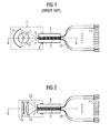
- FIG. 1 shows the operating principle of an incandescent light guide illustrated in the prior art.
- Optical fiber indicators are used in railway signaling technology Signaling of symbols, numbers, letters and any other characters. That of a filament 1 of the light bulb 2 emitted light is using a concave mirror 3 in focused on a focal point or a focal surface F. In the area the focal surface F is the light entrance surface 4 of a Fiber optic bundle 5 is arranged, wherein the light entry surface 4 is illuminated as completely and evenly as possible.
- the individual optical fibers of the optical fiber bundle 5 are layered and glued in a guide sleeve 6. To the Light efficiency does not unnecessarily reduce, the light entrance surface 4 of the optical fiber bundle 5 then ground and polished.
- a housing 7 for the bulb 2 and the concave mirror 3 is provided with a receptacle 8 for the guide sleeve 6 provided.
- a receptacle 8 for the guide sleeve 6 provided.
- an adjustment is sought, at the filament 1, the concave mirror 3 and the optical fiber bundle 5 are arranged on the optical axis 9 and the Image of the filament 1, the light entry surface 4 of the optical fiber bundle 5 illuminates exactly.
- the light guides 10 of Fiber optic bundles 5 are light exit side and outside the guide sleeve 6 is provided with light exit lenses 10, by which by means not shown controls Display for displaying letters, numbers and other symbols is filled out almost flat.
- the housing assembly 12 includes the LED module 13 with converging lens 14 and the receptacle 8 for the guide sleeve 6 of the optical fiber bundle 5 in a constructive Unit.
- the receptacle 8 for the guide sleeve 9 thus forms the corresponding prior art according to FIG Mounting point between the new housing assembly 12 and the old optical fiber assembly 5, 6, 10, 11th
- the invention is not limited to the above Embodiment. Rather, it is a number of variants conceivable, which also with fundamentally different kind Execution of the features of the invention make use.
Landscapes
- Physics & Mathematics (AREA)
- Engineering & Computer Science (AREA)
- General Physics & Mathematics (AREA)
- Mechanical Engineering (AREA)
- Optics & Photonics (AREA)
- Theoretical Computer Science (AREA)
- Non-Portable Lighting Devices Or Systems Thereof (AREA)
- Illuminated Signs And Luminous Advertising (AREA)
- Farming Of Fish And Shellfish (AREA)
- Bidet-Like Cleaning Device And Other Flush Toilet Accessories (AREA)
- Extrusion Moulding Of Plastics Or The Like (AREA)
- Light Guides In General And Applications Therefor (AREA)
- Road Signs Or Road Markings (AREA)
- Devices For Indicating Variable Information By Combining Individual Elements (AREA)
Abstract
Description
Die Erfindung betrifft einen Lichtleiteranzeiger gemäß dem Oberbegriff des Anspruchs 1.The invention relates to an optical waveguide indicator according to the Preamble of claim 1.
Die nachstehenden Erläuterungen beziehen sich im Wesentlichen auf Lichtleiteranzeiger zur Signalisierung von Symbolen, Ziffern, Buchstaben und beliebigen anderen Zeichen bei schienengebundenen Verkehrswegen, ohne dass der beanspruchte erfinderische Gegenstand auf diese Anwendung beschränkt sein soll.The following explanations essentially relate on optical fiber indicator for signaling symbols, numbers, Letters and any other signs in railbound Traffic routes without the claimed inventive Subject should be limited to this application.
Bei bekannten Lichtleiteranzeigern wird als Leuchtmittel überwiegend eine Glühlampe verwendet, deren Licht mittels eines Hohlspiegels in eine definierte Brennfläche gerichtet wird. In dieser Brennfläche befindet sich die Lichteintrittsfläche eines Lichtleiterbündels. Um die Lichtverluste in Grenzen zu halten, muss diese Lichteintrittsfläche zur Gänze und möglichst gleichmäßig beleuchtet werden. Außerdem muss die Lichteintrittsfläche mittels Schleifen und Polieren aufwändig präpariert werden.In known light guide indicators is used as a light source mainly uses an incandescent lamp, whose light by means of directed a concave mirror in a defined focal surface becomes. In this focal surface is the light entry surface a fiber optic bundle. To reduce the light losses in To keep limits, this light entry surface must be completely and be illuminated as evenly as possible. In addition, must the light entry surface by grinding and polishing consuming to be prepared.
Mit der Einführung neuartiger Leuchtmittel, insbesondere auf der Basis von LED (lichtimitierende Dioden) ergibt sich zunehmend die Notwendigkeit, Glühlampen durch moderndere Leuchtmittel zu ersetzen. Problematisch dabei ist vor allem die optische Anpassung, da die vorhandene Lichtleiterbaugruppe auf die spezielle Leuchtstärke und Abstrahlcharakteristik der Glühlampe in Verbindung mit einem Optikelement, insbesondere einem Hohlspiegel, abgestimmt ist. Moderne Leuchtmittel besitzen eine gänzlich andere Leuchtstärke und Abstrahlcharakteristik, so dass der bloße Ersatz der Glühlampe, beispielsweise durch eine LED-Anordnung, mit Lichtverlusten an der Lichteintrittsfläche des Lichtleiterbündels verbunden ist. Um gleichwertige optische Eigenschaften des Lichtleiteranzeigers zu gewährleisten, muss daher in der Regel das komplette optische System samt Lichtleiterbaugruppe neu entwickelt werden.With the introduction of novel bulbs, in particular on The basis of LED (light-emitting diodes) is increasingly evident the need to light bulbs by more modern To replace bulbs. The main problem is that the optical adjustment, since the existing fiber optic assembly on the special luminosity and radiation characteristics the light bulb in conjunction with an optical element, in particular a concave mirror is tuned. modern Bulbs have a completely different brightness and Radiation characteristic, so that the mere replacement of the light bulb, for example, by an LED arrangement, with light losses at the light entrance surface of the optical fiber bundle connected is. To obtain equivalent optical properties of As a rule, it is therefore necessary to ensure the optical waveguide the complete optical system including the optical fiber assembly be redeveloped.
Der Erfindung liegt deshalb die Aufgabe zugrunde, einen Lichtleiteranzeiger der gattungsgemäßen Art anzugeben, der für Leuchtmittel unterschiedlicher Art die Weiterverwendung der vorhandenen Lichtleiterbaugruppe ermöglicht.The invention is therefore based on the object, a Specify light guide indicator of the generic type, the for bulbs of different types the re-use allows the existing optical fiber assembly.
Erfindungsgemäß wird die Aufgabe mit den kennzeichnenden Merkmalen des Anspruchs 1 gelöst. Die Umrüstung von Glühlampen-Lichtleiteranzeigern in LED-Lichtleiteranzeigern ist auf diese Weise besonders einfach, wobei die Anpassung quasi nur von der Beleuchtungsseite her vorgenommen wird und die Lichtleiterbaugruppe weiterverwendet werden kann. Bekannte LED-Module bestehen im Wesentlichen aus einer rasterartigen Anordnung mehrerer LED, welche jeweils mit einem Reflektor ausgestattet sind, wobei ein lichtbündelndes optisches Element gemäß Anspruch 3 und gegebenenfalls eine Frontscheibe vorgesehen sind. Erfindungsgemäß wird somit lediglich eine optische Anpassung an die bewährte Lichtleiterbaugruppe vorgenommen. Vorzugsweise sind die einzelnen LED des LED-Moduls derart verschaltet, dass ein Sicherheitskonzept bezüglich LED-Ausfall realisierbar ist.According to the invention the task with the characterizing Characteristics of claim 1 solved. The conversion of incandescent light guide indicators in LED light guide is on this way very simple, with the adjustment almost only is made from the lighting side and the optical fiber assembly can be used. Well-known LED modules consist essentially of a grid-like arrangement several LEDs, each equipped with a reflector are, wherein a light-bundling optical element according to Claim 3 and optionally provided a windshield are. According to the invention thus only an optical Adapted to the proven fiber optic assembly. Preferably, the individual LEDs of the LED module are such that interconnects a safety concept regarding LED failure is feasible.
Gemäß Anspruch 2 ist das Lichtleiterbündel in einer Führungshülse angeordnet, welche in einer Aufnahme eines Gehäuses für das LED-Modul einschiebbar und justierbar ist. Auf diese Weise kann die optimale Lichtverteilung und Helligkeit auf einem Display des Lichtleiteranzeigers eingestellt werden. According to claim 2, the optical fiber bundle is in a guide sleeve arranged, which in a receptacle of a housing for The LED module is insertable and adjustable. To this Way, the optimal light distribution and brightness can be up a display of the light guide indicator can be set.
Als moderne Leuchtmittel, die für den Glühlampenersatz infrage kommen, können gemäß Anspruch 4 auch flächige Leuchtelemente, beispielsweise auf der Basis organischer LED, vorgesehen sein. Die Leuchtfläche des flächigen Leuchtelementes kann dann an die Lichteintrittsfläche des Lichtleiterbündels unmittelbar angepasst werden. Denkbar ist aber auch die Zwischenschaltung einer, insbesondere bündelnden, Optik.As modern bulbs, the question for the bulb replacement come, can according to claim 4 and flat lighting elements, for example, based on organic LED provided be. The luminous surface of the planar luminous element can then contact the light entrance surface of the optical fiber bundle be adjusted immediately. It is also conceivable, however, the interposition a, in particular bundling, optics.
Nahfolgend wird die Erfindung anhand figürlicher Darstellungen
näher erläutert. Es zeigen:
In Figur 1 ist das Funktionsprinzip eines Glühlampen-Lichtleiteranzeigers
nach dem Stand der Technik veranschaulicht.
Lichtleiteranzeiger dienen in der Eisenbahnsignaltechnik zur
Signalisierung von Symbolen, Ziffern, Buchstaben und beliebigen
anderen Zeichen. Das von einer Glühwendel 1 der Glühlampe
2 emittierte Licht wird mit Hilfe eines Hohlspiegels 3 in
einem Brennpunkt bzw. einer Brennfläche F fokussiert. Im Bereich
der Brennfläche F ist die Lichteintrittsfläche 4 eines
Lichtleiterbündels 5 angeordnet, wobei die Lichteintrittsfläche
4 möglichst vollständig und gleichmäßig beleuchtet wird.
Die einzelnen Lichtleiter des Lichtleiterbündels 5 werden geschichtet
und in einer Führungshülse 6 verklebt. Um die
Lichtausbeute nicht unnötig zu verringern, wird die Lichteintrittsfläche
4 des Lichtleiterbündels 5 anschließend geschliffen
und poliert. Ein Gehäuse 7 für die Glühlampe 2 und
den Hohlspiegel 3 ist mit einer Aufnahme 8 für die Führungshülse
6 versehen. Dabei wird eine Justierung angestrebt, bei
der die Glühwendel 1, der Hohlspiegel 3 und das Lichtleiterbündel
5 auf der optischen Achse 9 angeordnet sind und das
Abbild der Glühwendel 1 die Lichteintrittsfläche 4 des Lichtleiterbündels
5 exakt ausleuchtet. Die Lichtleiter 10 des
Lichtleiterbündels 5 sind lichtaustrittsseitig und außerhalb
der Führungshülse 6 mit Lichtaustrittslinsen 10 versehen,
durch welche mittels nicht dargestellter Steuerelemente ein
Display zur Anzeige von Buchstaben, Zahlen und andern Symbolen
quasi flächig ausgefüllt wird.FIG. 1 shows the operating principle of an incandescent light guide
illustrated in the prior art.
Optical fiber indicators are used in railway signaling technology
Signaling of symbols, numbers, letters and any
other characters. That of a filament 1 of the light bulb
2 emitted light is using a concave mirror 3 in
focused on a focal point or a focal surface F. In the area
the focal surface F is the light entrance surface 4 of a
Fiber
Um diese hochwertige und bewährte Lichtleiterbaugruppe auch
für andere Leuchtmittel anstelle der Glühwendel 1 verwenden
zu können, ist eine Gehäusebaugruppe 12 mit einem LED-Modul
13 samt vorgeschalteter Sammellinse 14 zur Fokussierung des
LED-Lichtes in die Brennebene F vorgesehen, wie aus Figur 2
ersichtlich. Auf diese Weise wird die Lichteintrittsfläche 4
des Lichtleiterbündels 5 quasi mit einem glühwendelartigen
Lichtfleck beleuchtet. Die Gehäusebaugruppe 12 umfasst dabei
das LED-Modul 13 mit Sammellinse 14 und die Aufnahme 8 für
die Führungshülse 6 des Lichtleiterbündels 5 in einer konstruktiven
Einheit. Die Aufnahme 8 für die Führungshülse 9
bildet mithin die dem Stand der Technik gemäß Figur 1 entsprechende
Befestigungsstelle zwischen der neuen Gehäusebaugruppe
12 und der alten Lichtleiterbaugruppe 5, 6, 10, 11.To this high-quality and proven light guide assembly too
for other bulbs instead of filament 1 use
to be able to, is a
Die Erfindung beschränkt sich nicht auf das vorstehend angegebene Ausführungsbeispiel. Vielmehr ist eine Anzahl von Varianten denkbar, welche auch bei grundsätzlich anders gearteter Ausführung von den Merkmalen der Erfindung Gebrauch machen.The invention is not limited to the above Embodiment. Rather, it is a number of variants conceivable, which also with fundamentally different kind Execution of the features of the invention make use.
Claims (4)
dadurch gekennzeichnet, dass das Leuchtmittel und das Optikelement als LED-Modul (13) ausgebildet sind.Optical waveguide with a luminous means and an optical element for focusing the light emitted by the illuminant light in a focal surface (F) whose arrangement, size and geometry substantially with the arrangement, size and geometry of a light entrance surface (4) of an optical fiber bundle (5) matches, in particular for the signaling of symbols and signs in rail-bound traffic routes,
characterized in that the lighting means and the optical element as LED module (13) are formed.
dadurch gekennzeichnet, dass das Lichtleiterbündel (5) in einer Führungshülse (6) angeordnet ist, wobei ein Gehäuse (12) für das LED-Modul (13) und eine Aufnahme (8) für die Führungshülse (6) eine konstruktive Einheit bilden.Optical waveguide indicator according to claim 1,
characterized in that the optical fiber bundle (5) in a guide sleeve (6) is arranged, wherein a housing (12) for the LED module (13) and a receptacle (8) for the guide sleeve (6) form a structural unit.
dadurch gekennzeichnet, dass das Optikelement als Sammellinse (14) oder Fresnelplatte ausgebildet ist.Optical waveguide indicator according to one of the preceding claims,
characterized in that the optical element is designed as a converging lens (14) or Fresnel plate.
dadurch gekennzeichnet, dass das LED-Modul auf der Basis organischer LED, deren Leuchtfläche mit der Größe und der Geometrie der Brennfläche (F) im Wesentliche übereinstimmt, ausgebildet ist.Optical waveguide indicator according to claim 1 or 2,
characterized in that the LED module on the basis of organic LED, whose luminous area with the size and the geometry of the focal surface (F) substantially matches, is formed.
Applications Claiming Priority (2)
| Application Number | Priority Date | Filing Date | Title |
|---|---|---|---|
| DE102004014417 | 2004-03-18 | ||
| DE102004014417A DE102004014417A1 (en) | 2004-03-18 | 2004-03-18 | Optical fiber Gazette |
Publications (3)
| Publication Number | Publication Date |
|---|---|
| EP1577863A2 true EP1577863A2 (en) | 2005-09-21 |
| EP1577863A3 EP1577863A3 (en) | 2006-05-10 |
| EP1577863B1 EP1577863B1 (en) | 2011-10-12 |
Family
ID=34833240
Family Applications (1)
| Application Number | Title | Priority Date | Filing Date |
|---|---|---|---|
| EP05090034A Not-in-force EP1577863B1 (en) | 2004-03-18 | 2005-02-18 | Display device with optical fibers |
Country Status (5)
| Country | Link |
|---|---|
| EP (1) | EP1577863B1 (en) |
| AT (1) | ATE528743T1 (en) |
| DE (1) | DE102004014417A1 (en) |
| ES (1) | ES2372498T3 (en) |
| NO (1) | NO330748B1 (en) |
Cited By (3)
| Publication number | Priority date | Publication date | Assignee | Title |
|---|---|---|---|---|
| FR2898722A1 (en) * | 2006-03-16 | 2007-09-21 | Colas Sa | Highway sign displaying device for signal panel, has fiber bundle with input face corresponding to common part regrouping fibers enlightened by LED whose surface is small, and adaptation device disposed between diode and input face |
| EP2708803A1 (en) * | 2012-09-14 | 2014-03-19 | Thales Deutschland GmbH | Universal traffic light luminaire |
| DE102013212906A1 (en) | 2013-07-02 | 2014-07-10 | Siemens Aktiengesellschaft | Signal generator of e.g. LED light signals used in road traffic sector, has optical waveguide element for mixing color components of different colored LEDs, having curved area with a portion comprised of longitudinally extending groove |
Citations (3)
| Publication number | Priority date | Publication date | Assignee | Title |
|---|---|---|---|---|
| DE2613912A1 (en) * | 1976-03-31 | 1977-10-13 | Siemens Ag | Light signal generator with several light emitters - has light sources with collector lenses of short focal length arranged side by side |
| DE4003846A1 (en) * | 1989-02-10 | 1990-08-16 | Zelisko Josef Elektro Masch | Holder for optical fibre bunch - with wedge-type entry exerting radial clamping forces on bunch |
| DE19953542A1 (en) * | 1998-11-12 | 2000-05-18 | Fabema Funkampeldienst Manfred | Lamp unit for mobile traffic lights |
-
2004
- 2004-03-18 DE DE102004014417A patent/DE102004014417A1/en not_active Ceased
-
2005
- 2005-02-18 ES ES05090034T patent/ES2372498T3/en active Active
- 2005-02-18 EP EP05090034A patent/EP1577863B1/en not_active Not-in-force
- 2005-02-18 AT AT05090034T patent/ATE528743T1/en active
- 2005-03-18 NO NO20051425A patent/NO330748B1/en not_active IP Right Cessation
Patent Citations (3)
| Publication number | Priority date | Publication date | Assignee | Title |
|---|---|---|---|---|
| DE2613912A1 (en) * | 1976-03-31 | 1977-10-13 | Siemens Ag | Light signal generator with several light emitters - has light sources with collector lenses of short focal length arranged side by side |
| DE4003846A1 (en) * | 1989-02-10 | 1990-08-16 | Zelisko Josef Elektro Masch | Holder for optical fibre bunch - with wedge-type entry exerting radial clamping forces on bunch |
| DE19953542A1 (en) * | 1998-11-12 | 2000-05-18 | Fabema Funkampeldienst Manfred | Lamp unit for mobile traffic lights |
Cited By (5)
| Publication number | Priority date | Publication date | Assignee | Title |
|---|---|---|---|---|
| FR2898722A1 (en) * | 2006-03-16 | 2007-09-21 | Colas Sa | Highway sign displaying device for signal panel, has fiber bundle with input face corresponding to common part regrouping fibers enlightened by LED whose surface is small, and adaptation device disposed between diode and input face |
| EP2708803A1 (en) * | 2012-09-14 | 2014-03-19 | Thales Deutschland GmbH | Universal traffic light luminaire |
| WO2014041099A3 (en) * | 2012-09-14 | 2014-05-08 | Thales Deutschland Gmbh | Universal traffic light luminaire |
| US9599763B2 (en) | 2012-09-14 | 2017-03-21 | Thales Deutschland Gmbh | Universal traffic light luminaire |
| DE102013212906A1 (en) | 2013-07-02 | 2014-07-10 | Siemens Aktiengesellschaft | Signal generator of e.g. LED light signals used in road traffic sector, has optical waveguide element for mixing color components of different colored LEDs, having curved area with a portion comprised of longitudinally extending groove |
Also Published As
| Publication number | Publication date |
|---|---|
| NO20051425L (en) | 2005-09-19 |
| EP1577863A3 (en) | 2006-05-10 |
| DE102004014417A1 (en) | 2005-10-13 |
| ATE528743T1 (en) | 2011-10-15 |
| EP1577863B1 (en) | 2011-10-12 |
| NO20051425D0 (en) | 2005-03-18 |
| ES2372498T3 (en) | 2012-01-20 |
| NO330748B1 (en) | 2011-07-04 |
Similar Documents
| Publication | Publication Date | Title |
|---|---|---|
| DE10034594B4 (en) | Dental treatment light | |
| WO2014114417A1 (en) | Light-source assembly for motor vehicle headlamps | |
| DE102017114948A1 (en) | Light emitting means | |
| DE102009048830B4 (en) | Lichtleitstruktur | |
| EP1538059B1 (en) | Light signal | |
| DE102013021357A1 (en) | Luminaire with light guide | |
| DE102014116983B4 (en) | LASER OPTICAL SYSTEM FOR A VEHICLE HEADLIGHT IN WHICH A BEAM LENS FOCUSING A LASER BEAM IS IN DIRECT CONTACT WITH A LUMINOUS BODY EXCITED BY THE LASER BEAM | |
| DE20014114U1 (en) | Illuminating or lighting device with Fresnel optics | |
| EP1577863B1 (en) | Display device with optical fibers | |
| EP2113712A1 (en) | Light signal | |
| EP1201985A2 (en) | Lighting system, in particular for motor vehicles and method of generating a light beam having a predetermined shape | |
| DE202009016976U1 (en) | Light source, headlight of a means of transport and optical system of the light source | |
| DE202009002499U1 (en) | LED street light with fiber optic reflector extractor system | |
| EP3473918B1 (en) | Lighting device for a motor vehicle headlight | |
| DE102006041085A1 (en) | Advertising medium e.g. advertising pillar has advertising surface and a lighting system whereby lighting system is fiber optic cable based lighting system with a light outlet | |
| DE102012201706A1 (en) | Operating light has multiple light emitting diodes for determining illumination of operating field and secondary reflector, which directs light emitted by light emitting diode on to operation field | |
| DE102020130848A1 (en) | Light emitting device | |
| DE102020100552A1 (en) | Light with a brake light function and a tail light function | |
| DE102012218785A1 (en) | LAMP | |
| DE2240779A1 (en) | SIGNAL LAMP DEVICE IN TRAFFIC SIGNAL SYSTEMS | |
| DE19640325A1 (en) | High power hollow light conductor arrangement | |
| DE102015001694A1 (en) | Lighting device for a headlight of a motor vehicle and method for operating a lighting device | |
| EP2246612B1 (en) | LED lamp | |
| DE102008022346A1 (en) | light signal | |
| AT509536B1 (en) | FIBER OPTIC ILLUMINATION DEVICE |
Legal Events
| Date | Code | Title | Description |
|---|---|---|---|
| PUAI | Public reference made under article 153(3) epc to a published international application that has entered the european phase |
Free format text: ORIGINAL CODE: 0009012 |
|
| AK | Designated contracting states |
Kind code of ref document: A2 Designated state(s): AT BE BG CH CY CZ DE DK EE ES FI FR GB GR HU IE IS IT LI LT LU MC NL PL PT RO SE SI SK TR |
|
| AX | Request for extension of the european patent |
Extension state: AL BA HR LV MK YU |
|
| PUAL | Search report despatched |
Free format text: ORIGINAL CODE: 0009013 |
|
| AK | Designated contracting states |
Kind code of ref document: A3 Designated state(s): AT BE BG CH CY CZ DE DK EE ES FI FR GB GR HU IE IS IT LI LT LU MC NL PL PT RO SE SI SK TR |
|
| AX | Request for extension of the european patent |
Extension state: AL BA HR LV MK YU |
|
| RIC1 | Information provided on ipc code assigned before grant |
Ipc: G08G 1/095 20060101ALI20060322BHEP Ipc: G09F 9/305 20060101AFI20050628BHEP |
|
| 17P | Request for examination filed |
Effective date: 20060619 |
|
| AKX | Designation fees paid |
Designated state(s): AT BE BG CH CY CZ DE DK EE ES FI FR GB GR HU IE IS IT LI LT LU MC NL PL PT RO SE SI SK TR |
|
| GRAP | Despatch of communication of intention to grant a patent |
Free format text: ORIGINAL CODE: EPIDOSNIGR1 |
|
| GRAS | Grant fee paid |
Free format text: ORIGINAL CODE: EPIDOSNIGR3 |
|
| GRAA | (expected) grant |
Free format text: ORIGINAL CODE: 0009210 |
|
| AK | Designated contracting states |
Kind code of ref document: B1 Designated state(s): AT BE BG CH CY CZ DE DK EE ES FI FR GB GR HU IE IS IT LI LT LU MC NL PL PT RO SE SI SK TR |
|
| REG | Reference to a national code |
Ref country code: GB Ref legal event code: FG4D Free format text: NOT ENGLISH |
|
| REG | Reference to a national code |
Ref country code: CH Ref legal event code: NV Representative=s name: SIEMENS SCHWEIZ AG Ref country code: CH Ref legal event code: EP |
|
| REG | Reference to a national code |
Ref country code: IE Ref legal event code: FG4D |
|
| REG | Reference to a national code |
Ref country code: DE Ref legal event code: R096 Ref document number: 502005012003 Country of ref document: DE Effective date: 20111208 |
|
| REG | Reference to a national code |
Ref country code: NL Ref legal event code: T3 |
|
| REG | Reference to a national code |
Ref country code: ES Ref legal event code: FG2A Ref document number: 2372498 Country of ref document: ES Kind code of ref document: T3 Effective date: 20120120 |
|
| LTIE | Lt: invalidation of european patent or patent extension |
Effective date: 20111012 |
|
| PG25 | Lapsed in a contracting state [announced via postgrant information from national office to epo] |
Ref country code: IS Free format text: LAPSE BECAUSE OF FAILURE TO SUBMIT A TRANSLATION OF THE DESCRIPTION OR TO PAY THE FEE WITHIN THE PRESCRIBED TIME-LIMIT Effective date: 20120212 Ref country code: LT Free format text: LAPSE BECAUSE OF FAILURE TO SUBMIT A TRANSLATION OF THE DESCRIPTION OR TO PAY THE FEE WITHIN THE PRESCRIBED TIME-LIMIT Effective date: 20111012 |
|
| REG | Reference to a national code |
Ref country code: IE Ref legal event code: FD4D |
|
| PG25 | Lapsed in a contracting state [announced via postgrant information from national office to epo] |
Ref country code: SE Free format text: LAPSE BECAUSE OF FAILURE TO SUBMIT A TRANSLATION OF THE DESCRIPTION OR TO PAY THE FEE WITHIN THE PRESCRIBED TIME-LIMIT Effective date: 20111012 Ref country code: GR Free format text: LAPSE BECAUSE OF FAILURE TO SUBMIT A TRANSLATION OF THE DESCRIPTION OR TO PAY THE FEE WITHIN THE PRESCRIBED TIME-LIMIT Effective date: 20120113 Ref country code: PT Free format text: LAPSE BECAUSE OF FAILURE TO SUBMIT A TRANSLATION OF THE DESCRIPTION OR TO PAY THE FEE WITHIN THE PRESCRIBED TIME-LIMIT Effective date: 20120213 Ref country code: SI Free format text: LAPSE BECAUSE OF FAILURE TO SUBMIT A TRANSLATION OF THE DESCRIPTION OR TO PAY THE FEE WITHIN THE PRESCRIBED TIME-LIMIT Effective date: 20111012 |
|
| PG25 | Lapsed in a contracting state [announced via postgrant information from national office to epo] |
Ref country code: CY Free format text: LAPSE BECAUSE OF FAILURE TO SUBMIT A TRANSLATION OF THE DESCRIPTION OR TO PAY THE FEE WITHIN THE PRESCRIBED TIME-LIMIT Effective date: 20111012 |
|
| PG25 | Lapsed in a contracting state [announced via postgrant information from national office to epo] |
Ref country code: SK Free format text: LAPSE BECAUSE OF FAILURE TO SUBMIT A TRANSLATION OF THE DESCRIPTION OR TO PAY THE FEE WITHIN THE PRESCRIBED TIME-LIMIT Effective date: 20111012 Ref country code: DK Free format text: LAPSE BECAUSE OF FAILURE TO SUBMIT A TRANSLATION OF THE DESCRIPTION OR TO PAY THE FEE WITHIN THE PRESCRIBED TIME-LIMIT Effective date: 20111012 Ref country code: EE Free format text: LAPSE BECAUSE OF FAILURE TO SUBMIT A TRANSLATION OF THE DESCRIPTION OR TO PAY THE FEE WITHIN THE PRESCRIBED TIME-LIMIT Effective date: 20111012 Ref country code: BG Free format text: LAPSE BECAUSE OF FAILURE TO SUBMIT A TRANSLATION OF THE DESCRIPTION OR TO PAY THE FEE WITHIN THE PRESCRIBED TIME-LIMIT Effective date: 20120112 Ref country code: CZ Free format text: LAPSE BECAUSE OF FAILURE TO SUBMIT A TRANSLATION OF THE DESCRIPTION OR TO PAY THE FEE WITHIN THE PRESCRIBED TIME-LIMIT Effective date: 20111012 Ref country code: IE Free format text: LAPSE BECAUSE OF FAILURE TO SUBMIT A TRANSLATION OF THE DESCRIPTION OR TO PAY THE FEE WITHIN THE PRESCRIBED TIME-LIMIT Effective date: 20111012 |
|
| PLBE | No opposition filed within time limit |
Free format text: ORIGINAL CODE: 0009261 |
|
| STAA | Information on the status of an ep patent application or granted ep patent |
Free format text: STATUS: NO OPPOSITION FILED WITHIN TIME LIMIT |
|
| PG25 | Lapsed in a contracting state [announced via postgrant information from national office to epo] |
Ref country code: IT Free format text: LAPSE BECAUSE OF FAILURE TO SUBMIT A TRANSLATION OF THE DESCRIPTION OR TO PAY THE FEE WITHIN THE PRESCRIBED TIME-LIMIT Effective date: 20111012 Ref country code: PL Free format text: LAPSE BECAUSE OF FAILURE TO SUBMIT A TRANSLATION OF THE DESCRIPTION OR TO PAY THE FEE WITHIN THE PRESCRIBED TIME-LIMIT Effective date: 20111012 Ref country code: RO Free format text: LAPSE BECAUSE OF FAILURE TO SUBMIT A TRANSLATION OF THE DESCRIPTION OR TO PAY THE FEE WITHIN THE PRESCRIBED TIME-LIMIT Effective date: 20111012 |
|
| 26N | No opposition filed |
Effective date: 20120713 |
|
| PG25 | Lapsed in a contracting state [announced via postgrant information from national office to epo] |
Ref country code: MC Free format text: LAPSE BECAUSE OF NON-PAYMENT OF DUE FEES Effective date: 20120229 |
|
| REG | Reference to a national code |
Ref country code: DE Ref legal event code: R097 Ref document number: 502005012003 Country of ref document: DE Effective date: 20120713 |
|
| PGFP | Annual fee paid to national office [announced via postgrant information from national office to epo] |
Ref country code: ES Payment date: 20130307 Year of fee payment: 9 Ref country code: FR Payment date: 20130301 Year of fee payment: 9 |
|
| PGFP | Annual fee paid to national office [announced via postgrant information from national office to epo] |
Ref country code: NL Payment date: 20130204 Year of fee payment: 9 |
|
| PG25 | Lapsed in a contracting state [announced via postgrant information from national office to epo] |
Ref country code: FI Free format text: LAPSE BECAUSE OF FAILURE TO SUBMIT A TRANSLATION OF THE DESCRIPTION OR TO PAY THE FEE WITHIN THE PRESCRIBED TIME-LIMIT Effective date: 20111012 |
|
| PGFP | Annual fee paid to national office [announced via postgrant information from national office to epo] |
Ref country code: BE Payment date: 20130312 Year of fee payment: 9 |
|
| PG25 | Lapsed in a contracting state [announced via postgrant information from national office to epo] |
Ref country code: TR Free format text: LAPSE BECAUSE OF FAILURE TO SUBMIT A TRANSLATION OF THE DESCRIPTION OR TO PAY THE FEE WITHIN THE PRESCRIBED TIME-LIMIT Effective date: 20111012 |
|
| PG25 | Lapsed in a contracting state [announced via postgrant information from national office to epo] |
Ref country code: LU Free format text: LAPSE BECAUSE OF NON-PAYMENT OF DUE FEES Effective date: 20120218 |
|
| PGFP | Annual fee paid to national office [announced via postgrant information from national office to epo] |
Ref country code: GB Payment date: 20140210 Year of fee payment: 10 |
|
| PG25 | Lapsed in a contracting state [announced via postgrant information from national office to epo] |
Ref country code: HU Free format text: LAPSE BECAUSE OF FAILURE TO SUBMIT A TRANSLATION OF THE DESCRIPTION OR TO PAY THE FEE WITHIN THE PRESCRIBED TIME-LIMIT Effective date: 20050218 |
|
| BERE | Be: lapsed |
Owner name: SIEMENS A.G. Effective date: 20140228 |
|
| REG | Reference to a national code |
Ref country code: NL Ref legal event code: V1 Effective date: 20140901 |
|
| PG25 | Lapsed in a contracting state [announced via postgrant information from national office to epo] |
Ref country code: NL Free format text: LAPSE BECAUSE OF NON-PAYMENT OF DUE FEES Effective date: 20140901 |
|
| REG | Reference to a national code |
Ref country code: FR Ref legal event code: ST Effective date: 20141031 |
|
| PG25 | Lapsed in a contracting state [announced via postgrant information from national office to epo] |
Ref country code: BE Free format text: LAPSE BECAUSE OF NON-PAYMENT OF DUE FEES Effective date: 20140228 Ref country code: FR Free format text: LAPSE BECAUSE OF NON-PAYMENT OF DUE FEES Effective date: 20140228 |
|
| REG | Reference to a national code |
Ref country code: ES Ref legal event code: FD2A Effective date: 20150702 |
|
| PG25 | Lapsed in a contracting state [announced via postgrant information from national office to epo] |
Ref country code: ES Free format text: LAPSE BECAUSE OF NON-PAYMENT OF DUE FEES Effective date: 20140219 |
|
| GBPC | Gb: european patent ceased through non-payment of renewal fee |
Effective date: 20150218 |
|
| PG25 | Lapsed in a contracting state [announced via postgrant information from national office to epo] |
Ref country code: GB Free format text: LAPSE BECAUSE OF NON-PAYMENT OF DUE FEES Effective date: 20150218 |
|
| REG | Reference to a national code |
Ref country code: CH Ref legal event code: PCOW Free format text: NEW ADDRESS: WERNER-VON-SIEMENS-STRASSE 1, 80333 MUENCHEN (DE) |
|
| PGFP | Annual fee paid to national office [announced via postgrant information from national office to epo] |
Ref country code: AT Payment date: 20180104 Year of fee payment: 14 |
|
| PGFP | Annual fee paid to national office [announced via postgrant information from national office to epo] |
Ref country code: CH Payment date: 20180516 Year of fee payment: 14 Ref country code: DE Payment date: 20180419 Year of fee payment: 14 |
|
| REG | Reference to a national code |
Ref country code: DE Ref legal event code: R119 Ref document number: 502005012003 Country of ref document: DE |
|
| REG | Reference to a national code |
Ref country code: CH Ref legal event code: PL |
|
| REG | Reference to a national code |
Ref country code: AT Ref legal event code: MM01 Ref document number: 528743 Country of ref document: AT Kind code of ref document: T Effective date: 20190218 |
|
| PG25 | Lapsed in a contracting state [announced via postgrant information from national office to epo] |
Ref country code: LI Free format text: LAPSE BECAUSE OF NON-PAYMENT OF DUE FEES Effective date: 20190228 Ref country code: AT Free format text: LAPSE BECAUSE OF NON-PAYMENT OF DUE FEES Effective date: 20190218 Ref country code: CH Free format text: LAPSE BECAUSE OF NON-PAYMENT OF DUE FEES Effective date: 20190228 |
|
| PG25 | Lapsed in a contracting state [announced via postgrant information from national office to epo] |
Ref country code: DE Free format text: LAPSE BECAUSE OF NON-PAYMENT OF DUE FEES Effective date: 20190903 |