EP1577508B1 - Valve return device motor provided with such a device - Google Patents
Valve return device motor provided with such a device Download PDFInfo
- Publication number
- EP1577508B1 EP1577508B1 EP05290548A EP05290548A EP1577508B1 EP 1577508 B1 EP1577508 B1 EP 1577508B1 EP 05290548 A EP05290548 A EP 05290548A EP 05290548 A EP05290548 A EP 05290548A EP 1577508 B1 EP1577508 B1 EP 1577508B1
- Authority
- EP
- European Patent Office
- Prior art keywords
- pressure
- valve
- feed
- cylinder
- return
- Prior art date
- Legal status (The legal status is an assumption and is not a legal conclusion. Google has not performed a legal analysis and makes no representation as to the accuracy of the status listed.)
- Expired - Lifetime
Links
- 239000012530 fluid Substances 0.000 claims description 19
- 238000002485 combustion reaction Methods 0.000 claims description 9
- PXFBZOLANLWPMH-UHFFFAOYSA-N 16-Epiaffinine Natural products C1C(C2=CC=CC=C2N2)=C2C(=O)CC2C(=CC)CN(C)C1C2CO PXFBZOLANLWPMH-UHFFFAOYSA-N 0.000 claims description 6
- 238000011144 upstream manufacturing Methods 0.000 claims description 4
- 230000001105 regulatory effect Effects 0.000 claims description 3
- 238000010586 diagram Methods 0.000 description 15
- 230000033228 biological regulation Effects 0.000 description 9
- 230000009471 action Effects 0.000 description 4
- 230000009257 reactivity Effects 0.000 description 3
- 240000008042 Zea mays Species 0.000 description 2
- 238000012550 audit Methods 0.000 description 2
- 238000006073 displacement reaction Methods 0.000 description 2
- 230000003416 augmentation Effects 0.000 description 1
- 230000006835 compression Effects 0.000 description 1
- 238000007906 compression Methods 0.000 description 1
- 230000001627 detrimental effect Effects 0.000 description 1
- 230000000694 effects Effects 0.000 description 1
- 230000000977 initiatory effect Effects 0.000 description 1
- 230000002028 premature Effects 0.000 description 1
- 230000009467 reduction Effects 0.000 description 1
- 230000004044 response Effects 0.000 description 1
- 230000000284 resting effect Effects 0.000 description 1
- 230000000630 rising effect Effects 0.000 description 1
- 238000013022 venting Methods 0.000 description 1
Images


Classifications
-
- F—MECHANICAL ENGINEERING; LIGHTING; HEATING; WEAPONS; BLASTING
- F01—MACHINES OR ENGINES IN GENERAL; ENGINE PLANTS IN GENERAL; STEAM ENGINES
- F01L—CYCLICALLY OPERATING VALVES FOR MACHINES OR ENGINES
- F01L1/00—Valve-gear or valve arrangements, e.g. lift-valve gear
- F01L1/46—Component parts, details, or accessories, not provided for in preceding subgroups
- F01L1/462—Valve return spring arrangements
- F01L1/465—Pneumatic arrangements
Definitions
- the invention relates to the control of valves in internal combustion engines.
- It relates to a valve return device and an internal combustion engine equipped with such a device.
- the motors are equipped with return devices which comprise, for each valve, a spring which urges it permanently in the direction of its closure (that is to say in the direction of the cam corresponding).
- the proposed system comprises a piston integral with a valve stem and sliding in a cylinder, the piston, the valve stem and the cylinder forming a sealed chamber which encloses a compressible fluid at a predetermined minimum setting pressure corresponding to the fully closed position of the valve.
- valve control system so proposed is an advance over the system of the document FR-2 529 616, the structure used to provide pressure control is however relatively complex, while its reactivity, insufficient, is detrimental to sudden changes in engine speed.
- the invention aims in particular to overcome the aforementioned drawbacks, by proposing a return device for precise regulation of the return force to which the valve is subjected and which, while having increased reactivity (in other words a reduced response time, especially during sudden changes in engine speed), can further reduce the risk of panic valves.
- the pressure relief valve is provided with a return spring, in which case the constant P 2 is the set pressure of said pressure relief valve provided by said return spring.
- the pressure relief valve is for example connected to the supply by a bypass channel.
- non-return valve placed on the supply channel, the bypass channel being connected to the supply upstream of the non-return valve.
- the power supply can be controlled to regulate the supply pressure according to one or more determined parameters, such as the engine speed.
- the power supply is preferably controlled to increase the supply pressure as the engine speed increases.
- the invention proposes an internal combustion engine equipped with a return device as presented above.
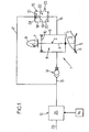
- FIG. 1 shows a return device 1 of a valve 2 of an internal combustion engine of which only the intake (or exhaust) pipe 3 has been shown, the valve 2 of which controls the opening and the closing.
- the valve 2 comprises a rod 4 which ends, at one of its ends, with a head 5 able to bear against a seat 6 which forms the mouth of the tubing of admission 3.
- the rod 4 ends, at its opposite end, with a tail 7 shaped as a cam follower which is held in abutment by a pneumatic spring 8 (described below) against a cam 9 of a camshaft whose rotation controls the opening and closing of the valve 2.
- the valve 2 is provided with a piston 10 which, secured to the valve stem 4, is slidably mounted in a cylinder 11.
- the device 1 also comprises a supply 12 of fluid under pressure, fluidly connected to the cylinder 11 by a supply channel 13 on which is placed a check valve 14.
- the device 1 further comprises a pressure relief valve 15 fluidly connected, on the one hand to the cylinder 11 by a discharge channel 16 and, on the other hand, to the supply 12 by a bypass channel 17 which, as can be seen in FIGS. 1 to 6, is connected to the supply 12 upstream of the non-return valve 14.
- the pressure relief valve 15 comprises a cylinder 18 in which slides a piston 19 which is integral with a valve 20.
- the piston 19 divides the cylinder 18 into two sealed chambers, namely a so-called overpressure chamber 21, into which the bypass channel 17, and an expansion chamber 22 in which the discharge channel 16 opens and a venting channel 23 through which the pressure in the expansion chamber 22 is constantly equal to atmospheric pressure.
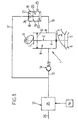
- the piston 19 is movably mounted between a so-called closing position, illustrated in FIG. 1, in which the valve 20 closes off the evacuation channel 16, and a so-called opening position, illustrated in FIG. 3, in which the valve 20 is separated from the evacuation channel 16 that it thus communicates with the expansion chamber 22.
- S P is the area of the surface of the piston 19 turned on the side of the pressure chamber 21, and S S the area of the surface of the valve 20 turned towards the side of the discharge channel 16.
- the pressure relief valve 15 is equipped with a return spring 24 which constantly urges the piston 19 to its closed position.
- the supply 12 comprises a pressure regulator connected via a channel 26 to a source of pressurized fluid (not shown), this regulator being arranged to vary the pressure in the feed channel 13 as a function of one or more determined parameters such as the engine speed, which is characterized by the rotational speed - denoted V R - of the motor shaft.
- the pressure relief valve 15 is designed to limit the pressure P prevailing in the cylinder 11 to the maximum pressure P M : indeed, when the pressure P reaches or exceeds this maximum pressure P M , the fluid of the discharge channel 16, in from the cylinder 11, exerts on the valve 20 a pressure which compensates the pressure P M prevailing in the pressure chamber 21, which tends to move the piston 19, initially in its closed position, to its open position, putting thus the evacuation channel 16 in communication with the chamber of relaxation 22.
- valve is shown at its top dead center (TDC see Figure 7) where, pressed against the seat 6, it closes the intake manifold 3.
- check valves 14 and of overpressure 15 makes it possible to limit between two extreme values (corresponding, respectively, to the minimum pressure P m and to the maximum pressure P M , the restoring force exerted on the valve 2 by the air spring 8 constituted by the fluid present in the cylinder 11.
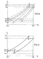
- FIG. 8 shows a diagram illustrating the pressure P of the fluid contained in the cylinder 11 as a function of the displacement h of the piston 10, illustrating three successive cycles of opening / closing of the valve 2, between which it has been controlled, first an increase in the supply pressure P A consecutive to the increase in the engine speed, then a decrease in the supply pressure P A following a decrease in engine speed.
- the pressure P is equal to the minimum pressure P m1 corresponding to the initial supply pressure P A.
- P A also corresponds to a maximum pressure P M1 , which reigns in the overpressure chamber 21.
- the opening phase of the valve 2 is as previously described (between the points A and B, curve in solid lines), the pressure relief valve 15 intervening (between points B and C) when the pressure P reaches the maximum pressure. P M1 .
- the regulator 25 controls (arbitrarily) an increase in the engine speed in the closing phase of the valve 2, corresponding to the expansion of the fluid (between the points C and D of the diagram of FIG. 8): the regulator 25 then controls the increase of the supply pressure P A.
- the air spring 8 is thus modified with respect to the previous cycle, its stiffness being greater.
- the opening phase of the valve is as described above (points B 'and C', dotted line).
- a reduction of the engine speed is controlled (arbitrarily): the regulator 25 then controls a decrease in the supply pressure P A , the the minimum pressure is then established at a new value P m3 while the maximum pressure prevailing in the booster chamber 21 is set at a new value P M3 , these new values P m3 and P M3 being, respectively, less than initial values P m1 and P M1 .
- the opening phase of the valve 2 is then repeated as before (between the points A “and B”, then between the points B “and C”, curve in phantom), the air spring 8 however having a stiffness less than the stiffness that it presented during the two previous cycles;
- the regulator 25 then controls an increase in the supply pressure P A , the minimum and maximum pressures then returning to their respective initial values P m1 and P M1 .
- the rotation of the cam 9 causes, as previously described, the compression of the fluid present in the cylinder 11. However, it occurs at a given moment (point B 1 in the diagram of FIG. 9) where the pressure P n ' has not yet reached the maximum value P M1 , a sudden drop in engine speed resulting in the control by the regulator 25, of the decrease of the supply pressure P A , the minimum and maximum pressures then being set to values P m2 and P M2 lower, respectively, to the initial values P m1 and P M1 .
- the overpressure immediately causes the valve 15 to open, the pressure P falling until reaching the new value of the maximum pressure P M2 (point B 2 ).
- the rest of the cycle is (momentarily) as previously described.
- the pressure P is kept constant and equal to the value P M2 to the bottom dead point (point C) where the closure of the pressure relief valve 15 occurs, the cycle then initiating its opening phase of the valve 2.
- the non-return valve 14 then enters into action, the pressure P then rising abruptly to the new minimum value P m3 (point D 2 ), which value it conserves up to the top dead point (point A ').
- the return device 1 makes it possible to regulate, not only the minimum pressure P m required in the cylinder 11, but also the pressure maximum P M, depending on the supply pressure P A.
- This regulation responds to a law of the affine type, which makes it possible to precisely regulate the stiffness of the air spring 8 in particular as a function of the engine speed, as shown above.
Landscapes
- Engineering & Computer Science (AREA)
- Mechanical Engineering (AREA)
- General Engineering & Computer Science (AREA)
- Valve Device For Special Equipments (AREA)
Description
L'invention a trait à la commande des soupapes dans les moteurs à combustion interne.The invention relates to the control of valves in internal combustion engines.
Elle concerne un dispositif de rappel d'une soupape ainsi qu'un moteur à combustion interne équipé d'un tel dispositif.It relates to a valve return device and an internal combustion engine equipped with such a device.
Rappelons que l'ouverture et la fermeture des soupapes d'admission et d'évacuation des moteurs à combustion interne est commandée par un arbre à cames couplé en rotation à l'arbre moteur.Remember that the opening and closing of the intake and exhaust valves of internal combustion engines is controlled by a camshaft coupled in rotation to the motor shaft.
Afin d'assurer une ouverture et une fermeture de la soupape au moment choisi, il est indispensable que celle-ci soit maintenue en contact avec la came correspondante de l'arbre à cames.In order to ensure opening and closing of the valve at the chosen moment, it is essential that it be kept in contact with the corresponding cam of the camshaft.
C'est la raison pour laquelle les moteurs sont équipés de dispositifs de rappel qui comportent, pour chaque soupape, un ressort qui sollicite celle-ci en permanence dans la direction de sa fermeture (c'est-à-dire en direction de la came correspondante).This is why the motors are equipped with return devices which comprise, for each valve, a spring which urges it permanently in the direction of its closure (that is to say in the direction of the cam corresponding).
La plupart de ces dispositifs de rappel comprennent des ressorts mécaniques qui, lorsque le régime moteur est modéré, maintiennent constamment la soupape en appui sur la came correspondante.Most of these return devices include mechanical springs which, when the engine speed is moderate, constantly maintain the valve resting on the corresponding cam.
Toutefois, les ressorts mécaniques ont pour principal inconvénient d'entrer en résonance lorsque le régime moteur est suffisamment élevé, ce phénomène, connu sous le terme "d'affolement des soupapes", ayant pour conséquence que le mouvement de translation de la soupape se trouve dissocié du mouvement de rotation de l'arbre à cames.However, the main disadvantage of the mechanical springs is resonance when the engine speed is high enough, this phenomenon, known as the "panic of the valves", resulting in the translational movement of the valve being located. dissociated from the rotational movement of the camshaft.
Il en résulte une perte notoire de puissance.This results in a notorious loss of power.
Diverses solutions ont été proposées pour remédier à ce problème.Various solutions have been proposed to remedy this problem.
Il est ainsi connu d'équiper chaque soupape de plusieurs ressorts de rappel de raideurs différentes, afin d'augmenter la fréquence de résonance du système élastique ainsi constitué.It is thus known to equip each valve with several springs of different stiffness, in order to increase the resonant frequency of the elastic system thus formed.
Cette solution convient aux moteurs de grande série, dont les régimes de fonctionnement sont relativement modérés (c'est-à-dire que leur régime maximal ne dépasse généralement pas les 8000 tours par minute).This solution is suitable for large-scale engines, whose operating speeds are relatively moderate (that is to say that their maximum speed does not generally exceed 8000 revolutions per minute).
Cette solution trouve cependant ses limites dans les moteurs de motos et de voitures de course, dont le régime maximal dépasse souvent les 15000 tours par minute.This solution, however, finds its limits in engines of motorcycles and racing cars, whose maximum speed often exceeds 15,000 revolutions per minute.
De fait, on a déjà constaté dans ce type de moteur l'apparition du phénomène d'affolement des soupapes, même lorsque celles-ci sont équipées de dispositifs de rappel à ressorts multiples.In fact, it has already been found in this type of engine the appearance of the phenomenon of panic valves, even when they are equipped with multiple spring return devices.
Afin de remédier à ce problème, il a été proposé de remplacer, dans certains moteurs à régime élevé, les ressorts mécaniques par des ressorts pneumatiques, moins susceptibles d'entrer en résonance à régime moteur élevé.To remedy this problem, it has been proposed to replace, in certain high-speed engines, the mechanical springs by pneumatic springs, less likely to resonate at high engine speed.
Ainsi, un système de rappel pneumatique de soupapes pour moteurs à combustion interne est connu du document FR-2 529 616, publié il y a déjà quelque temps.Thus, a pneumatic valve return system for internal combustion engines is known from document FR-2 529 616, published some time ago.
Le système proposé comporte un piston solidaire d'une tige de soupape et coulissant dans un cylindre, le piston, la tige de soupape et le cylindre formant une chambre étanche qui renferme un fluide compressible se trouvant à une pression minimale de tarage prédéterminé correspondant à la position de fermeture complète de la soupape.The proposed system comprises a piston integral with a valve stem and sliding in a cylinder, the piston, the valve stem and the cylinder forming a sealed chamber which encloses a compressible fluid at a predetermined minimum setting pressure corresponding to the fully closed position of the valve.
Si ce système a déjà pu donner satisfaction, il ne permet toutefois pas un contrôle de la force de rappel à laquelle est soumise la soupape.If this system has already been satisfactory, it does not allow a control of the return force to which the valve is subjected.
Le document US-5 233 950 prévoit quant à lui d'équiper le dispositif de rappel de moyens pour réguler la pression pneumatique régnant dans le cylindre dans lequel coulisse la soupape.The document US Pat. No. 5,233,950 provides for it to equip the return device with means for regulating the pneumatic pressure prevailing in the cylinder in which the valve slides.
Si le système de commande de soupape ainsi proposé constitue une avancée par rapport au système du document FR-2 529 616, la structure mise en oeuvre pour assurer la régulation de pression est toutefois relativement complexe, tandis que sa réactivité, insuffisante, se révèle pénalisante lors de brusques variations de régime moteur.If the valve control system so proposed is an advance over the system of the document FR-2 529 616, the structure used to provide pressure control is however relatively complex, while its reactivity, insufficient, is detrimental to sudden changes in engine speed.
L'invention vise notamment à remédier aux inconvénients précités, en proposant un dispositif de rappel permettant une régulation précise de la force de rappel à laquelle est soumise la soupape et qui, tout en présentant une réactivité accrue (autrement dit un temps de réponse réduit, notamment lors de brusques variations de régime moteur), permette de réduire encore le risque d'affolement des soupapes.The invention aims in particular to overcome the aforementioned drawbacks, by proposing a return device for precise regulation of the return force to which the valve is subjected and which, while having increased reactivity (in other words a reduced response time, especially during sudden changes in engine speed), can further reduce the risk of panic valves.
A cet effet, l'invention propose un dispositif de rappel d'une soupape d'un moteur à combustion interne comportant :
- un piston solidaire de ladite soupape, monté coulissant dans un cylindre,
- une alimentation en fluide sous pression raccordée audit cylindre par un canal d'alimentation, et
- un clapet de surpression, raccordé audit cylindre par un canal d'évacuation, et agencé pour limiter la pression régnant dans le cylindre à une pression maximale prédéterminée,
- a piston secured to said valve, slidably mounted in a cylinder,
- a supply of pressurized fluid connected to said cylinder by a supply channel, and
- a pressure relief valve, connected to said cylinder by an evacuation channel, and arranged to limit the pressure prevailing in the cylinder to a predetermined maximum pressure,
Il est ainsi possible de faire varier de manière linéaire la raideur du ressort pneumatique constitué par le fluide sous pression contenu dans le cylindre, en fonction de paramètres prédéterminés, tel que le régime moteur.It is thus possible to vary linearly the stiffness of the pneumatic spring constituted by the fluid under pressure contained in the cylinder, according to predetermined parameters, such as the engine speed.
Il en résulte une meilleure régulation de la force de rappel à laquelle est soumise la soupape, ce qui réduit le risque d'affolement.This results in a better regulation of the return force to which the valve is subjected, which reduces the risk of panic.
La pression maximale est par exemple fonction de la pression d'alimentation suivant une loi du type :![]()
- PM est la pression maximale,
- λ est une constante,
- PA est la pression d'alimentation, et
- P2 est une constante.
- P M is the maximum pressure,
- λ is a constant,
- P A is the supply pressure, and
- P 2 is a constant.
Suivant un mode préféré de réalisation, le clapet de surpression est muni d'un ressort de rappel, auquel cas la constante P2 est la pression de tarage dudit clapet de surpression, fournie par ledit ressort de rappel.According to a preferred embodiment, the pressure relief valve is provided with a return spring, in which case the constant P 2 is the set pressure of said pressure relief valve provided by said return spring.
Afin de réaliser la loi de pression présentée ci-dessus, le clapet de surpression est par exemple raccordé à l'alimentation par un canal de dérivation.In order to achieve the pressure law presented above, the pressure relief valve is for example connected to the supply by a bypass channel.
Par ailleurs, il peut être prévu un clapet anti-retour placé sur le canal d'alimentation, le canal de dérivation étant relié à l'alimentation en amont de ce clapet anti-retour.Furthermore, it can be provided a non-return valve placed on the supply channel, the bypass channel being connected to the supply upstream of the non-return valve.
L'alimentation peut être commandée pour réguler la pression d'alimentation en fonction d'un ou plusieurs paramètres déterminés, tel que le régime moteur.The power supply can be controlled to regulate the supply pressure according to one or more determined parameters, such as the engine speed.
Ainsi, l'alimentation est de préférence commandée pour augmenter la pression d'alimentation lorsque croît le régime moteur.Thus, the power supply is preferably controlled to increase the supply pressure as the engine speed increases.
Suivant un autre objet, l'invention propose un moteur à combustion interne équipé d'un dispositif de rappel tel que présenté ci-dessus.According to another object, the invention proposes an internal combustion engine equipped with a return device as presented above.
D'autres objets et avantages de l'invention apparaîtront à la lumière de la description faite ci-après en référence aux dessins annexés dans lesquels :
- les figures 1 à 6 sont des vues schématiques du dispositif de rappel d'une soupape, illustrant de manière successive un cycle complet d'ouverture/fermeture de la soupape ;
- la figure 7 est un diagramme illustrant les variations de la pression P à l'intérieur du cylindre, en fonction du déplacement h du piston, au cours d'un cycle complet d'ouverture/fermeture de la soupape ;
- les figures 8 et 9 sont des diagrammes analogues à celui de la figure 7, illustrant des cycles d'ouverture/fermeture de la soupape, avec régulation de la pression d'alimentation.
- Figures 1 to 6 are schematic views of the valve return device, illustrating successively a complete cycle of opening / closing of the valve. valve ;
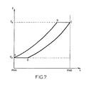
- FIG. 7 is a diagram illustrating the variations of the pressure P inside the cylinder, as a function of the displacement h of the piston, during a complete cycle of opening / closing of the valve;
- Figures 8 and 9 are diagrams similar to that of Figure 7, illustrating cycles of opening / closing the valve, with regulation of the supply pressure.
Sur la figure 1 est représenté un dispositif de rappel 1 d'une soupape 2 d'un moteur à combustion interne dont on a seulement représenté la tubulure 3 d'admission (ou d'échappement) dont la soupape 2 commande l'ouverture et la fermeture.FIG. 1 shows a return device 1 of a
Comme cela est visible sur la figure 1, la soupape 2 comporte une tige 4 qui se termine, à l'une de ses extrémités, par une tête 5 apte à venir en appui contre un siège 6 qui forme l'embouchure de la tubulure d'admission 3.As can be seen in FIG. 1, the
La tige 4 se termine, à son extrémité opposée, par une queue 7 conformée en un suiveur de came qui est maintenu en appui par un ressort pneumatique 8 (décrit ci-dessous) contre une came 9 d'un arbre à cames dont la rotation commande l'ouverture et la fermeture de la soupape 2.The
La soupape 2 est munie d'un piston 10 qui, solidaire de la tige de soupape 4, est monté coulissant dans un cylindre 11.The
Le dispositif 1 comporte également une alimentation 12 en fluide sous pression, raccordée fluidiquement au cylindre 11 par un canal d'alimentation 13 sur lequel est placé un clapet anti-retour 14.The device 1 also comprises a
Le dispositif 1 comporte en outre un clapet de surpression 15 relié fluidiquement, d'une part au cylindre 11 par un canal d'évacuation 16 et, d'autre part, à l'alimentation 12 par un canal de dérivation 17 qui, comme cela est visible sur les figures 1 à 6, se raccorde à l'alimentation 12 en amont du clapet anti-retour 14.The device 1 further comprises a
Le clapet de surpression 15 comporte un cylindre 18 dans lequel coulisse un piston 19 dont est solidaire une soupape 20. Le piston 19 divise le cylindre 18 en deux chambres isolées de manière étanche, à savoir une chambre dite de surpression 21, dans laquelle débouche le canal de dérivation 17, et une chambre de détente 22 dans laquelle débouche le canal d'évacuation 16 et un canal de mise à l'air libre 23 grâce auquel la pression régnant dans la chambre de détente 22 est constamment égale à la pression atmosphérique.The
Le piston 19 est monté mobile entre une position dite de fermeture, illustrée sur la figure 1, dans laquelle la soupape 20 obture le canal d'évacuation 16, et une position dite d'ouverture, illustrée sur la figure 3, dans laquelle la soupape 20 est écartée du canal d'évacuation 16 qu'elle met ainsi en communication avec la chambre de détente 22.The
L'on note SP la superficie de la surface du piston 19 tournée du côté de la chambre de surpression 21, et SS la superficie de la surface de la soupape 20 tournée du côté du côté du canal d'évacuation 16.S P is the area of the surface of the
Comme cela apparaît sur les figures 1 à 6, le clapet de surpression 15 est équipé d'un ressort de rappel 24 qui sollicite en permanence le piston 19 vers sa position de fermeture.As shown in Figures 1 to 6, the
Suivant un mode de réalisation illustré sur les figures 1 à 6, l'alimentation 12 comporte un régulateur de pression relié, par un canal 26, à une source de fluide sous pression (non représentée), ce régulateur étant agencé pour faire varier la pression dans le canal d'alimentation 13 en fonction d'un ou plusieurs paramètres déterminés tels que le régime moteur, lequel est caractérisé par la vitesse de rotation - notée VR - de l'arbre moteur.According to an embodiment illustrated in FIGS. 1 to 6, the
L'on note :
- PA la pression d'alimentation, qui règne dans le
canal d'alimentation 13 en amont du clapet anti-retour 14 et dans le canal de dérivation 17 ; - P1 la pression de tarage du clapet anti-retour 14 ;
- P2 la pression de tarage du clapet de surpression 15, résultant de la force de rappel exercée sur le piston
par le ressort 24 ; - P la pression qui règne dans le cylindre 11, dans le
canal d'alimentation 13 en aval du clapet anti-retour 14 et dans lecanal d'évacuation 16 ; - Pm la valeur minimale de la pression P, cette valeur minimale vérifiant la relation suivante :

- λ le rapport (constant) des superficies SP et SS :

- PM la valeur maximale de la pression P. Cette valeur correspond à la pression qui règne dans la chambre de surpression 21, et vérifie par conséquent la relation suivante :

- et enfin P0 la pression atmosphérique.
- P A the supply pressure, prevailing in the
feed channel 13 upstream of thecheck valve 14 and into thebypass channel 17; - P 1 the calibration pressure of the
non-return valve 14; - P 2 the calibration pressure of the
pressure relief valve 15, resulting from the restoring force exerted on the piston by thespring 24; - P the pressure in the
cylinder 11, in thefeed channel 13 downstream of thenon-return valve 14 and in thedischarge channel 16; - P m the minimum value of the pressure P, this minimum value satisfying the following relation:
- λ the ratio (constant) of areas S P and S S :
- P M the maximum value of the pressure P. This value corresponds to the pressure that prevails in the
booster chamber 21, and therefore verifies the following relation: - and finally P 0 the atmospheric pressure.
Le clapet de surpression 15 est agencé pour limiter la pression P régnant dans le cylindre 11 à la pression maximale PM : en effet, lorsque la pression P atteint ou dépasse cette pression maximale PM, le fluide du canal d'évacuation 16, en provenance du cylindre 11, exerce sur la soupape 20 une pression qui compense la pression PM régnant dans la chambre de surpression 21, ce qui tend à déplacer le piston 19, initialement dans sa position de fermeture, vers sa position d'ouverture, mettant ainsi le canal d'évacuation 16 en communication avec la chambre de détente 22.The
On décrit ci-après le fonctionnement du dispositif 1.The operation of the device 1 is described below.
Sur la figure 1, la soupape est représentée à son point mort haut (PMH voir figure 7) où, plaquée contre le siège 6, elle obture la tubulure d'admission 3.In Figure 1, the valve is shown at its top dead center (TDC see Figure 7) where, pressed against the
Dans cette position, la somme P + P1 des pressions régnant à l'intérieur du cylindre 11 et de tarage du clapet anti-retour 14 est inférieure ou égale à la pression d'alimentation PA, ce qui provoque l'ouverture du clapet anti-retour 14 jusqu'à l'équilibrage des pressions, qui se produit lorsque P = Pm.In this position, the sum P + P 1 of the pressures inside the
Lorsque cet équilibrage se produit, le clapet anti-retour 14 se referme (figure 2), ce qui correspond au point A sur le diagramme de la figure 7.When this balancing occurs, the
La rotation de la came 9 (figure 3) provoque alors le déplacement de la soupape 2 en direction de sa position d'ouverture, ce qui comprime le fluide contenu dans le cylindre 11.The rotation of the cam 9 (FIG. 3) then causes the
Il se produit une augmentation de la pression P jusqu'à ce que la valeur de celle-ci atteigne la pression maximale PM, ce qui correspond au point B du diagramme de la figure 7.There is an increase in the pressure P until the value thereof reaches the maximum pressure P M , which corresponds to point B of the diagram of FIG. 7.
A cet instant, il se produit un équilibrage des pressions dans le clapet de surpression 15 : le piston 19 est repoussé vers sa position d'ouverture, le canal d'évacuation 16 étant ainsi mis en communication avec la chambre de détente 22. La pression P est ainsi maintenue égale à la pression maximale PM.At this moment, there is a balancing of the pressures in the pressure relief valve 15: the
Cette situation, qui correspond à la ligne joignant les points B et C sur le diagramme de la figure 7, perdure tant que le mouvement de la came 9 tend à comprimer le fluide qui se trouve dans le cylindre 11 (figure 4).This situation, which corresponds to the line joining the points B and C in the diagram of FIG. 7, continues as long as the movement of the cam 9 tends to compress the fluid that is in the cylinder 11 (FIG. 4).
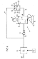
Lorsque la soupape 2 atteint son point mort bas (PMB), le fluide présent dans le cylindre 11 ne tend plus à être compressé, de sorte que la pression PM qui règne dans la chambre de surpression 21 est suffisante pour repousser le piston 19 vers sa position de fermeture, la soupape 20 obturant ainsi à nouveau le canal d'évacuation 16 (figure 5), ce qui correspond au point C sur le diagramme de la figure 7.When the
La rotation de la came 9 permet alors à la soupape 2, sous l'effet du ressort pneumatique 8 constitué par le fluide sous pression présent dans le cylindre 11, qui maintient le suiveur de came 7 en contact permanent avec la came 9, de remonter vers sa position de fermeture, comme cela est représenté sur la figure 6. Il se produit alors une détente du fluide présent dans le cylindre 11, ce qui correspond à la ligne joignant les points C et D sur le diagramme de la figure 7.The rotation of the cam 9 then allows the
Cette détente se poursuit jusqu'à ce que la pression P du fluide présent dans le cylindre 11 atteigne sa valeur minimale Pm (point D sur le diagramme de la figure 7), ce qui provoque l'ouverture du clapet anti-retour 14 (figure 6).This expansion continues until the pressure P of the fluid present in the
Cette situation (correspondant à la ligne joignant les points D et A sur le diagramme de la figure 7) perdure tant que la soupape 2 n'a pas atteint à nouveau son point mort haut, la pression P du fluide présent dans le cylindre 11 étant ainsi maintenue constante et égale à la valeur minimale Pm malgré le mouvement de la soupape 2 qui, suivant la came 9, tend à détendre le fluide.This situation (corresponding to the line joining the points D and A in the diagram of FIG. 7) continues as long as the
Dès lors que la soupape 2 atteint son point mort haut (figure 1), le cycle qui vient d'être décrit recommence.As soon as the
On comprend que la présence des clapets anti-retour 14 et de surpression 15 permet de borner entre deux valeurs extrêmes (correspondant, respectivement, à la pression minimale Pm et à la pression maximale PM, la force de rappel exercée sur la soupape 2 par le ressort pneumatique 8 constitué par le fluide présent dans le cylindre 11.It will be understood that the presence of
Afin d'optimiser le mouvement de la soupape (et notamment d'éviter son affolement), on souhaite faire varier la raideur du ressort pneumatique 8 en fonction d'un ou plusieurs paramètres déterminés.In order to optimize the movement of the valve (and in particular to avoid its panic), it is desired to vary the stiffness of the
En pratique, on souhaite faire varier cette raideur en fonction du régime moteur, et, plus précisément, on souhaite augmenter la raideur du ressort pneumatique 8 lorsque croît la vitesse de rotation VR de l'arbre moteur, ce qui permet d'augmenter la réactivité de la soupape et de repousser sa limite d'affolement.In practice, it is desired to vary this stiffness as a function of the engine speed, and, more specifically, it is desired to increase the stiffness of the
Sur la figure 8, on a représenté un diagramme illustrant la pression P du fluide contenu dans le cylindre 11 en fonction du déplacement h du piston 10, illustrant trois cycles successifs d'ouverture/fermeture de la soupape 2, entre lesquels on a commandé, d'abord une augmentation de la pression d'alimentation PA consécutive à l'augmentation du régime moteur, puis une diminution de la pression d'alimentation PA consécutive à une baisse du régime moteur.FIG. 8 shows a diagram illustrating the pressure P of the fluid contained in the
Au départ (point A), la pression P est égale à la pression minimale Pm1 correspondant à la pression d'alimentation PA initiale. A cette pression d'alimentation PA initiale correspond également une pression maximale PM1, qui règne dans la chambre de surpression 21.Initially (point A), the pressure P is equal to the minimum pressure P m1 corresponding to the initial supply pressure P A. At this initial supply pressure P A also corresponds to a maximum pressure P M1 , which reigns in the
La phase d'ouverture de la soupape 2 est telle que décrite précédemment (entre les points A et B, courbe en traits pleins), le clapet de surpression 15 intervenant (entre les points B et C) lorsque la pression P atteint la pression maximale PM1.The opening phase of the
On commande (arbitrairement) une augmentation du régime moteur dans la phase de fermeture de la soupape 2, correspondant à la détente du fluide (entre les points C et D du diagramme de la figure 8) : le régulateur 25 commande alors l'augmentation de la pression d'alimentation PA.It controls (arbitrarily) an increase in the engine speed in the closing phase of the
Il en résulte une augmentation de la pression minimale qui s'établit à une nouvelle valeur - notée Pm2 -, tandis que la pression maximale s'établit simultanément, par l'intermédiaire du canal de dérivation 17, à une nouvelle valeur - notée PM2 -, ces nouvelles valeurs Pm2 et PM2 étant respectivement supérieures aux valeurs précédentes Pm1 et PM1.This results in an increase of the minimum pressure which is established at a new value - noted P m2 -, while the maximum pressure is established simultaneously, through the
Lorsque la pression P atteint la pression minimale Pm2, le clapet anti-retour 14 entre en action, la pression P restant alors constante et égale à la valeur Pm2 jusqu'à ce que la soupape atteigne à nouveau son point mort haut (point A' sur le diagramme de la figure 8).When the pressure P reaches the minimum pressure P m2 , the
Le ressort pneumatique 8 se trouve ainsi modifié par rapport au cycle précédent, sa raideur étant supérieure.The
La phase d'ouverture de la soupape est telle que décrite précédemment (points B' et C', courbe en pointillés). Au cours de la phase de fermeture de la soupape 2 (entre les points C' et D'), on commande (arbitrairement) une baisse du régime moteur : le régulateur 25 commande alors une diminution de la pression d'alimentation PA, la pression minimale s'établissant alors à une nouvelle valeur Pm3 tandis que la pression maximale, qui règne dans la chambre de surpression 21 s'établit à une nouvelle valeur PM3, ces nouvelles valeurs Pm3 et PM3 étant, respectivement, inférieures aux valeurs initiales Pm1 et PM1.The opening phase of the valve is as described above (points B 'and C', dotted line). During the closing phase of the valve 2 (between the points C 'and D'), a reduction of the engine speed is controlled (arbitrarily): the
Lorsque la pression P atteint, au cours de la détente, la valeur Pm3 (point D'), le clapet de surpression 14 entre en action pour maintenir constante à cette valeur la pression P (entre les points D' et A''), tant que la soupape 2 n'a pas atteint son point mort haut (point A").When the pressure P reaches, during the expansion, the value P m3 (point D '), the
La phase d'ouverture de la soupape 2 se répète alors comme précédemment (entre les points A" et B", puis entre les points B" et C", courbe en trait mixte), le ressort pneumatique 8 présentant toutefois une raideur inférieure à la raideur qu'il présentait durant les deux cycles précédents ;The opening phase of the
Au cours de la détente (entre les points C" et D"), on suppose qu'il se produit à nouveau une augmentation du régime moteur, lequel retrouve sa valeur initiale.During the relaxation (between the points C "and D"), it is assumed that an increase in the engine speed occurs again, which returns to its initial value.
Le régulateur 25 commande alors une augmentation de la pression d'alimentation PA, les pressions minimale et maximale retrouvant alors leurs valeurs initiales respectives Pm1 et PM1.The
Lorsque la pression P atteint la valeur minimale Pm1 (point D"), le clapet 14 entre alors en action pour maintenir constante à cette valeur la pression P (entre les points D" et A).When the pressure P reaches the minimum value P m1 (point D "), the
La figure 9 illustre un cycle d'ouverture/fermeture de la soupape 2, au cours duquel se produisent successivement :
- pendant la phase d'ouverture, une baisse du régime moteur avant que la pression P n'ait atteint la pression maximale initiale PM1 mais après qu'elle a dépassé la nouvelle valeur PM2 résultant de la régulation de la pression d'alimentation PA, et
- au cours de la détente, une augmentation subite du régime moteur avant que la pression P n'ait atteint la valeur minimale Pm2 correspondant à cette régulation, mais après que la pression P soit passée sous la valeur Pm3 issue de la nouvelle régulation de la pression d'alimentation PA.
- during the opening phase, a decrease in the engine speed before the pressure P has reached the initial maximum pressure P M1 but after it has exceeded the new value P M2 resulting from the regulation of the supply pressure P A , and
- during the expansion, a sudden increase in the engine speed before the pressure P has reached the minimum value P m2 corresponding to this regulation, but after the pressure P has passed below the value P m3 resulting from the new regulation of the supply pressure P A.
Au départ (point A), la pression minimale se trouve à une valeur Pm1, la soupape 2 étant à son point mort haut.Initially (point A), the minimum pressure is at a value P m1 , the
La rotation de la came 9 provoque, comme décrit précédemment, la compression du fluide présent dans le cylindre 11. Toutefois, il se produit, à un instant donné (point B1 sur le diagramme de la figure 9) où la pression P n'a pas encore atteint la valeur maximale PM1, une brusque baisse de régime moteur ayant pour conséquence la commande, par le régulateur 25, de la diminution de la pression d'alimentation PA, les pressions minimales et maximales s'établissant alors à des valeurs Pm2 et PM2 inférieures, respectivement, aux valeurs initiales Pm1 et PM1.The rotation of the cam 9 causes, as previously described, the compression of the fluid present in the
La surpression provoque immédiatement l'ouverture du clapet 15, la pression P chutant jusqu'à atteindre la nouvelle valeur de la pression maximale PM2 (point B2).The overpressure immediately causes the
Il est à noter que, sur le diagramme de la figure 9, on n'a pas pris en compte l'inertie du système, de sorte que le segment reliant les points B1 et B2 apparaît à la fois rectiligne et vertical.It should be noted that, in the diagram of FIG. 9, the inertia of the system has not been taken into account, so that the segment connecting the points B 1 and B 2 appears both rectilinear and vertical.
La suite du cycle est (momentanément) telle que décrit précédemment. La pression P est maintenue constante et égale à la valeur PM2 jusqu'au point mort bas (point C) où se produit la fermeture du clapet de surpression 15, le cycle entamant alors sa phase d'ouverture de la soupape 2.The rest of the cycle is (momentarily) as previously described. The pressure P is kept constant and equal to the value P M2 to the bottom dead point (point C) where the closure of the
Au cours de la détente, il se produit, avant que la pression P n'ait atteint la valeur minimale courante Pm2 (point D1), une brusque remontée du régime moteur que le régulateur 25 répercute par une augmentation de la pression d'alimentation, la pression minimale s'établissant alors à une nouvelle valeur Pm3 supérieure dans l'exemple décrit, aux valeurs précédentes Pm1 et Pm2.During the expansion, it occurs, before the pressure P has reached the current minimum value P m2 (point D 1 ), a sudden rise in the engine speed that the
Le clapet anti-retour 14 entre alors en action, la pression P remontant alors brusquement jusqu'à la nouvelle valeur minimale Pm3 (point D2), valeur qu'elle conserve jusqu'au point mort haut (point A').The
De même que précédemment, on a négligé l'inertie du système, de sorte que le segment qui relie sur le diagramme de la figure 9 les points D1 et D2 apparaît à la fois rectiligne et vertical.As before, the inertia of the system has been neglected, so that the segment which connects in the diagram of FIG. 9 the points D 1 and D 2 appears both rectilinear and vertical.
Comme nous venons de le voir, le dispositif de rappel 1 permet de réguler, non seulement la pression minimale Pm requise dans le cylindre 11, mais également la pression maximale PM, en fonction de la pression d'alimentation PA.As we have just seen, the return device 1 makes it possible to regulate, not only the minimum pressure P m required in the
Cette régulation répond à une loi de type affine, ce qui permet de réguler de manière précise la raideur du ressort pneumatique 8 en fonction notamment, comme présenté ci-dessus, du régime moteur.This regulation responds to a law of the affine type, which makes it possible to precisely regulate the stiffness of the
Comme nous l'avons vu, cette régulation s'opère de manière simple et rapide, puisque le clapet de surpression 15 est directement raccordé à l'alimentation 12.As we have seen, this regulation operates simply and quickly, since the
La structure décrite ci-dessus (en particulier la présence du canal de dérivation 17 et du ressort de rappel 24) permet d'établir de manière simple la loi de pression affine PM = λPA + P2 à laquelle obéit la pression maximale PM.The structure described above (in particular the presence of the
Simultanément, la pression minimale Pm obéit également à une loi de type affine, puisqu'elle vérifie la relation Pm = PA - P1, ce qui résulte de la présence sur le canal d'alimentation 13 du clapet anti retour 14.Simultaneously, the minimum pressure P m also obeys an affine type law, since it verifies the relation P m = P A -P 1 , which results from the presence on the
On peut ainsi commander une variation linéaire de la raideur du ressort pneumatique 8 en fonction (comme nous l'avons vu) du régime moteur, de telle sorte que cette raideur soit à la fois suffisamment élevée (ce qui résulte de la régulation de la pression minimale Pm) pour éviter l'affolement des soupapes, mais suffisamment mesurée pour éviter une usure prématurée des pièces en contact, à savoir la queue de soupape 7 et la came 9 correspondante.It is thus possible to control a linear variation of the stiffness of the
Claims (10)
- A return device (1) for a valve (2) of an internal-combustion engine, including:- a piston (10) integral with said valve (2), mounted to slide in a cylinder (11),- a pressurised fluid feed (12) connected to said cylinder by a feed line (13), and- an overpressure valve (15) connected to said cylinder (11) by an evacuation line (16), arranged to limit the pressure (P) in the cylinder (11) to a maximum predetermined pressure (PM),this device being characterised in having means (25, 17, 24) to control the maximum pressure (PM) as a function of the feed pressure according to a law of the affine type.
- A device (1) according to Claim 1, in which the maximum pressure (PM) is a function of the feed pressure according to a law of the type:

where:PM is the maximum pressure,λ is a constant,PA is the feed pressure, andP2 is a constant. - A device (1) according to Claim 2, in which the overpressure valve (15) is equipped with a return spring (24), the constant P2 is the set pressure of said overpressure valve (15) provided by said return spring (24).
- A device (1) according to one of Claims 1 through 3, in which the overpressure valve (15) is connected to the feed (12) by a bypass line (17).
- A device (1) according to one of Claims 1 through 4, which includes a check valve (14) positioned on the feed line (13).
- A device (1) according to Claims 4 and 5, taken together, in which the bypass line (17) is connected to the feed (12) upstream of the check valve (14).
- A device (1) according to one of Claims 1 through 6, in which the feed (12) is controlled by regulating the feed pressure (PA) as a function of one or more determined parameters.
- A device (1) according to Claim 7, in which the feed (12) is controlled to regulate the feed pressure (PA) as a function of the engine speed (VR).
- A device (1) according to Claim 8, in which the feed (12) is controlled to increase the feed pressure (PA) when the engine speed (VR) increases.
- An internal-combustion engine equipped with a return device (1) according to one of Claims 1 through 9.
Applications Claiming Priority (2)
| Application Number | Priority Date | Filing Date | Title |
|---|---|---|---|
| FR0402764 | 2004-03-17 | ||
| FR0402764A FR2867807B1 (en) | 2004-03-17 | 2004-03-17 | DEVICE FOR RECALLING A VALVE AND MOTOR EQUIPPED WITH SUCH A DEVICE |
Publications (2)
| Publication Number | Publication Date |
|---|---|
| EP1577508A1 EP1577508A1 (en) | 2005-09-21 |
| EP1577508B1 true EP1577508B1 (en) | 2007-04-11 |
Family
ID=34834186
Family Applications (1)
| Application Number | Title | Priority Date | Filing Date |
|---|---|---|---|
| EP05290548A Expired - Lifetime EP1577508B1 (en) | 2004-03-17 | 2005-03-11 | Valve return device motor provided with such a device |
Country Status (8)
| Country | Link |
|---|---|
| US (1) | US7249580B2 (en) |
| EP (1) | EP1577508B1 (en) |
| JP (1) | JP2005264942A (en) |
| AU (1) | AU2005201158A1 (en) |
| CA (1) | CA2500689A1 (en) |
| DE (1) | DE602005000844T2 (en) |
| ES (1) | ES2285652T3 (en) |
| FR (1) | FR2867807B1 (en) |
Cited By (1)
| Publication number | Priority date | Publication date | Assignee | Title |
|---|---|---|---|---|
| EP3841287B1 (en) * | 2018-08-23 | 2024-02-14 | Volvo Truck Corporation | Cylinder valve assembly with valve spring venting arrangement |
Families Citing this family (5)
| Publication number | Priority date | Publication date | Assignee | Title |
|---|---|---|---|---|
| DE102007022652A1 (en) * | 2007-05-15 | 2008-11-20 | Daimler Ag | Gas exchange valve actuating device |
| EP2208870B1 (en) | 2009-01-20 | 2013-03-27 | BRP-Powertrain GmbH & Co. KG | Air spring system for an internal combustion engine |
| EP2211031B1 (en) * | 2009-01-22 | 2013-07-10 | BRP-Powertrain GmbH & Co. KG | Air spring with cap |
| EP3406866A1 (en) * | 2017-05-22 | 2018-11-28 | EMPA Eidgenössische Materialprüfungs- und Forschungsanstalt | Hydraulic drive for accelerating and braking components to be dynamically moved |
| AT526848B1 (en) * | 2023-04-28 | 2024-08-15 | Avl List Gmbh | PNEUMATIC VALVE SPRING SYSTEM |
Family Cites Families (13)
| Publication number | Priority date | Publication date | Assignee | Title |
|---|---|---|---|---|
| US2342003A (en) * | 1941-11-12 | 1944-02-15 | Wright Aeronautical Corp | Pressure operated valve gear |
| FR2529616B1 (en) | 1982-06-30 | 1987-03-27 | Renault Sport | PNEUMATIC VALVE RECALL SYSTEM FOR AN INTERNAL COMBUSTION ENGINE |
| DE3808542C2 (en) * | 1987-03-26 | 1994-03-24 | Volkswagen Ag | Valve train for a gas exchange valve of an internal combustion engine |
| DK167499B1 (en) * | 1991-06-27 | 1993-11-08 | Man B & W Diesel Gmbh | SAVING AIR ENGINE ARRANGEMENTS |
| DE69211942T2 (en) | 1991-08-21 | 1996-10-31 | Honda Motor Co Ltd | Lift valve control device for internal combustion engines |
| JPH0559916A (en) * | 1991-08-27 | 1993-03-09 | Honda Motor Co Ltd | Air valve spring system for internal combustion engine |
| JPH0519506U (en) * | 1991-08-27 | 1993-03-12 | 本田技研工業株式会社 | Air valve spring device for internal combustion engine |
| JPH0559917A (en) * | 1991-08-27 | 1993-03-09 | Honda Motor Co Ltd | Air valve spring system for internal combustion engine |
| JP3135634B2 (en) * | 1991-09-13 | 2001-02-19 | 本田技研工業株式会社 | Air spring type valve train for internal combustion engine |
| FR2711729B1 (en) * | 1993-10-29 | 1995-12-01 | Peugeot | Pneumatic valve return system for internal combustion engine. |
| JP2000224405A (en) * | 1999-01-29 | 2000-08-11 | Dainippon Screen Mfg Co Ltd | Image processing method |
| FR2806146B1 (en) * | 2000-03-10 | 2002-10-25 | Sagem | ELECTROMAGNETIC VALVE CONTROL DEVICE WITH PNEUMATIC SPRINGS |
| US6738706B2 (en) * | 2002-06-19 | 2004-05-18 | Ford Global Technologies, Llc | Method for estimating engine parameters |
-
2004
- 2004-03-17 FR FR0402764A patent/FR2867807B1/en not_active Expired - Fee Related
-
2005
- 2005-03-11 EP EP05290548A patent/EP1577508B1/en not_active Expired - Lifetime
- 2005-03-11 ES ES05290548T patent/ES2285652T3/en not_active Expired - Lifetime
- 2005-03-11 DE DE602005000844T patent/DE602005000844T2/en not_active Expired - Fee Related
- 2005-03-15 CA CA002500689A patent/CA2500689A1/en not_active Abandoned
- 2005-03-16 JP JP2005074435A patent/JP2005264942A/en active Pending
- 2005-03-16 US US11/081,188 patent/US7249580B2/en not_active Expired - Fee Related
- 2005-03-17 AU AU2005201158A patent/AU2005201158A1/en not_active Abandoned
Cited By (1)
| Publication number | Priority date | Publication date | Assignee | Title |
|---|---|---|---|---|
| EP3841287B1 (en) * | 2018-08-23 | 2024-02-14 | Volvo Truck Corporation | Cylinder valve assembly with valve spring venting arrangement |
Also Published As
| Publication number | Publication date |
|---|---|
| ES2285652T3 (en) | 2007-11-16 |
| EP1577508A1 (en) | 2005-09-21 |
| AU2005201158A1 (en) | 2005-10-06 |
| JP2005264942A (en) | 2005-09-29 |
| US7249580B2 (en) | 2007-07-31 |
| US20050217619A1 (en) | 2005-10-06 |
| DE602005000844T2 (en) | 2007-12-13 |
| FR2867807B1 (en) | 2006-07-07 |
| FR2867807A1 (en) | 2005-09-23 |
| CA2500689A1 (en) | 2005-09-17 |
| DE602005000844D1 (en) | 2007-05-24 |
Similar Documents
| Publication | Publication Date | Title |
|---|---|---|
| EP1979591B1 (en) | Pressure device for a variable compression ratio engine | |
| EP1341992B1 (en) | Valve actuating device, and method for controlling same | |
| EP2307687B1 (en) | Ball lift device for adjusting the compression ratio of a variable compression ratio engine | |
| FR2556774A1 (en) | DEVICE FOR STOPPING THE VALVE CONTROL FOR A MULTI-CYLINDER ENGINE | |
| FR2517740A1 (en) | DEVICE FOR CONTROLLING THE OPERATION OF THE VALVES OF AN INTERNAL COMBUSTION ENGINE | |
| CH644187A5 (en) | FUEL INJECTION DEVICE, PARTICULARLY FOR DIESEL ENGINES. | |
| FR2862114A1 (en) | Hydraulic clutch control system for motor vehicle, has assistance device placed in assistance cylinder to apply force on assistance piston during declutch phase, where cylinder is placed in pipe coupling master and slave cylinders | |
| EP1502006A1 (en) | Variable flow reducing valve and gradual control valve distribution system for a compressed air injection engine operating on mono or multi energy and other engines or compressors | |
| EP1577508B1 (en) | Valve return device motor provided with such a device | |
| FR2673246A1 (en) | DEVICE FOR INJECTING LIQUID, PARTICULARLY FUEL, IN AT LEAST ONE PRESSURIZED CHAMBER OF A PERIODICALLY OPERATING MACHINE SUCH AS AN INTERNAL COMBUSTION ENGINE AND SUCH AN ENGINE PROVIDED WITH SUCH A DEVICE. | |
| FR2741670A1 (en) | MOTOR-MECHANICAL WORKING CONTROL DEVICE FOR LOAD CHANGE VALVES | |
| EP0040121B1 (en) | Valve rocker disconnector | |
| FR2468732A1 (en) | VARIABLE DISTRIBUTION WITH HYDRAULIC CONTROL FOR INTERNAL COMBUSTION ENGINES | |
| FR2496170A1 (en) | DEVICE FOR CONTROLLING THE FUEL SUPPLY OF AN INTERNAL COMBUSTION ENGINE | |
| EP0677138A1 (en) | Pneumatic valve return system for internal combustion engine | |
| FR2896538A1 (en) | Electromechanical device, has mechanical unit transmitting movement between electric motor and control rod of control jack of control device, where unit has cam shaft which is positioned above cylinder head of jack | |
| FR2464372A1 (en) | METHOD AND DEVICE FOR IMPROVING THE EFFICIENCY OF AN INTERNAL COMBUSTION ENGINE BY SELECTIVE VARIATION AT THE ACTUAL COMPRESSION RATE ACCORDING TO THE MOTOR RPM | |
| FR2482194A1 (en) | DECOMPRESSION DEVICE FOR INTERNAL COMBUSTION ENGINE | |
| EP1132581B1 (en) | Electromagnetic valve with pneumatic spring and toggle drive mechanism | |
| EP0498682A1 (en) | Deactivating valve operating device for an internal combustion engine | |
| EP0180510B1 (en) | Hydraulic piston pump with positively driven inlet valves | |
| FR2677704A1 (en) | Hydraulic device for taking up the play (adjusting the tappets) for internal combustion engine timing | |
| FR2570123A1 (en) | Device for the variable control of a valve with a stem for an internal combustion engine | |
| FR2676501A1 (en) | Device for actuating a valve in order to vary its lift and/or timing | |
| FR3054002A1 (en) | HYDRAULIC VALVE CONTROL SYSTEM FOR INTERNAL COMBUSTION ENGINE WITH MAXIMUM ENERGY RECOVERY |
Legal Events
| Date | Code | Title | Description |
|---|---|---|---|
| PUAI | Public reference made under article 153(3) epc to a published international application that has entered the european phase |
Free format text: ORIGINAL CODE: 0009012 |
|
| AK | Designated contracting states |
Kind code of ref document: A1 Designated state(s): AT BE BG CH CY CZ DE DK EE ES FI FR GB GR HU IE IS IT LI LT LU MC NL PL PT RO SE SI SK TR |
|
| AX | Request for extension of the european patent |
Extension state: AL BA HR LV MK YU |
|
| 17P | Request for examination filed |
Effective date: 20060307 |
|
| AKX | Designation fees paid |
Designated state(s): DE ES GB IT |
|
| GRAP | Despatch of communication of intention to grant a patent |
Free format text: ORIGINAL CODE: EPIDOSNIGR1 |
|
| GRAS | Grant fee paid |
Free format text: ORIGINAL CODE: EPIDOSNIGR3 |
|
| GRAA | (expected) grant |
Free format text: ORIGINAL CODE: 0009210 |
|
| AK | Designated contracting states |
Kind code of ref document: B1 Designated state(s): DE ES GB IT |
|
| REG | Reference to a national code |
Ref country code: GB Ref legal event code: FG4D Free format text: NOT ENGLISH |
|
| REF | Corresponds to: |
Ref document number: 602005000844 Country of ref document: DE Date of ref document: 20070524 Kind code of ref document: P |
|
| GBT | Gb: translation of ep patent filed (gb section 77(6)(a)/1977) |
Effective date: 20070712 |
|
| REG | Reference to a national code |
Ref country code: ES Ref legal event code: FG2A Ref document number: 2285652 Country of ref document: ES Kind code of ref document: T3 |
|
| PLBE | No opposition filed within time limit |
Free format text: ORIGINAL CODE: 0009261 |
|
| STAA | Information on the status of an ep patent application or granted ep patent |
Free format text: STATUS: NO OPPOSITION FILED WITHIN TIME LIMIT |
|
| 26N | No opposition filed |
Effective date: 20080114 |
|
| PGFP | Annual fee paid to national office [announced via postgrant information from national office to epo] |
Ref country code: ES Payment date: 20090323 Year of fee payment: 5 |
|
| PGFP | Annual fee paid to national office [announced via postgrant information from national office to epo] |
Ref country code: GB Payment date: 20090303 Year of fee payment: 5 |
|
| PGFP | Annual fee paid to national office [announced via postgrant information from national office to epo] |
Ref country code: DE Payment date: 20090312 Year of fee payment: 5 Ref country code: IT Payment date: 20090319 Year of fee payment: 5 |
|
| GBPC | Gb: european patent ceased through non-payment of renewal fee |
Effective date: 20100311 |
|
| PG25 | Lapsed in a contracting state [announced via postgrant information from national office to epo] |
Ref country code: DE Free format text: LAPSE BECAUSE OF NON-PAYMENT OF DUE FEES Effective date: 20101001 |
|
| PG25 | Lapsed in a contracting state [announced via postgrant information from national office to epo] |
Ref country code: GB Free format text: LAPSE BECAUSE OF NON-PAYMENT OF DUE FEES Effective date: 20100311 Ref country code: IT Free format text: LAPSE BECAUSE OF NON-PAYMENT OF DUE FEES Effective date: 20100311 |
|
| REG | Reference to a national code |
Ref country code: ES Ref legal event code: FD2A Effective date: 20110415 |
|
| PG25 | Lapsed in a contracting state [announced via postgrant information from national office to epo] |
Ref country code: ES Free format text: LAPSE BECAUSE OF NON-PAYMENT OF DUE FEES Effective date: 20110404 |
|
| PG25 | Lapsed in a contracting state [announced via postgrant information from national office to epo] |
Ref country code: ES Free format text: LAPSE BECAUSE OF NON-PAYMENT OF DUE FEES Effective date: 20100312 |