EP1577508B1 - Ventilrückholvorrichtung und Motor mit solcher Vorrichtung - Google Patents
Ventilrückholvorrichtung und Motor mit solcher Vorrichtung Download PDFInfo
- Publication number
- EP1577508B1 EP1577508B1 EP05290548A EP05290548A EP1577508B1 EP 1577508 B1 EP1577508 B1 EP 1577508B1 EP 05290548 A EP05290548 A EP 05290548A EP 05290548 A EP05290548 A EP 05290548A EP 1577508 B1 EP1577508 B1 EP 1577508B1
- Authority
- EP
- European Patent Office
- Prior art keywords
- pressure
- valve
- feed
- cylinder
- return
- Prior art date
- Legal status (The legal status is an assumption and is not a legal conclusion. Google has not performed a legal analysis and makes no representation as to the accuracy of the status listed.)
- Expired - Lifetime
Links
- 239000012530 fluid Substances 0.000 claims description 19
- 238000002485 combustion reaction Methods 0.000 claims description 9
- PXFBZOLANLWPMH-UHFFFAOYSA-N 16-Epiaffinine Natural products C1C(C2=CC=CC=C2N2)=C2C(=O)CC2C(=CC)CN(C)C1C2CO PXFBZOLANLWPMH-UHFFFAOYSA-N 0.000 claims description 6
- 238000011144 upstream manufacturing Methods 0.000 claims description 4
- 230000001105 regulatory effect Effects 0.000 claims description 3
- 238000010586 diagram Methods 0.000 description 15
- 230000033228 biological regulation Effects 0.000 description 9
- 230000009471 action Effects 0.000 description 4
- 230000009257 reactivity Effects 0.000 description 3
- 240000008042 Zea mays Species 0.000 description 2
- 238000012550 audit Methods 0.000 description 2
- 238000006073 displacement reaction Methods 0.000 description 2
- 230000003416 augmentation Effects 0.000 description 1
- 230000006835 compression Effects 0.000 description 1
- 238000007906 compression Methods 0.000 description 1
- 230000001627 detrimental effect Effects 0.000 description 1
- 230000000694 effects Effects 0.000 description 1
- 230000000977 initiatory effect Effects 0.000 description 1
- 230000002028 premature Effects 0.000 description 1
- 230000009467 reduction Effects 0.000 description 1
- 230000004044 response Effects 0.000 description 1
- 230000000284 resting effect Effects 0.000 description 1
- 230000000630 rising effect Effects 0.000 description 1
- 238000013022 venting Methods 0.000 description 1
Images


Classifications
-
- F—MECHANICAL ENGINEERING; LIGHTING; HEATING; WEAPONS; BLASTING
- F01—MACHINES OR ENGINES IN GENERAL; ENGINE PLANTS IN GENERAL; STEAM ENGINES
- F01L—CYCLICALLY OPERATING VALVES FOR MACHINES OR ENGINES
- F01L1/00—Valve-gear or valve arrangements, e.g. lift-valve gear
- F01L1/46—Component parts, details, or accessories, not provided for in preceding subgroups
- F01L1/462—Valve return spring arrangements
- F01L1/465—Pneumatic arrangements
Definitions
- the invention relates to the control of valves in internal combustion engines.
- It relates to a valve return device and an internal combustion engine equipped with such a device.
- the motors are equipped with return devices which comprise, for each valve, a spring which urges it permanently in the direction of its closure (that is to say in the direction of the cam corresponding).
- the proposed system comprises a piston integral with a valve stem and sliding in a cylinder, the piston, the valve stem and the cylinder forming a sealed chamber which encloses a compressible fluid at a predetermined minimum setting pressure corresponding to the fully closed position of the valve.
- valve control system so proposed is an advance over the system of the document FR-2 529 616, the structure used to provide pressure control is however relatively complex, while its reactivity, insufficient, is detrimental to sudden changes in engine speed.
- the invention aims in particular to overcome the aforementioned drawbacks, by proposing a return device for precise regulation of the return force to which the valve is subjected and which, while having increased reactivity (in other words a reduced response time, especially during sudden changes in engine speed), can further reduce the risk of panic valves.
- the pressure relief valve is provided with a return spring, in which case the constant P 2 is the set pressure of said pressure relief valve provided by said return spring.
- the pressure relief valve is for example connected to the supply by a bypass channel.
- non-return valve placed on the supply channel, the bypass channel being connected to the supply upstream of the non-return valve.
- the power supply can be controlled to regulate the supply pressure according to one or more determined parameters, such as the engine speed.
- the power supply is preferably controlled to increase the supply pressure as the engine speed increases.
- the invention proposes an internal combustion engine equipped with a return device as presented above.
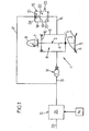
- FIG. 1 shows a return device 1 of a valve 2 of an internal combustion engine of which only the intake (or exhaust) pipe 3 has been shown, the valve 2 of which controls the opening and the closing.
- the valve 2 comprises a rod 4 which ends, at one of its ends, with a head 5 able to bear against a seat 6 which forms the mouth of the tubing of admission 3.
- the rod 4 ends, at its opposite end, with a tail 7 shaped as a cam follower which is held in abutment by a pneumatic spring 8 (described below) against a cam 9 of a camshaft whose rotation controls the opening and closing of the valve 2.
- the valve 2 is provided with a piston 10 which, secured to the valve stem 4, is slidably mounted in a cylinder 11.
- the device 1 also comprises a supply 12 of fluid under pressure, fluidly connected to the cylinder 11 by a supply channel 13 on which is placed a check valve 14.
- the device 1 further comprises a pressure relief valve 15 fluidly connected, on the one hand to the cylinder 11 by a discharge channel 16 and, on the other hand, to the supply 12 by a bypass channel 17 which, as can be seen in FIGS. 1 to 6, is connected to the supply 12 upstream of the non-return valve 14.
- the pressure relief valve 15 comprises a cylinder 18 in which slides a piston 19 which is integral with a valve 20.
- the piston 19 divides the cylinder 18 into two sealed chambers, namely a so-called overpressure chamber 21, into which the bypass channel 17, and an expansion chamber 22 in which the discharge channel 16 opens and a venting channel 23 through which the pressure in the expansion chamber 22 is constantly equal to atmospheric pressure.
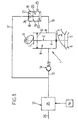
- the piston 19 is movably mounted between a so-called closing position, illustrated in FIG. 1, in which the valve 20 closes off the evacuation channel 16, and a so-called opening position, illustrated in FIG. 3, in which the valve 20 is separated from the evacuation channel 16 that it thus communicates with the expansion chamber 22.
- S P is the area of the surface of the piston 19 turned on the side of the pressure chamber 21, and S S the area of the surface of the valve 20 turned towards the side of the discharge channel 16.
- the pressure relief valve 15 is equipped with a return spring 24 which constantly urges the piston 19 to its closed position.
- the supply 12 comprises a pressure regulator connected via a channel 26 to a source of pressurized fluid (not shown), this regulator being arranged to vary the pressure in the feed channel 13 as a function of one or more determined parameters such as the engine speed, which is characterized by the rotational speed - denoted V R - of the motor shaft.
- the pressure relief valve 15 is designed to limit the pressure P prevailing in the cylinder 11 to the maximum pressure P M : indeed, when the pressure P reaches or exceeds this maximum pressure P M , the fluid of the discharge channel 16, in from the cylinder 11, exerts on the valve 20 a pressure which compensates the pressure P M prevailing in the pressure chamber 21, which tends to move the piston 19, initially in its closed position, to its open position, putting thus the evacuation channel 16 in communication with the chamber of relaxation 22.
- valve is shown at its top dead center (TDC see Figure 7) where, pressed against the seat 6, it closes the intake manifold 3.
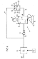
- check valves 14 and of overpressure 15 makes it possible to limit between two extreme values (corresponding, respectively, to the minimum pressure P m and to the maximum pressure P M , the restoring force exerted on the valve 2 by the air spring 8 constituted by the fluid present in the cylinder 11.
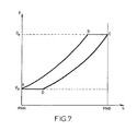
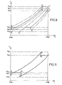
- FIG. 8 shows a diagram illustrating the pressure P of the fluid contained in the cylinder 11 as a function of the displacement h of the piston 10, illustrating three successive cycles of opening / closing of the valve 2, between which it has been controlled, first an increase in the supply pressure P A consecutive to the increase in the engine speed, then a decrease in the supply pressure P A following a decrease in engine speed.
- the pressure P is equal to the minimum pressure P m1 corresponding to the initial supply pressure P A.
- P A also corresponds to a maximum pressure P M1 , which reigns in the overpressure chamber 21.
- the opening phase of the valve 2 is as previously described (between the points A and B, curve in solid lines), the pressure relief valve 15 intervening (between points B and C) when the pressure P reaches the maximum pressure. P M1 .
- the regulator 25 controls (arbitrarily) an increase in the engine speed in the closing phase of the valve 2, corresponding to the expansion of the fluid (between the points C and D of the diagram of FIG. 8): the regulator 25 then controls the increase of the supply pressure P A.
- the air spring 8 is thus modified with respect to the previous cycle, its stiffness being greater.
- the opening phase of the valve is as described above (points B 'and C', dotted line).
- a reduction of the engine speed is controlled (arbitrarily): the regulator 25 then controls a decrease in the supply pressure P A , the the minimum pressure is then established at a new value P m3 while the maximum pressure prevailing in the booster chamber 21 is set at a new value P M3 , these new values P m3 and P M3 being, respectively, less than initial values P m1 and P M1 .
- the opening phase of the valve 2 is then repeated as before (between the points A “and B”, then between the points B “and C”, curve in phantom), the air spring 8 however having a stiffness less than the stiffness that it presented during the two previous cycles;
- the regulator 25 then controls an increase in the supply pressure P A , the minimum and maximum pressures then returning to their respective initial values P m1 and P M1 .
- the rotation of the cam 9 causes, as previously described, the compression of the fluid present in the cylinder 11. However, it occurs at a given moment (point B 1 in the diagram of FIG. 9) where the pressure P n ' has not yet reached the maximum value P M1 , a sudden drop in engine speed resulting in the control by the regulator 25, of the decrease of the supply pressure P A , the minimum and maximum pressures then being set to values P m2 and P M2 lower, respectively, to the initial values P m1 and P M1 .
- the overpressure immediately causes the valve 15 to open, the pressure P falling until reaching the new value of the maximum pressure P M2 (point B 2 ).
- the rest of the cycle is (momentarily) as previously described.
- the pressure P is kept constant and equal to the value P M2 to the bottom dead point (point C) where the closure of the pressure relief valve 15 occurs, the cycle then initiating its opening phase of the valve 2.
- the non-return valve 14 then enters into action, the pressure P then rising abruptly to the new minimum value P m3 (point D 2 ), which value it conserves up to the top dead point (point A ').
- the return device 1 makes it possible to regulate, not only the minimum pressure P m required in the cylinder 11, but also the pressure maximum P M, depending on the supply pressure P A.
- This regulation responds to a law of the affine type, which makes it possible to precisely regulate the stiffness of the air spring 8 in particular as a function of the engine speed, as shown above.
Landscapes
- Engineering & Computer Science (AREA)
- Mechanical Engineering (AREA)
- General Engineering & Computer Science (AREA)
- Valve Device For Special Equipments (AREA)
Claims (10)
- Rückholvorrichtung (1) eines Ventils (2) eines Motors mit Innenverbrennung, welche umfasst:- einen fest mit dem Ventil (2) verbundenen, in einem Zylinder (11) gleitbeweglich montierten Kolben (10),- eine Druckfluidversorgung (12), die mit dem Zylinder über einen Versorgungskanal (13) verbunden ist, und- ein Überdruckventil (15), das an den Zylinder (11) über einen Entleerungskanal (16) angeschlossen ist und eingerichtet ist, den in dem Zylinder (11) herrschenden Druck (P) auf einen vorgegebenen Maximaldruck (PM) zu beschränken,dadurch gekennzeichnet, dass sie Mittel (25, 17, 24) zum Regeln des Maximaldrucks (PM) in Abhängigkeit vom Versorgungsdruck nach einer Regel vom linearen Typ umfasst.
- Vorrichtung nach Anspruch 1, bei der der Maximaldruck (PM) Funktion des Versorgungsdrucks nach einer Regel vom Typ:

ist, wobeiPM der Maximaldruck ist,λ eine Konstante ist,PA der Versorgungsdruck ist undP2 eine Konstante ist. - Vorrichtung nach Anspruch 2, bei der das Überdruckventil (15) mit einer Rückholfeder (24) versehen ist und die Konstante P2 der von der Rückholfeder (24) gelieferte Einstelldruck des Überdruckventils (15) ist.
- Vorrichtung (1) nach einem der Ansprüche 1 bis 3, bei der das Überdruckventil (15) an die Versorgung (12) über einen Abzweigkanal (17) angeschlossen ist.
- Vorrichtung (1) nach einem der Ansprüche 1 bis 4, die ein an dem Versorgungskanal (13) angeordnetes Rückschlagventil (14) aufweist.
- Vorrichtung (1) nach Anspruch 4 und nach Anspruch 5, bei der der Abzweigkanal (17) mit der Versorgung (12) stromaufwärts vom Rückschlagventil (14) verbunden ist.
- Vorrichtung (1) nach einem der Ansprüche 1 bis 6, bei der die Versorgung (12) zum Regeln des Versorgungsdrucks (PA) in Abhängigkeit von einem oder mehreren festgelegten Parametern gesteuert ist.
- Vorrichtung (1) nach Anspruch 7, bei der die Versorgung (12) gesteuert ist, um den Versorgungsdruck (PA) in Abhängigkeit vom Motorregime (VR) zu regeln.
- Vorrichtung nach Anspruch 8, bei der die Versorgung (12) gesteuert ist, um den Versorgungsdruck (PA) zu erhöhen, wenn das Motorregime (VR) zunimmt.
- Motor mit Innenverbrennung, ausgestattet mit einer Rückholvorrichtung (1) nach einem der Ansprüche 1 bis 9.
Applications Claiming Priority (2)
| Application Number | Priority Date | Filing Date | Title |
|---|---|---|---|
| FR0402764 | 2004-03-17 | ||
| FR0402764A FR2867807B1 (fr) | 2004-03-17 | 2004-03-17 | Dispositif de rappel d'une soupape et moteur equipe d'un tel dispositif |
Publications (2)
| Publication Number | Publication Date |
|---|---|
| EP1577508A1 EP1577508A1 (de) | 2005-09-21 |
| EP1577508B1 true EP1577508B1 (de) | 2007-04-11 |
Family
ID=34834186
Family Applications (1)
| Application Number | Title | Priority Date | Filing Date |
|---|---|---|---|
| EP05290548A Expired - Lifetime EP1577508B1 (de) | 2004-03-17 | 2005-03-11 | Ventilrückholvorrichtung und Motor mit solcher Vorrichtung |
Country Status (8)
| Country | Link |
|---|---|
| US (1) | US7249580B2 (de) |
| EP (1) | EP1577508B1 (de) |
| JP (1) | JP2005264942A (de) |
| AU (1) | AU2005201158A1 (de) |
| CA (1) | CA2500689A1 (de) |
| DE (1) | DE602005000844T2 (de) |
| ES (1) | ES2285652T3 (de) |
| FR (1) | FR2867807B1 (de) |
Cited By (1)
| Publication number | Priority date | Publication date | Assignee | Title |
|---|---|---|---|---|
| EP3841287B1 (de) * | 2018-08-23 | 2024-02-14 | Volvo Truck Corporation | Zylinderventilanordnung mit ventilfederentlüftungsvorrichtung |
Families Citing this family (5)
| Publication number | Priority date | Publication date | Assignee | Title |
|---|---|---|---|---|
| DE102007022652A1 (de) * | 2007-05-15 | 2008-11-20 | Daimler Ag | Gaswechselventilbetätigungsvorrichtung |
| EP2208870B1 (de) | 2009-01-20 | 2013-03-27 | BRP-Powertrain GmbH & Co. KG | Luftfedersystem für Verbrennungsmotoren |
| EP2211031B1 (de) * | 2009-01-22 | 2013-07-10 | BRP-Powertrain GmbH & Co. KG | Luftfeder mit Kappe |
| EP3406866A1 (de) * | 2017-05-22 | 2018-11-28 | EMPA Eidgenössische Materialprüfungs- und Forschungsanstalt | Hydraulischer antrieb zum beschleunigen und abbremsen dynamisch zu bewegender bauteile |
| AT526848B1 (de) * | 2023-04-28 | 2024-08-15 | Avl List Gmbh | Pneumatisches ventilfedersystem |
Family Cites Families (13)
| Publication number | Priority date | Publication date | Assignee | Title |
|---|---|---|---|---|
| US2342003A (en) * | 1941-11-12 | 1944-02-15 | Wright Aeronautical Corp | Pressure operated valve gear |
| FR2529616B1 (fr) | 1982-06-30 | 1987-03-27 | Renault Sport | Systeme de rappel pneumatique de soupape pour moteur a combustion interne |
| DE3808542C2 (de) * | 1987-03-26 | 1994-03-24 | Volkswagen Ag | Ventiltrieb für ein Gaswechselventil einer Brennkraftmaschine |
| DK167499B1 (da) * | 1991-06-27 | 1993-11-08 | Man B & W Diesel Gmbh | Spaerreluftarrangement ved en forbraendingsmotor |
| DE69211942T2 (de) | 1991-08-21 | 1996-10-31 | Honda Motor Co Ltd | Hubventilsteuerungsvorrichtung für Brennkraftmaschine |
| JPH0559916A (ja) * | 1991-08-27 | 1993-03-09 | Honda Motor Co Ltd | 内燃機関のエアバルブスプリングシステム |
| JPH0519506U (ja) * | 1991-08-27 | 1993-03-12 | 本田技研工業株式会社 | 内燃機関のエアバルブスプリング装置 |
| JPH0559917A (ja) * | 1991-08-27 | 1993-03-09 | Honda Motor Co Ltd | 内燃機関のエアバルブスプリングシステム |
| JP3135634B2 (ja) * | 1991-09-13 | 2001-02-19 | 本田技研工業株式会社 | 内燃エンジンの空気ばね式動弁装置 |
| FR2711729B1 (fr) * | 1993-10-29 | 1995-12-01 | Peugeot | Système de rappel pneumatique de soupape pour moteur à combustion interne. |
| JP2000224405A (ja) * | 1999-01-29 | 2000-08-11 | Dainippon Screen Mfg Co Ltd | 画像処理方法 |
| FR2806146B1 (fr) * | 2000-03-10 | 2002-10-25 | Sagem | Dispositif de commande electromagnetique de soupapes, a ressorts pneumatiques |
| US6738706B2 (en) * | 2002-06-19 | 2004-05-18 | Ford Global Technologies, Llc | Method for estimating engine parameters |
-
2004
- 2004-03-17 FR FR0402764A patent/FR2867807B1/fr not_active Expired - Fee Related
-
2005
- 2005-03-11 EP EP05290548A patent/EP1577508B1/de not_active Expired - Lifetime
- 2005-03-11 ES ES05290548T patent/ES2285652T3/es not_active Expired - Lifetime
- 2005-03-11 DE DE602005000844T patent/DE602005000844T2/de not_active Expired - Fee Related
- 2005-03-15 CA CA002500689A patent/CA2500689A1/fr not_active Abandoned
- 2005-03-16 JP JP2005074435A patent/JP2005264942A/ja active Pending
- 2005-03-16 US US11/081,188 patent/US7249580B2/en not_active Expired - Fee Related
- 2005-03-17 AU AU2005201158A patent/AU2005201158A1/en not_active Abandoned
Cited By (1)
| Publication number | Priority date | Publication date | Assignee | Title |
|---|---|---|---|---|
| EP3841287B1 (de) * | 2018-08-23 | 2024-02-14 | Volvo Truck Corporation | Zylinderventilanordnung mit ventilfederentlüftungsvorrichtung |
Also Published As
| Publication number | Publication date |
|---|---|
| ES2285652T3 (es) | 2007-11-16 |
| EP1577508A1 (de) | 2005-09-21 |
| AU2005201158A1 (en) | 2005-10-06 |
| JP2005264942A (ja) | 2005-09-29 |
| US7249580B2 (en) | 2007-07-31 |
| US20050217619A1 (en) | 2005-10-06 |
| DE602005000844T2 (de) | 2007-12-13 |
| FR2867807B1 (fr) | 2006-07-07 |
| FR2867807A1 (fr) | 2005-09-23 |
| CA2500689A1 (fr) | 2005-09-17 |
| DE602005000844D1 (de) | 2007-05-24 |
Similar Documents
| Publication | Publication Date | Title |
|---|---|---|
| EP1979591B1 (de) | Druckvorrichtung für einen motor mit variabler verdichtung | |
| EP1341992B1 (de) | Vorrichtung zum betätigen der ventile und steuerungsverfahren dafür | |
| EP2307687B1 (de) | Kugelhubvorrichtung zur einstellung des verdichtungsverhältnisses für einen motor mit veränderlichem verdichtungsverhältnis | |
| FR2556774A1 (fr) | Dispositif d'arret de la commande des soupapes pour un moteur a plusieurs cylindres | |
| FR2517740A1 (fr) | Dispositif de commande d'actionnement des soupapes d'un moteur a combustion interne | |
| CH644187A5 (fr) | Dispositif d'injection de combustible, notamment pour des moteurs diesel. | |
| FR2862114A1 (fr) | Systeme de commande hydraulique d'un embrayage comportant des moyens d'assistance interposes entre l'emetteur et le recepteur du systeme. | |
| EP1502006A1 (de) | Expansionsvorrichtung mit variabler abnahme und progressive ventilsteuerung für druckluftmotoren | |
| EP1577508B1 (de) | Ventilrückholvorrichtung und Motor mit solcher Vorrichtung | |
| FR2673246A1 (fr) | Dispositif d'injection de liquide, notamment de combustible, dans au moins une chambre pressurisee d'une machine a fonctionnement periodique tel que moteur a combustion interne et moteur de ce type equipe de ce dispositif. | |
| FR2741670A1 (fr) | Dispositif de commande travaillant de facon mecano-hydraulique pour des soupapes de changement de charge | |
| EP0040121B1 (de) | Vorrichtung zum Abschalten eines Ventilfallhebers | |
| FR2468732A1 (fr) | Distribution variable a commande hydraulique pour moteurs a combustion interne | |
| FR2496170A1 (fr) | Dispositif de commande de l'alimentation en carburant d'un moteur a combustion interne | |
| EP0677138A1 (de) | Pneumatische ventilrückstellvorrichtung für eine brennkraftmaschine | |
| FR2896538A1 (fr) | Dispositif electromecanique de commande d'un moteur a rapport volumetrique variable | |
| FR2464372A1 (fr) | Procede et dispositif pour ameliorer le rendement d'un moteur a combustion interne par variation selective au taux de compression effectif selon le regime du moteur | |
| FR2482194A1 (fr) | Dispositif de decompression pour moteur a combustion interne | |
| EP1132581B1 (de) | Elektromagnetventil mit Pneumatikfeder und Kniehebelmechanismus | |
| EP0498682A1 (de) | Ventilsteuervorrichtung zum Ausschalten für eine Brennkraftmaschine | |
| EP0180510B1 (de) | Hydraulische Kolbenpumpe mit zwangsläufig angetriebenen Einlassventilen | |
| FR2677704A1 (fr) | Dispositif hydraulique de rattrapage de jeu pour distribution de moteur a combustion interne. | |
| FR2570123A1 (fr) | Dispositif de commande variable d'une soupape a tige pour moteur a combustion interne | |
| FR2676501A1 (fr) | Dispositif d'actionnement d'une soupape pour en faire varier la levee et/ou le calage. | |
| FR3054002A1 (fr) | Systeme de commande hydraulique de soupapes pour moteur a combustion interne avec recuperation d'energie maximale |
Legal Events
| Date | Code | Title | Description |
|---|---|---|---|
| PUAI | Public reference made under article 153(3) epc to a published international application that has entered the european phase |
Free format text: ORIGINAL CODE: 0009012 |
|
| AK | Designated contracting states |
Kind code of ref document: A1 Designated state(s): AT BE BG CH CY CZ DE DK EE ES FI FR GB GR HU IE IS IT LI LT LU MC NL PL PT RO SE SI SK TR |
|
| AX | Request for extension of the european patent |
Extension state: AL BA HR LV MK YU |
|
| 17P | Request for examination filed |
Effective date: 20060307 |
|
| AKX | Designation fees paid |
Designated state(s): DE ES GB IT |
|
| GRAP | Despatch of communication of intention to grant a patent |
Free format text: ORIGINAL CODE: EPIDOSNIGR1 |
|
| GRAS | Grant fee paid |
Free format text: ORIGINAL CODE: EPIDOSNIGR3 |
|
| GRAA | (expected) grant |
Free format text: ORIGINAL CODE: 0009210 |
|
| AK | Designated contracting states |
Kind code of ref document: B1 Designated state(s): DE ES GB IT |
|
| REG | Reference to a national code |
Ref country code: GB Ref legal event code: FG4D Free format text: NOT ENGLISH |
|
| REF | Corresponds to: |
Ref document number: 602005000844 Country of ref document: DE Date of ref document: 20070524 Kind code of ref document: P |
|
| GBT | Gb: translation of ep patent filed (gb section 77(6)(a)/1977) |
Effective date: 20070712 |
|
| REG | Reference to a national code |
Ref country code: ES Ref legal event code: FG2A Ref document number: 2285652 Country of ref document: ES Kind code of ref document: T3 |
|
| PLBE | No opposition filed within time limit |
Free format text: ORIGINAL CODE: 0009261 |
|
| STAA | Information on the status of an ep patent application or granted ep patent |
Free format text: STATUS: NO OPPOSITION FILED WITHIN TIME LIMIT |
|
| 26N | No opposition filed |
Effective date: 20080114 |
|
| PGFP | Annual fee paid to national office [announced via postgrant information from national office to epo] |
Ref country code: ES Payment date: 20090323 Year of fee payment: 5 |
|
| PGFP | Annual fee paid to national office [announced via postgrant information from national office to epo] |
Ref country code: GB Payment date: 20090303 Year of fee payment: 5 |
|
| PGFP | Annual fee paid to national office [announced via postgrant information from national office to epo] |
Ref country code: DE Payment date: 20090312 Year of fee payment: 5 Ref country code: IT Payment date: 20090319 Year of fee payment: 5 |
|
| GBPC | Gb: european patent ceased through non-payment of renewal fee |
Effective date: 20100311 |
|
| PG25 | Lapsed in a contracting state [announced via postgrant information from national office to epo] |
Ref country code: DE Free format text: LAPSE BECAUSE OF NON-PAYMENT OF DUE FEES Effective date: 20101001 |
|
| PG25 | Lapsed in a contracting state [announced via postgrant information from national office to epo] |
Ref country code: GB Free format text: LAPSE BECAUSE OF NON-PAYMENT OF DUE FEES Effective date: 20100311 Ref country code: IT Free format text: LAPSE BECAUSE OF NON-PAYMENT OF DUE FEES Effective date: 20100311 |
|
| REG | Reference to a national code |
Ref country code: ES Ref legal event code: FD2A Effective date: 20110415 |
|
| PG25 | Lapsed in a contracting state [announced via postgrant information from national office to epo] |
Ref country code: ES Free format text: LAPSE BECAUSE OF NON-PAYMENT OF DUE FEES Effective date: 20110404 |
|
| PG25 | Lapsed in a contracting state [announced via postgrant information from national office to epo] |
Ref country code: ES Free format text: LAPSE BECAUSE OF NON-PAYMENT OF DUE FEES Effective date: 20100312 |