EP1577481B1 - Elément stratifié avec couche intermédiaire en saillie et pliée sur un bord dudit élément - Google Patents
Elément stratifié avec couche intermédiaire en saillie et pliée sur un bord dudit élément Download PDFInfo
- Publication number
- EP1577481B1 EP1577481B1 EP05075628A EP05075628A EP1577481B1 EP 1577481 B1 EP1577481 B1 EP 1577481B1 EP 05075628 A EP05075628 A EP 05075628A EP 05075628 A EP05075628 A EP 05075628A EP 1577481 B1 EP1577481 B1 EP 1577481B1
- Authority
- EP
- European Patent Office
- Prior art keywords
- flat element
- element according
- intermediate layer
- jaw
- extended
- Prior art date
- Legal status (The legal status is an assumption and is not a legal conclusion. Google has not performed a legal analysis and makes no representation as to the accuracy of the status listed.)
- Expired - Lifetime
Links
- 239000011521 glass Substances 0.000 claims description 47
- 230000013011 mating Effects 0.000 claims description 4
- 239000002861 polymer material Substances 0.000 claims description 4
- 230000006978 adaptation Effects 0.000 claims description 2
- 229910052751 metal Inorganic materials 0.000 description 3
- 230000000694 effects Effects 0.000 description 2
- 239000002184 metal Substances 0.000 description 2
- 239000007779 soft material Substances 0.000 description 2
- 229910000831 Steel Inorganic materials 0.000 description 1
- 230000015572 biosynthetic process Effects 0.000 description 1
- 239000003795 chemical substances by application Substances 0.000 description 1
- 230000006866 deterioration Effects 0.000 description 1
- 238000010438 heat treatment Methods 0.000 description 1
- 239000013521 mastic Substances 0.000 description 1
- 239000000463 material Substances 0.000 description 1
- 238000000034 method Methods 0.000 description 1
- 229920001296 polysiloxane Polymers 0.000 description 1
- 239000011150 reinforced concrete Substances 0.000 description 1
- 230000000717 retained effect Effects 0.000 description 1
- 238000007789 sealing Methods 0.000 description 1
- 239000010959 steel Substances 0.000 description 1
- 230000000007 visual effect Effects 0.000 description 1
- XLYOFNOQVPJJNP-UHFFFAOYSA-N water Substances O XLYOFNOQVPJJNP-UHFFFAOYSA-N 0.000 description 1
- 239000002023 wood Substances 0.000 description 1
Images
Classifications
-
- E—FIXED CONSTRUCTIONS
- E06—DOORS, WINDOWS, SHUTTERS, OR ROLLER BLINDS IN GENERAL; LADDERS
- E06B—FIXED OR MOVABLE CLOSURES FOR OPENINGS IN BUILDINGS, VEHICLES, FENCES OR LIKE ENCLOSURES IN GENERAL, e.g. DOORS, WINDOWS, BLINDS, GATES
- E06B3/00—Window sashes, door leaves, or like elements for closing wall or like openings; Layout of fixed or moving closures, e.g. windows in wall or like openings; Features of rigidly-mounted outer frames relating to the mounting of wing frames
- E06B3/54—Fixing of glass panes or like plates
- E06B3/5427—Fixing of glass panes or like plates the panes mounted flush with the surrounding frame or with the surrounding panes
-
- B—PERFORMING OPERATIONS; TRANSPORTING
- B32—LAYERED PRODUCTS
- B32B—LAYERED PRODUCTS, i.e. PRODUCTS BUILT-UP OF STRATA OF FLAT OR NON-FLAT, e.g. CELLULAR OR HONEYCOMB, FORM
- B32B17/00—Layered products essentially comprising sheet glass, or glass, slag, or like fibres
- B32B17/06—Layered products essentially comprising sheet glass, or glass, slag, or like fibres comprising glass as the main or only constituent of a layer, next to another layer of a specific material
- B32B17/10—Layered products essentially comprising sheet glass, or glass, slag, or like fibres comprising glass as the main or only constituent of a layer, next to another layer of a specific material of synthetic resin
- B32B17/10005—Layered products essentially comprising sheet glass, or glass, slag, or like fibres comprising glass as the main or only constituent of a layer, next to another layer of a specific material of synthetic resin laminated safety glass or glazing
- B32B17/10009—Layered products essentially comprising sheet glass, or glass, slag, or like fibres comprising glass as the main or only constituent of a layer, next to another layer of a specific material of synthetic resin laminated safety glass or glazing characterized by the number, the constitution or treatment of glass sheets
- B32B17/10036—Layered products essentially comprising sheet glass, or glass, slag, or like fibres comprising glass as the main or only constituent of a layer, next to another layer of a specific material of synthetic resin laminated safety glass or glazing characterized by the number, the constitution or treatment of glass sheets comprising two outer glass sheets
-
- B—PERFORMING OPERATIONS; TRANSPORTING
- B32—LAYERED PRODUCTS
- B32B—LAYERED PRODUCTS, i.e. PRODUCTS BUILT-UP OF STRATA OF FLAT OR NON-FLAT, e.g. CELLULAR OR HONEYCOMB, FORM
- B32B17/00—Layered products essentially comprising sheet glass, or glass, slag, or like fibres
- B32B17/06—Layered products essentially comprising sheet glass, or glass, slag, or like fibres comprising glass as the main or only constituent of a layer, next to another layer of a specific material
- B32B17/10—Layered products essentially comprising sheet glass, or glass, slag, or like fibres comprising glass as the main or only constituent of a layer, next to another layer of a specific material of synthetic resin
- B32B17/10005—Layered products essentially comprising sheet glass, or glass, slag, or like fibres comprising glass as the main or only constituent of a layer, next to another layer of a specific material of synthetic resin laminated safety glass or glazing
- B32B17/10165—Functional features of the laminated safety glass or glazing
- B32B17/10293—Edge features, e.g. inserts or holes
- B32B17/10302—Edge sealing
Definitions
- the present invention relates to a stratified flat element in particular for closing surfaces of buildings and the like.
- stratified glass panels which are applied to the fixed structures of the building by means of pin-like components such as through-studs and threaded bosses which, although being very reliable, by passing through the glass give rise, however, to thermal continuity and reduce the sealing effect against water and air leaks.
- the documents WO 0064670 and EP 0,974,451 also disclose stratified glass panels which are formed by two transparent sheets which are glued to an internal layer of polymer material which is extended beyond the edge of the two glass panels so as to allow gripping by corresponding devices to be constrained to the fixed parts of the building.
- the technical problem which is posed, therefore, is that of providing stratified glass elements able to be constrained to fixed structures of buildings and the like without parts which remain visible on the external surface of the said glazed element.
- said glass elements should be able to be obtained using industrial, methods, handled safely and easily for transportation and assembly and have a high residual strength in the event of breakage of the glass element once fitted.
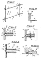
- a stratified glass element according to the present invention is composed essentially of a first transparent sheet of glass 10, conventionally defined as external, and a second sheet of glass 20, conventionally defined as internal, which are joined together by means of the positioning, in between, of an intermediate layer 30 of polymer material, for example of the ion plastic type, having optimum mechanical properties, in particular with regard to the instantaneous modulus of elasticity and the breakage strength.
- Said intermediate layer 30 is extended beyond the perimetral edge of the external sheet 10 and folded at a suitable angle inwards along a section 31 of suitable length.
- the angle of curvature, relative to the surface of the glass element, of said folded section 31 of the intermediate layer 30 is between 20° and 130° with a minimum radius of curvature of 1.5 mm.
- said angle of curvature will be preferably between 80° and 105° and the radius of curvature between 4 and 20 mm.
- the rear sheet 20 of the stratified glass element has a dimension smaller than the corresponding dimension of the external sheet 10.
- said rear sheet 20 may have dimensions the same as those of the front sheet 10 and may be provided with interruptions able to allow passing-through of the intermediate layer 30.
- Figure 3 shows a section of the façade in which two glass elements according to the present invention are arranged adjacent, with the joint between them sealed by means of mastic 60 of the compatible silicone-based type or equivalent material;
- Fig. 3 shows moreover the means 40 for gripping the section 31 of the intermediate layer 30 projecting inwards and, in the example, formed by two jaws 41,42 which grip said projecting section 31 by screw means 43 or the like.
- the polymer material of the intermediate layer facilitates joining to the gripping means 40 following a heating and pressurisation treatment which activates the relative adhesion between the former and latter, increasing the strength of the joint.
- the first jaw 41 extends towards the glass element along a section greater than that of the second jaw 42 and has a convex section 41a corresponding to the curvature 32 of the extended section 31, with which it combines in order to confer rigidity to the assembly.
- Figure 4 shows, moreover, an example of embodiment of the system for securing the glazed elements according to Figure 3 to a flange 2 integral with a fixed upright 1 of the building, said securing action being obtained by means of screw/female thread means 3/3a.
- Figure 5 shows a variation of embodiment of the means 140 for gripping the projecting section 31 of the intermediate layer 30; said gripping means 140 also consist in this case of jaws 141;142 where the second jaw 142 extends towards the glass element so as to form a cavity inside which a seal 50 of soft material is housed so as to avoid direct contact between glass and metal.
- Said second jaw 142 also has, along the section corresponding to the curvature 32, a concave seat 142a for adaptation to the said curvature 32 of the projecting section 31 of the intermediate layer 30.
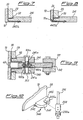
- Figures 6 to 9 show further examples of embodiment of the glass element according to the present invention and the associated gripping devices.
- Figure 6 shows gripping devices 240 which in this case consist of a first jaw 241 which has a first seat 241a for housing the second internal sheet of glass 20 and, on the opposite side, a second seat 241b suitable for engagement with the second jaw 242a so as to allow clamping, by screw-type means or the like, of the intermediate layer 30 of the stratified glass element.
- the dimensions of the first seat 241a are such as to allow the positioning of a stop 50 between glass and jaw.
- Figure 6 shows the external glass sheet 10 and internal glass sheet 20 which have the same length, and the second jaw 242a is correspondingly extended towards the outside of the first jaw with a rounded form.
- the external sheet 10 is longer than the internal sheet 20 and the second jaw 242b is correspondingly cut with a length substantially the same as that of the first jaw 241.
- soft material 50 is arranged between the glass sheet and the metal jaw.
- Figure 9 shows a further variation of embodiment of the means for securing the glazed elements to a flange 102 integral with a fixed upright 101; said securing action is obtained by means of an insert 102a of the said flange 102, which insert has a through-hole with a female thread 102b coaxial with corresponding through-holes 241a in the respective jaws 241; said female thread 102b is suitable for mating with a corresponding thread on a first bolt 103a, the head of which rests on the first jaw 241 and the shank of which has internally a female thread suitable for mating with the threaded shank of a second bolt 103, which is situated opposite to the first bolt and the head of which rests on the respective first jaw 241 of the second glass element.
- the glass element according to the present invention results in an improved versatility from an applicational point of view, allowing the formation of surfaces with any form and able to be associated with the most varying types of support structure, imparting moreover to the glass a high residual strength following possible breakage of the said glass.
- the means for constraining to the fixed structure may be of the pin type arranged in the vicinity of the corners of the glass element or continuous and extending along at least two opposite edges of the stratified glass element; likewise the fixing means may be joined to structures both of the rigid type, such as frames made of steel, reinforced concrete, wood or glass, and of the deformable type, such as tensile structures, and/or cables, as for example shown in Figure 10 where the fixed mounting element is precisely a cable 201 having, mounted thereon, a cable-tensioning device 203,203a able to be arranged on opposite sides of the devices 340 for gripping the stratified glass; said gripping devices 340 also comprise a first jaw 341 and a second jaw 342; the first jaw 341 conveniently has a seat 345 able to allow the entry of the cable 201 and retaining means 345a able to prevent the gripping devices 340 from escaping in the transverse direction.
- the stratified flat sheet may be of the blind and/or semi-transparent type for forming panels for closing openings and/or particular aesthetic effects.
Landscapes
- Engineering & Computer Science (AREA)
- Civil Engineering (AREA)
- Structural Engineering (AREA)
- Securing Of Glass Panes Or The Like (AREA)
- Electroluminescent Light Sources (AREA)
- Joining Of Glass To Other Materials (AREA)
- Piezo-Electric Or Mechanical Vibrators, Or Delay Or Filter Circuits (AREA)
- Surface Acoustic Wave Elements And Circuit Networks Thereof (AREA)
- Laminated Bodies (AREA)
- Shaping Of Tube Ends By Bending Or Straightening (AREA)
- Toys (AREA)
Claims (32)
- Élément plat stratifié comprenant une feuille externe (10) et une feuille interne (20) reliées l'une à l'autre par l'intermédiaire d'une couche intermédiaire (30), ladite couche intermédiaire (30) faisant saillie au-delà d'au moins un des bords périmétriques de l'élément plat et étant repliée vers l'intérieur sur une section (31) de longueur appropriée, caractérisé en ce qu'il comprend des dispositifs (40; 140; 240; 340) destinés à saisir la section replié (31) de la couche intermédiaire (30) et en ce que lesdits dispositifs de saisie se trouvent à l'intérieur par rapport à la surface de verre externe de ladite feuille externe (10).
- Élément plat selon la revendication 1, caractérisé en ce que ladite couche intermédiaire se compose d'un matériau polymère.
- Élément plat selon la revendication 1, caractérisé en ce que ladite couche intermédiaire (30) fait saillie au-delà d'au moins deux bords périmétriques de l'élément plat.
- Élément plat selon la revendication 3, caractérisé en ce que lesdits deux bords périmétriques sont opposés l'un à l'autre.
- Élément plat selon la revendication 3, caractérisé en ce que lesdits deux bords périmétriques sont adjacents l'un à l'autre.
- Élément plat selon la revendication 1, caractérisé en ce que la feuille interne (20) présente une dimension inférieure à celle de la feuille externe (10) au moins à l'endroit où la couche intermédiaire (30) fait saillie et est repliée.
- Élément plat selon la revendication 1, caractérisé en ce que la feuille interne (20) comporte des interruptions pouvant permettre le passage et le repliage de la couche intermédiaire (30).
- Élément plat selon la revendication 1, caractérisé en ce que ladite section en saillie et repliée (31) de la couche intermédiaire (30) est repliée vers l'intérieur, à un angle compris entre 20 et 130.
- Élément plat selon la revendication 8, caractérisé en ce que ledit angle de courbure est de préférence compris entre 80 et 105.
- Élément plat selon la revendication 1, caractérisé en ce que le rayon de courbure minimal de la section en saillie et repliée (31) mesure 1,5 mm.
- Élément plat selon la revendication 10, caractérisé en ce que le rayon de courbure est de préférence compris entre 4 et 20 mm.
- Élément plat selon la revendication 1, caractérisé en ce que lesdits dispositifs de saisie (40; 140; 240; 340) se composent d'une paire de mâchoires (41, 42; 141, 142, 142; 241, 242a, 242b; 241, 442b;241, 341, 342) dont au moins une s'étend aussi loin que l'élément plat.
- Élément plat selon la revendication 12, caractérisé en ce que ladite mâchoire (41; 141) s'étendant aussi loin que l'élément plat présente une section convexe (41 a) ayant une courbure correspondant à celle (32) de la section en saillie (31) de la couche intermédiaire (30).
- Élément plat selon la revendication 12, caractérisé en ce que l'une (42) des deux mâchoires (41, 42) de la paire présente des dimensions inférieures à celles de la première mâchoire (41).
- Élément plat selon la revendication 12, caractérisé en ce que ladite mâchoire (41, 141) s'étendant aussi loin que l'élément plat comporte un premier siège (241 a) destiné à recevoir la deuxième feuille interne de verre (20) et, du côté opposé, un deuxième siège (241 b) approprié pour coopérer avec la deuxième mâchoire (242a) afin de pincer la couche intermédiaire (30) du verre stratifié.
- Élément plat selon la revendication 15, caractérisé en ce que la deuxième mâchoire (242a) s'étend avec une forme arrondie au-delà du bord de la première mâchoire.
- Élément plat selon la revendication 15, caractérisé en ce que la deuxième mâchoire (242b) présente une longueur essentiellement identique à celle de la première mâchoire (241).
- Élément plat selon la revendication 12, caractérisé en ce que la deuxième mâchoire (142) de la paire s'étend vers l'élément plat et comporte un siège concave (142a) destiné à s'adapter à ladite courbure (32) de la section en saillie (31) de la couche intermédiaire (30).
- Élément plat selon la revendication 12, caractérisé en ce que la deuxième mâchoire (442b) de la paire a la forme d'un L.
- Élément plat selon la revendication 19, caractérisé en ce que le bras long du L s'étend de telle sorte que le bras court soit disposé à l'intérieur d'un siège approprié (10a) de la feuille (10).
- Élément plat selon la revendication 19, caractérisé en ce que le bras long du L s'étend de telle sorte que le bras court soit disposé au-delà de la feuille (10).
- Élément plat selon la revendication 12, caractérisé en ce que la deuxième mâchoire (142) s'étend vers l'élément plat de façon à former un espace à l'intérieur duquel est logé un joint (50).
- Élément plat selon la revendication 1, caractérisé en ce que lesdits dispositifs de saisie comportent des trous traversants appropriés pour coopérer avec des moyens correspondants (3, 3a; 103, 103a) permettant un ancrage à des parties de support fixes correspondantes.
- Élément plat selon la revendication 23, caractérisé en ce que lesdits trous traversants sont formés sur la première mâchoire de la paire.
- Élément plat selon la revendication 23, caractérisé en ce que lesdits moyens d'ancrage se composent d'une vis (3) et d'un écrou (3a).
- Élément plat selon la revendication 23, caractérisé en ce que lesdits moyens d'ancrage se composent d'une première vis (103a) sur la tige de laquelle sont formés des filetages mâle et femelle appropriés pour coopérer avec la tige filetée d'une deuxième vis (103), située en face de la première vis.
- Élément plat selon la revendication 26, caractérisé en ce que ledit filetage mâle est approprié pour coopérer avec le filetage femelle (102b) d'une pièce d'insertion (102a) solidaire des moyens fixes (102) destinés à supporter l'élément plat.
- Élément plat selon la revendication 24, caractérisé en ce que ledit trou traversant (345) est ouvert dans le sens longitudinal vers la structure de support et est associé à des moyens correspondants (345a) destinés à fermer l'ouverture.
- Élément plat selon la revendication 1, caractérisé en ce que le joint situé entre la section en saillie et repliée (31) de la couche intermédiaire (30) et lesdits dispositifs de saisie (40) est réalisé par adhérence de la première sur les derniers.
- Élément plat selon la revendication 1, caractérisé en ce que lesdites feuilles (10, 20) sont transparentes.
- Élément plat selon la revendication 1, caractérisé en ce qu'au moins une desdites feuilles (10, 20) est opaque.
- Utilisation de l'élément plat selon la revendication 1 en tant que revêtement pour des surfaces de bâtiments.
Applications Claiming Priority (2)
| Application Number | Priority Date | Filing Date | Title |
|---|---|---|---|
| ITMI20040534 | 2004-03-19 | ||
| IT000534A ITMI20040534A1 (it) | 2004-03-19 | 2004-03-19 | Elemento piano stratificato con strato intermedio prolungato e piegato oltre almeno un bordo perimetrale dell'elemento stesso |
Publications (2)
| Publication Number | Publication Date |
|---|---|
| EP1577481A1 EP1577481A1 (fr) | 2005-09-21 |
| EP1577481B1 true EP1577481B1 (fr) | 2011-01-19 |
Family
ID=34835601
Family Applications (1)
| Application Number | Title | Priority Date | Filing Date |
|---|---|---|---|
| EP05075628A Expired - Lifetime EP1577481B1 (fr) | 2004-03-19 | 2005-03-16 | Elément stratifié avec couche intermédiaire en saillie et pliée sur un bord dudit élément |
Country Status (4)
| Country | Link |
|---|---|
| EP (1) | EP1577481B1 (fr) |
| AT (1) | ATE496195T1 (fr) |
| DE (1) | DE602005025953D1 (fr) |
| IT (1) | ITMI20040534A1 (fr) |
Family Cites Families (4)
| Publication number | Priority date | Publication date | Assignee | Title |
|---|---|---|---|---|
| US5778629A (en) * | 1995-09-28 | 1998-07-14 | Howes; Stephen E. | Impact resistant window |
| US5960606A (en) * | 1997-02-28 | 1999-10-05 | Dlubak; Francis Charles | Penetration resistant window |
| FR2781415B1 (fr) * | 1998-07-24 | 2000-09-01 | Saint Gobain Vitrage | Vitrage feuillete de securite |
| US6737151B1 (en) * | 1999-04-22 | 2004-05-18 | E. I. Du Pont De Nemours And Company | Glass laminates having improved structural integrity against severe impacts |
-
2004
- 2004-03-19 IT IT000534A patent/ITMI20040534A1/it unknown
-
2005
- 2005-03-16 AT AT05075628T patent/ATE496195T1/de not_active IP Right Cessation
- 2005-03-16 DE DE602005025953T patent/DE602005025953D1/de not_active Expired - Lifetime
- 2005-03-16 EP EP05075628A patent/EP1577481B1/fr not_active Expired - Lifetime
Also Published As
| Publication number | Publication date |
|---|---|
| ITMI20040534A1 (it) | 2004-06-19 |
| DE602005025953D1 (de) | 2011-03-03 |
| ATE496195T1 (de) | 2011-02-15 |
| EP1577481A1 (fr) | 2005-09-21 |
Similar Documents
| Publication | Publication Date | Title |
|---|---|---|
| RU2012129954A (ru) | Рамный узел для листового материала | |
| JPH05141152A (ja) | ガラス板固定用取り付け型材構造 | |
| US20150093539A1 (en) | Glass laminate comprising at least one shaped part made of metal | |
| US20160230416A1 (en) | Handle | |
| ES2211070T3 (es) | Elemento constructivo de vidrio para formar una seccion o elemento de pared, de tejado o de cubierta autosoportante. | |
| KR100974922B1 (ko) | 단열 패널 고정구 및 이를 이용한 단열 패널 고정 방법 | |
| EP1577481B1 (fr) | Elément stratifié avec couche intermédiaire en saillie et pliée sur un bord dudit élément | |
| CN104234216B (zh) | 幕墙伸缩缝结构及应用其的幕墙 | |
| ES2690419T3 (es) | Procedimiento y elemento de fijación para instalar un parasol en una parte acristalada | |
| AU2003267369A1 (en) | Supporting framework for a facade | |
| JPH10231571A (ja) | 板ガラスの支持構造 | |
| JP2006241695A (ja) | ガラス板の支持構造 | |
| EP2694307B1 (fr) | Dispositif de calage pour la pose d'un vitrage sur une baie de carrosserie d'un vehicule | |
| JP2010095934A (ja) | ガラス支持構造体 | |
| JP2004124648A (ja) | ガラス板の支持構造 | |
| HU223632B1 (hu) | Elõfeszített, keret nélküli üvegtábla | |
| CZ301126B6 (cs) | Bezrámová tvrzená sklenená tabule | |
| KR101033609B1 (ko) | 취성 물질로 제조된 패널을 고정시키기 위한 시스템 | |
| JP4710731B2 (ja) | 役物外装材 | |
| KR200413016Y1 (ko) | 동질의 유리로 구성된 리브 글라스 및 패치 타입의유리구조물 | |
| JP2006016776A (ja) | ガラス板の支持構造 | |
| KR101719457B1 (ko) | 신속 설치 및 미려한 마감이 가능한 창호 리모델링용 마감 부재 | |
| JP3646760B2 (ja) | 複層ガラス用アタッチメント構造 | |
| US20090065157A1 (en) | Connection device and a method of forming a panel assembly | |
| BR112022018351B1 (pt) | Perfil de quadro de um quadro externo e/ou quadro de folha e processo para sua produção |
Legal Events
| Date | Code | Title | Description |
|---|---|---|---|
| PUAI | Public reference made under article 153(3) epc to a published international application that has entered the european phase |
Free format text: ORIGINAL CODE: 0009012 |
|
| AK | Designated contracting states |
Kind code of ref document: A1 Designated state(s): AT BE BG CH CY CZ DE DK EE ES FI FR GB GR HU IE IS IT LI LT LU MC NL PL PT RO SE SI SK TR |
|
| AX | Request for extension of the european patent |
Extension state: AL BA HR LV MK YU |
|
| 17P | Request for examination filed |
Effective date: 20060228 |
|
| AKX | Designation fees paid |
Designated state(s): AT BE BG CH CY CZ DE DK EE ES FI FR GB GR HU IE IS IT LI LT LU MC NL PL PT RO SE SI SK TR |
|
| AXX | Extension fees paid |
Extension state: YU Payment date: 20060228 Extension state: AL Payment date: 20060228 Extension state: BA Payment date: 20060228 Extension state: MK Payment date: 20060228 |
|
| 17Q | First examination report despatched |
Effective date: 20080404 |
|
| GRAP | Despatch of communication of intention to grant a patent |
Free format text: ORIGINAL CODE: EPIDOSNIGR1 |
|
| GRAS | Grant fee paid |
Free format text: ORIGINAL CODE: EPIDOSNIGR3 |
|
| GRAA | (expected) grant |
Free format text: ORIGINAL CODE: 0009210 |
|
| AK | Designated contracting states |
Kind code of ref document: B1 Designated state(s): AT BE BG CH CY CZ DE DK EE ES FI FR GB GR HU IE IS IT LI LT LU MC NL PL PT RO SE SI SK TR |
|
| AX | Request for extension of the european patent |
Extension state: AL BA MK YU |
|
| REG | Reference to a national code |
Ref country code: GB Ref legal event code: FG4D |
|
| RAP2 | Party data changed (patent owner data changed or rights of a patent transferred) |
Owner name: COOPSETTE SOC. COOP. |
|
| REG | Reference to a national code |
Ref country code: CH Ref legal event code: EP |
|
| REG | Reference to a national code |
Ref country code: IE Ref legal event code: FG4D |
|
| REF | Corresponds to: |
Ref document number: 602005025953 Country of ref document: DE Date of ref document: 20110303 Kind code of ref document: P |
|
| REG | Reference to a national code |
Ref country code: DE Ref legal event code: R096 Ref document number: 602005025953 Country of ref document: DE Effective date: 20110303 |
|
| PGFP | Annual fee paid to national office [announced via postgrant information from national office to epo] |
Ref country code: MC Payment date: 20110331 Year of fee payment: 7 |
|
| REG | Reference to a national code |
Ref country code: NL Ref legal event code: VDEP Effective date: 20110119 |
|
| LTIE | Lt: invalidation of european patent or patent extension |
Effective date: 20110119 |
|
| PG25 | Lapsed in a contracting state [announced via postgrant information from national office to epo] |
Ref country code: GR Free format text: LAPSE BECAUSE OF FAILURE TO SUBMIT A TRANSLATION OF THE DESCRIPTION OR TO PAY THE FEE WITHIN THE PRESCRIBED TIME-LIMIT Effective date: 20110420 Ref country code: LT Free format text: LAPSE BECAUSE OF FAILURE TO SUBMIT A TRANSLATION OF THE DESCRIPTION OR TO PAY THE FEE WITHIN THE PRESCRIBED TIME-LIMIT Effective date: 20110119 Ref country code: PT Free format text: LAPSE BECAUSE OF FAILURE TO SUBMIT A TRANSLATION OF THE DESCRIPTION OR TO PAY THE FEE WITHIN THE PRESCRIBED TIME-LIMIT Effective date: 20110519 Ref country code: SE Free format text: LAPSE BECAUSE OF FAILURE TO SUBMIT A TRANSLATION OF THE DESCRIPTION OR TO PAY THE FEE WITHIN THE PRESCRIBED TIME-LIMIT Effective date: 20110119 Ref country code: IS Free format text: LAPSE BECAUSE OF FAILURE TO SUBMIT A TRANSLATION OF THE DESCRIPTION OR TO PAY THE FEE WITHIN THE PRESCRIBED TIME-LIMIT Effective date: 20110519 Ref country code: ES Free format text: LAPSE BECAUSE OF FAILURE TO SUBMIT A TRANSLATION OF THE DESCRIPTION OR TO PAY THE FEE WITHIN THE PRESCRIBED TIME-LIMIT Effective date: 20110430 |
|
| PGFP | Annual fee paid to national office [announced via postgrant information from national office to epo] |
Ref country code: LU Payment date: 20110504 Year of fee payment: 7 Ref country code: FR Payment date: 20110414 Year of fee payment: 7 |
|
| PG25 | Lapsed in a contracting state [announced via postgrant information from national office to epo] |
Ref country code: PL Free format text: LAPSE BECAUSE OF FAILURE TO SUBMIT A TRANSLATION OF THE DESCRIPTION OR TO PAY THE FEE WITHIN THE PRESCRIBED TIME-LIMIT Effective date: 20110119 Ref country code: FI Free format text: LAPSE BECAUSE OF FAILURE TO SUBMIT A TRANSLATION OF THE DESCRIPTION OR TO PAY THE FEE WITHIN THE PRESCRIBED TIME-LIMIT Effective date: 20110119 Ref country code: SI Free format text: LAPSE BECAUSE OF FAILURE TO SUBMIT A TRANSLATION OF THE DESCRIPTION OR TO PAY THE FEE WITHIN THE PRESCRIBED TIME-LIMIT Effective date: 20110119 Ref country code: BG Free format text: LAPSE BECAUSE OF FAILURE TO SUBMIT A TRANSLATION OF THE DESCRIPTION OR TO PAY THE FEE WITHIN THE PRESCRIBED TIME-LIMIT Effective date: 20110419 Ref country code: NL Free format text: LAPSE BECAUSE OF FAILURE TO SUBMIT A TRANSLATION OF THE DESCRIPTION OR TO PAY THE FEE WITHIN THE PRESCRIBED TIME-LIMIT Effective date: 20110119 Ref country code: AT Free format text: LAPSE BECAUSE OF FAILURE TO SUBMIT A TRANSLATION OF THE DESCRIPTION OR TO PAY THE FEE WITHIN THE PRESCRIBED TIME-LIMIT Effective date: 20110119 Ref country code: CY Free format text: LAPSE BECAUSE OF FAILURE TO SUBMIT A TRANSLATION OF THE DESCRIPTION OR TO PAY THE FEE WITHIN THE PRESCRIBED TIME-LIMIT Effective date: 20110119 |
|
| PGFP | Annual fee paid to national office [announced via postgrant information from national office to epo] |
Ref country code: BE Payment date: 20110415 Year of fee payment: 7 Ref country code: GB Payment date: 20110428 Year of fee payment: 7 |
|
| PGFP | Annual fee paid to national office [announced via postgrant information from national office to epo] |
Ref country code: IT Payment date: 20110428 Year of fee payment: 7 |
|
| PG25 | Lapsed in a contracting state [announced via postgrant information from national office to epo] |
Ref country code: EE Free format text: LAPSE BECAUSE OF FAILURE TO SUBMIT A TRANSLATION OF THE DESCRIPTION OR TO PAY THE FEE WITHIN THE PRESCRIBED TIME-LIMIT Effective date: 20110119 Ref country code: DK Free format text: LAPSE BECAUSE OF FAILURE TO SUBMIT A TRANSLATION OF THE DESCRIPTION OR TO PAY THE FEE WITHIN THE PRESCRIBED TIME-LIMIT Effective date: 20110119 |
|
| REG | Reference to a national code |
Ref country code: CH Ref legal event code: PL |
|
| PLBE | No opposition filed within time limit |
Free format text: ORIGINAL CODE: 0009261 |
|
| STAA | Information on the status of an ep patent application or granted ep patent |
Free format text: STATUS: NO OPPOSITION FILED WITHIN TIME LIMIT |
|
| PG25 | Lapsed in a contracting state [announced via postgrant information from national office to epo] |
Ref country code: SK Free format text: LAPSE BECAUSE OF FAILURE TO SUBMIT A TRANSLATION OF THE DESCRIPTION OR TO PAY THE FEE WITHIN THE PRESCRIBED TIME-LIMIT Effective date: 20110119 Ref country code: RO Free format text: LAPSE BECAUSE OF FAILURE TO SUBMIT A TRANSLATION OF THE DESCRIPTION OR TO PAY THE FEE WITHIN THE PRESCRIBED TIME-LIMIT Effective date: 20110119 Ref country code: CZ Free format text: LAPSE BECAUSE OF FAILURE TO SUBMIT A TRANSLATION OF THE DESCRIPTION OR TO PAY THE FEE WITHIN THE PRESCRIBED TIME-LIMIT Effective date: 20110119 |
|
| 26N | No opposition filed |
Effective date: 20111020 |
|
| REG | Reference to a national code |
Ref country code: IE Ref legal event code: MM4A |
|
| PG25 | Lapsed in a contracting state [announced via postgrant information from national office to epo] |
Ref country code: IE Free format text: LAPSE BECAUSE OF NON-PAYMENT OF DUE FEES Effective date: 20110316 Ref country code: DE Free format text: LAPSE BECAUSE OF NON-PAYMENT OF DUE FEES Effective date: 20111001 Ref country code: CH Free format text: LAPSE BECAUSE OF NON-PAYMENT OF DUE FEES Effective date: 20110331 Ref country code: LI Free format text: LAPSE BECAUSE OF NON-PAYMENT OF DUE FEES Effective date: 20110331 |
|
| REG | Reference to a national code |
Ref country code: DE Ref legal event code: R119 Ref document number: 602005025953 Country of ref document: DE Effective date: 20111001 |
|
| REG | Reference to a national code |
Ref country code: AT Ref legal event code: MK05 Ref document number: 496195 Country of ref document: AT Kind code of ref document: T Effective date: 20110119 |
|
| BERE | Be: lapsed |
Owner name: COOPSETTE SOC. COOP. Effective date: 20120331 |
|
| PG25 | Lapsed in a contracting state [announced via postgrant information from national office to epo] |
Ref country code: MC Free format text: LAPSE BECAUSE OF NON-PAYMENT OF DUE FEES Effective date: 20120331 |
|
| GBPC | Gb: european patent ceased through non-payment of renewal fee |
Effective date: 20120316 |
|
| REG | Reference to a national code |
Ref country code: FR Ref legal event code: ST Effective date: 20121130 |
|
| PG25 | Lapsed in a contracting state [announced via postgrant information from national office to epo] |
Ref country code: BE Free format text: LAPSE BECAUSE OF NON-PAYMENT OF DUE FEES Effective date: 20120331 Ref country code: GB Free format text: LAPSE BECAUSE OF NON-PAYMENT OF DUE FEES Effective date: 20120316 Ref country code: FR Free format text: LAPSE BECAUSE OF NON-PAYMENT OF DUE FEES Effective date: 20120402 |
|
| PG25 | Lapsed in a contracting state [announced via postgrant information from national office to epo] |
Ref country code: IT Free format text: LAPSE BECAUSE OF NON-PAYMENT OF DUE FEES Effective date: 20120316 |
|
| PG25 | Lapsed in a contracting state [announced via postgrant information from national office to epo] |
Ref country code: TR Free format text: LAPSE BECAUSE OF FAILURE TO SUBMIT A TRANSLATION OF THE DESCRIPTION OR TO PAY THE FEE WITHIN THE PRESCRIBED TIME-LIMIT Effective date: 20110119 |
|
| PG25 | Lapsed in a contracting state [announced via postgrant information from national office to epo] |
Ref country code: HU Free format text: LAPSE BECAUSE OF FAILURE TO SUBMIT A TRANSLATION OF THE DESCRIPTION OR TO PAY THE FEE WITHIN THE PRESCRIBED TIME-LIMIT Effective date: 20110119 |
|
| PG25 | Lapsed in a contracting state [announced via postgrant information from national office to epo] |
Ref country code: LU Free format text: LAPSE BECAUSE OF NON-PAYMENT OF DUE FEES Effective date: 20120316 |