EP1577481B1 - Stratified flat element with intermediate layer extended and folded beyond at least one perimetral edge of the said flat element - Google Patents
Stratified flat element with intermediate layer extended and folded beyond at least one perimetral edge of the said flat element Download PDFInfo
- Publication number
- EP1577481B1 EP1577481B1 EP05075628A EP05075628A EP1577481B1 EP 1577481 B1 EP1577481 B1 EP 1577481B1 EP 05075628 A EP05075628 A EP 05075628A EP 05075628 A EP05075628 A EP 05075628A EP 1577481 B1 EP1577481 B1 EP 1577481B1
- Authority
- EP
- European Patent Office
- Prior art keywords
- flat element
- element according
- intermediate layer
- jaw
- extended
- Prior art date
- Legal status (The legal status is an assumption and is not a legal conclusion. Google has not performed a legal analysis and makes no representation as to the accuracy of the status listed.)
- Active
Links
- 239000011521 glass Substances 0.000 claims description 47
- 230000013011 mating Effects 0.000 claims description 4
- 239000002861 polymer material Substances 0.000 claims description 4
- 230000006978 adaptation Effects 0.000 claims description 2
- 229910052751 metal Inorganic materials 0.000 description 3
- 230000000694 effects Effects 0.000 description 2
- 239000002184 metal Substances 0.000 description 2
- 239000007779 soft material Substances 0.000 description 2
- 229910000831 Steel Inorganic materials 0.000 description 1
- 230000015572 biosynthetic process Effects 0.000 description 1
- 239000003795 chemical substances by application Substances 0.000 description 1
- 230000006866 deterioration Effects 0.000 description 1
- 238000010438 heat treatment Methods 0.000 description 1
- 239000013521 mastic Substances 0.000 description 1
- 239000000463 material Substances 0.000 description 1
- 238000000034 method Methods 0.000 description 1
- 229920001296 polysiloxane Polymers 0.000 description 1
- 239000011150 reinforced concrete Substances 0.000 description 1
- 230000000717 retained effect Effects 0.000 description 1
- 238000007789 sealing Methods 0.000 description 1
- 239000010959 steel Substances 0.000 description 1
- 230000000007 visual effect Effects 0.000 description 1
- XLYOFNOQVPJJNP-UHFFFAOYSA-N water Substances O XLYOFNOQVPJJNP-UHFFFAOYSA-N 0.000 description 1
- 239000002023 wood Substances 0.000 description 1
Images
Classifications
-
- E—FIXED CONSTRUCTIONS
- E06—DOORS, WINDOWS, SHUTTERS, OR ROLLER BLINDS IN GENERAL; LADDERS
- E06B—FIXED OR MOVABLE CLOSURES FOR OPENINGS IN BUILDINGS, VEHICLES, FENCES OR LIKE ENCLOSURES IN GENERAL, e.g. DOORS, WINDOWS, BLINDS, GATES
- E06B3/00—Window sashes, door leaves, or like elements for closing wall or like openings; Layout of fixed or moving closures, e.g. windows in wall or like openings; Features of rigidly-mounted outer frames relating to the mounting of wing frames
- E06B3/54—Fixing of glass panes or like plates
- E06B3/5427—Fixing of glass panes or like plates the panes mounted flush with the surrounding frame or with the surrounding panes
-
- B—PERFORMING OPERATIONS; TRANSPORTING
- B32—LAYERED PRODUCTS
- B32B—LAYERED PRODUCTS, i.e. PRODUCTS BUILT-UP OF STRATA OF FLAT OR NON-FLAT, e.g. CELLULAR OR HONEYCOMB, FORM
- B32B17/00—Layered products essentially comprising sheet glass, or glass, slag, or like fibres
- B32B17/06—Layered products essentially comprising sheet glass, or glass, slag, or like fibres comprising glass as the main or only constituent of a layer, next to another layer of a specific material
- B32B17/10—Layered products essentially comprising sheet glass, or glass, slag, or like fibres comprising glass as the main or only constituent of a layer, next to another layer of a specific material of synthetic resin
- B32B17/10005—Layered products essentially comprising sheet glass, or glass, slag, or like fibres comprising glass as the main or only constituent of a layer, next to another layer of a specific material of synthetic resin laminated safety glass or glazing
- B32B17/10009—Layered products essentially comprising sheet glass, or glass, slag, or like fibres comprising glass as the main or only constituent of a layer, next to another layer of a specific material of synthetic resin laminated safety glass or glazing characterized by the number, the constitution or treatment of glass sheets
- B32B17/10036—Layered products essentially comprising sheet glass, or glass, slag, or like fibres comprising glass as the main or only constituent of a layer, next to another layer of a specific material of synthetic resin laminated safety glass or glazing characterized by the number, the constitution or treatment of glass sheets comprising two outer glass sheets
-
- B—PERFORMING OPERATIONS; TRANSPORTING
- B32—LAYERED PRODUCTS
- B32B—LAYERED PRODUCTS, i.e. PRODUCTS BUILT-UP OF STRATA OF FLAT OR NON-FLAT, e.g. CELLULAR OR HONEYCOMB, FORM
- B32B17/00—Layered products essentially comprising sheet glass, or glass, slag, or like fibres
- B32B17/06—Layered products essentially comprising sheet glass, or glass, slag, or like fibres comprising glass as the main or only constituent of a layer, next to another layer of a specific material
- B32B17/10—Layered products essentially comprising sheet glass, or glass, slag, or like fibres comprising glass as the main or only constituent of a layer, next to another layer of a specific material of synthetic resin
- B32B17/10005—Layered products essentially comprising sheet glass, or glass, slag, or like fibres comprising glass as the main or only constituent of a layer, next to another layer of a specific material of synthetic resin laminated safety glass or glazing
- B32B17/10165—Functional features of the laminated safety glass or glazing
- B32B17/10293—Edge features, e.g. inserts or holes
- B32B17/10302—Edge sealing
Definitions
- the present invention relates to a stratified flat element in particular for closing surfaces of buildings and the like.
- stratified glass panels which are applied to the fixed structures of the building by means of pin-like components such as through-studs and threaded bosses which, although being very reliable, by passing through the glass give rise, however, to thermal continuity and reduce the sealing effect against water and air leaks.
- the documents WO 0064670 and EP 0,974,451 also disclose stratified glass panels which are formed by two transparent sheets which are glued to an internal layer of polymer material which is extended beyond the edge of the two glass panels so as to allow gripping by corresponding devices to be constrained to the fixed parts of the building.
- the technical problem which is posed, therefore, is that of providing stratified glass elements able to be constrained to fixed structures of buildings and the like without parts which remain visible on the external surface of the said glazed element.
- said glass elements should be able to be obtained using industrial, methods, handled safely and easily for transportation and assembly and have a high residual strength in the event of breakage of the glass element once fitted.
- a stratified glass element according to the present invention is composed essentially of a first transparent sheet of glass 10, conventionally defined as external, and a second sheet of glass 20, conventionally defined as internal, which are joined together by means of the positioning, in between, of an intermediate layer 30 of polymer material, for example of the ion plastic type, having optimum mechanical properties, in particular with regard to the instantaneous modulus of elasticity and the breakage strength.
- Said intermediate layer 30 is extended beyond the perimetral edge of the external sheet 10 and folded at a suitable angle inwards along a section 31 of suitable length.
- the angle of curvature, relative to the surface of the glass element, of said folded section 31 of the intermediate layer 30 is between 20° and 130° with a minimum radius of curvature of 1.5 mm.
- said angle of curvature will be preferably between 80° and 105° and the radius of curvature between 4 and 20 mm.
- the rear sheet 20 of the stratified glass element has a dimension smaller than the corresponding dimension of the external sheet 10.
- said rear sheet 20 may have dimensions the same as those of the front sheet 10 and may be provided with interruptions able to allow passing-through of the intermediate layer 30.
- Figure 3 shows a section of the façade in which two glass elements according to the present invention are arranged adjacent, with the joint between them sealed by means of mastic 60 of the compatible silicone-based type or equivalent material;
- Fig. 3 shows moreover the means 40 for gripping the section 31 of the intermediate layer 30 projecting inwards and, in the example, formed by two jaws 41,42 which grip said projecting section 31 by screw means 43 or the like.
- the polymer material of the intermediate layer facilitates joining to the gripping means 40 following a heating and pressurisation treatment which activates the relative adhesion between the former and latter, increasing the strength of the joint.
- the first jaw 41 extends towards the glass element along a section greater than that of the second jaw 42 and has a convex section 41a corresponding to the curvature 32 of the extended section 31, with which it combines in order to confer rigidity to the assembly.
- Figure 4 shows, moreover, an example of embodiment of the system for securing the glazed elements according to Figure 3 to a flange 2 integral with a fixed upright 1 of the building, said securing action being obtained by means of screw/female thread means 3/3a.
- Figure 5 shows a variation of embodiment of the means 140 for gripping the projecting section 31 of the intermediate layer 30; said gripping means 140 also consist in this case of jaws 141;142 where the second jaw 142 extends towards the glass element so as to form a cavity inside which a seal 50 of soft material is housed so as to avoid direct contact between glass and metal.
- Said second jaw 142 also has, along the section corresponding to the curvature 32, a concave seat 142a for adaptation to the said curvature 32 of the projecting section 31 of the intermediate layer 30.
- Figures 6 to 9 show further examples of embodiment of the glass element according to the present invention and the associated gripping devices.
- Figure 6 shows gripping devices 240 which in this case consist of a first jaw 241 which has a first seat 241a for housing the second internal sheet of glass 20 and, on the opposite side, a second seat 241b suitable for engagement with the second jaw 242a so as to allow clamping, by screw-type means or the like, of the intermediate layer 30 of the stratified glass element.
- the dimensions of the first seat 241a are such as to allow the positioning of a stop 50 between glass and jaw.
- Figure 6 shows the external glass sheet 10 and internal glass sheet 20 which have the same length, and the second jaw 242a is correspondingly extended towards the outside of the first jaw with a rounded form.
- the external sheet 10 is longer than the internal sheet 20 and the second jaw 242b is correspondingly cut with a length substantially the same as that of the first jaw 241.
- soft material 50 is arranged between the glass sheet and the metal jaw.
- Figure 9 shows a further variation of embodiment of the means for securing the glazed elements to a flange 102 integral with a fixed upright 101; said securing action is obtained by means of an insert 102a of the said flange 102, which insert has a through-hole with a female thread 102b coaxial with corresponding through-holes 241a in the respective jaws 241; said female thread 102b is suitable for mating with a corresponding thread on a first bolt 103a, the head of which rests on the first jaw 241 and the shank of which has internally a female thread suitable for mating with the threaded shank of a second bolt 103, which is situated opposite to the first bolt and the head of which rests on the respective first jaw 241 of the second glass element.
- the glass element according to the present invention results in an improved versatility from an applicational point of view, allowing the formation of surfaces with any form and able to be associated with the most varying types of support structure, imparting moreover to the glass a high residual strength following possible breakage of the said glass.
- the means for constraining to the fixed structure may be of the pin type arranged in the vicinity of the corners of the glass element or continuous and extending along at least two opposite edges of the stratified glass element; likewise the fixing means may be joined to structures both of the rigid type, such as frames made of steel, reinforced concrete, wood or glass, and of the deformable type, such as tensile structures, and/or cables, as for example shown in Figure 10 where the fixed mounting element is precisely a cable 201 having, mounted thereon, a cable-tensioning device 203,203a able to be arranged on opposite sides of the devices 340 for gripping the stratified glass; said gripping devices 340 also comprise a first jaw 341 and a second jaw 342; the first jaw 341 conveniently has a seat 345 able to allow the entry of the cable 201 and retaining means 345a able to prevent the gripping devices 340 from escaping in the transverse direction.
- the stratified flat sheet may be of the blind and/or semi-transparent type for forming panels for closing openings and/or particular aesthetic effects.
Landscapes
- Engineering & Computer Science (AREA)
- Civil Engineering (AREA)
- Structural Engineering (AREA)
- Electroluminescent Light Sources (AREA)
- Securing Of Glass Panes Or The Like (AREA)
- Toys (AREA)
- Surface Acoustic Wave Elements And Circuit Networks Thereof (AREA)
- Piezo-Electric Or Mechanical Vibrators, Or Delay Or Filter Circuits (AREA)
- Joining Of Glass To Other Materials (AREA)
- Shaping Of Tube Ends By Bending Or Straightening (AREA)
- Laminated Bodies (AREA)
Abstract
Description
- The present invention relates to a stratified flat element in particular for closing surfaces of buildings and the like.
- It is known in the building sector that there exists a need to provide external closing surfaces for a building, resulting in the maximum transparency thereof, by means of the application of continuous structural glazed elements, whereby it is attempted increase the dimensions of the individual glass modules and minimize the visual impact of the structures supporting said modules.
- It is also known that, for this purpose, use is made of stratified glass panels which are applied to the fixed structures of the building by means of pin-like components such as through-studs and threaded bosses which, although being very reliable, by passing through the glass give rise, however, to thermal continuity and reduce the sealing effect against water and air leaks. The documents
WO 0064670 EP 0,974,451 also disclose stratified glass panels which are formed by two transparent sheets which are glued to an internal layer of polymer material which is extended beyond the edge of the two glass panels so as to allow gripping by corresponding devices to be constrained to the fixed parts of the building. - Although fulfilling their function, these known glass elements nevertheless require the use of devices which, however, remain visible on the external surface of the facade, causing discontinuity in the aesthetic appearance thereof, as well as thermal continuity, leaks and an increase in the deterioration and wear of the various component parts.
- Examples of the prior art according to the precharacterizing part of claim 1 are disclosed in
US-5,778,629 . - The technical problem which is posed, therefore, is that of providing stratified glass elements able to be constrained to fixed structures of buildings and the like without parts which remain visible on the external surface of the said glazed element.
- Within the context of this problem it is also required that said glass elements should be able to be obtained using industrial, methods, handled safely and easily for transportation and assembly and have a high residual strength in the event of breakage of the glass element once fitted.
- These results are achieved according to the present invention by a stratified flat element according to the characteristics of claim 1.
- Further details may be obtained from the following description of a non-limiting example of embodiment of the subject of the present invention provided with reference to the accompanying drawings in which:
-
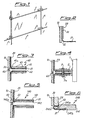
Figure 1 shows a perspective view of a façade of a building with glazed elements according to the present invention; -
Figure 2 shows a partial schematic cross-section through a glass element according to the invention; -
Figure 3 shows a partial schematic cross-section through a pair of glass elements engaged with gripping devices for securing thereof; -
Figure 4 shows a partial schematic cross-section through a pair of glass elements engaged with gripping devices constrained to the fixed parts of a building; -
Figure 5 shows a variation of an example of embodiment of the glass element according toFigure 1 and the corresponding gripping devices; -
Figure 6 shows a partial schematic cross-section through a further variation of an example of embodiment of the glass element according toFigure 1 and the corresponding gripping devices; -
Figure 7 shows a partial cross-section through a further variation of an example of embodiment of the glass element according toFigure 1 and the corresponding gripping devices; -
Figure 8 shows a partial schematic cross-section through a further variation of an example of embodiment of the glass element according toFigure 1 and the corresponding gripping devices; -
Figure 9 shows a partial schematic cross-section through a pair of glass elements engaged by means of a further embodiment of the gripping devices constrained to the fixed parts of a building; and -
Figure 10 shows a further example of embodiment of the gripping devices for constraining to fixed parts in the form of a cable. - As illustrated in
Figures 1 and 2 , a stratified glass element according to the present invention is composed essentially of a first transparent sheet ofglass 10, conventionally defined as external, and a second sheet ofglass 20, conventionally defined as internal, which are joined together by means of the positioning, in between, of anintermediate layer 30 of polymer material, for example of the ion plastic type, having optimum mechanical properties, in particular with regard to the instantaneous modulus of elasticity and the breakage strength. - Said
intermediate layer 30 is extended beyond the perimetral edge of theexternal sheet 10 and folded at a suitable angle inwards along asection 31 of suitable length. - The angle of curvature, relative to the surface of the glass element, of said folded
section 31 of theintermediate layer 30 is between 20° and 130° with a minimum radius of curvature of 1.5 mm. - According to preferred embodiments, said angle of curvature will be preferably between 80° and 105° and the radius of curvature between 4 and 20 mm.
- In order to allow passing-through and folding of the
intermediate layer 30, therear sheet 20 of the stratified glass element has a dimension smaller than the corresponding dimension of theexternal sheet 10. In a further embodiment, not shown, it is envisaged moreover that saidrear sheet 20 may have dimensions the same as those of thefront sheet 10 and may be provided with interruptions able to allow passing-through of theintermediate layer 30. -
Figure 3 shows a section of the façade in which two glass elements according to the present invention are arranged adjacent, with the joint between them sealed by means of mastic 60 of the compatible silicone-based type or equivalent material;Fig. 3 shows moreover themeans 40 for gripping thesection 31 of theintermediate layer 30 projecting inwards and, in the example, formed by twojaws section 31 by screw means 43 or the like. - It is envisaged, moreover, that the polymer material of the intermediate layer facilitates joining to the gripping means 40 following a heating and pressurisation treatment which activates the relative adhesion between the former and latter, increasing the strength of the joint.
- In the example according to
Figure 3 , thefirst jaw 41 extends towards the glass element along a section greater than that of thesecond jaw 42 and has aconvex section 41a corresponding to thecurvature 32 of theextended section 31, with which it combines in order to confer rigidity to the assembly. -
Figure 4 shows, moreover, an example of embodiment of the system for securing the glazed elements according toFigure 3 to a flange 2 integral with a fixed upright 1 of the building, said securing action being obtained by means of screw/female thread means 3/3a. -
Figure 5 shows a variation of embodiment of themeans 140 for gripping theprojecting section 31 of theintermediate layer 30; said gripping means 140 also consist in this case ofjaws 141;142 where thesecond jaw 142 extends towards the glass element so as to form a cavity inside which aseal 50 of soft material is housed so as to avoid direct contact between glass and metal. - Said
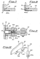
second jaw 142 also has, along the section corresponding to thecurvature 32, aconcave seat 142a for adaptation to the saidcurvature 32 of theprojecting section 31 of theintermediate layer 30.Figures 6 to 9 show further examples of embodiment of the glass element according to the present invention and the associated gripping devices. - In greater detail,
Figure 6 showsgripping devices 240 which in this case consist of afirst jaw 241 which has afirst seat 241a for housing the second internal sheet ofglass 20 and, on the opposite side, asecond seat 241b suitable for engagement with the second jaw 242a so as to allow clamping, by screw-type means or the like, of theintermediate layer 30 of the stratified glass element. - Conveniently, the dimensions of the
first seat 241a are such as to allow the positioning of astop 50 between glass and jaw. -
Figure 6 shows theexternal glass sheet 10 andinternal glass sheet 20 which have the same length, and the second jaw 242a is correspondingly extended towards the outside of the first jaw with a rounded form. - In
Figure 7 , on the other hand, theexternal sheet 10 is longer than theinternal sheet 20 and thesecond jaw 242b is correspondingly cut with a length substantially the same as that of thefirst jaw 241. - In the case of
Fig. 8 the long arm of the L is extended so that the short arm is arranged inside asuitable seat 10a of thesheet 10, so that thesheet 10 is retained also in the direction perpendicular to its plane. - In this case also
soft material 50 is arranged between the glass sheet and the metal jaw. -
Figure 9 shows a further variation of embodiment of the means for securing the glazed elements to aflange 102 integral with a fixed upright 101; said securing action is obtained by means of aninsert 102a of thesaid flange 102, which insert has a through-hole with afemale thread 102b coaxial with corresponding through-holes 241a in therespective jaws 241; saidfemale thread 102b is suitable for mating with a corresponding thread on afirst bolt 103a, the head of which rests on thefirst jaw 241 and the shank of which has internally a female thread suitable for mating with the threaded shank of asecond bolt 103, which is situated opposite to the first bolt and the head of which rests on the respectivefirst jaw 241 of the second glass element. - It is therefore obvious how with the glass element according to the invention it is possible to impart a high degree of continuity to the external glass surface which will be secured to the fixed structure without metal elements passing through the external surface of the glass, achieving, in addition to an improved aesthetic appearance, also a greater durability of the assembly since the securing device is protected from external agents.
- In addition to this, the glass element according to the present invention results in an improved versatility from an applicational point of view, allowing the formation of surfaces with any form and able to be associated with the most varying types of support structure, imparting moreover to the glass a high residual strength following possible breakage of the said glass.
- It is envisaged moreover that many variations may be introduced as regards the practical embodiment of the individual elements; hence, for example, the means for constraining to the fixed structure may be of the pin type arranged in the vicinity of the corners of the glass element or continuous and extending along at least two opposite edges of the stratified glass element; likewise the fixing means may be joined to structures both of the rigid type, such as frames made of steel, reinforced concrete, wood or glass, and of the deformable type, such as tensile structures, and/or cables, as for example shown in
Figure 10 where the fixed mounting element is precisely acable 201 having, mounted thereon, a cable-tensioning device 203,203a able to be arranged on opposite sides of thedevices 340 for gripping the stratified glass; saidgripping devices 340 also comprise afirst jaw 341 and asecond jaw 342; thefirst jaw 341 conveniently has aseat 345 able to allow the entry of thecable 201 and retaining means 345a able to prevent thegripping devices 340 from escaping in the transverse direction. - It is envisaged moreover that the stratified flat sheet may be of the blind and/or semi-transparent type for forming panels for closing openings and/or particular aesthetic effects.
Claims (32)
- Stratified flat element comprising an external sheet (10) and an internal sheet (20) joined together by means of an intermediate layer (30), said intermediate layer (30) is extended beyond at least one of the perimetral edges of the flat element and folded inwards over a section (31) of suitable length characterized in that it comprises devices (40;140;240;340) for gripping the folded section (31) of the intermediate layer (30) and in that said gripping devices lay internally relative to the external glass surface of said external sheet (10).
- Flat element according to Claim 1, characterized in that said intermediate layer consists of polymer material.
- Flat element according to Claim 1, characterized in that said intermediate layer (30) is extended beyond at least two perimetral edges of the flat element.
- Flat element according to Claim 3, characterized in that said two perimetral edges are opposite to each other.
- Flat element according to Claim 3, characterized in that said two perimetral edges are adjacent to each other.
- Flat element according to Claim 1, characterized in that the internal sheet (20) has a dimension smaller than that of the external sheet (10) at least in the position where the intermediate layer (30) is extended and folded.
- Flat element according to Claim 1, characterized in that the internal sheet (20) has interruptions able to allow passing-through and folding of the intermediate layer (30).
- Flat element according to Claim 1, characterized in that said extended or folded section (31) of the intermediate layer (30) is folded inwards at an angle of between 20° and 130°.
- Flat element according to Claim 8, characterized in that said angle of curvature is preferably between 80° and 105°.
- Flat element according to Claim 1, characterized in that the minimum radius of curvature of the extended and folded section (31) is 1.5 mm.
- Flat element according to Claim 10, characterized in that the radius of curvature is preferably between 4 and 20 mm.
- Flat element according to Claim 1, characterized in that said gripping devices (40;140;240;340) consist of a pair of jaws (41,42;141,142,142;241,242a,242b;241, 442b;241,341,342) at least one of which extends as far as the flat element.
- Flat element according to Claim 12, characterized in that said jaw (41;141) extending as far as the flat element has a convex section (41a) with a curvature corresponding to that (32) of the projecting section (31) of the intermediate layer (30).
- Flat element according to Claim 12, characterized in that one (42) of the two jaws (41,42) of, the pair has dimensions smaller than those of the first jaw (41).
- Flat element according to Claim 12, characterized in that said jaw (41;141) extending as far as the flat element has a first seat (241a) for housing the second internal sheet of glass (20) and, on the opposite side, a second seat (241b) suitable for engagement with the second jaw (242a) so as to clamp the intermediate layer (30) of the stratified glass.
- Flat element according to Claim 15, characterized in that the second jaw (242a) is extended with a rounded form beyond the edge of the first jaw.
- Flat element according to Claim 15, characterized in that the second jaw (242b) has a length substantially the same as that of the first jaw (241).
- Flat element according to Claim 12, characterized in that the second jaw (142) of the pair is extended towards the flat element and has a concave seat (142a) for adaptation to the said curvature (32) of the projecting section (31) of the intermediate layer (30).
- Flat element according to Claim 12, characterized in that the second jaw (442b;) of the pair has the shape of an L.
- Flat element according to Claim 19, characterized in that the long arm of the L is extended so that the short arm is arranged inside a suitable seat (10a) of the sheet (10).
- Flat element according to Claim 19, characterized in that the long arm of the L is extended so that the short arm is arranged beyond the sheet (10).
- Flat element according to Claim 12, characterized in that the second jaw (142) is extended towards the flat element so as to form a gap inside which a seal (50) is housed.
- Flat element according to Claim 1, characterized in that said gripping elements have through-holes suitable for engagement with corresponding means (3,3a;103,103a) for constraining to corresponding fixed support parts.
- Flat element according to Claim 23, characterized in that said through-holes are formed on the first jaw of the pair.
- Flat element according to 23, characterized in that said constraining means consist of a bolt (3) and a nut (3a).
- Flat element according to Claim 23, characterized in that said constraining means consist of a first bolt (103a) having, formed on its shank, a thread and a female thread suitable for mating with the threaded shank of a second bolt (103) situated opposite the first bolt.
- Flat element according to Claim 26, characterized in that said thread is suitable for mating with the female thread (102b) of an insert (102a) integral with the fixed means (102) for supporting the flat element.
- Flat element according to Claim 24, characterized in that said through-hole (345) is open in the longitudinal direction towards the support structure and is associated with corresponding means (345a) for closing the opening.
- Flat element according to Claim 1, characterized in that the joint between the extended and folded section (31) of the intermediate layer (30) and the said gripping means (40) is performed by means of adhesion of the former to the latter.
- Flat element according to Claim 1, characterized in that said sheets (10,20) are transparent.
- Flat element according to Claim 1, characterized in that at least one of said sheets (10,20) is opaque.
- Use of the flat element according to claim 1 as a covering for surfaces of buildings
Applications Claiming Priority (2)
| Application Number | Priority Date | Filing Date | Title |
|---|---|---|---|
| ITMI20040534 | 2004-03-19 | ||
| IT000534A ITMI20040534A1 (en) | 2004-03-19 | 2004-03-19 | FLAT LAYER ELEMENT WITH EXTENDED AND FOLDED INTERMEDIATE LAYER AT LEAST ONE PERIMETER EDGE OF THE ELEMENT ITEMS |
Publications (2)
| Publication Number | Publication Date |
|---|---|
| EP1577481A1 EP1577481A1 (en) | 2005-09-21 |
| EP1577481B1 true EP1577481B1 (en) | 2011-01-19 |
Family
ID=34835601
Family Applications (1)
| Application Number | Title | Priority Date | Filing Date |
|---|---|---|---|
| EP05075628A Active EP1577481B1 (en) | 2004-03-19 | 2005-03-16 | Stratified flat element with intermediate layer extended and folded beyond at least one perimetral edge of the said flat element |
Country Status (4)
| Country | Link |
|---|---|
| EP (1) | EP1577481B1 (en) |
| AT (1) | ATE496195T1 (en) |
| DE (1) | DE602005025953D1 (en) |
| IT (1) | ITMI20040534A1 (en) |
Family Cites Families (4)
| Publication number | Priority date | Publication date | Assignee | Title |
|---|---|---|---|---|
| US5778629A (en) * | 1995-09-28 | 1998-07-14 | Howes; Stephen E. | Impact resistant window |
| US5960606A (en) * | 1997-02-28 | 1999-10-05 | Dlubak; Francis Charles | Penetration resistant window |
| FR2781415B1 (en) * | 1998-07-24 | 2000-09-01 | Saint Gobain Vitrage | SAFETY SHEET GLAZING |
| US6737151B1 (en) * | 1999-04-22 | 2004-05-18 | E. I. Du Pont De Nemours And Company | Glass laminates having improved structural integrity against severe impacts |
-
2004
- 2004-03-19 IT IT000534A patent/ITMI20040534A1/en unknown
-
2005
- 2005-03-16 EP EP05075628A patent/EP1577481B1/en active Active
- 2005-03-16 AT AT05075628T patent/ATE496195T1/en not_active IP Right Cessation
- 2005-03-16 DE DE602005025953T patent/DE602005025953D1/en active Active
Also Published As
| Publication number | Publication date |
|---|---|
| ITMI20040534A1 (en) | 2004-06-19 |
| EP1577481A1 (en) | 2005-09-21 |
| DE602005025953D1 (en) | 2011-03-03 |
| ATE496195T1 (en) | 2011-02-15 |
Similar Documents
| Publication | Publication Date | Title |
|---|---|---|
| RU2012129954A (en) | FRAME ASSEMBLY FOR SHEET MATERIAL | |
| JP7016167B2 (en) | Profile for tightening glass panels | |
| ES2211070T3 (en) | GLASS CONSTRUCTION ELEMENT TO FORM A SECTION OR ELEMENT OF WALL, ROOF, OR SELF-SUPPORTING COVER. | |
| KR100974922B1 (en) | Member for fixing insulation panel and method for fixing insulation panel using the same | |
| ES2295310T3 (en) | UNION DEVICE, DECK DEVICE AND SEPARATOR ELEMENT. | |
| JP2006241695A (en) | Supporting structure of glass pane | |
| EP1577481B1 (en) | Stratified flat element with intermediate layer extended and folded beyond at least one perimetral edge of the said flat element | |
| JP2010519102A (en) | Method for assembling a glazing integrally with its support by gluing and means for realizing this method | |
| ES2690419T3 (en) | Procedure and fixing element to install a sun visor on a glazed part | |
| KR20090037738A (en) | Reinforce structure for window frame | |
| AU2003267369A1 (en) | Supporting framework for a facade | |
| EP2694307B1 (en) | Adjustement device for mounting the windshield glass on the vehicle body | |
| JP2004124648A (en) | Support structure of glass pane | |
| CZ301126B6 (en) | Frameless tempered glass panel | |
| JP4710731B2 (en) | Property exterior material | |
| JP5396058B2 (en) | Glass support structure | |
| KR200413016Y1 (en) | Rib glass and patch type glass structure comprised of the same glass material | |
| ES2927096T3 (en) | Light element and process for manufacturing the light element | |
| KR101033609B1 (en) | System for fixing a panel made of brittle material | |
| KR200254586Y1 (en) | Coupling portion for partioning panel of light weight | |
| KR101541501B1 (en) | Fixing bracket for light weight stone panel | |
| JP3646760B2 (en) | Attachment structure for multi-layer glass | |
| US20090065157A1 (en) | Connection device and a method of forming a panel assembly | |
| AU2019257523A1 (en) | An edge seal flashing | |
| JP2014122474A (en) | Curtain wall |
Legal Events
| Date | Code | Title | Description |
|---|---|---|---|
| PUAI | Public reference made under article 153(3) epc to a published international application that has entered the european phase |
Free format text: ORIGINAL CODE: 0009012 |
|
| AK | Designated contracting states |
Kind code of ref document: A1 Designated state(s): AT BE BG CH CY CZ DE DK EE ES FI FR GB GR HU IE IS IT LI LT LU MC NL PL PT RO SE SI SK TR |
|
| AX | Request for extension of the european patent |
Extension state: AL BA HR LV MK YU |
|
| 17P | Request for examination filed |
Effective date: 20060228 |
|
| AKX | Designation fees paid |
Designated state(s): AT BE BG CH CY CZ DE DK EE ES FI FR GB GR HU IE IS IT LI LT LU MC NL PL PT RO SE SI SK TR |
|
| AXX | Extension fees paid |
Extension state: YU Payment date: 20060228 Extension state: AL Payment date: 20060228 Extension state: BA Payment date: 20060228 Extension state: MK Payment date: 20060228 |
|
| 17Q | First examination report despatched |
Effective date: 20080404 |
|
| GRAP | Despatch of communication of intention to grant a patent |
Free format text: ORIGINAL CODE: EPIDOSNIGR1 |
|
| GRAS | Grant fee paid |
Free format text: ORIGINAL CODE: EPIDOSNIGR3 |
|
| GRAA | (expected) grant |
Free format text: ORIGINAL CODE: 0009210 |
|
| AK | Designated contracting states |
Kind code of ref document: B1 Designated state(s): AT BE BG CH CY CZ DE DK EE ES FI FR GB GR HU IE IS IT LI LT LU MC NL PL PT RO SE SI SK TR |
|
| AX | Request for extension of the european patent |
Extension state: AL BA MK YU |
|
| REG | Reference to a national code |
Ref country code: GB Ref legal event code: FG4D |
|
| RAP2 | Party data changed (patent owner data changed or rights of a patent transferred) |
Owner name: COOPSETTE SOC. COOP. |
|
| REG | Reference to a national code |
Ref country code: CH Ref legal event code: EP |
|
| REG | Reference to a national code |
Ref country code: IE Ref legal event code: FG4D |
|
| REF | Corresponds to: |
Ref document number: 602005025953 Country of ref document: DE Date of ref document: 20110303 Kind code of ref document: P |
|
| REG | Reference to a national code |
Ref country code: DE Ref legal event code: R096 Ref document number: 602005025953 Country of ref document: DE Effective date: 20110303 |
|
| PGFP | Annual fee paid to national office [announced via postgrant information from national office to epo] |
Ref country code: MC Payment date: 20110331 Year of fee payment: 7 |
|
| REG | Reference to a national code |
Ref country code: NL Ref legal event code: VDEP Effective date: 20110119 |
|
| LTIE | Lt: invalidation of european patent or patent extension |
Effective date: 20110119 |
|
| PG25 | Lapsed in a contracting state [announced via postgrant information from national office to epo] |
Ref country code: GR Free format text: LAPSE BECAUSE OF FAILURE TO SUBMIT A TRANSLATION OF THE DESCRIPTION OR TO PAY THE FEE WITHIN THE PRESCRIBED TIME-LIMIT Effective date: 20110420 Ref country code: LT Free format text: LAPSE BECAUSE OF FAILURE TO SUBMIT A TRANSLATION OF THE DESCRIPTION OR TO PAY THE FEE WITHIN THE PRESCRIBED TIME-LIMIT Effective date: 20110119 Ref country code: PT Free format text: LAPSE BECAUSE OF FAILURE TO SUBMIT A TRANSLATION OF THE DESCRIPTION OR TO PAY THE FEE WITHIN THE PRESCRIBED TIME-LIMIT Effective date: 20110519 Ref country code: SE Free format text: LAPSE BECAUSE OF FAILURE TO SUBMIT A TRANSLATION OF THE DESCRIPTION OR TO PAY THE FEE WITHIN THE PRESCRIBED TIME-LIMIT Effective date: 20110119 Ref country code: IS Free format text: LAPSE BECAUSE OF FAILURE TO SUBMIT A TRANSLATION OF THE DESCRIPTION OR TO PAY THE FEE WITHIN THE PRESCRIBED TIME-LIMIT Effective date: 20110519 Ref country code: ES Free format text: LAPSE BECAUSE OF FAILURE TO SUBMIT A TRANSLATION OF THE DESCRIPTION OR TO PAY THE FEE WITHIN THE PRESCRIBED TIME-LIMIT Effective date: 20110430 |
|
| PGFP | Annual fee paid to national office [announced via postgrant information from national office to epo] |
Ref country code: LU Payment date: 20110504 Year of fee payment: 7 Ref country code: FR Payment date: 20110414 Year of fee payment: 7 |
|
| PG25 | Lapsed in a contracting state [announced via postgrant information from national office to epo] |
Ref country code: PL Free format text: LAPSE BECAUSE OF FAILURE TO SUBMIT A TRANSLATION OF THE DESCRIPTION OR TO PAY THE FEE WITHIN THE PRESCRIBED TIME-LIMIT Effective date: 20110119 Ref country code: FI Free format text: LAPSE BECAUSE OF FAILURE TO SUBMIT A TRANSLATION OF THE DESCRIPTION OR TO PAY THE FEE WITHIN THE PRESCRIBED TIME-LIMIT Effective date: 20110119 Ref country code: SI Free format text: LAPSE BECAUSE OF FAILURE TO SUBMIT A TRANSLATION OF THE DESCRIPTION OR TO PAY THE FEE WITHIN THE PRESCRIBED TIME-LIMIT Effective date: 20110119 Ref country code: BG Free format text: LAPSE BECAUSE OF FAILURE TO SUBMIT A TRANSLATION OF THE DESCRIPTION OR TO PAY THE FEE WITHIN THE PRESCRIBED TIME-LIMIT Effective date: 20110419 Ref country code: NL Free format text: LAPSE BECAUSE OF FAILURE TO SUBMIT A TRANSLATION OF THE DESCRIPTION OR TO PAY THE FEE WITHIN THE PRESCRIBED TIME-LIMIT Effective date: 20110119 Ref country code: AT Free format text: LAPSE BECAUSE OF FAILURE TO SUBMIT A TRANSLATION OF THE DESCRIPTION OR TO PAY THE FEE WITHIN THE PRESCRIBED TIME-LIMIT Effective date: 20110119 Ref country code: CY Free format text: LAPSE BECAUSE OF FAILURE TO SUBMIT A TRANSLATION OF THE DESCRIPTION OR TO PAY THE FEE WITHIN THE PRESCRIBED TIME-LIMIT Effective date: 20110119 |
|
| PGFP | Annual fee paid to national office [announced via postgrant information from national office to epo] |
Ref country code: BE Payment date: 20110415 Year of fee payment: 7 Ref country code: GB Payment date: 20110428 Year of fee payment: 7 |
|
| PGFP | Annual fee paid to national office [announced via postgrant information from national office to epo] |
Ref country code: IT Payment date: 20110428 Year of fee payment: 7 |
|
| PG25 | Lapsed in a contracting state [announced via postgrant information from national office to epo] |
Ref country code: EE Free format text: LAPSE BECAUSE OF FAILURE TO SUBMIT A TRANSLATION OF THE DESCRIPTION OR TO PAY THE FEE WITHIN THE PRESCRIBED TIME-LIMIT Effective date: 20110119 Ref country code: DK Free format text: LAPSE BECAUSE OF FAILURE TO SUBMIT A TRANSLATION OF THE DESCRIPTION OR TO PAY THE FEE WITHIN THE PRESCRIBED TIME-LIMIT Effective date: 20110119 |
|
| REG | Reference to a national code |
Ref country code: CH Ref legal event code: PL |
|
| PLBE | No opposition filed within time limit |
Free format text: ORIGINAL CODE: 0009261 |
|
| STAA | Information on the status of an ep patent application or granted ep patent |
Free format text: STATUS: NO OPPOSITION FILED WITHIN TIME LIMIT |
|
| PG25 | Lapsed in a contracting state [announced via postgrant information from national office to epo] |
Ref country code: SK Free format text: LAPSE BECAUSE OF FAILURE TO SUBMIT A TRANSLATION OF THE DESCRIPTION OR TO PAY THE FEE WITHIN THE PRESCRIBED TIME-LIMIT Effective date: 20110119 Ref country code: RO Free format text: LAPSE BECAUSE OF FAILURE TO SUBMIT A TRANSLATION OF THE DESCRIPTION OR TO PAY THE FEE WITHIN THE PRESCRIBED TIME-LIMIT Effective date: 20110119 Ref country code: CZ Free format text: LAPSE BECAUSE OF FAILURE TO SUBMIT A TRANSLATION OF THE DESCRIPTION OR TO PAY THE FEE WITHIN THE PRESCRIBED TIME-LIMIT Effective date: 20110119 |
|
| 26N | No opposition filed |
Effective date: 20111020 |
|
| REG | Reference to a national code |
Ref country code: IE Ref legal event code: MM4A |
|
| PG25 | Lapsed in a contracting state [announced via postgrant information from national office to epo] |
Ref country code: IE Free format text: LAPSE BECAUSE OF NON-PAYMENT OF DUE FEES Effective date: 20110316 Ref country code: DE Free format text: LAPSE BECAUSE OF NON-PAYMENT OF DUE FEES Effective date: 20111001 Ref country code: CH Free format text: LAPSE BECAUSE OF NON-PAYMENT OF DUE FEES Effective date: 20110331 Ref country code: LI Free format text: LAPSE BECAUSE OF NON-PAYMENT OF DUE FEES Effective date: 20110331 |
|
| REG | Reference to a national code |
Ref country code: DE Ref legal event code: R119 Ref document number: 602005025953 Country of ref document: DE Effective date: 20111001 |
|
| REG | Reference to a national code |
Ref country code: AT Ref legal event code: MK05 Ref document number: 496195 Country of ref document: AT Kind code of ref document: T Effective date: 20110119 |
|
| BERE | Be: lapsed |
Owner name: COOPSETTE SOC. COOP. Effective date: 20120331 |
|
| PG25 | Lapsed in a contracting state [announced via postgrant information from national office to epo] |
Ref country code: MC Free format text: LAPSE BECAUSE OF NON-PAYMENT OF DUE FEES Effective date: 20120331 |
|
| GBPC | Gb: european patent ceased through non-payment of renewal fee |
Effective date: 20120316 |
|
| REG | Reference to a national code |
Ref country code: FR Ref legal event code: ST Effective date: 20121130 |
|
| PG25 | Lapsed in a contracting state [announced via postgrant information from national office to epo] |
Ref country code: BE Free format text: LAPSE BECAUSE OF NON-PAYMENT OF DUE FEES Effective date: 20120331 Ref country code: GB Free format text: LAPSE BECAUSE OF NON-PAYMENT OF DUE FEES Effective date: 20120316 Ref country code: FR Free format text: LAPSE BECAUSE OF NON-PAYMENT OF DUE FEES Effective date: 20120402 |
|
| PG25 | Lapsed in a contracting state [announced via postgrant information from national office to epo] |
Ref country code: IT Free format text: LAPSE BECAUSE OF NON-PAYMENT OF DUE FEES Effective date: 20120316 |
|
| PG25 | Lapsed in a contracting state [announced via postgrant information from national office to epo] |
Ref country code: TR Free format text: LAPSE BECAUSE OF FAILURE TO SUBMIT A TRANSLATION OF THE DESCRIPTION OR TO PAY THE FEE WITHIN THE PRESCRIBED TIME-LIMIT Effective date: 20110119 |
|
| PG25 | Lapsed in a contracting state [announced via postgrant information from national office to epo] |
Ref country code: HU Free format text: LAPSE BECAUSE OF FAILURE TO SUBMIT A TRANSLATION OF THE DESCRIPTION OR TO PAY THE FEE WITHIN THE PRESCRIBED TIME-LIMIT Effective date: 20110119 |
|
| PG25 | Lapsed in a contracting state [announced via postgrant information from national office to epo] |
Ref country code: LU Free format text: LAPSE BECAUSE OF NON-PAYMENT OF DUE FEES Effective date: 20120316 |