EP1577212B1 - Tragflügel mit einer Vorrichtung zur Strömungsregulierung - Google Patents
Tragflügel mit einer Vorrichtung zur Strömungsregulierung Download PDFInfo
- Publication number
- EP1577212B1 EP1577212B1 EP04022521A EP04022521A EP1577212B1 EP 1577212 B1 EP1577212 B1 EP 1577212B1 EP 04022521 A EP04022521 A EP 04022521A EP 04022521 A EP04022521 A EP 04022521A EP 1577212 B1 EP1577212 B1 EP 1577212B1
- Authority
- EP
- European Patent Office
- Prior art keywords
- aerofoil
- passage
- inlet
- fitting
- outlet
- Prior art date
- Legal status (The legal status is an assumption and is not a legal conclusion. Google has not performed a legal analysis and makes no representation as to the accuracy of the status listed.)
- Expired - Lifetime
Links
- 239000000463 material Substances 0.000 claims description 11
- 238000005553 drilling Methods 0.000 claims description 7
- 230000003628 erosive effect Effects 0.000 claims description 7
- 238000000034 method Methods 0.000 claims description 7
- 238000004519 manufacturing process Methods 0.000 claims description 3
- 239000000853 adhesive Substances 0.000 description 6
- 230000001070 adhesive effect Effects 0.000 description 6
- 238000000465 moulding Methods 0.000 description 5
- 229920002635 polyurethane Polymers 0.000 description 2
- 239000004814 polyurethane Substances 0.000 description 2
- 239000012779 reinforcing material Substances 0.000 description 2
- 239000011347 resin Substances 0.000 description 2
- 229920005989 resin Polymers 0.000 description 2
- 230000015572 biosynthetic process Effects 0.000 description 1
- 150000001875 compounds Chemical class 0.000 description 1
- 239000004033 plastic Substances 0.000 description 1
- 229920003023 plastic Polymers 0.000 description 1
Images
Classifications
-
- B—PERFORMING OPERATIONS; TRANSPORTING
- B64—AIRCRAFT; AVIATION; COSMONAUTICS
- B64C—AEROPLANES; HELICOPTERS
- B64C27/00—Rotorcraft; Rotors peculiar thereto
- B64C27/32—Rotors
- B64C27/46—Blades
-
- B—PERFORMING OPERATIONS; TRANSPORTING
- B64—AIRCRAFT; AVIATION; COSMONAUTICS
- B64C—AEROPLANES; HELICOPTERS
- B64C2230/00—Boundary layer controls
- B64C2230/04—Boundary layer controls by actively generating fluid flow
-
- B—PERFORMING OPERATIONS; TRANSPORTING
- B64—AIRCRAFT; AVIATION; COSMONAUTICS
- B64C—AEROPLANES; HELICOPTERS
- B64C2230/00—Boundary layer controls
- B64C2230/20—Boundary layer controls by passively inducing fluid flow, e.g. by means of a pressure difference between both ends of a slot or duct
-
- B—PERFORMING OPERATIONS; TRANSPORTING
- B64—AIRCRAFT; AVIATION; COSMONAUTICS
- B64C—AEROPLANES; HELICOPTERS
- B64C2230/00—Boundary layer controls
- B64C2230/22—Boundary layer controls by using a surface having multiple apertures of relatively small openings other than slots
-
- B—PERFORMING OPERATIONS; TRANSPORTING
- B64—AIRCRAFT; AVIATION; COSMONAUTICS
- B64C—AEROPLANES; HELICOPTERS
- B64C2230/00—Boundary layer controls
- B64C2230/28—Boundary layer controls at propeller or rotor blades
-
- Y—GENERAL TAGGING OF NEW TECHNOLOGICAL DEVELOPMENTS; GENERAL TAGGING OF CROSS-SECTIONAL TECHNOLOGIES SPANNING OVER SEVERAL SECTIONS OF THE IPC; TECHNICAL SUBJECTS COVERED BY FORMER USPC CROSS-REFERENCE ART COLLECTIONS [XRACs] AND DIGESTS
- Y02—TECHNOLOGIES OR APPLICATIONS FOR MITIGATION OR ADAPTATION AGAINST CLIMATE CHANGE
- Y02T—CLIMATE CHANGE MITIGATION TECHNOLOGIES RELATED TO TRANSPORTATION
- Y02T50/00—Aeronautics or air transport
- Y02T50/10—Drag reduction
Definitions
- This invention related to an aerofoil having a flow control device commonly known as an air jet vortex generator or AJVG.
- An AJVG typically includes a passage within the aerofoil, the passage opening at an upper aerofoil surface of the aerofoil, whereby in use, air from the passage passes through the opening to affect airflow over the upper surface of the aerofoil over at least a range of incidence angles. Examples are illustrated in US-A-6283406 , US-A-05813625 and in JP-A-07300098 .
- An AJVG may be provided to energise boundary airflow over the upper aerofoil surface, to assist the airflow in overcoming a large pressure gradient, which particularly but not exclusively may be encountered at high incidence angles.
- an AJVG may be used to delay stalling, to increase lift and reduce drag on the aerofoil as the aerofoil moves through the air.
- the invention has particularly but not exclusively been developed for use on an aircraft wing, which may be either a fixed wing or a rotating wing such as a helicopter blade.
- the position and shape of the opening in the upper aerofoil surface is critical.
- Helicopter blades at least, typically are fabricated by moulding in compound materials typically including resin and reinforcing materials. Such materials do not readily lend themselves to the formation of accurately shaped openings, and moreover, the provision of a discontinuity such as an opening, can lead to erosion and other undesirable aerofoil wear, particularly in the region of the opening.
- a discontinuity such as an opening
- the fitting may be made in a durable material which is more resistant to erosion than the materials of the body, and fitted to the aerofoil surface so that the interface between the fitting and the upper aerofoil surface is smooth, i.e. so that no or a minimal discontinuity is provided.
- the invention has particularly but not exclusively been developed for a so-called passive AJVG, i.e. the device includes an inlet opening for air at or closely adjacent to a lower aerofoil surface, the air passing into the inlet opening of the passage and flowing to the passage outlet at the upper aerofoil surface afforded by the outlet fitting, by the movement of the aerofoil through the air.
- the flow control device includes an inlet fitting which is secured relative to the aerofoil, desirably at an inlet position at or closely adjacent the lower aerofoil surface, the inlet fitting including a surface part which lies contiguously with the surrounding lower aerofoil surface so there is no or only a minimal discontinuity where the surface part and the surrounding lower aerofoil surface interface, the surface part of the inlet fitting further including an inlet opening which communicates with the passage within the body of the aerofoil.
- a desired shape of inlet opening too may be provided and the inlet fitting may again be made in a durable material which is resistant to erosion, i.e. is more durable than the material of the body, and fitted to the aerofoil surface so that the interface between the fitting and the adjacent aerofoil surface is smooth, i.e. so that no or a minimal discontinuity is provided.
- the passage in the aerofoil is provided subsequent to moulding the aerofoil, e.g. by drilling.
- the drilling process may provide a pair of passage parts which intersect non co-axially. Thus air flowing through the passage needs to undergo an abrupt change of direction which is undesirable.
- the aerofoil of the invention includes a flexible conduit within the passage, the conduit extending to the passage outlet.
- the outlet fitting and the flexible conduit may be monolithic, alternatively these may be interconnected.
- the flexible conduit may have a cross section which is ideal for the most efficient air flow through the passage, such as round, whilst the outlet provided by the outlet fitting may be of an alternative desired shape to achieve an optimum affect on the airflow over the upper aerofoil surface.
- the flexible conduit which may be a plastic such as polyurethane, thus will allow optimised airflow through the passage, as the conduit may smooth any otherwise abrupt changes of direction of the airflow.
- the flexible conduit may be integral with the inlet fitting or connected to the inlet fitting as desired.
- the outlet fitting includes a surface part shaped so that when the fitting is secured relative to the upper surface of the aerofoil, the surface part lies substantially contiguously with the surrounding aerofoil upper surface, and a hollow spigot part which extends into the passage for interconnection to the flexible conduit
- the inlet fitting includes a surface part which when the inlet fitting is secured at or adjacent to the lower aerofoil surface, lies substantially contiguously with the surrounding aerofoil surface, and a hollow spigot part which extends into the passage for connection to the flexible conduit.
- the aerofoil may be a fixed wing of an aircraft or a rotor blade of a main sustaining or tail rotor of a helicopter.
- a plurality of flow control devices are provided along a -leading edge of the aerofoil.
- the aerofoil of the second aspect of the invention may have any of the features of the aerofoil of the first aspect of the invention.
- the method may include providing both the inlet and outlet fittings and providing between the inlet and outlet fittings, a flexible conduit which is integral or connected to one or each of the inlet and outlet fittings.
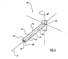
- a main sustaining rotor assembly 10 of a helicopter has four blades, one of which is shown at 11, and the positions of the other blades being indicated by lines.
- the blade 11 is an aerofoil over which in use, air flows to provide lift.
- the rotor blade 11 extends from a root end 12 which typically is a rotor head or hub, outwardly along a blade span to a tip which is indicated at 13.
- a tip 13 In practice the tip 13 would be of a complex configuration but is shown in figure 1 schematically only to indicate the aerofoil cross section.
- the blade 11 has an aerofoil body 14, with a leading edge 15, a trailing edge 16, an upper aerofoil surface 14 between the leading and trailing edges 15, 16, and a lower aerofoil surface 20 between the leading and trailing edges 15, 16.
- the blade 11 may be feathered about a blade axis A and thus the angle of incidence of the blade 11 to the air through which the blade 11 in use moves, may vary.
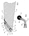
- a plurality of flow control devices namely passive AJVGs.
- Each of these includes a passage 22 within the aerofoil body 14, the passage 22 opening at the upper aerofoil surface 18 of the aerofoil 11, air in use, from the passage 22 passing through an outlet opening 21 to affect airflow over the upper surface 18 of the aerofoil 11 over at least a range of incidence angles.
- the flow control devices each include an outlet fitting 24 which in this example includes a surface part 25 with the outlet opening 21 provided therein, the outlet opening 21 communicating with the passage 22 via a hollow spigot part 26 of the outlet fitting 24.
- the outlet fitting 24 is made in a material which is resistant to erosion or other wear at least at the outlet opening 21, and is secured relative to the upper surface 18 of the aerofoil 11, e.g. by adhesive.
- the surface part 25 is configured so that it lies contiguously with the surrounding upper aerofoil surface 18 so there is no or only a minimal discontinuity where the surface part 25 and the surrounding aerofoil surface 18 interface, indicated at 27.
- the spigot part 26 receives within it, an end of a flexible conduit 28 which will be discussed in more detail below.
- the passive AJVG flow control device includes an inlet opening 30 for air, which is positioned at or closely adjacent to the lower aerofoil surface 20, in this example closely adjacent the leading edge 15 of the blade 11.
- the flow control device includes an inlet fitting 31 which in this example includes a surface part 35 and a hollow spigot part 36.
- the inlet opening 30 is provided in the surface part 35 and communicates with the passage 22 via the hollow spigot part 36 of the inlet fitting 31.
- the inlet fitting 31 is made in a material which is resistant to erosion or other wear at the inlet opening 30, and is secured relative to the inlet position at or closely adjacent to the lower surface 20 of the aerofoil 11, e.g. by adhesive.
- the surface part 35 of the inlet fitting 31 is configured so that it lies contiguously with the surrounding aerofoil surface 20 so there is no or only a minimal discontinuity where the surface part 35 and the surrounding lower aerofoil surface 20 interface, indicated at 37.
- the spigot part 36 of the inlet fitting 31 is connected to the flexible conduit 28.
- the aerofoil body 14 in this example is made by moulding in resin and reinforcing materials.
- the passage 22 is provided subsequent to moulding, e.g. by drilling.
- the passage 22 typically is not straight, but has two parts 22a and 22b, which are not co-axial, but are inclined, necessarily so that the passage 22 can extend from a desired inlet position 30 to a desired outlet position 21, and each passage part 22a, 22b may be straight and may be provided by drilling.
- airflow through the passage 22 from the inlet 30 to the outlet 21 would involve an abrupt change of direction where the passage parts 22a, 22b intersect.
- the provision of the flexible conduit 28 smooths the intersection for the airflow, thus reducing losses and improving efficiency.
- the spigot part 26 of the outlet fitting 24 receives the end of the flexible conduit 28 within, as does the spigot part 36 of the inlet fitting 31, although the inlet fitting 31 has an inner abutment so that the position of the flexible conduit 28 relative to the inlet fitting 31 may be fixed.
- the flexible conduit 28 may be connected to the respective inlet and outlet fittings 31, 24 otherwise, although a method of installing the flow control device will be described for the particular configuration as seen in the drawings.
- the passage 22 may be provided by drilling the respective passage parts 22b, 22a from the upper aerofoil surface outlet position 21, and from the inlet position 30 at or adjacent the lower aerofoil surface 20, respectively.
- the aerofoil surface 18, 20 around the respective passage outlet 21 and inlet 30 is then cut away to produce a respective recess to receive the respective surface part 25 of the outlet fitting 24 and surface part 35 of the inlet fitting 31, so that the surface parts 25, 35 can be secured, e.g. by adhesive, so as to lie contiguously with the surrounding aerofoil surface 18, 20.
- the flexible conduit 28 may be already secured to the spigot part 36 of the inlet fitting 31 or may be subsequently secured, e.g. by adhesive, after feeding into the passage 28 from the outlet opening 21.
- the flexible conduit 28 may extend outwardly of the upper surface 18 of the aerofoil 11 at this time.
- outlet fitting 21 is passed over the flexible conduit, which is then connected inside the spigot part 26 of the outlet fitting 24, e.g. by adhesive, and the outlet fitting 24 is secured relative to the upper surface 18 of the aerofoil 11 as shown, again, desirably by adhesive.
- the flexible conduit 28 in this example may be of polyurethane for example, and of round cross section for most efficient airflow through the passage 22.
- the inlet opening 30 provided through the hollow spigot 36 may be of larger cross section than the flexible conduit 28 as shown, but the cross section of the actual opening 30 in the surface part 35 of the inlet fitting 31 need not be circular but may be of any desired shape for most efficient passage of air into the opening 30.
- the actual outlet opening 21 formed in the surface part 25 of the outlet fitting 24 may typically be a slot or other shape as desired for affecting the airflow over the upper aerofoil surface 18, optimally.
- the flexible conduit 28 may be integral or monolithic with at least one of the inlet 31 and outlet 24 fittings.
- Flow control devices may be retro-fitted to existing aerofoils, or provided during aerofoil fabrication, subsequent to moulding the aerofoil body 14.
Landscapes
- Engineering & Computer Science (AREA)
- Mechanical Engineering (AREA)
- Aviation & Aerospace Engineering (AREA)
- Structures Of Non-Positive Displacement Pumps (AREA)
- Air-Flow Control Members (AREA)
Claims (16)
- Tragfläche (11) mit einem Körper (14) und wenigstens einer Strömungsbeeinflussungsvorrichtung, wobei die Strömungsbeeinflussungsvorrichtung einen Durchgang (22) im Körper (14) der Tragfläche (11) und einen Durchgangsauslass (21) an einer oberen Tragflächenoberfläche (18) der Tragfläche (11) aufweist, wodurch im Gebrauch Luft von dem Durchgang (22) durch den Durchgangsauslass (21) hindurchströmt, um die Luftströmung über die obere Oberfläche (18) der Tragfläche (11) über wenigstens einen Bereich von Anstellwinkeln zu beeinflussen, dadurch gekennzeichnet, dass eine Auslassarmatur bereitgestellt ist, die einen Oberflächenteil (25) mit einer durchgehenden Öffnung aufweist, und die Auslassarmatur mit Oberflächenteil (25) und durchgehender Öffnung relativ zur oberen Oberfläche (18) der Tragfläche (11) befestigt ist, so dass der Oberflächenteil (25) an die umgebende obere Tragflächenoberfläche (18) angrenzend liegt, so dass an der Stoßstelle zwischen dem Oberflächenteil (25) und der umgebenden oberen Tragflächenoberfläche (18) keine oder nur eine minimale Diskontinuität besteht, und die durchgehende Öffnung der Auslassarmatur mit dem Durchgang (22) im Körper (14) der Tragfläche (11) kommuniziert und den Durchgangsauslass (21) bereitstellt.
- Tragfläche (11) nach Anspruch 1, dadurch gekennzeichnet, dass die Armatur aus einem haltbaren Material hergestellt ist, das erosionsbeständiger ist als das Material des Körpers (14), und an der oberen Tragflächenoberfläche (18) angebracht ist, so dass die Grenzfläche zwischen der Armatur und der oberen Tragflächenoberfläche (18) glatt ist.
- Tragfläche nach Anspruch 1 oder Anspruch 2, dadurch gekennzeichnet dass die Strömungsbeeinflussungsvorrichtung einen Durchgangseinlass (30) für Luft an oder eng neben einer unteren Tragflächenoberfläche (20) aufweist, wobei die Luft durch die Bewegung der Tragfläche (11) durch die Luft in den Durchgangs einlass (30) einströmt und zu der durch die Auslassarmatur gebildeten Öffnung (21) an der oberen Tragflächenaberfläche (18) strömt.
- Tragfläche nach Anspruch 3, dadurch gekennzeichnet, dass die Strömungsbeeinflussungsvorrichtung eine Einlassarmatur aufweist die relativ zur Tragfläche (11) an einer Einlassposition (31) an oder eng neben der unteren Tragflächenoberfläche (20) befestigt ist, wobei die Einlassarmatur einen Oberflächenteil (35) aufweist, der an die umgebende untere Tragflächenoberfläche (20) angrenzend liegt, so dass es an der Stoßstelle zwischen dem Oberflächenteil (35) und der umgebenden unteren Tragflächenoberfläche (20) keine oder nur eine minimale Diskontinuität gibt, wobei der Oberflächenteil (35) der Einlassarmatur ferner eine Einlassöffung (30) aufweist, die mit dem Durchgang (22) im Körper (14) der Tragfläche (11) kommuniziert.
- Tragfläche (11) nach Anspruch 4, dadurch gekennzeichnet, dass die Einlassarmatur aus einem haltbaren Material hergestellt ist, das erosionsbeständig ist, und an der unteren Tragflächenoberfläche (20) angebracht ist, so dass die Grenzfläche zwischen der Armatur und der unteren Tragflächenoberfläche (20) glatt ist.
- Tragfläche nach einem der vorhergehenden Ansprüche, dadurch gekennzeichnet, dass in dem Durchgang (22) ein flexibler Kanal (28) bereitgestellt ist, wobei der Kanal (28) zum Durchgangsauslass (21) verläuft.
- Tragfläche nach Anspruch 6, dadurch gekennzeichnet, dass die Auslassarmatur und der flexible Kanal (28) miteinander verbunden sind und/oder der flexible Kanal mit der Einlassarmatur, wenn vorhanden, verbunden ist.
- Tragfläche nach Anspruch oder Anspruch 7, dadurch gekennzeichnet, dass die Auslassarmatur einen hohlen Muffenteil (35) hat, durch welchen die durchgehende Öffnung verläuft, wobei sich der Muffenteil (35) zur Zusammenfügung mit dem flexiblen Kanal (28) in den Durchgang (22) erstreckt.
- Tragfläche nach einem der Ansprüche 6 bis 8, wenn abhängig von Anspruch 4, dadurch gekennzeichnet, dass die Einlassarmatur einen hohlen Muffenteil (36) hat, der sich zur Verbindung mit dem flexiblen Kanal (28) in den Durchgang (22) erstreckt.
- Tragfläche nach einem der vorhergehenden Ansprüche, die ein Starrflügel eines Flugzeugs oder ein Rotorblatt eines Haupttrag- oder Heckrotors eines Drehflügelflugzeugs ist.
- Tragfläche nach Anspruch 10, dadurch gekennzeichnet, dass entlang einer Vorderkante (15) der Tragfläche (11) mehrere Strömungsbeeinflussungsvorrichtungen bereitgestellt sind.
- Tragfläche mit einem Körper (14) und wenigstens einer Strömungsbeeinflussungsvorrichtung, wobei die Strömungsbeeinflussungsvorrichtung einen Durchgang (22) im Körper (14) der Tragfläche (11) und einen Durchgangseinlass (30) an einer Position an oder neben einer unteren Tragflächenoberfläche (20) der Tragfläche (11) ausweist, wodurch im Gebrauch Luft in den Durchgangseinlass (30) einströmt und zu einem Auslass (21) an einer oberen Tragflächenoberfläche (18) strömt, um die Luftströmung über die obere Oberfläche (18) der Tragfläche (11) über wenigstens einen Bereich von Anstellwinkeln zu beeinflussen, dadurch gekennzeichnet, dass eine Einlassarmatur bereitgestellt ist, die einen Oberflächenteil (35) mit einer durchgehenden Öffnung aufweist, und die Einlassarmatur mit Oberflächenteil (35) und durchsehender Öffnung an der Einlassposition (30) befestigt ist, so dass der Oberflächenteil (35) an die umgebende untere Tragflächenoberfläche (20) angrenzend liegt, so dass es an der Stoßstelle (37) zwischen dem Oberflächenteil (35) und der umgebenden unteren Tragflächenoberfläche (20) keine oder nur eine minimale Diskontinuität gibt, und die durchgehende Öffnung der Einlassarmatur mit dem Durchgang (22) im Körper (14) der Tragfläche (11) kommuniziert und den Durchgangseinlass (30) bereitstellt.
- Flugzeug mit einer Tragfläche (11), dadurch gekennzeichnet, dass die Tragfläche (11) einem der vorhergehenden Ansprüche gemäß ist.
- Verfahren zum Herstellen einer Tragfläche (11) nach einem der vorhergehenden Ansprüche, dadurch gekennzeichnet, dass das Verfahren die folgenden Schritte aufweist: Bereitstellen eines Durchgangs (22) in einem Tragflächenkörper (14) mit einer oberen Tragflächenoberfläche (18) und einer unteren Tragflächenoberfläche (20), wobei der Durchgang (22) von einer Einlassposition (30) an oder neben der unteren Tragflächenoberfläche (20) und einem Durchgangsauslass (21) an der oberen Tragflächenoberfläche (18) verläuft, und Befestigen einer Auslass armatur relativ zur oberen Oberfläche (18) der Tragfläche (11) und/oder das Befestigen einer Einlassarmatur an der Einlassposition (30) an oder neben der unteren Tragflächonoberfläche (20), und wobei die Auslassarmatur einen Oberflächenteil (25) aufweist, der, wenn relativ zur oberen Oberfläche (18) der Tragfläche (11) befestigt, an die umgebende obere Tragflächenoberfläche (18) angrenzend liegt, so dass es an der Stoßstelle (27) zwischen dem Oberflächenteil (25) und der umgebenden oberen Tragflächenoberfläche (18) keine oder nur eine minimale Diskontinuität gibt, wobei der Oberflächenteil (25) der Auslassarmatur ferner eine durchgehende Öffnung aufweist, die mit dem Durchgang (22) im Körper (14) der Tragfläche (11) kommuniziert, so dass die durchgehende Öffnung, wenn die Auslassarmatur befestigt ist, den Durchgangsauslass (21) bildet, und die Einlassarmatur, wenn relativ zur unteren Oberfläche der Tragfläche befestigt, einen Oberflächenteil (35) ausweist, der an die umgebende untere Tragflächenoberfläche (20) angrenzend liegt, so dass es an der Stoßstelle (37) zwischen dem Oberflächenteil (35) und der umgebenden unteren Tragflächenoberfläche (20) keine oder nur eine minimale Diskontinuität gibt, wobei der Oberflächenteil (35) der Einlassarmatur ferner eine durchgehende Öffnung aufweist, die mit dem Durchgang (22) im Körper (14) der Tragfläche (11) kommuniziert, so dass die durchgehende Öffnung, wenn die Einlassarmatur befestigt ist, den Durchgangseinlass (30) bildet.
- Verfahren nach Anspruch 14, dadurch gekennzeichnet, dass das Verfahren das Bereitstellen von Einlass- und Auslassarmaturen und das Bereitstellen eines flexiblen Kanals (18) zwischen den Einlass- und Auslassarmaturen, der mit einer oder jeder der Einlass- und Auslassarmaturen einstückig ausgestaltet oder verbunden ist, aufweist.
- Verfahren nach Anspruch 14 oder Anspruch 15, das die folgenden Schritte aufweist: das Bereitstellen eines ersten Durchgangsteils (22a) durch Bohren von der unteren Tragflächenoberfläche (20) und das Bereitstellen eines zweiten Durchgangsteils (22b) durch Bohren von einer oberen Tragflächenoberfläche (20), und wobei der erste und der zweite Durchgangsteil (22a, 22b) relativ zueinander geneigt sind und einander schneiden.
Applications Claiming Priority (2)
| Application Number | Priority Date | Filing Date | Title |
|---|---|---|---|
| GB0405843 | 2004-03-16 | ||
| GBGB0405843.4A GB0405843D0 (en) | 2004-03-16 | 2004-03-16 | Improvements in or relating to aerofoils |
Publications (3)
| Publication Number | Publication Date |
|---|---|
| EP1577212A2 EP1577212A2 (de) | 2005-09-21 |
| EP1577212A3 EP1577212A3 (de) | 2005-12-21 |
| EP1577212B1 true EP1577212B1 (de) | 2008-05-07 |
Family
ID=32117749
Family Applications (1)
| Application Number | Title | Priority Date | Filing Date |
|---|---|---|---|
| EP04022521A Expired - Lifetime EP1577212B1 (de) | 2004-03-16 | 2004-09-22 | Tragflügel mit einer Vorrichtung zur Strömungsregulierung |
Country Status (6)
| Country | Link |
|---|---|
| US (1) | US7264444B2 (de) |
| EP (1) | EP1577212B1 (de) |
| JP (1) | JP4713160B2 (de) |
| CA (1) | CA2484787C (de) |
| DE (1) | DE602004013535D1 (de) |
| GB (1) | GB0405843D0 (de) |
Families Citing this family (17)
| Publication number | Priority date | Publication date | Assignee | Title |
|---|---|---|---|---|
| DE102006058650B4 (de) * | 2006-12-11 | 2009-11-19 | Eads Deutschland Gmbh | Tragflügel eines Flugzeugs |
| US7748958B2 (en) * | 2006-12-13 | 2010-07-06 | The Boeing Company | Vortex generators on rotor blades to delay an onset of large oscillatory pitching moments and increase maximum lift |
| US8746624B2 (en) | 2008-05-23 | 2014-06-10 | David Birkenstock | Boundary layer control system and methods thereof |
| US8651813B2 (en) * | 2009-05-29 | 2014-02-18 | Donald James Long | Fluid dynamic body having escapelet openings for reducing induced and interference drag, and energizing stagnant flow |
| US8449255B2 (en) * | 2010-03-21 | 2013-05-28 | Btpatent Llc | Wind turbine blade system with air passageway |
| US8016560B2 (en) | 2010-09-17 | 2011-09-13 | General Electric Company | Wind turbine rotor blade with actuatable airfoil passages |
| US8128364B2 (en) * | 2010-12-07 | 2012-03-06 | General Electric Company | Wind turbine rotor blade with porous window and controllable cover member |
| US8240993B2 (en) * | 2011-01-04 | 2012-08-14 | General Electric Company | System and method of manipulating a boundary layer across a rotor blade of a wind turbine |
| GB201103122D0 (en) * | 2011-02-23 | 2011-04-06 | Airbus Uk Ltd | Composite structure |
| EP2549097A1 (de) * | 2011-07-20 | 2013-01-23 | LM Wind Power A/S | Windturbinenschaufel mit hubregulierenden Mitteln |
| US8960609B2 (en) | 2011-12-15 | 2015-02-24 | Lockheed Martin Corporation | Minimally intrusive wingtip vortex wake mitigation using inside-mold-line surface modifications |
| US20140215998A1 (en) * | 2012-10-26 | 2014-08-07 | Honeywell International Inc. | Gas turbine engines with improved compressor blades |
| GB2517124B (en) * | 2013-05-13 | 2015-12-09 | Ge Aviat Systems Ltd | Method for diagnosing a trailing edge flap fault |
| HUP1600523A2 (en) * | 2016-09-07 | 2018-03-28 | Attila Nyiri | Regulation of blades for airscrew, blower or wind turbine by holes, slots and notches |
| US11912395B2 (en) * | 2016-09-07 | 2024-02-27 | Attila NYIRI | Propeller and propeller blade |
| HU231494B1 (hu) * | 2020-10-14 | 2024-04-28 | Róbert 40% Círus | Légcsavar és széles légcsavar-lapát |
| CN112722248A (zh) * | 2021-02-22 | 2021-04-30 | 上海交通大学 | 一种机翼无气源振荡射流流动控制装置 |
Family Cites Families (20)
| Publication number | Priority date | Publication date | Assignee | Title |
|---|---|---|---|---|
| GB304973A (en) | 1928-05-08 | 1929-01-31 | Edouard Ferdinand Albert | Improvements in wings for aeroplanes and like aircraft |
| US1887148A (en) * | 1930-05-02 | 1932-11-08 | Ganahl Carl De | Aeroplane propulsion |
| GB510546A (en) | 1938-02-07 | 1939-08-03 | Alfred Richard Weyl | Improvements relating to high-lift aerofoils |
| GB573555A (en) | 1943-05-19 | 1945-11-26 | Giles Eyre Blake | Improvements in airscrews |
| US3512414A (en) | 1968-05-23 | 1970-05-19 | Rosemount Eng Co Ltd | Slotted airfoil sensor housing |
| US3767322A (en) * | 1971-07-30 | 1973-10-23 | Westinghouse Electric Corp | Internal cooling for turbine vanes |
| US4169567A (en) * | 1974-12-13 | 1979-10-02 | Tamura Raymond M | Helicopter lifting and propelling apparatus |
| DE3241456A1 (de) | 1982-11-10 | 1984-05-10 | Messerschmitt-Bölkow-Blohm GmbH, 8000 München | Einrichtung zur verminderung von boeenlasten |
| DE3345154C2 (de) | 1983-12-14 | 1987-02-12 | Messerschmitt-Bölkow-Blohm GmbH, 8012 Ottobrunn | Tragflügel für Luftfahrzeuge |
| DE3629910A1 (de) * | 1986-09-03 | 1988-03-17 | Mtu Muenchen Gmbh | Metallisches hohlbauteil mit einem metallischen einsatz, insbesondere turbinenschaufel mit kuehleinsatz |
| JPH07300098A (ja) * | 1994-05-06 | 1995-11-14 | Mitsubishi Heavy Ind Ltd | 低騒音型ブレード |
| US5479400A (en) | 1994-06-06 | 1995-12-26 | Metricom, Inc. | Transceiver sharing between access and backhaul in a wireless digital communication system |
| US6142425A (en) * | 1995-08-22 | 2000-11-07 | Georgia Institute Of Technology | Apparatus and method for aerodynamic blowing control using smart materials |
| US5813625A (en) * | 1996-10-09 | 1998-09-29 | Mcdonnell Douglas Helicopter Company | Active blowing system for rotorcraft vortex interaction noise reduction |
| US6109566A (en) | 1999-02-25 | 2000-08-29 | United Technologies Corporation | Vibration-driven acoustic jet controlling boundary layer separation |
| GB9911924D0 (en) | 1999-05-21 | 1999-07-21 | Adaptive Broadband Ltd | A method and system for wireless connection to a wide area network |
| US6283406B1 (en) * | 1999-09-10 | 2001-09-04 | Gte Service Corporation | Use of flow injection and extraction to control blade vortex interaction and high speed impulsive noise in helicopters |
| US6654616B1 (en) | 1999-09-27 | 2003-11-25 | Verizon Laboratories Inc. | Wireless area network having flexible backhauls for creating backhaul network |
| US6728514B2 (en) | 2000-09-08 | 2004-04-27 | Wi-Lan Inc. | Scalable wireless network topology systems and methods |
| JP4171869B2 (ja) | 2001-09-05 | 2008-10-29 | ソニー株式会社 | ヘテロダイン受信機 |
-
2004
- 2004-03-16 GB GBGB0405843.4A patent/GB0405843D0/en not_active Ceased
- 2004-09-22 DE DE602004013535T patent/DE602004013535D1/de not_active Expired - Lifetime
- 2004-09-22 EP EP04022521A patent/EP1577212B1/de not_active Expired - Lifetime
- 2004-10-06 US US10/958,589 patent/US7264444B2/en not_active Expired - Lifetime
- 2004-10-14 CA CA2484787A patent/CA2484787C/en not_active Expired - Lifetime
-
2005
- 2005-01-06 JP JP2005001808A patent/JP4713160B2/ja not_active Expired - Lifetime
Also Published As
| Publication number | Publication date |
|---|---|
| US7264444B2 (en) | 2007-09-04 |
| US20050207895A1 (en) | 2005-09-22 |
| DE602004013535D1 (de) | 2008-06-19 |
| GB0405843D0 (en) | 2004-04-21 |
| JP4713160B2 (ja) | 2011-06-29 |
| CA2484787C (en) | 2012-05-15 |
| JP2005263201A (ja) | 2005-09-29 |
| EP1577212A3 (de) | 2005-12-21 |
| EP1577212A2 (de) | 2005-09-21 |
| CA2484787A1 (en) | 2005-09-16 |
Similar Documents
| Publication | Publication Date | Title |
|---|---|---|
| EP1577212B1 (de) | Tragflügel mit einer Vorrichtung zur Strömungsregulierung | |
| KR101950862B1 (ko) | 윈드 터빈 회전자 블레이드 | |
| US8579594B2 (en) | Wind turbine blade with submerged boundary layer control means | |
| US8469672B2 (en) | Blade for a wind turbine rotor | |
| EP2198153B1 (de) | Windturbinenschaufel mit überkreuzende nebenkanäle umfassenden versenkten grenzschichtsteuermitteln | |
| EP3137291B1 (de) | Windturbinenschaufel und zugehöriges herstellungsverfahren | |
| CN106471246B (zh) | 用于空气动力学壳体扩展件的附接的型材楔形件 | |
| CN102865188B (zh) | 风力涡轮机叶片 | |
| CN109642541A (zh) | 风力涡轮机叶片上的涡流发生器装置的真空辅助安装 | |
| EP3027892B1 (de) | Schaufel für eine windturbine und verfahren zur herstellung einer schaufel für eine windturbine | |
| EP3317180B1 (de) | Hubschrauber mit gegendrehmomentsystem, zugehöriges kit und verfahren | |
| US7891610B2 (en) | Rotary flap | |
| WO2013020959A1 (en) | Blade for a rotor of a wind turbine and a wind turbine | |
| CN208593491U (zh) | 一种降低桨涡干扰效应的桨叶前缘开孔装置 | |
| EP3176425A1 (de) | Anordnung von tragflügelförmigem körper und lärmverringernder umzahnung und damit ausgestattete windturbine | |
| CN102257269A (zh) | 风力涡轮机控制表面铰链 | |
| KR101620924B1 (ko) | 풍력 발전기용 결합형 블레이드 | |
| GB2588258A (en) | Wind turbine blade with a flow controlling element |
Legal Events
| Date | Code | Title | Description |
|---|---|---|---|
| PUAI | Public reference made under article 153(3) epc to a published international application that has entered the european phase |
Free format text: ORIGINAL CODE: 0009012 |
|
| AK | Designated contracting states |
Kind code of ref document: A2 Designated state(s): AT BE BG CH CY CZ DE DK EE ES FI FR GB GR HU IE IT LI LU MC NL PL PT RO SE SI SK TR |
|
| AX | Request for extension of the european patent |
Extension state: AL HR LT LV MK |
|
| PUAL | Search report despatched |
Free format text: ORIGINAL CODE: 0009013 |
|
| AK | Designated contracting states |
Kind code of ref document: A3 Designated state(s): AT BE BG CH CY CZ DE DK EE ES FI FR GB GR HU IE IT LI LU MC NL PL PT RO SE SI SK TR |
|
| AX | Request for extension of the european patent |
Extension state: AL HR LT LV MK |
|
| 17P | Request for examination filed |
Effective date: 20060315 |
|
| AKX | Designation fees paid |
Designated state(s): DE FR GB IT |
|
| 17Q | First examination report despatched |
Effective date: 20060407 |
|
| GRAP | Despatch of communication of intention to grant a patent |
Free format text: ORIGINAL CODE: EPIDOSNIGR1 |
|
| GRAS | Grant fee paid |
Free format text: ORIGINAL CODE: EPIDOSNIGR3 |
|
| GRAA | (expected) grant |
Free format text: ORIGINAL CODE: 0009210 |
|
| AK | Designated contracting states |
Kind code of ref document: B1 Designated state(s): DE FR GB IT |
|
| REG | Reference to a national code |
Ref country code: GB Ref legal event code: FG4D |
|
| REF | Corresponds to: |
Ref document number: 602004013535 Country of ref document: DE Date of ref document: 20080619 Kind code of ref document: P |
|
| PLBE | No opposition filed within time limit |
Free format text: ORIGINAL CODE: 0009261 |
|
| STAA | Information on the status of an ep patent application or granted ep patent |
Free format text: STATUS: NO OPPOSITION FILED WITHIN TIME LIMIT |
|
| 26N | No opposition filed |
Effective date: 20090210 |
|
| REG | Reference to a national code |
Ref country code: FR Ref legal event code: PLFP Year of fee payment: 12 |
|
| REG | Reference to a national code |
Ref country code: FR Ref legal event code: PLFP Year of fee payment: 13 |
|
| REG | Reference to a national code |
Ref country code: FR Ref legal event code: PLFP Year of fee payment: 14 |
|
| REG | Reference to a national code |
Ref country code: FR Ref legal event code: PLFP Year of fee payment: 15 |
|
| REG | Reference to a national code |
Ref country code: DE Ref legal event code: R081 Ref document number: 602004013535 Country of ref document: DE Owner name: LEONARDO UK LTD, GB Free format text: FORMER OWNER: WESTLAND HELICOPTERS LTD., YEOVIL, SOMERSET, GB |
|
| REG | Reference to a national code |
Ref country code: GB Ref legal event code: 732E Free format text: REGISTERED BETWEEN 20220609 AND 20220615 |
|
| P01 | Opt-out of the competence of the unified patent court (upc) registered |
Effective date: 20230530 |
|
| PGFP | Annual fee paid to national office [announced via postgrant information from national office to epo] |
Ref country code: IT Payment date: 20230921 Year of fee payment: 20 Ref country code: GB Payment date: 20230801 Year of fee payment: 20 |
|
| PGFP | Annual fee paid to national office [announced via postgrant information from national office to epo] |
Ref country code: FR Payment date: 20230928 Year of fee payment: 20 Ref country code: DE Payment date: 20230920 Year of fee payment: 20 |
|
| REG | Reference to a national code |
Ref country code: DE Ref legal event code: R071 Ref document number: 602004013535 Country of ref document: DE |
|
| PG25 | Lapsed in a contracting state [announced via postgrant information from national office to epo] |
Ref country code: GB Free format text: LAPSE BECAUSE OF EXPIRATION OF PROTECTION Effective date: 20240921 |
|
| REG | Reference to a national code |
Ref country code: GB Ref legal event code: PE20 Expiry date: 20240921 |
|
| PG25 | Lapsed in a contracting state [announced via postgrant information from national office to epo] |
Ref country code: GB Free format text: LAPSE BECAUSE OF EXPIRATION OF PROTECTION Effective date: 20240921 |