EP1577174A1 - Hochtemperaturverarbeitungsverfahren für aufblasvorrichtung - Google Patents
Hochtemperaturverarbeitungsverfahren für aufblasvorrichtung Download PDFInfo
- Publication number
- EP1577174A1 EP1577174A1 EP03786274A EP03786274A EP1577174A1 EP 1577174 A1 EP1577174 A1 EP 1577174A1 EP 03786274 A EP03786274 A EP 03786274A EP 03786274 A EP03786274 A EP 03786274A EP 1577174 A1 EP1577174 A1 EP 1577174A1
- Authority
- EP
- European Patent Office
- Prior art keywords
- inflators
- inflator
- air bag
- treatment
- high temperature
- Prior art date
- Legal status (The legal status is an assumption and is not a legal conclusion. Google has not performed a legal analysis and makes no representation as to the accuracy of the status listed.)
- Withdrawn
Links
Images
Classifications
-
- F—MECHANICAL ENGINEERING; LIGHTING; HEATING; WEAPONS; BLASTING
- F23—COMBUSTION APPARATUS; COMBUSTION PROCESSES
- F23G—CREMATION FURNACES; CONSUMING WASTE PRODUCTS BY COMBUSTION
- F23G7/00—Incinerators or other apparatus for consuming industrial waste, e.g. chemicals
- F23G7/003—Incinerators or other apparatus for consuming industrial waste, e.g. chemicals for used articles
-
- B—PERFORMING OPERATIONS; TRANSPORTING
- B09—DISPOSAL OF SOLID WASTE; RECLAMATION OF CONTAMINATED SOIL
- B09B—DISPOSAL OF SOLID WASTE NOT OTHERWISE PROVIDED FOR
- B09B3/00—Destroying solid waste or transforming solid waste into something useful or harmless
- B09B3/30—Destroying solid waste or transforming solid waste into something useful or harmless involving mechanical treatment
- B09B3/35—Shredding, crushing or cutting
-
- B—PERFORMING OPERATIONS; TRANSPORTING
- B09—DISPOSAL OF SOLID WASTE; RECLAMATION OF CONTAMINATED SOIL
- B09B—DISPOSAL OF SOLID WASTE NOT OTHERWISE PROVIDED FOR
- B09B3/00—Destroying solid waste or transforming solid waste into something useful or harmless
- B09B3/40—Destroying solid waste or transforming solid waste into something useful or harmless involving thermal treatment, e.g. evaporation
-
- B—PERFORMING OPERATIONS; TRANSPORTING
- B60—VEHICLES IN GENERAL
- B60R—VEHICLES, VEHICLE FITTINGS, OR VEHICLE PARTS, NOT OTHERWISE PROVIDED FOR
- B60R21/00—Arrangements or fittings on vehicles for protecting or preventing injuries to occupants or pedestrians in case of accidents or other traffic risks
- B60R21/02—Occupant safety arrangements or fittings, e.g. crash pads
- B60R21/16—Inflatable occupant restraints or confinements designed to inflate upon impact or impending impact, e.g. air bags
- B60R21/26—Inflatable occupant restraints or confinements designed to inflate upon impact or impending impact, e.g. air bags characterised by the inflation fluid source or means to control inflation fluid flow
- B60R21/264—Inflatable occupant restraints or confinements designed to inflate upon impact or impending impact, e.g. air bags characterised by the inflation fluid source or means to control inflation fluid flow using instantaneous generation of gas, e.g. pyrotechnic
- B60R21/2644—Inflatable occupant restraints or confinements designed to inflate upon impact or impending impact, e.g. air bags characterised by the inflation fluid source or means to control inflation fluid flow using instantaneous generation of gas, e.g. pyrotechnic using only solid reacting substances, e.g. pellets, powder
-
- F—MECHANICAL ENGINEERING; LIGHTING; HEATING; WEAPONS; BLASTING
- F23—COMBUSTION APPARATUS; COMBUSTION PROCESSES
- F23G—CREMATION FURNACES; CONSUMING WASTE PRODUCTS BY COMBUSTION
- F23G2201/00—Pretreatment
- F23G2201/60—Separating
-
- F—MECHANICAL ENGINEERING; LIGHTING; HEATING; WEAPONS; BLASTING
- F23—COMBUSTION APPARATUS; COMBUSTION PROCESSES
- F23G—CREMATION FURNACES; CONSUMING WASTE PRODUCTS BY COMBUSTION
- F23G2900/00—Special features of, or arrangements for incinerators
- F23G2900/70—Incinerating particular products or waste
- F23G2900/7001—Air bags or seat belt pre-tensioners
Definitions
- the present invention relates to a high temperature treating method for inflators for an air bag in which inflators for an air bag for an automobile accommodating gas generating materials therein are heated at a temperature equal to or higher than igniting temperatures of the gas generating materials to treat the inflators, and a metal recovering method.
- inflators for an air bag For treatment of inflators for an air bag, it is also required to ensure safety during treatment and prevent harmful substances from being generated in addition to igniting accommodated gas generating materials by a thermal treatment and recovering/reusing useful resources such as metals.
- inflators for an air bag there are about 20 different types of inflators including one for a driver's side, one for a front passenger's side, one for a side collision, one for a curtain air bag and the like, and these inflators are different in shape, size, materials or the like. Further, even equivalent inflators for a driver's side are different in shape, size, material and the like depending on respective manufacturing companies, and it is therefore difficult to apply a standardized treatment method to these inflators.
- JP-A 11-101422 is mentioned.
- An object of the present invention is to provide a high temperature treating method for inflators for an air bag which can treat an inflator for an air bag, such as failure products produced in a manufacturing process safely and efficiently and can promote recovery and reuse of useful materials, and a metal recovering method for inflators for an air bag utilizing the high temperature treating method.
- the present invention provides a high temperature treating method for inflators for an air bag comprising:
- the present invention includes the above-described steps as basic steps, and besides that other steps can be added, as needed, the order of the steps can be properly modified according to actual circumstances of a work site.
- the present invention further provides a method for recovering metals constituting inflators after the treatment has been terminated by a high temperature treating method for inflators for an air bag according to any one of claims 1 to 12, wherein a step of cooling the interior of the thermally treating tower after the thermally treating step is terminated and then melting the inflators after the inflators are taken out is provided.
- Inflators for an air bag which are treatment subjects in the present invention, include all inflators required for treatment from various reasons, for example, failure products produced in a manufacturing step, returned articles from an automobile manufacturer or a module manufacturer, stock products after manufacturing thereof have been stopped, inflators which have been removed from scrapped vehicles.
- treatment can be performed safely with an excellent workability, and besides that generation of harmful substances such as dioxins can be remarkably suppressed and recovery and reuse of useful materials can be promoted.
- a treatment in a step of cutting and removing wire harnesses connected for inflator activation is performed.
- the treatment in (A) step is conducted before (E) step of conducting heating treatment.
- Inflators for an air bag which are treatment subjects in the present invention include failure products produced in the manufacturing process as described above and the like, and these inflators include ones with various shapes, sizes and materials mixedly, but all the inflators are mounted with wire harnesses for inflator actuation.
- the wire harness is connected to an igniter housed in the inflator and it is for allowing electrical current conduction from a power source (a battery) to activate the igniter at an actuation of the inflator.
- a power source a battery
- the wire harness is cut in advance at a recovery of the inflator, the inflator is transported to a treatment equipment in a state that it has a wire harness attached thereto and in a state that it is received in an exclusive inflator case since there might be a possibility that an igniter causes malfunction and a gas generating material burns during transportation of the inflator or the like.
- the wire harness is constituted by covering conductive wires with plastic material, and when it is treated at a high temperature as it is, dioxins may be generated, so that the wire harness is cut and removed in this step. It is desirable to conduct the cutting at a root portion (a portion connected to the inflator) of the wire harness as much as possible.
- treatment in a step of removing plastic parts housed in the inflator is performed.
- the treatment in (B) step is performed before (E) step of conducting thermal treatment.
- This step is for performing grouping according to respective groups of parts made from identical material in advance in view of the entire workability.
- an outer shell container (a housing, a diffuser shell, a closure shell and the like) made of metal usually occupies the dominant ratio of constituent metals of each inflator, inflators are grouped to respective groups of metals constituting the outer shell containers.
- the inflators after grouped are received in respective receiving boxes.
- the inflators are of mechanical types, when they are packed in a large container at random, there occurs a possibility that, when igniters come in contact with each other, or when an igniter comes in contact with another metal, the igniter may cause malfunction so that a gas generating material might be ignited and burnt. Therefore, in order to avoid such an incident, it is desirable that the inflators may be accommodated in a receiving container made of plastic or the like such that igniters of inflators do not come in contact with each other.
- This step is for separating the inflators for every same shape in advance in view of the entire workability like (C) step.
- inflators are grouped into disk-shaped inflators and cylinder-shape inflators.
- many of inflators for a driver's side have the disk shape
- many of the side inflators and curtain inflators have the cylinder shape.
- Both of the disk-shaped inflator and the cylinder-shape inflator are used as the inflator for a front passenger's side.
- a step of grouping the inflators into pyrotechnic ones and hybrid-type ones can further be added.
- (D) step it is desirable to receive the inflators after grouped into receiving boxes for the same reason as (C) step.
- the treatments in (C) and (D) steps may be performed before (A) and (B) steps, but it is preferable that the treatments are conducted after the steps (A) and (B) in order to performs the treatments efficiently in view of the work flow. Further, the treatments in (C) and (D) steps are performed before (E) step of conducting heating treatment.
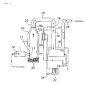
- a thermally treating tower 10 preferably constitutes one treating system (a thermal treatment equipment) as a whole by being attached with an exhaust gas tube 16, an inflator charging port 12, a combustion furnace (for example, a combination of a high calorie burner and a low calorie burner) 14, a cooling tower of exhaust gas 17, a shower for cooling exhaust gas 19, a cooling tower tank 18, and a gas discharging tube 26 along with the thermally treating tower 10.
- the numerals 13 and 25 denote wire meshes, punching metals, gratings made of metal such as iron or the like
- the numeral 20 denotes a heat exchanger
- the numeral 22 denotes a cooling tower
- the numeral 24 denotes a pump.
- a metal partition wall 11 (with reference to Fig. 1) having the same function as that disclosed in Fig. 1 and the like in JP-A 11-101442 (a protection function of an inner wall of the heating and activating tower 10) can be provided inside the heating and activating tower 10.
- another apparatus or system can be combined thereto, as needed.
- Inflators 30 charged form the inflator charging port 12 into the thermally treating tower 10 are heated at a predetermined temperature or more to ignite and burn gas generating materials housed therein.
- the thermal treatment temperature in the thermally treating tower 10 is a temperature at which the gas generating materials housed in the inflators 30 burn but the main metal constituting the inflators 30 does not melt.
- the temperature at which the gas generating material burns is a temperature equal to or more than an ignition temperature of the gas generating material, and the ignition temperature varies depending on the composition of the gas generating material.
- the ignition temperature of an ordinary gas generating material is in the range of about 150 to 500°C, but since there might be a possibility that when the temperature in the thermally treating tower becomes excessively high, an inner wall of the thermally treating furnace 10 is damaged, the temperature inside the thermally treating tower 10 is preferably in the range of 150 to 800°C, more preferably in the range of 150 to 700°C.
- the ignition temperature of the gas generating material may be about 150°C.
- the temperature at which the main metals constituting the inflators do not melt varies depending on the material of the inflator, but since the material is ordinarily aluminum, iron or stainless steel, a temperature lower than a temperature at which these metals melt is set to an upper limit temperature.
- a temperature lower than a temperature at which these metals melt is set to an upper limit temperature.
- aluminum it is preferable to set the temperature in the range of 450 to 550°C
- iron and stainless steel it is preferable to set the temperature to 550 to 700°C. It is desirable to consider a point of preventing damage to the thermally treating furnace 10 due to heat like the above.
- the combustion gas is discharged from the exhaust gas tube 16 connected to a ceiling portion of the thermally treating tower 10, it is cooled inside the cooling tower 17 by water spaying due to shower for cooling 19, and it is guided into water inside the cooling tower tank 18. A gas staying in the cooling tower tank 18 is discharged from the gas discharging tube 26 into the atmosphere.
- a temperature inside the thermally treating tower 10 is preliminarily elevated by the combustion furnace 14 up to a temperature (for example, 650°C) at which the gas generating materials inside the inflators 30 burn but the main metals constituting the inflators 30 do not melt and the elevated temperature is maintained.
- a temperature for example, 650°C
- a method for causing the high calorie burner and the low calorie burner to burn simultaneously, and stopping the high calorie burner at a time point at which the temperature reaches a predetermined temperature to cause only the low calorie burner to burn can be applied. At this time, an air blowing amount into the thermally treating tower 10 may be adjusted simultaneously.
- the above-described predetermined temperature is maintained until the treatment of the inflators 30 is terminated. Even in the case of a method where the inflators 30 are charged plural times and the inflators 30 are treated in the charging order, the above predetermined temperature is maintained until the treatment of the inflator(s) charged latest is terminated.
- the maintaining time of the predetermined temperature in the heating-treatment step is determined such that a time equal to or more than at least a time required for treatment of the inflators is secured by confirming both or one of a time elapsing before all gas generating materials, enhancers, chemical substances such as a primer inside an inflators are activated (in the hybrid inflators, a time elapsing before gases charged therein rupture the rupturable plates to discharge the charged gases, namely, a time required for treatment of the inflators), this time being obtained by a heating test where an inflator is exposed to a temperature atmosphere to be treated in the heating and activating tower 10, and a time required for treatment confirmed by a bomb fire test of the inflator (a test for observing an actuation state of an inflator in a state where the inflator is exposed in a flame).
- the maintaining time of the predetermined temperature in the thermal treatment step is preferably 1 to 100 times a time required after the inflators are charged, or after the inflators are charged latest when charging of inflators are divisionally conducted plural times, before the treatment of the inflators is terminated, more preferably 3 to 30 times.
- the treating method in the thermally treating tower 10 besides the above, a method in which the temperature inside the thermally treating tower 10 is elevated in the vicinity of an ignition temperature of a gas generating material in advance and performing a temperature is risen rapidly after charging inflators 30; or a method in which the normal temperature or a temperature sufficiently lower than an ignition temperature of a gas generating material inside the heating and activating tower 10 is maintained and a temperature is gradually risen after charging inflators 30, can be adopted.
- the partitioning means 25 comprising a wire mesh, a punching metal, a metal-made grating or the like is removably mounted between the heating and activating tower 10 and the exhaust gas tube 16, so that the inflators 30 are prevented from jumping out of the thermally treating tower 10.
- the partition means 25 is removably mounted to a flange portion provided at an inner wall surface 10a of the thermally treating tower 10 or an inner wall surface 16a of the exhaust gas tube 16 by using bolts and nuts. Further, by providing a partition means 13 functioning in the same manner as the partition means 25 between the thermally treating tower 10 and the combustion furnace 14, the inflator(s) 30 is prevented from jumping into the combustion furnace 14.
- the metal recovering method is a treatment method for inflators, which is conducted subsequent to the high temperature treating method for inflators explained in the Embodiment 1.
- the inflators there are ones whose outer shell containers have an apparently sealed structure (which is not a completely sealed structure and has a nearly sealed structure where a clearance(s) is fine) or ones which have a structure in which water is easily entered and stayed.
- the inflators are considered in view of materials thereof, in inflators where a main metal constituting an inflator is iron or stainless steel, and when the inflators are considered in view of kinds of the inflators, as hybrid inflators, there are ones required for cutting.
- inflators having such a structure are subjected to a melting treatment in the next step for recovering metal, there might be a possibility that inflators having an apparently sealed structure cause expansion and explosion to scatter molten metal, and inflators in which water is entered and stays may cause water vapor explosion. Even in either case, it is expected that the facility is damaged, or danger is posed to the body of a worker in certain circumstances. For this reason, the inflators are cut off to prevent such an accident from occurring.
- a method for cutting is not limited to a specific one, but, for example, a shearing machine or a high speed cutting machine having a cutting blade rotating at a high speed, such as a resinoid cutting whetstone, a chip saw or the like, can be used.
- the cut state of the inflator may be one which does not cause such an accident as described above, and the inflator can be ordinarily cut to have the outer shell container divided from a central portion thereof.
- the high temperature treating method and the metal recovering method of the present invention can be applied as a treating method for various inflators such as an inflator for an air bag for a driver's side, an inflator for an air bag for a front passenger's side, an inflator for a side air bag, an inflator for a curtain air bag, an inflator for a knee-bolster, an inflator for an inflatable seat belt, an inflator for a tubular system and an inflator for a pretensioner.
- various inflators such as an inflator for an air bag for a driver's side, an inflator for an air bag for a front passenger's side, an inflator for a side air bag, an inflator for a curtain air bag, an inflator for a knee-bolster, an inflator for an inflatable seat belt, an inflator for a tubular system and an inflator for a pretensioner.
- Wire harnesses connected to igniters of respective inflators were removed. Incidentally, when wire harnesses were connected directly to inflators, the wire harnesses were cut from roots thereof by snips or a nipper, and when wire harnesses were connected to inflators via connectors, the connectors were pulled out by a pulling-off jig. Further, plastic parts equipped in the inflators were removed simultaneously therewith.
- Recovered inflators were grouped according to respective main metals constituting outer shell containers (aluminum, iron and stainless steel) and shapes thereof.
- a high temperature treatment was conducted on inflators for a driver's side (having a disk shape, a diameter of about 70 mm and a thickness of about 28mm; a housing is made of stainless steel having a melting point of 1450 to 1650°C; an amount of a gas generating material is 40g and an ignition temperature thereof is 223°C) of the inflators grouped in the previous steps.
- the combustion furnace 14 was actuated to raise the temperature inside the thermally treating tower 10 to about 650°C and maintain the temperature in advance.
- the total number of 200 inflators 30 were charged from the inflator charging port 12 into the thermally treating tower 10 under such a temperature atmosphere in ten parts at intervals of 6 minutes.
- the temperature inside the thermally treating tower 10 was maintained at a temperature of 650°C for about 20 to 25 minutes after the tenth charging of the inflators 30.
- the high temperature treatment of the inflators 30 is completed by holding the inflators at the predetermined temperature for 4 to 16 minutes inside the thermally treating tower 10.
- Gas generated due to that the gas generating materials inside the inflators 30 were ignited and burnt was fed from the exhaust gas tube 16 to the cooling tower 17, and, after cooled therein by water spaying conducted by the shower for cooling 19, it was guided into water inside the cooling tower tank 18.
- the gas accumulated inside the cooling tower tank 18 was discharged from the gas discharging tube 26 into the atmosphere.
- the temperature of the gas at the discharging time was about 50°C.
- the density of dioxins was equal to or less than 0.25 ng - TEQ/Nm3.
- the analysis depended on "DIOXINS MEASUREMENT MANUAL IN WASTE MATTER TREATMENT" prepared by the Waste Management Section of the Water Supply and Environmental Sanitation Department of the Environmental Health Bureau of the Ministry of Health and Welfare.
- Example 1 After the heating treatment in Example 1 was terminated, burning in the combustion furnace 14 was stopped and the temperature inside the thermally treating tower 10 was cooled down to the ordinary temperature. Thereafter, the inflators 30 were taken out, they were cut into two divided pieces by a high speed cutting machine (SK - 3S type manufactured by SHOWA KOGYO INC.) utilizing a resinoid cutting whetstone as a rotating cutting blade. The cut pieces of inflators were supplied for melting treatment for metal recovery.
- SK - 3S type manufactured by SHOWA KOGYO INC. a high speed cutting machine
Landscapes
- Engineering & Computer Science (AREA)
- Environmental & Geological Engineering (AREA)
- Physics & Mathematics (AREA)
- Thermal Sciences (AREA)
- Mechanical Engineering (AREA)
- General Engineering & Computer Science (AREA)
- Air Bags (AREA)
- Gasification And Melting Of Waste (AREA)
- Processing Of Solid Wastes (AREA)
Applications Claiming Priority (5)
| Application Number | Priority Date | Filing Date | Title |
|---|---|---|---|
| JP2002376022 | 2002-12-26 | ||
| JP2002376022 | 2002-12-26 | ||
| JP2003077052 | 2003-03-20 | ||
| JP2003077052A JP2004251603A (ja) | 2002-12-26 | 2003-03-20 | インフレータの高温処理法 |
| PCT/JP2003/016610 WO2004058544A1 (ja) | 2002-12-26 | 2003-12-24 | インフレータの高温処理法 |
Publications (2)
| Publication Number | Publication Date |
|---|---|
| EP1577174A1 true EP1577174A1 (de) | 2005-09-21 |
| EP1577174A4 EP1577174A4 (de) | 2006-03-22 |
Family
ID=32684242
Family Applications (1)
| Application Number | Title | Priority Date | Filing Date |
|---|---|---|---|
| EP03786274A Withdrawn EP1577174A4 (de) | 2002-12-26 | 2003-12-24 | Hochtemperaturverarbeitungsverfahren für aufblasvorrichtung |
Country Status (4)
| Country | Link |
|---|---|
| US (1) | US20050081681A1 (de) |
| EP (1) | EP1577174A4 (de) |
| JP (1) | JP2004251603A (de) |
| WO (1) | WO2004058544A1 (de) |
Families Citing this family (1)
| Publication number | Priority date | Publication date | Assignee | Title |
|---|---|---|---|---|
| US10428713B2 (en) | 2017-09-07 | 2019-10-01 | Denso International America, Inc. | Systems and methods for exhaust heat recovery and heat storage |
Family Cites Families (13)
| Publication number | Priority date | Publication date | Assignee | Title |
|---|---|---|---|---|
| US4362276A (en) * | 1977-12-08 | 1982-12-07 | Occidental Research Corporation | Process and apparatus for recovering metal and plastic from insulated wire |
| US5294244A (en) * | 1993-07-27 | 1994-03-15 | Trw Vehicle Safety Systems Inc. | Thermal reclamation method for the recovery of metals from air bag inflators |
| JP3015655B2 (ja) * | 1994-03-15 | 2000-03-06 | 株式会社東海理化電機製作所 | エアバッグ装置 |
| JP3176518B2 (ja) * | 1994-11-04 | 2001-06-18 | ダイセル化学工業株式会社 | エアバッグ用ガス発生器の金属材料回収方法 |
| EP0818547A1 (de) * | 1996-07-10 | 1998-01-14 | Autoliv ASP, Inc. | Wiedergewinnung von Metallen aus "Air Bag"-Geräten |
| JP3905610B2 (ja) * | 1997-09-29 | 2007-04-18 | ダイセル化学工業株式会社 | インフレータ処理装置およびインフレータ投入判定方法 |
| JPH11304130A (ja) * | 1998-04-24 | 1999-11-05 | Toyota Motor Corp | インフレータ処理装置 |
| JP3992384B2 (ja) * | 1998-11-09 | 2007-10-17 | 日本化薬株式会社 | ガス発生器の廃棄処理方法、及び廃棄処理システム |
| JP2000264161A (ja) * | 1999-03-15 | 2000-09-26 | Nissan Motor Co Ltd | エアバッグの処理方法および装置 |
| JP4083357B2 (ja) * | 1999-10-20 | 2008-04-30 | 新日本製鐵株式会社 | インフレータ処理装置 |
| JP3876148B2 (ja) * | 2001-11-08 | 2007-01-31 | 日本炭酸瓦斯株式会社 | エアバッグ用インフレーターの再生利用方法及びその方法に使用する高圧ガス回収装置 |
| PT1321191E (pt) * | 2001-11-27 | 2007-04-30 | Yazaki Corp | Processo para reciclar restos de feixes de cabos. |
| JP3969139B2 (ja) * | 2002-03-20 | 2007-09-05 | 三菱ふそうトラック・バス株式会社 | エアバッグ処理装置 |
-
2003
- 2003-03-20 JP JP2003077052A patent/JP2004251603A/ja active Pending
- 2003-12-23 US US10/743,432 patent/US20050081681A1/en not_active Abandoned
- 2003-12-24 WO PCT/JP2003/016610 patent/WO2004058544A1/ja not_active Ceased
- 2003-12-24 EP EP03786274A patent/EP1577174A4/de not_active Withdrawn
Also Published As
| Publication number | Publication date |
|---|---|
| US20050081681A1 (en) | 2005-04-21 |
| WO2004058544A1 (ja) | 2004-07-15 |
| JP2004251603A (ja) | 2004-09-09 |
| EP1577174A4 (de) | 2006-03-22 |
Similar Documents
| Publication | Publication Date | Title |
|---|---|---|
| US4907819A (en) | Lightweight non-welded gas generator with rolled spun lip | |
| EP0404572B1 (de) | Gasgenerator für die Rückhaltevorrichtung eines Insassens eines Kraftfahrzeuges | |
| KR101683278B1 (ko) | 차량의 엔진룸 소화 장치 및 그 방법 | |
| JPWO1997000144A1 (ja) | 廃車処理工程におけるエアバッグ用ガス発生器の作動・未作動選別方法 | |
| US20220285784A1 (en) | Battery arrangement, motor vehicle, and method for discharging gases from a battery | |
| DE102013200734A1 (de) | Vorrichtung und Verfahren zur Bereitstellung von Sicherheitsmaßnahmen bei Gasfreisetzung von einer Fahrzeugbatterie sowie Einbauraum für eine Fahrzeugbatterie | |
| US5718447A (en) | Pressure relief in airbag module reaction canisters | |
| EP1577174A1 (de) | Hochtemperaturverarbeitungsverfahren für aufblasvorrichtung | |
| KR20100086120A (ko) | 비상용 차량 유리 제거 시스템 | |
| JPH1072628A (ja) | エアバッグ用インフレーターの再利用 | |
| JPH06503532A (ja) | 電熱によって膨張する拘束システム | |
| EP0677336A1 (de) | Umweltverträgliches Verfahren zur Entsorgung von einer Aufblasvorrichtung eines Airbagsystems in Altfahrzeugen | |
| US20060070560A1 (en) | Method of processing discarded seatbelt pretensioner | |
| DE69834414T2 (de) | Verarbeitungsgerät für aufblasvorrichtung und verfahren zur beurteilung der aufblasvorrichtungsladung | |
| KR20130050583A (ko) | 차량 긴급 탈출용 유리창 파괴 장치 | |
| CN1166800A (zh) | 气囊气体发生器的金属材料的回收方法 | |
| WO2023155943A1 (en) | Method of prevention of fire development of traction accumulator systems in electric cars and hybrid cars as well as apparatus for carrying out this method | |
| EP1586387A1 (de) | Heissverarbeitungsanlage für gasgeneratoren | |
| CN209064050U (zh) | 运动载人密闭车厢智能应急逃生系统 | |
| KR100401792B1 (ko) | 자동차용 에어백 장치의 폭발 처리장치 | |
| EP1595826A1 (de) | Automatisches gasgeneratorladesystem | |
| JP7478796B2 (ja) | ガス発生器の処理方法及びガス発生器処理装置 | |
| Rosmuller et al. | Fire safety of Zero Emission Buses depots: fire prevention and incident response | |
| WO2018038139A1 (ja) | インフレ-タの処理方法および処理装置 | |
| JP2004305790A (ja) | インフレータ処理方法 |
Legal Events
| Date | Code | Title | Description |
|---|---|---|---|
| PUAI | Public reference made under article 153(3) epc to a published international application that has entered the european phase |
Free format text: ORIGINAL CODE: 0009012 |
|
| 17P | Request for examination filed |
Effective date: 20050617 |
|
| AK | Designated contracting states |
Kind code of ref document: A1 Designated state(s): AT BE BG CH CY CZ DE DK EE ES FI FR GB GR HU IE IT LI LU MC NL PT RO SE SI SK TR |
|
| A4 | Supplementary search report drawn up and despatched |
Effective date: 20060206 |
|
| RIC1 | Information provided on ipc code assigned before grant |
Ipc: F23G 7/00 20060101ALI20060131BHEP Ipc: B60R 21/26 20060101AFI20040720BHEP |
|
| RBV | Designated contracting states (corrected) |
Designated state(s): DE FR |
|
| 17Q | First examination report despatched |
Effective date: 20061013 |
|
| RAP1 | Party data changed (applicant data changed or rights of an application transferred) |
Owner name: DAICEL CHEMICAL INDUSTRIES, LTD. |
|
| STAA | Information on the status of an ep patent application or granted ep patent |
Free format text: STATUS: THE APPLICATION IS DEEMED TO BE WITHDRAWN |
|
| 18D | Application deemed to be withdrawn |
Effective date: 20090904 |