EP1577173A2 - Airbag retainer - Google Patents
Airbag retainer Download PDFInfo
- Publication number
- EP1577173A2 EP1577173A2 EP05009588A EP05009588A EP1577173A2 EP 1577173 A2 EP1577173 A2 EP 1577173A2 EP 05009588 A EP05009588 A EP 05009588A EP 05009588 A EP05009588 A EP 05009588A EP 1577173 A2 EP1577173 A2 EP 1577173A2
- Authority
- EP
- European Patent Office
- Prior art keywords
- retainer
- airbag
- inflator
- sidewall
- sidewalls
- Prior art date
- Legal status (The legal status is an assumption and is not a legal conclusion. Google has not performed a legal analysis and makes no representation as to the accuracy of the status listed.)
- Granted
Links
Images


Classifications
-
- B—PERFORMING OPERATIONS; TRANSPORTING
- B60—VEHICLES IN GENERAL
- B60R—VEHICLES, VEHICLE FITTINGS, OR VEHICLE PARTS, NOT OTHERWISE PROVIDED FOR
- B60R21/00—Arrangements or fittings on vehicles for protecting or preventing injuries to occupants or pedestrians in case of accidents or other traffic risks
- B60R21/02—Occupant safety arrangements or fittings, e.g. crash pads
- B60R21/16—Inflatable occupant restraints or confinements designed to inflate upon impact or impending impact, e.g. air bags
- B60R21/20—Arrangements for storing inflatable members in their non-use or deflated condition; Arrangement or mounting of air bag modules or components
- B60R21/217—Inflation fluid source retainers, e.g. reaction canisters; Connection of bags, covers, diffusers or inflation fluid sources therewith or together
- B60R21/2171—Inflation fluid source retainers, e.g. reaction canisters; Connection of bags, covers, diffusers or inflation fluid sources therewith or together specially adapted for elongated cylindrical or bottle-like inflators with a symmetry axis perpendicular to the main direction of bag deployment, e.g. extruded reaction canisters
-
- B—PERFORMING OPERATIONS; TRANSPORTING
- B60—VEHICLES IN GENERAL
- B60R—VEHICLES, VEHICLE FITTINGS, OR VEHICLE PARTS, NOT OTHERWISE PROVIDED FOR
- B60R21/00—Arrangements or fittings on vehicles for protecting or preventing injuries to occupants or pedestrians in case of accidents or other traffic risks
- B60R21/02—Occupant safety arrangements or fittings, e.g. crash pads
- B60R21/16—Inflatable occupant restraints or confinements designed to inflate upon impact or impending impact, e.g. air bags
- B60R21/20—Arrangements for storing inflatable members in their non-use or deflated condition; Arrangement or mounting of air bag modules or components
- B60R21/217—Inflation fluid source retainers, e.g. reaction canisters; Connection of bags, covers, diffusers or inflation fluid sources therewith or together
- B60R2021/2177—Reaction canisters characterised by material
-
- B—PERFORMING OPERATIONS; TRANSPORTING
- B60—VEHICLES IN GENERAL
- B60R—VEHICLES, VEHICLE FITTINGS, OR VEHICLE PARTS, NOT OTHERWISE PROVIDED FOR
- B60R21/00—Arrangements or fittings on vehicles for protecting or preventing injuries to occupants or pedestrians in case of accidents or other traffic risks
- B60R21/02—Occupant safety arrangements or fittings, e.g. crash pads
- B60R21/04—Padded linings for the vehicle interior ; Energy absorbing structures associated with padded or non-padded linings
- B60R21/045—Padded linings for the vehicle interior ; Energy absorbing structures associated with padded or non-padded linings associated with the instrument panel or dashboard
Definitions
- the present invention relates to airbag retainers for housing airbags for protecting a vehicle occupant and the like, and more specifically, it relates to an airbag retainer having advantages of reduced cost and weight, and so on.
- a typical airbag assembly is mounted in a vehicle as a module incorporating a bag, a retainer, an inflator, a cover and so on.
- Fig. 10(A) is a side sectional view illustrating an example of a known front-seat airbag assembly which is mounted on board.
- Fig. 10(B) is a plan view illustrating the interior of a retainer of the airbag assembly in Fig. 10(A).
- Fig. 10(C) is a side sectional view illustrating in further detail an another known passenger airbag assembly.
- An airbag assembly 100 is placed in a position so as to face a windshield F mounted above an instrument panel P of a vehicle as shown in Fig. 10(A).
- the airbag assembly 100 has a retainer 110 that fixes a cover 120, which is brought into alignment with the instrument panel P, by using cover-fixing portions 121. With this arrangement, the retainer 110 is welded at the bottom thereof to a bracket 114.
- a bag 103 and an inflator 105 for feeding gas into the bag 103 are arranged in the retainer 110.
- the bag 103 is folded and housed in the retainer 110 under normal conditions.
- the retainer 110 includes a box-shaped main unit 111 with a bottom and flange surfaces as shown in Figs 10(B) and 10(C) for better understanding.
- the main unit 111 has a solid structure made of a metal or resin and a plurality of fixing plates 113, which engages with the cover-fixing portions 121, at the mouth edge of the main unit 111.
- An engagement opening 110a for the inflator 105 is provided open at the bottom of the main unit 111.
- a bag plate 115 is arranged in the main unit 111 that is integrally formed of a semicircular portion 115a and a plurality of flange portions 115b. The semicircular portion 115a of the bag plate 115 holds down the inflator 105.
- a bolt 119 fixes each of the flange portions 115b of the bag plate 115 to a flange surface of the retainer 110.
- the end of an opening of the bag 103 is put between the flange portion 115b and the flange surface of the retainer 110 in a state such that the bag plate 115 is fixed to the retainer 110.
- the gas in the inflator 105 is introduced into the bag 103 in the event of a vehicle collision. Subsequently, the bag 103 breaks through the cover 120 by tearing a tear line 122 thereof, and inflates in front of a passenger.
- the retainer 110 of the above-described known airbag assembly 100 has the following problems because of its solid structure made of a metal or resin.
- the object of the present invention is to provide an airbag retainer having advantages of reduced cost, weight, and size.
- an airbag retainer of the present invention for housing and holding an airbag which inflates in an emergency and an inflator which supplies gas for inflating the airbag, comprises a bag-housing member (an upper portion: an upper retainer) made of a resin, and an inflator-holding member (a lower portion: a lower retainer) made of a metal.
- the airbag retainer according to the present invention has an improved formability, and can achieve the reduced production cost and weight, compared to a solid metal retainer. Compared to a solid resin retainer, because of the increased heat endurance strength of the inflator-holding member, an inflator in a wider range of types is available for the airbag retainer. In addition, the above increased strength permits the inflator-holding member to reduce its thickness, accordingly allowing the retainer to reduce its height.
- the airbag retainer of the present invention is applied to a plurality of different types of vehicles, the only thing to do is to choose a usable bracket, which is to be spot-welded to the lower retainer, according to a vehicle type. This renders the airbag retainer suitable for a wider range of uses. Welding the bracket to the lower retainer is a known fixing art as has been used for conventional retainers.
- the upper retainer may have a frame-shaped structure provided with sidewalls on the four sides thereof, and the lower retainer may have sidewalls on a pair of opposing sides among its four sides, such that the sidewalls of the lower retainer partly overlaps the corresponding sidewalls of the upper retainer.
- This structure serves to enhance the strength against an expansive force of an inflating bag, thereby to prevent a fish-mouth deformation of the retainer.
- the fish-mouth deformation means a state in which the central portions of the sidewalls of the lower retainer are deformed outward upon receiving the expansive force of an inflating bag.
- the upper retainer and the lower retainer may have a plurality of fastening portions. At least one of the plurality of fastening portions is preferably broken or stretched when a load is applied to an instrument panel of an automobile.
- a plurality of flange-shaped fastening portions of each of the upper retainer and the lower retainer is preferable arranged to have surface-to-surface contact with each other. At least one fastening portion of the upper retainer among the plurality of fastening portions is preferably arranged to underlie the corresponding fastening portion of the lower retainer.
- the metal lower retainer bear a tension of an inflating bag on its flange surfaces, thereby serving to provide enough strength of the airbag retainer.
- each of the plurality of fastening portions of the upper retainer may have a notch (a depression) formed thereon.
- the depressed portion is thinner than another portion of the same fastening portion.
- a protrusion is preferably formed on a sidewall of the lower retainer.
- the upper retainer When a passenger hits his head against an instrument panel, the upper retainer is pushed from the upper mouth thereof. With this pushing force, the upper retainer is deformed from its top, and moved downward to hit the protrusion of the lower retainer. That is, the sidewall of the upper retainer pushes down the sidewall of the lower retainer from above to be deformed as shown in from Figs. 9(A) to 9(B).
- the sidewall of the upper retainer which overlaps the corresponding sidewall of the lower retainer, may have a window formed by cutting away the lower part of the sidewall.
- an outer surface of the sidewall of the lower retainer is preferably exposed outward at the window.
- the window of the sidewall of the upper retainer serves to provide a wide area where the side wall of the lower retainer is exposed outward, thereby rendering a variety of vehicle-mounting brackets available.
- the window formed in the sidewall serves to reduce the quantity of resin used, leading to achieve the reduced cost.
- a plurality of reinforcement portions is preferably provided along the edges of an upper mouth of the upper retainer.
- the plurality of reinforcement portions serves to suppress the deformation of the upper retainer caused by a load of an inflating bag.
- the upper retainer may have the upper mouth wider than the lower mouth.
- the airbag retainer of the present invention is used for housing and holding an airbag that inflates in an emergency, and an inflator that supplies gas for inflating the airbag.
- the airbag retainer comprises a bag-housing member (an upper retainer) which is made of a steel or a light metal containing at least one of magnesium and aluminum, and an inflator-holding member (a lower retainer) which is made of a metal.
- a plurality of flange-shaped fastening portions of the upper retainer and the lower retainer is arranged to have surface-to-surface contact with each other. At least one fastening portion of the upper retainer among the plurality of fastening portions is arranged to underlie the corresponding fastening portion of the lower retainer.
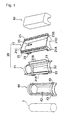
- the airbag assembly of the embodiment generally comprises the following members as shown in Fig. 1.
- the present invention has a feature in which the retainer 20 has an upper retainer 21 for housing the airbag 10 and a lower retainer 31 for holding the inflator I, wherein the upper retainer 21 is made of a resin such as nylon and polypropylene, and the lower retainer 31 is made of a metal such as a cold rolled sheet steel. Now the structure of the retainer 20 will be described.
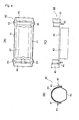
- the upper retainer 21 has a rectangular frame-like structure having sidewalls 21 A to 21D on the four sides thereof as shown in Figs. 2(A) to 2(D).
- the sidewalls 21A and 21B among the sidewalls 21A to 21D, extending along the longitudinal direction of the upper retainer 21, the sidewall 21 A extends upward further than the sidewall 21 B.
- Windows AW and BW are formed at the lower parts of the sidewalls 21A and 21B respectively.
- a plurality of ribs 25 are provided on the upper edges of the sidewalls 2 1 A and 2 1 B along the longitudinal direction of the upper retainer 21. The ribs 25 function as reinforcement against a load from an inflating bag.
- the sidewalls 21 C and 21 D which are orthogonal to the sidewalls 2 1 A and 2 1 B of the upper retainer 21, each have a semicircular recess 21R formed by cutting away the lower parts thereof as shown in Fig. 2(B).
- the ends of the inflator I are both fit into these recesses 21R.
- the upper retainer 21 has four flange-shaped fastening portions 23 each at the bottom corner thereof, which extrude inwardly. As shown in Fig. 2(E) for easy understanding, each fastening portion 23 has a bolt-hole 23b and a notch 23a formed at the free end and the fixed end thereof respectively. This notch 23a is intended to facilitate the fastening portion 23 to be deformed when a passenger hits his head against an instrument panel.
- These fastening portions 23 are each bolted, in a surface-to-surface contact state, with the corresponding fastening portions 33 (which will be described referring to Figs. 3(A) to 3(C) and 5(A) to 5(C)) of the lower retainer 31.
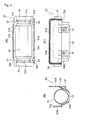
- the lower retainer 31 has a bottom portion 32 for accommodating the inflator I (see Fig. 1) as shown in Figs. 3(A) to 3(C).
- the bottom portion 32 is formed to have a half-hexagonal cross-section at the central part thereof and semicircular cross-sections at the both ends thereof (right and left ends of Figs. 3(A) and 3(C)).
- Semi-annular arch portions 35 are provided on the right and left ends of the bottom portion 32. The arch portions 35 are fit inside arch portions 45 of the bag plate 40.
- Sidewalls 31A and 31B stand up on upper edges 31x and 31y of the bottom portion 32 extending along the longitudinal direction of the bottom portion 32 respectively.
- the sidewall 31 A extends upward higher and laterally wider than the sidewall 31B.
- the sidewalls 31A and 31B are located inside the sidewalls 21A and 21B respectively, in a state such that the upper retainer 21 and the lower retainer 31 are assembled (see Fig. 5(A) to 5(C)).
- the sidewalls 31A and 31 B of the lower retainer 31 partly overlap the sidewalls 21A and 21B of the upper retainer 21 respectively (see the half-tone dot meshing part indicated in Fig. 3(C)).
- the overlapped part is an order of about 10 to 20 mm in width.
- the inside parts of the walls 31A and 31B surrounded by the overlapped portions are exposed outward at the windows AW and BW of the sidewalls 21A and 21B respectively.
- the bottom portion 32 has four flange-shaped fastening portions 33, each formed around the corner of the upper edge.
- the portions 33 correspond to the fastening portions 23 of the upper retainer 21, each having a bolt-hole 33a formed therein.
- At least one vehicle-mounting bracket 37 is attached to the side surfaces of the bottom portion 32 and the sidewall 31A.
- the vehicle-mounting bracket 37 is intended to attach the retainer 20 to an interior frame of a vehicle.
- the sidewall 31A exposed partly outward at the window AW of the sidewall 21A serves to provide a wide area for attaching a bracket thereon, thereby rendering a variety of shapes and sizes of vehicle-mounting brackets available.
- the bag plate 40 is intended to clamp the airbag 10 and the inflator I (see Fig. 1) inside the retainer 20.
- the bag plate 40 has two flanges 41 extending in parallel along the longitudinal direction. Between these flanges 41 of the bag plate 40, the bottom portion 42 with a half-hexagonal cross section is provided at the lower part of the central portion of the bag plate 40 extending along the longitudinal direction.
- the bottom portion 42 is arranged along the inner surface of the bottom portion 32 of the lower retainer 31. Between these flanges 41, semicircular arch portions 45 are provided on both longitudinal ends of the bag plate 40.
- the arch portions 45 are arranged along the arch portions 35 of the lower retainer 31.
- the flanges 41 Corresponding to the fastening portions 23 of the upper retainer 21 and the fastening portions 33 of the lower retainer 31, the flanges 41 have four fastening portions 43, each formed around the upper edge corner of the bag plate 40.
- the inflator I is of a cylindrical shape as shown in Fig. 1, and inserted between the bottom portion 42 and the arch portion 45.
- the retainer 20 with the above-described arrangement will be described in an assembled state.
- the retainer 20 has the lower retainer 31 arranged under the upper retainer 21 as shown in Fig. 5(A) to 5(C).
- the lower retainer 31 is assembled in the upper retainer 21 from the upper side of retainer 20.
- the sidewalls 31A and 31B of the lower retainer 31 are located inside the sidewalls 21A and 21B of the upper retainer 21 respectively.
- the fastening portions 33 of the lower retainer 31 each lie on the corresponding fastening portions 23 of the upper retainer 21 in a closely contacting manner.
- the inflator I see Fig.
- the retainer 20 is fixedly mounted in a vehicle body by fixing brackets 27 and the vehicle-mounting brackets 37.
- the retainer 20 is fixedly mounted in an instrument panel P of a vehicle as shown in Fig. 10(A).
- the retainer 20 is deformed in a manner such that the central portions of the sidewalls 31A and 31B of the lower retainer 31 are deformed outward upon receiving an expansive force of an inflating bag as shown in Fig. 6. This is called a fish-mouth deformation. Reinforcing these sidewalls 31A and 31B at the overlapped portions by the sidewalls 21A and 21B of the upper retainer 21 serves to prevent the fish-mouth deformation of the retainer 20.
- FIGs. 12(A) and 12(B) are enlarged schematic views of the vicinity of the fastening portion of the retainer, respectively, in a normal state and in a deformed state cause by an applied force.
- the upper surface of the fastening portion 23 of the upper retainer 21 and the lower surface around the corner of the lower retainer 31 are fastened with a bolt-and-nut 44 in a closely contacting manner.
- the fastening portion 23 of the upper retainer 21 is deformed, causing the corner of the upper retainer 21 to be dislocated downward along the sidewall 31A of the lower retainer 31.
- This deformation serves to absorb a load.
- the notch 23a is provided at the fastening portion 23 as shown in Fig. 2(E)
- a crack or breakage of the fastening portion 23 at the notch 23a facilitates the upper retainer 21 to be deformed.
- FIGs. 7(A) to 7(C) are diagrammatic views illustrating another example of assembling the retainer.
- the upper retainer 21 and the lower retainer 31 are fastened in a state such that a left fastening portion 33L of the lower retainer 31 underlies a left fastening portion 23L of the upper retainer 21, on the other hand, a right fastening portion 33R of the lower retainer 31 overlies a right fastening portion 23R of the upper retainer 21.
- the lower retainer 31 comes close to the upper retainer 21 from below, and the right fastening portion 33R of the lower retainer 31 is fixed onto the right fastening portion 23R of the upper retainer 21 as shown in Fig. 7(B). Then, the sidewall 31B of the lower retainer 31 is inserted inside the sidewall 21B of the upper retainer 21 as shown in Fig. 7(C).
- the retainer can be assembled so as to get the lower retainer 31 to come into the upper retainer 21 from below.
- the retainer can be easily assembled even if the lower retainer 31 has a protrusion H as shown in two-dot chain lines in Fig. 7(B).
- Figs. 8(A) to 8(C), and 8(E) are each diagrammatic side views of different examples of upper retainers of a retainer.
- Fig. 8(D) is a diagrammatic side view illustrating a state in which a plurality of upper retainers shown in Fig. 8(C) is stacked.
- An upper retainer 51 in Fig. 8(A) is of a standard type.
- An upper retainer 52 in Fig. 8(B) is of a wide-mouthed type having a wide-open mouth.
- the upper retainer 52 of this type has an advantage of a low profile, accordingly it is available for an airbag assembly of a vehicle that has limited layout space in an instrument panel in the depth direction.
- An upper retainer 53 in Fig. 8(c) is of a type having a trumpet-shaped mouth.
- the width L1 of an upper mouth is formed wider than the width L2 of a lower mouth.
- a plurality of upper retainers of the type, in which the width L1 of an upper mouth is larger than the width L2 of a lower mouth as shown in Fig. 8(C), can be stacked as shown in Fig. 8(D), thereby having an advantage of taking up less space for transportation or inventory.
- the upper retainer 53' can be formed so as to have stepped-sidewalls by providing steps 53a and 53b substantially at the midpoints in the vertical direction of the sidewalls thereof as shown in Fig. 8(E).
- a plurality of retainers of this type can be also stacked as is the case with that shown in Figs. 8(C) and 8(D), thereby having an advantage of taking up less space for transportation or inventory.
- Figs. 9(A) and 9(B) are diagrammatic side views illustrating another example of a retainer
- Fig. 9(C) is a diagrammatic schematic view of the example.
- the retainer in Figs. 9(A) to 9(C) has a cut-raise 31 ⁇ and a protrusion 31 ⁇ formed on a sidewall (a lower sidewall) 31X of a lower retainer.
- the cut-raise 31 ⁇ is formed close to a bottom 21Y of a sidewall (an upper sidewall) 21X of an upper retainer, and under an overlapped portion W of the upper sidewall 21X overlapping the lower sidewall 31X.
- the cut-raise 31 ⁇ can be provided by, e.g., punching a part of the lower sidewall 31X, and then bending and raising it.
- the protrusion 31 ⁇ is formed under the cut-raise 31 ⁇ so as to extend along the longitudinal direction of the lower sidewall 31X.
- the protrusion 31 ⁇ can be provided by, e.g., forming a crest in the lower retainer by press molding.
- a retainer provided with the cut-raise 31 ⁇ and the protrusion 31 ⁇ has the following advantage.
- the upper retainer When a passenger hits his head against an instrument panel P (see Figs. 10(A) to 10(C)), the upper retainer is pushed from the upper mouth thereof.
- the bottom 21 Y of the upper sidewall 21X hits and crushes the protrusion 31 ⁇ of the lower sidewall 31X, serving to absorb a load against the passenger.
- the upper retainer of the retainer is made of a resin such as nylon and polypropylene in the embodiment described above, the upper retainer may be made of a steel plate as shown in Figs. 11 (A) and 11(B).
- Figs. 11 (A) and 11(B) are a schematic view and a side view of an upper retainer of a retainer respectively, according to another embodiment of the present invention.
- an upper retainer 60 of a retainer shown in Figs. 11(A) and 11(B) is formed by deep drawing.
- a light metal containing at least one of magnesium and aluminum can be used instead of the steel plate as mentioned in this example.
- An airbag of the present invention can be used for all other types of vehicles other than automobiles, including bicycles, motorcycles, rockets, space-crafts, boats, ships, airplanes; play equipment such as roller coasters; mobile equipment for human beings including pedestrians and for animals such as dogs and cats; wheel chairs, and electric walking machines.
- the airbag may also be used for immovable bodies such as real estates.
- the present invention is intended to provide an airbag retainer having advantages of reduced cost and weight, and so on.
Abstract
Description
To solve the above-described problems, an airbag retainer of the present invention, for housing and holding an airbag which inflates in an emergency and an inflator which supplies gas for inflating the airbag, comprises a bag-housing member (an upper portion: an upper retainer) made of a resin, and an inflator-holding member (a lower portion: a lower retainer) made of a metal.
Compared to a solid resin retainer, because of the increased heat endurance strength of the inflator-holding member, an inflator in a wider range of types is available for the airbag retainer. In addition, the above increased strength permits the inflator-holding member to reduce its thickness, accordingly allowing the retainer to reduce its height.
When the airbag retainer of the present invention is applied to a plurality of different types of vehicles, the only thing to do is to choose a usable bracket, which is to be spot-welded to the lower retainer, according to a vehicle type. This renders the airbag retainer suitable for a wider range of uses. Welding the bracket to the lower retainer is a known fixing art as has been used for conventional retainers.
This structure serves to enhance the strength against an expansive force of an inflating bag, thereby to prevent a fish-mouth deformation of the retainer. The fish-mouth deformation means a state in which the central portions of the sidewalls of the lower retainer are deformed outward upon receiving the expansive force of an inflating bag.
Also, according to the airbag retainer of the present invention, the upper retainer and the lower retainer may have a plurality of fastening portions. At least one of the plurality of fastening portions is preferably broken or stretched when a load is applied to an instrument panel of an automobile.
The metal lower retainer bear a tension of an inflating bag on its flange surfaces, thereby serving to provide enough strength of the airbag retainer. When a passenger hits his head against an instrument panel, on the other hand, the resin upper retainer is easily deformed because of less constraint in the downward direction. With this arrangement, the lower retainer can be built to the upper retainer from either above or below.
The depressed portion is thinner than another portion of the same fastening portion. When a passenger hits his head against an instrument panel P, accordingly, the fastening portion is likely to be sheared or deformed at the depression.
For attaching a vehicle-mounting bracket (a bracket for mounting an airbag module on an internal frame of a vehicle body) to the side wall of the lower retainer, the window of the sidewall of the upper retainer serves to provide a wide area where the side wall of the lower retainer is exposed outward, thereby rendering a variety of vehicle-mounting brackets available.
When the material costs of resin and metal for the same area are compared, the resin costs about three times of the metal. According to this embodiment of the present invention, the window formed in the sidewall serves to reduce the quantity of resin used, leading to achieve the reduced cost.
With this construction, the plurality of reinforcement portions serves to suppress the deformation of the upper retainer caused by a load of an inflating bag.
With this configuration, a plurality of retainers can be stacked, thereby requiring less space for transportation or inventory.
The
The
The inflator I is of a cylindrical shape as shown in Fig. 1, and inserted between the
The
When a passenger hits his head against an instrument panel P (see Fig. 10(A) to 10(C)), the
Figs. 12(A) and 12(B) are enlarged schematic views of the vicinity of the fastening portion of the retainer, respectively, in a normal state and in a deformed state cause by an applied force.
In the normal state shown in Fig. 12(A), the upper surface of the
Figs. 7(A) to 7(C) are diagrammatic views illustrating another example of assembling the retainer.
In the case shown in Figs. 7(A) to 7(C), the
Figs. 8(A) to 8(C), and 8(E) are each diagrammatic side views of different examples of upper retainers of a retainer. Fig. 8(D) is a diagrammatic side view illustrating a state in which a plurality of upper retainers shown in Fig. 8(C) is stacked.
An
An
A plurality of upper retainers of the type, in which the width L1 of an upper mouth is larger than the width L2 of a lower mouth as shown in Fig. 8(C), can be stacked as shown in Fig. 8(D), thereby having an advantage of taking up less space for transportation or inventory.
The upper retainer 53' can be formed so as to have stepped-sidewalls by providing
The retainer in Figs. 9(A) to 9(C) has a cut-raise 31α and a protrusion 31β formed on a sidewall (a lower sidewall) 31X of a lower retainer. The cut-raise 31α is formed close to a bottom 21Y of a sidewall (an upper sidewall) 21X of an upper retainer, and under an overlapped portion W of the
Figs. 11 (A) and 11(B) are a schematic view and a side view of an upper retainer of a retainer respectively, according to another embodiment of the present invention.
By using a steel plate with thickness ranging from 0.8 to 1.2 mm, an
An airbag of the present invention can be used for all other types of vehicles other than automobiles, including bicycles, motorcycles, rockets, space-crafts, boats, ships, airplanes; play equipment such as roller coasters; mobile equipment for human beings including pedestrians and for animals such as dogs and cats; wheel chairs, and electric walking machines. The airbag may also be used for immovable bodies such as real estates.
Claims (8)
- An airbag retainer (20) for housing and holding an airbag (10) which inflates in an emergency and an inflator (I) which supplies gas for inflating the airbag (10), comprising:wherein a plurality of flange-shaped fastening portions (23; 33) of the upper retainer (21) and the lower retainer (31) is arranged to have surface-to-surface contact with each other, and at least one fastening portion (23) of the upper retainer (21) among the plurality of fastening portions underlies the corresponding fastening portion (33) of the lower retainer (31), characterized in that the upper retainer (21) is made of a light metal containing at least one of magnesium and aluminum and the lower retainer (31) is made of steel.an upper retainer (21) for housing the airbag (10); anda lower retainer (31) for holding the inflator (I),
- An airbag retainer (20) for housing and holding an airbag (10) which inflates in an emergency and an inflator (I) which supplies gas for inflating the airbag (10), comprising:wherein a plurality of flange-shaped fastening portions (23; 33) of the upper retainer (21) and the lower retainer (31) is arranged to have surface-to-surface contact with each other, and at least one fastening portion (23) of the upper retainer (21) among the plurality of fastening portions underlies the corresponding fastening portion (33) of the lower retainer (31),an upper retainer (21) for housing the airbag (10); anda lower retainer (31) for holding the inflator (I),
characterized in that the upper retainer (21) is made of a steel plate having a thickness in the range of 0.8 mm to 1.2 mm and the lower retainer (31) is made of a metal. - The airbag retainer (20) according to Claim 1 or 2, wherein the upper retainer (21) and the lower retainer (31) have a plurality of fastening portions (23; 33), and at least one of the plurality of fastening portions (23; 33) is broken or stretched when a load is applied to an instrument panel of an automobile.
- The airbag retainer (20) according to anyone of Claims 1-3, wherein the upper retainer (21) has a frame-shaped structure provided with sidewalls (21A-21D) on the four sides, and the lower retainer (31) has sidewalls (31A, 31B) on a pair of opposite sides among the four sides, such that the sidewalls (31A, 31B) of the lower retainer (31) partly overlap the corresponding sidewalls (21A, 21B) of the upper retainer (21).
- The airbag retainer according to Claim 4, wherein the sidewall (21A, 21B) of the upper retainer (21), which overlaps the corresponding sidewall (31A, 31B) of the lower retainer (31), has a window (AW, BW) formed by cutting away the lower part of the sidewall, and an outer surface of the sidewall (31A, 31B) of the lower retainer (31) is exposed outward at the window (AW, BW).
- The airbag retainer (20) according to anyone of Claims 1-5, wherein each of the plurality of fastening portions (23) of the upper retainer (21) has a depression (23a) formed thereon.
- The airbag retainer (20) according to anyone of Claims 1-6, wherein a plurality of reinforcement portions (25) is provided along edges of an upper mouth of the upper retainer (21).
- An airbag device comprising:wherein the retainer (20) is configured according to anyone of the claims 1-7.an airbag (10) to be inflated in an emergency,an inflator (I) which supplies gas for inflating the airbag (10), anda retainer (20) for housing the airbag (10) and holding the inflator (I),
Applications Claiming Priority (5)
| Application Number | Priority Date | Filing Date | Title |
|---|---|---|---|
| JP2000334394 | 2000-11-01 | ||
| JP2000334394 | 2000-11-01 | ||
| JP2001275410 | 2001-09-11 | ||
| JP2001275410A JP2002200955A (en) | 2000-11-01 | 2001-09-11 | Air bag retainer |
| EP01123281A EP1203703B1 (en) | 2000-11-01 | 2001-10-04 | Airbag retainer |
Related Parent Applications (2)
| Application Number | Title | Priority Date | Filing Date |
|---|---|---|---|
| EP01123281A Division EP1203703B1 (en) | 2000-11-01 | 2001-10-04 | Airbag retainer |
| EP01123281.6 Division | 2001-10-04 |
Publications (3)
| Publication Number | Publication Date |
|---|---|
| EP1577173A2 true EP1577173A2 (en) | 2005-09-21 |
| EP1577173A3 EP1577173A3 (en) | 2005-09-28 |
| EP1577173B1 EP1577173B1 (en) | 2007-03-14 |
Family
ID=26603268
Family Applications (2)
| Application Number | Title | Priority Date | Filing Date |
|---|---|---|---|
| EP05009588A Expired - Lifetime EP1577173B1 (en) | 2000-11-01 | 2001-10-04 | Airbag retainer |
| EP01123281A Expired - Lifetime EP1203703B1 (en) | 2000-11-01 | 2001-10-04 | Airbag retainer |
Family Applications After (1)
| Application Number | Title | Priority Date | Filing Date |
|---|---|---|---|
| EP01123281A Expired - Lifetime EP1203703B1 (en) | 2000-11-01 | 2001-10-04 | Airbag retainer |
Country Status (4)
| Country | Link |
|---|---|
| US (1) | US6709005B2 (en) |
| EP (2) | EP1577173B1 (en) |
| JP (1) | JP2002200955A (en) |
| DE (2) | DE60113212T2 (en) |
Families Citing this family (14)
| Publication number | Priority date | Publication date | Assignee | Title |
|---|---|---|---|---|
| US6565114B1 (en) * | 2001-11-06 | 2003-05-20 | General Motors Corporation | Plastic air bag module with variable cushion vent area adjustment |
| US7150467B2 (en) * | 2002-06-18 | 2006-12-19 | Delphi Technologies, Inc. | Housing for airbag module |
| US7097196B2 (en) * | 2002-11-27 | 2006-08-29 | Tk Holdings, Inc. | Modular airbag housing and method of manufacture |
| FI20040294A0 (en) * | 2004-02-25 | 2004-02-25 | Nokia Corp | Method for selecting transmission channel parameters, radio systems, controls, terminal and base station |
| US7374198B2 (en) * | 2004-04-02 | 2008-05-20 | Toyoda Gosei Co., Ltd | Airbag module canister |
| JP4407418B2 (en) | 2004-07-30 | 2010-02-03 | タカタ株式会社 | Air bag device and its case |
| DE102004040235A1 (en) * | 2004-08-13 | 2006-03-02 | Takata-Petri Ag | Passenger airbag module |
| JP4543824B2 (en) | 2004-08-25 | 2010-09-15 | タカタ株式会社 | Air bag device and its case |
| JP4601388B2 (en) * | 2004-10-20 | 2010-12-22 | カルソニックカンセイ株式会社 | Airbag attachment structure |
| DE102007046211A1 (en) * | 2007-09-27 | 2009-04-02 | GM Global Technology Operations, Inc., Detroit | Airbag module with surface structure |
| US20090152838A1 (en) * | 2007-12-17 | 2009-06-18 | Nissan Technical Center North America, Inc. | Airbag inflator device and method of installation |
| US20100181746A1 (en) * | 2009-01-16 | 2010-07-22 | Rose Larry D | Airbag module housing |
| US9789836B2 (en) * | 2015-09-01 | 2017-10-17 | GM Global Technology Operations LLC | Ring bracket for snap-lock engagement verification |
| US10604259B2 (en) | 2016-01-20 | 2020-03-31 | Amsafe, Inc. | Occupant restraint systems having extending restraints, and associated systems and methods |
Citations (4)
| Publication number | Priority date | Publication date | Assignee | Title |
|---|---|---|---|---|
| EP0739788A1 (en) * | 1995-04-26 | 1996-10-30 | Morton International, Inc. | Cover attachment for an air bag module |
| US5718447A (en) * | 1996-09-10 | 1998-02-17 | Morton International, Inc. | Pressure relief in airbag module reaction canisters |
| US5947510A (en) * | 1998-05-08 | 1999-09-07 | Breed Automotive Technology, Inc. | Air bag module |
| DE19909426A1 (en) * | 1998-11-13 | 2000-05-25 | Petri Ag | Air bag module, especially for side- or passenger protection comprises casing made from two parts held together by snap-in catches, simplifying construction and mounting |
Family Cites Families (8)
| Publication number | Priority date | Publication date | Assignee | Title |
|---|---|---|---|---|
| JP3118974B2 (en) * | 1992-08-31 | 2000-12-18 | タカタ株式会社 | Airbag device |
| JP3198861B2 (en) * | 1995-02-22 | 2001-08-13 | 豊田合成株式会社 | Airbag device |
| JPH09142242A (en) * | 1995-11-27 | 1997-06-03 | Toyoda Gosei Co Ltd | Air bag device for passenger's seat |
| US5678850A (en) * | 1996-08-09 | 1997-10-21 | Morton International, Inc. | Cover mounting arrangement for airbag module |
| JP2000118343A (en) * | 1998-10-13 | 2000-04-25 | Toyota Motor Corp | Instrument panel with integrated airbag door portion |
| DE29911540U1 (en) * | 1999-06-29 | 2000-09-07 | Petri Ag | Airbag module |
| JP4120132B2 (en) * | 1999-08-19 | 2008-07-16 | タカタ株式会社 | Air bag device and its case |
| JP2001253311A (en) * | 2000-03-09 | 2001-09-18 | Takata Corp | Air bag device for front passenger seat |
-
2001
- 2001-09-11 JP JP2001275410A patent/JP2002200955A/en not_active Withdrawn
- 2001-10-04 DE DE60113212T patent/DE60113212T2/en not_active Expired - Lifetime
- 2001-10-04 EP EP05009588A patent/EP1577173B1/en not_active Expired - Lifetime
- 2001-10-04 DE DE60127321T patent/DE60127321T2/en not_active Expired - Lifetime
- 2001-10-04 EP EP01123281A patent/EP1203703B1/en not_active Expired - Lifetime
- 2001-10-25 US US09/983,739 patent/US6709005B2/en not_active Expired - Lifetime
Patent Citations (4)
| Publication number | Priority date | Publication date | Assignee | Title |
|---|---|---|---|---|
| EP0739788A1 (en) * | 1995-04-26 | 1996-10-30 | Morton International, Inc. | Cover attachment for an air bag module |
| US5718447A (en) * | 1996-09-10 | 1998-02-17 | Morton International, Inc. | Pressure relief in airbag module reaction canisters |
| US5947510A (en) * | 1998-05-08 | 1999-09-07 | Breed Automotive Technology, Inc. | Air bag module |
| DE19909426A1 (en) * | 1998-11-13 | 2000-05-25 | Petri Ag | Air bag module, especially for side- or passenger protection comprises casing made from two parts held together by snap-in catches, simplifying construction and mounting |
Non-Patent Citations (1)
| Title |
|---|
| WILHELM W: "KUNSTSTOFF ERSETZT METALL BEI AIRBAG-GEHAEUSEN" ATZ AUTOMOBILTECHNISCHE ZEITSCHRIFT, FRANCKH'SCHE VERLAGSHANDLUNG. STUTTGART, DE, vol. 100, no. 3, 1 March 1998 (1998-03-01), pages 210-214, XP000750972 ISSN: 0001-2785 * |
Also Published As
| Publication number | Publication date |
|---|---|
| JP2002200955A (en) | 2002-07-16 |
| DE60127321T2 (en) | 2008-01-10 |
| EP1577173B1 (en) | 2007-03-14 |
| EP1203703A2 (en) | 2002-05-08 |
| DE60127321D1 (en) | 2007-04-26 |
| US20020050701A1 (en) | 2002-05-02 |
| DE60113212T2 (en) | 2006-06-29 |
| EP1577173A3 (en) | 2005-09-28 |
| DE60113212D1 (en) | 2005-10-13 |
| EP1203703A3 (en) | 2004-01-02 |
| EP1203703B1 (en) | 2005-09-07 |
| US6709005B2 (en) | 2004-03-23 |
Similar Documents
| Publication | Publication Date | Title |
|---|---|---|
| US6406056B2 (en) | Air bag device for passenger's seat | |
| EP1577173B1 (en) | Airbag retainer | |
| US6536802B1 (en) | Vehicle instrument panel assembly | |
| US10978760B2 (en) | Structural component, battery housing, and motor vehicle with such a battery housing | |
| US5582424A (en) | Occupant restraint device | |
| JPH05139237A (en) | Mounting structure of airbag module for assistant's seat | |
| KR100503294B1 (en) | Passenger airbag module for a motor vehicle | |
| EP0965497A1 (en) | Side impact airbag device for restraining occupant's head | |
| US20050218630A1 (en) | Airbag module canister | |
| US5775730A (en) | Airbag module diffuser | |
| US6966575B2 (en) | Air bag system mounting structure | |
| JP4880470B2 (en) | Housing for housing automobile airbag module | |
| JP5346752B2 (en) | Method for manufacturing case body of airbag device, case body of airbag device, and airbag device | |
| EP3708422B1 (en) | Side air bag device and method for manufacturing same | |
| JP3701590B2 (en) | Case reinforcement structure for automobile airbag device | |
| JPH1148895A (en) | Air bag device | |
| CN211223355U (en) | Airbag housing and airbag device | |
| JP3087803B2 (en) | Airbag cover | |
| KR100397513B1 (en) | connecting device of air bag modul for automobiles | |
| JP2607257Y2 (en) | Airbag device | |
| JP2598248Y2 (en) | Airbag module cover | |
| JPH0613963U (en) | Vehicle airbag case | |
| KR100291458B1 (en) | A cover fixture and manufacture method of airbag | |
| JP2530760Y2 (en) | Car knee bolster | |
| JPH05270340A (en) | Air bag structure |
Legal Events
| Date | Code | Title | Description |
|---|---|---|---|
| PUAI | Public reference made under article 153(3) epc to a published international application that has entered the european phase |
Free format text: ORIGINAL CODE: 0009012 |
|
| PUAL | Search report despatched |
Free format text: ORIGINAL CODE: 0009013 |
|
| AC | Divisional application: reference to earlier application |
Ref document number: 1203703 Country of ref document: EP Kind code of ref document: P |
|
| AK | Designated contracting states |
Kind code of ref document: A2 Designated state(s): DE FR GB SE |
|
| AK | Designated contracting states |
Kind code of ref document: A3 Designated state(s): DE FR GB SE |
|
| 17P | Request for examination filed |
Effective date: 20060208 |
|
| AKX | Designation fees paid |
Designated state(s): DE FR GB SE |
|
| GRAP | Despatch of communication of intention to grant a patent |
Free format text: ORIGINAL CODE: EPIDOSNIGR1 |
|
| GRAS | Grant fee paid |
Free format text: ORIGINAL CODE: EPIDOSNIGR3 |
|
| GRAA | (expected) grant |
Free format text: ORIGINAL CODE: 0009210 |
|
| RIN1 | Information on inventor provided before grant (corrected) |
Inventor name: AMAMORI, ICHIRO |
|
| AC | Divisional application: reference to earlier application |
Ref document number: 1203703 Country of ref document: EP Kind code of ref document: P |
|
| AK | Designated contracting states |
Kind code of ref document: B1 Designated state(s): DE FR GB SE |
|
| REG | Reference to a national code |
Ref country code: GB Ref legal event code: FG4D |
|
| REF | Corresponds to: |
Ref document number: 60127321 Country of ref document: DE Date of ref document: 20070426 Kind code of ref document: P |
|
| REG | Reference to a national code |
Ref country code: SE Ref legal event code: TRGR |
|
| ET | Fr: translation filed | ||
| PLBE | No opposition filed within time limit |
Free format text: ORIGINAL CODE: 0009261 |
|
| STAA | Information on the status of an ep patent application or granted ep patent |
Free format text: STATUS: NO OPPOSITION FILED WITHIN TIME LIMIT |
|
| 26N | No opposition filed |
Effective date: 20071217 |
|
| PGFP | Annual fee paid to national office [announced via postgrant information from national office to epo] |
Ref country code: SE Payment date: 20071004 Year of fee payment: 7 |
|
| PGFP | Annual fee paid to national office [announced via postgrant information from national office to epo] |
Ref country code: FR Payment date: 20071009 Year of fee payment: 7 |
|
| EUG | Se: european patent has lapsed | ||
| REG | Reference to a national code |
Ref country code: FR Ref legal event code: ST Effective date: 20090630 |
|
| PG25 | Lapsed in a contracting state [announced via postgrant information from national office to epo] |
Ref country code: FR Free format text: LAPSE BECAUSE OF NON-PAYMENT OF DUE FEES Effective date: 20081031 |
|
| PG25 | Lapsed in a contracting state [announced via postgrant information from national office to epo] |
Ref country code: SE Free format text: LAPSE BECAUSE OF NON-PAYMENT OF DUE FEES Effective date: 20081005 |
|
| PGFP | Annual fee paid to national office [announced via postgrant information from national office to epo] |
Ref country code: GB Payment date: 20121003 Year of fee payment: 12 |
|
| GBPC | Gb: european patent ceased through non-payment of renewal fee |
Effective date: 20131004 |
|
| PG25 | Lapsed in a contracting state [announced via postgrant information from national office to epo] |
Ref country code: GB Free format text: LAPSE BECAUSE OF NON-PAYMENT OF DUE FEES Effective date: 20131004 |
|
| PGFP | Annual fee paid to national office [announced via postgrant information from national office to epo] |
Ref country code: DE Payment date: 20171019 Year of fee payment: 17 |
|
| REG | Reference to a national code |
Ref country code: DE Ref legal event code: R082 Ref document number: 60127321 Country of ref document: DE Representative=s name: KRAUS & WEISERT PATENTANWAELTE PARTGMBB, DE Ref country code: DE Ref legal event code: R081 Ref document number: 60127321 Country of ref document: DE Owner name: JOYSON SAFETY SYSTEMS JAPAN K.K., JP Free format text: FORMER OWNER: TAKATA CORP., TOKIO/TOKYO, JP |
|
| REG | Reference to a national code |
Ref country code: DE Ref legal event code: R119 Ref document number: 60127321 Country of ref document: DE |
|
| PG25 | Lapsed in a contracting state [announced via postgrant information from national office to epo] |
Ref country code: DE Free format text: LAPSE BECAUSE OF NON-PAYMENT OF DUE FEES Effective date: 20190501 |