EP1577107B1 - A device for accurate positioning of an object on a frame - Google Patents
A device for accurate positioning of an object on a frame Download PDFInfo
- Publication number
- EP1577107B1 EP1577107B1 EP05101690A EP05101690A EP1577107B1 EP 1577107 B1 EP1577107 B1 EP 1577107B1 EP 05101690 A EP05101690 A EP 05101690A EP 05101690 A EP05101690 A EP 05101690A EP 1577107 B1 EP1577107 B1 EP 1577107B1
- Authority
- EP
- European Patent Office
- Prior art keywords
- printhead
- spherical segment
- frame
- carriage
- leaf spring
- Prior art date
- Legal status (The legal status is an assumption and is not a legal conclusion. Google has not performed a legal analysis and makes no representation as to the accuracy of the status listed.)
- Not-in-force
Links
Images


Classifications
-
- B—PERFORMING OPERATIONS; TRANSPORTING
- B41—PRINTING; LINING MACHINES; TYPEWRITERS; STAMPS
- B41J—TYPEWRITERS; SELECTIVE PRINTING MECHANISMS, i.e. MECHANISMS PRINTING OTHERWISE THAN FROM A FORME; CORRECTION OF TYPOGRAPHICAL ERRORS
- B41J25/00—Actions or mechanisms not otherwise provided for
- B41J25/34—Bodily-changeable print heads or carriages
-
- B—PERFORMING OPERATIONS; TRANSPORTING
- B41—PRINTING; LINING MACHINES; TYPEWRITERS; STAMPS
- B41J—TYPEWRITERS; SELECTIVE PRINTING MECHANISMS, i.e. MECHANISMS PRINTING OTHERWISE THAN FROM A FORME; CORRECTION OF TYPOGRAPHICAL ERRORS
- B41J2/00—Typewriters or selective printing mechanisms characterised by the printing or marking process for which they are designed
- B41J2/005—Typewriters or selective printing mechanisms characterised by the printing or marking process for which they are designed characterised by bringing liquid or particles selectively into contact with a printing material
- B41J2/01—Ink jet
- B41J2/17—Ink jet characterised by ink handling
- B41J2/175—Ink supply systems ; Circuit parts therefor
- B41J2/17503—Ink cartridges
- B41J2/1752—Mounting within the printer
-
- B—PERFORMING OPERATIONS; TRANSPORTING
- B41—PRINTING; LINING MACHINES; TYPEWRITERS; STAMPS
- B41J—TYPEWRITERS; SELECTIVE PRINTING MECHANISMS, i.e. MECHANISMS PRINTING OTHERWISE THAN FROM A FORME; CORRECTION OF TYPOGRAPHICAL ERRORS
- B41J2202/00—Embodiments of or processes related to ink-jet or thermal heads
- B41J2202/01—Embodiments of or processes related to ink-jet heads
- B41J2202/20—Modules
Abstract
Description
- The invention relatas to a carriage for a printing system, comprising a printhead (4, 40) comprising a first spherical segment (8) at a first side and a second spherical segment (9) at a second side extending opposite the first side: a carriage frame (2) provided with a slot (3) for receiving the printhead (4, 40), comprising a recess (6) at the circumference of the slot (3) for receiving the second spherical segment (9); the carriage frame (2) further comprises positioning means (5, 17) for urging the printhead (4, 40) into a predetermined position.
- A device of this kind is known from the American patent
US-A-5 646 658 in which the outer surfaces of an ink cartridge are pressed against a specific surface of a frame, the Ink cartridge being pressed on the frame in directions perpendicular to the frame and in the direction of the length of the cartridge by means of springs situated on opposite surfaces of the frame. The cartridge can be aligned by means of spacers and setscrews extending in directions parallel to the frame and perpendicularly to the direction of the length of the cartridge. - The disadvantage of this device is that a plurality of actions have to be carried out by an end user, and only after the cartridge has been located between a first spring and the frame can a second spring be placed on the frame positioned on the opposite side of the first spring. After the second spring has been applied, at least three screws have to be tightened to align the cartridge in the Y-direction.
- The object of the invention is to provide a carriage which obviates the disadvantages of the prior art.
- To this end, a carriage according to claim 1 and 7 has been invented wherein the printhead comprises a first spherical segment at a first side and a second spherical segment at a second side situated opposite the first side, and the frame, which comprises a curved leaf spring which, after placing the printhead, exerts a force with a component in the radial and tangential direction on the printhead at the first spherical segment, the tangential component reaching a minimum in the situation In which the printhead is situated in the predetermined position, and a recess in which the second spherical segment can be pressed by positioning means comprising the curved leaf spring.
- By means of this Invention an interchangeable printhead can initially be mounted inaccurately in a frame provided with positioning means. After the printhead has been placed, the positioning means can exert a force on the printhead in such manner that the printhead Is moved accurately to the predetermined position. At this position the force in the direction of movement will reach Its minimum and the positioning means will hold the printhead accurately in that position.
- It will be clear that according to this principle the positioning means can also be mounted on the printhead for positioning. This can be applied in an alternative embodiment wherein the frame comprises a first spherical segment on a first side and a second spherical segment on a second side situated opposite the first side and the printhead which comprises a positioning means which after placing the printhead exerts a force with a component in the radial and tangential direction on the printhead at the first spherical segment, the tangential component reaching a minimum in the situation in which the printhead is situated In the predetermined position, and a recess in which the second spherical segment can be pressed by the positioning means.
- In another embodiment, the frame is provided with auxiliary means to prevent movement of the printhead in the direction of the height (2-direction). In this way after positioning, the printhead cannot work loose from the frame in dynamic surroundings and mechanical stability is achieved.
- Another embodiment of this invention comprises a symmetrically shaped curved leaf spring which encloses more than half of an arc of a circle. By selecting a symmetrical leaf spring the directing force will always be the direction of predetermined equilibrium of said spring. By this selection of a curved leaf spring enclosing more than half of an arc of a circle a correcting movement to the predetermined position can be achieved in the event of skewing after introduction of the printhead.
- In one embodiment of the present invention, the positioning means forms a unit with the frame and is formed by machining from the same work piece. This has advantages in the production of the whole carriage. By making the whole carriage from the same basic material, the whole frame including the positioning means can be made in one operation. This also has a positive influence on the elastic loadability of the connection between the positioning means and the frame.
- One advantage of an application of a carriage according to the invention as described hereinbefore is a printer provided with a carriage for positioning a printhead in an opening in the carriage frame in a predetermined position with respect to a plane extending in the direction of the plane of the carriage (plane X-Y), wherein the printhead comprises a first spherical segment at a first side and a second spherical segment at a second side situated opposite the first side, and the carriage frame, which comprises at least one positioning means which, after placing the printhead, exerts a force with a component in the radial and tangential direction on the printhead at the first spherical segment, the tangential component reaching a minimum in the situation in which the printhead is situated in the predetermined position, and a recess in which the second spherical segment can be pressed by the positioning means.
- The principle of the invention can advantageously be applied in this construction since accuracy in the positioning of a printhead finds direct expression in the quality of a print on a substrate. The location of a printhead in practice frequently does not take place in an accurately controlled environment in which very high location accuracies can be obtained, but is frequently carried out by end users. By means of the Invention, the positioning accuracies required for high print quality can nevertheless be obtained by means of the invention via this uncontrolled placing of the interchangeable printhead on a carriage Hereinafter it will be clear that where the term object is used, a printhead is meant.
- The invention will now be explained in detail with reference to examples illustrated in the following drawings.
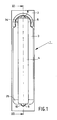
- Fig. 1
- is a top plan view of a device according to the invention.
- Fig. 2
- Is a truncated enlargement of the device of
Fig. 1 in a top plan view. - Fig. 3
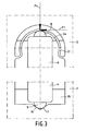
- is a truncated enlargement of another embodiment according to the invention in a top plan view.
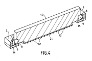
- Fig. 4
- is a perspective view of a cross-section on the line III-III of the device in
Fig. 1 - Fig. 5
- shows some examples of spherical segments in cross-section on the line III-III of the device in
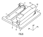
Fig. 1 . - Fig. 6
- is a perspective view of a set of devices as shown in
Fig. 4 . - Fig. 7
- is a side elevation of the device shown in
Fig. 4 with the addition of means for vertical positioning of the printhead. -
Figs. 1 ,2 and3 are top plan views of a carriage 1 according to the invention, in which anobject 4 is accurately positioned on abase frame 2. The device 1 comprises aslot 3 in which theprinthead 4 can be placed. The carriage 1 comprises parts which cause theprinthead 4 to be accurately positioned in theslot 3 with respect to thebase frame 2 relatively to all six of the degrees of freedom of theobject 4, namely three translatory movements (in the X, Y and Z directions) and three rotational movements (about the three aforesaid axes in the X, Y and Z directions, which are perpendicular to one another). The device 1 is provided with parts for releasably connecting theprinthead 4 to the saidbase frame 2. In order to meet the requirements of reproducibility and accuracy, each degree of freedom is precisely fixed once in the construction. - For this purpose, the
base frame 2 is provided, at the top of theslot 3, with a symmetrically shapedleaf spring 5. This leaf spring is symmetrical in the plane extending perpendicularly out of the drawing plane and through the line III-III. Thisleaf spring 5 can, for example, be made by the use of spark erosion. After spark erosion of the basic shape of theslot 3 from a metal base plate, the spaces around theleaf spring 5, in the same plate of base material, are eroded by spark erosion. In this process, surrounding material can be removed with high precision, leaving a very accurate symmetrically shapedleaf spring 5. -
Figs. 1 and2 show an embodiment in which theleaf spring 5 is constructed to be arcuate, and inFig. 3 straight elements are added to theleaf spring 17. - As shown in
Figs. 1 ,2 and3 , theprinthead 4 is provided withspherical segments printhead 4, but they can also be made by making the object side spherical, cylindrical or barrel-shaped for example. Some examples of this are shown inFigs. 5a - d , in which respectively aball 81, a horizontal locatingpin 82, a barrel-shaped object 83, and a vertical locatingpin 84 are pressed in. - The V-
groove 6 is in contact with theobject 4 via the bottomspherical segment 9 with twocontact points Figs. 1 ,2 and3 . These contact points will deform under load to give a contact surface. The extent of the deformation depends on the material and constructional properties of the embodiment. Hereinafter, these locations will be referred to as contact points. By introducing theprinthead 4 into theslot 3,spherical segment 8 of theobject 4 will be positioned against theleaf spring 5, the latter being deformed so that a force is exerted by theleaf spring 5 on theprinthead 4 with directional components in both the radial and the tangential direction of the arcuate segment of theleaf spring 5. The radial component of the spring force, indicated by Fr inFigs. 2 and3 , is provided by the radial deflection of theleaf spring 5 by thespherical segment 8 at the point contact with theleaf spring 5 and is proportional to the stiffness of theleaf spring 5. This radial spring force will pressspherical segment 9 into the V-groove 6, where contact with thebase frame 2 is formed by two point contacts. The tangential component, indicated by Ft inFigs. 2 and3 , arises from the configuration of theleaf spring 5. As a result of the symmetrical construction of theleaf spring 5 and the choice of an arcuate segment enclosing more than 180° of an arc of a circle, a directing force is delivered which presses the centre line of theprinthead 4 precisely in the plane through the line III-III and hence aligns it with respect to thebase frame 2. If theprinthead 4 is not placed correctly in alignment, a force component in the tangential direction opposed to the direction of the alignment error will be produced. Theleaf spring 5 will rotate theobject 4 about thespherical segment 9 in the V-groove 6 until the tangential force component has vanished. This will occur when theobject 4 is aligned in the direction of the length on the line through the axis of symmetry of the V-groove 6 and the axis of symmetry of theleaf spring 5, which is indicated by the line III-III inFig. 1 . Theobject 4 is accurately positioned by these components in the plane of thebase frame 2 in translation and rotation, free of the six degrees of freedom being clearly fixed. -
Fig. 4 is a perspective view of the cross-section on the line III-III of the device shown inFig. 1 . Aprinthead 40 of this kind contains a quantity of ink and is used inter alia in inkjet printers. At the bottom theprinthead 4 is provided with anozzle plate 41 containing a plurality ofnozzles 42. By energising theprinthead 40 imagewise, drops of ink are ejected in the direction of a sheet of receiving material moved along the nozzles (not shown), so that an image is formed on the receiving material. With regard to the quality of this image, it is important that thenozzle plate 41 should extend parallel with very high precision to the receiving material. This is achieved by positioning theprinthead 40 with high accuracy with respect to the plane of thebase frame 2. This accuracy must also be obtained with repeated use of such aprinthead 40. With the principle described above for accurate positioning of an object on a frame, the reproducibility is guaranteed. To obtain the above-described positioning on thebase frame 2, theprinthead 40 is provided with pressed-inballs - During operation of the carriage for transferring an image on to receiving material by means of a
printhead 40, considerable temperature differences occur. Depending on the phase of the process, theprinthead 40 will heat up very quickly or cool down very quickly. Different materials will expand or contract differently due to differences in coefficients of expansion, with the same heating and cooling. In order to keep the positioned printhead correctly positioned under these conditions, the device 1 can be provided with components which minimise the temperature transfer. For example, the carriage 1 can be provided with thermal insulating material, for example ceramic spherical segments and contact surfaces, at the contact points between theprinthead 40 and thebase frame 2, or by applying a thermally insulating coating to the said elements. - Apart from components for minimising the temperature differences within the device 1, the device 1 is also provided with components to control the differences in thermal expansion present. By fixing the expansion movement in all directions (X, Y and Z) on one side and offer stiffness on the opposite side, the positioning of the
printhead 40 is retained despite differences in thermal expansion. For example, in the X-direction, the expansion of theprinthead 40 is fixed by V-groove 6, while theleaf spring 5 offers stiffness and expansion possibilities. - In another embodiment (not shown), the base frame is provided with a spherical segment of the V-groove in the above-described embodiment, while the spherical segment of the printhead is replaced by a V-groove, so that the printhead is connected to the base frame via two contact points. On the opposite side, the base frame is provided with a spherical segment, while the printhead is constructed with a leaf spring, between which there is point contact.
-
Fig. 6 shows a combination of devices according to the invention as found typically in inkjet applications.Various printheads 40 are positioned in a plurality ofslots 3. - In the above embodiments, only three of the six degrees of freedom are fixed, namely two translatory movements in the plane of the
base frame 2 in the X and Y directions, and a rotational movement about the Z-axis perpendicular thereto. To be able to fix these degrees of freedom, the device 1 is provided, at the underside, withcontact surfaces Figs. 1 ,2 and3 . The way in which the degrees of freedom of the object are fixed depends on the geometry of the printhead.Fig. 7 illustrates one possibility of fixing these latter degrees of freedom of theprinthead 40. In order to obtain correct positioning in the Z-direction, perpendicular to the plane of thebase frame 2, and in rotational directions around two axes perpendicular to one another in the plane of thebase frame 2, in the X and Y directions, theprinthead 40 is provided, on theunderside 31, with two smooth contact surfaces 32 and 33. These contact surfaces 32 and 33 are positioned oncontact surfaces base frame 2 and extending parallel to the plane of thebase frame 2. By turning twoscrews subframes base frame 2 theprinthead 40 is pressed, at contact surfaces 50 and 51, by thescrews surfaces base frame 2 FZ. By applying this force FZ, a translatory movement is fixed in the vertical direction and two rotational movements about axes in the plane of the base frame. It is preferable for the force which fixes the vertical direction to be a pure force in the Z-direction. Any construction which imparts such a force FZ to theprinthead 4 can be used here. In this embodiment, use is made of screws which at the contact side are provided with freely rotating spherical segments (not shown). As a result, no tangential force component is transmitted during the turning of the screws on the object at contact points 50 and 51 between thescrews printhead 40, and the force applied is directed in the pure Z-direction. - One example of application of a carriage according to the invention as described above is a printer provided with a carriage for positioning a printhead in a slot of the carriage frame in a predetermined position with respect to a plane extending in the direction of the plane of the carriage (plane X-Y), the printhead comprising a first spherical segment at a first side and a second spherical segment at a second side extending opposite the first side, and the carriage frame, which comprises at least one positioning means, comprising a curved leaf spring which after placing the printhead exerts a force with a component in the radial and tangential direction on the printhead at the first spherical segment, the curved leaf spring being devised such that the tangential component reaches a minimum when the printhead is situated in the predetermined position and a recess in which the second spherical segment can be pressed by the positioning means. In another embodiment of the invention, in the printer described above, an auxiliary means is provided in the carriage frame and prevents movements of the printhead in the direction perpendicularly out of the plane of the frame (Z-direction). In a printer according to the invention, the curved leaf spring may comprise a symmetrically shaped curved leaf spring enclosing more than half of an arc of a circle. The curved leaf spring can be formed from the carriage frame material in a printer according to the invention.
- The recess in the above-described embodiments of the printer according to the invention may be conical or formed as a V-groove.
- Another example of an application of the carriage according to the invention as described hereinbefore is a printer provided with the carriage for positioning a printhead in a slot of the carriage frame in a predetermined position with respect to a plane extending in the direction of the plane of the carriage (plane X-Y), the carriage frame having at the first side a first spherical segment and, at a second side opposite the first side, a second spherical segment, and the printhead which comprises a positioning means comprising a curved leaf spring, which after placing the printhead, exerts a force with a component in the radial and tangential direction on the printhead at the first spherical segment, the curved leaf spring being devised such that the tangential component reaches a minimum when the printhead is situated in the predetermined position, and a recess in which the second spherical segment can be pressed by the positioning means. In a further embodiment of the invention, an auxiliary means is mounted in the carriage frame in the above-described printer and prevents movements of the printhead in the direction perpendicularly out of the plane of the frame (Z-direction).
- The resilient element in a printer according to the invention may comprise a symmetrically shaped curved leaf spring enclosing more than half of an arc of a circle. The curved leaf spring in a printer according to the invention can be formed from the carriage frame material.
- The recess in the above-described embodiments of the printer according to the invention may be conical or formed as a V-groove.
Claims (11)
- Carriage for a printing system, comprising- a printhead (4, 40) comprising a first spherical segment (8) at a first side and a second spherical segment (9) at a second side extending opposite the first side;- a carriage frame (2) provided with a slot (3) for receiving the printhead (4, 40), comprising a recess (6) at the circumference of the slot (3) for receiving the second spherical segment (9);- the carriage frame (2) further comprises positioning means (5, 17) for urging the printhead (4, 40) into a predetermined position,characterised in that, the positioning means (5, 17) comprises a curved leaf spring suitable for receiving the first spherical segment (8), and having a form such that, after receiving the first spherical segment (8), the curved leaf spring exerts a force on the first spherical segment having a component in the radial and tangential direction, wherein the tangential component reaches a minimum when the printhead is positioned at the predetermined position.
- A carriage according to claim 1, wherein the frame (2) comprises auxiliary means (36, 37), characterised in that the auxiliary means (36, 37) prevent movements of the printhead (4, 40) in the direction perpendicularly out of the plane of the frame (2) (Z-direction).
- A carriage according to claim 1, characterised in that the curved leaf spring is symmetrically shaped and encloses more than half of an arc of a circle.
- A carriage according to any one of the preceding claims, characterised in that the positioning means (5, 17) forms a unit with the frame (2) and is formed by machining from the work piece.
- A carriage according to any one of the preceding claims, characterised in that the recess (6) is formed as a V-groove.
- A carriage according to any one of claims 1 to 4, characterised in that the recess (6) is conical.
- Carriage for a printing system, comprising- a carriage frame provided with a slot for receiving a printhead,- the carriage frame comprising a first spherical segment at a first side at the circumference of the slot and a second spherical segment at a second side extending opposite the first side;- the printhead, comprising a recess at a first side for receiving the second spherical segment and positioning means at a second side extending opposite the first side for urging the printhead into a predetermined position,characterised in that, the positioning means comprises a curved leaf spring suitable for receiving the first spherical segment, and having a form such that, after receiving the first spherical segment, the curved leaf spring exerts a force on the first spherical segment having a component in the radial and tangential direction, wherein the tangential component reaches a minimum when the printhead is positioned at the predetermined position.
- A carriage according to claim 7, wherein the frame comprises auxiliary means, characterised in that the auxiliary means prevent movements of the printhead in the direction perpendicularly out of the plane of the frame (Z-direction).
- A carriage according to any one of claims 7 to 8, characterised in that the curved leaf spring is symmetrically shaped and encloses more than half of an arc of a circle.
- A carriage according to any one of claims 7 to 9, characterised in that the recess is formed as a V-groove.
- A carriage according to any one of claims 7 to 9, characterised in that the recess is conical.
Applications Claiming Priority (2)
| Application Number | Priority Date | Filing Date | Title |
|---|---|---|---|
| NL1025754A NL1025754C2 (en) | 2004-03-18 | 2004-03-18 | Device for accurately positioning an object on a frame. |
| NL1025754 | 2004-03-18 |
Publications (2)
| Publication Number | Publication Date |
|---|---|
| EP1577107A1 EP1577107A1 (en) | 2005-09-21 |
| EP1577107B1 true EP1577107B1 (en) | 2009-08-12 |
Family
ID=34836863
Family Applications (1)
| Application Number | Title | Priority Date | Filing Date |
|---|---|---|---|
| EP05101690A Not-in-force EP1577107B1 (en) | 2004-03-18 | 2005-03-04 | A device for accurate positioning of an object on a frame |
Country Status (7)
| Country | Link |
|---|---|
| US (1) | US7578588B2 (en) |
| EP (1) | EP1577107B1 (en) |
| JP (1) | JP4620507B2 (en) |
| CN (1) | CN1669800A (en) |
| AT (1) | ATE439243T1 (en) |
| DE (1) | DE602005015905D1 (en) |
| NL (1) | NL1025754C2 (en) |
Families Citing this family (6)
| Publication number | Priority date | Publication date | Assignee | Title |
|---|---|---|---|---|
| JP5250969B2 (en) | 2006-12-08 | 2013-07-31 | 富士ゼロックス株式会社 | Image forming apparatus, exposure apparatus, and image carrier unit |
| US8807716B2 (en) * | 2008-06-30 | 2014-08-19 | Fujifilm Dimatix, Inc. | Ink delivery |
| JP6150449B2 (en) * | 2015-03-11 | 2017-06-21 | 富士フイルム株式会社 | Inkjet recording device |
| US11014386B2 (en) * | 2016-04-11 | 2021-05-25 | Universal Display Corporation | Actuation mechanism for accurately controlling distance in OVJP printing |
| US10343411B2 (en) * | 2017-05-19 | 2019-07-09 | Sii Printek Inc. | Liquid ejecting head and liquid ejecting recording apparatus |
| CN110561913B (en) * | 2018-06-05 | 2021-05-18 | 松下知识产权经营株式会社 | Line head unit |
Family Cites Families (26)
| Publication number | Priority date | Publication date | Assignee | Title |
|---|---|---|---|---|
| US2255339A (en) * | 1940-07-22 | 1941-09-09 | Acme Newspictures Inc | Clamp for telephoto receivers |
| US2419316A (en) * | 1944-06-02 | 1947-04-22 | Herbert H Engemann | Anticrashing device for automatic push rods |
| US2830833A (en) * | 1953-07-17 | 1958-04-15 | Thompson Prod Inc | Joint assembly |
| US2797930A (en) * | 1954-07-13 | 1957-07-02 | Thompson Prod Inc | Stamped metal ball joint wheel suspension |
| US3059950A (en) * | 1955-04-11 | 1962-10-23 | Thompson Ramo Wooldridge Inc | Ball joint socket assemblies for steering linkage and the like |
| US4083545A (en) * | 1976-08-31 | 1978-04-11 | Trw Inc. | Spring shackle assembly |
| JPS5851514Y2 (en) * | 1979-01-10 | 1983-11-24 | 松下電工株式会社 | Variable direction mounting device |
| US4308543A (en) * | 1980-08-18 | 1981-12-29 | Burroughs Corporation | Rotating ink jet printing apparatus |
| JPS58182474U (en) * | 1982-05-31 | 1983-12-05 | 赤井電機株式会社 | sliding device |
| DE3445405A1 (en) * | 1984-12-13 | 1986-06-19 | Robert Bosch Gmbh, 7000 Stuttgart | ELECTROMAGNETICALLY ACTUABLE VALVE |
| US4901095A (en) * | 1988-11-10 | 1990-02-13 | Markem Corporation | Ink jet printing apparatus with adjustable print head |
| JP2775632B2 (en) * | 1988-11-28 | 1998-07-16 | オリンパス光学工業株式会社 | How to hold the recording head |
| US4875153A (en) * | 1988-12-05 | 1989-10-17 | Eastman Kodak Company | Mechanism for accurately mounting an electronic light emitting printhead assembly |
| US5245364A (en) * | 1988-12-30 | 1993-09-14 | Canon Kabushiki Kaisha | Image recording apparatus |
| JPH03136885A (en) * | 1989-10-20 | 1991-06-11 | Fuji Photo Film Co Ltd | Thermal head supporting mechanism in thermal printer apparatus |
| SU1763271A1 (en) * | 1990-10-08 | 1992-09-23 | Грузинский технический университет | Spring suspension of rail vehicle |
| DE4309255A1 (en) * | 1993-03-16 | 1994-09-22 | Francotyp Postalia Gmbh | Modular inkjet print head |
| US5548311A (en) * | 1994-02-28 | 1996-08-20 | Spectra, Inc. | Mount for replaceable ink jet head |
| JP2770141B2 (en) * | 1994-11-08 | 1998-06-25 | セイコーインスツルメンツ株式会社 | Printer |
| US6387184B1 (en) * | 1998-01-09 | 2002-05-14 | Fastar, Ltd. | System and method for interchangeably interfacing wet components with a coating apparatus |
| KR100297784B1 (en) * | 1998-03-20 | 2001-09-06 | 윤종용 | Device for controlling slant of laser scanner in printer |
| US6145980A (en) * | 1998-11-24 | 2000-11-14 | Hewlett-Packard Company | Multiple-zone inkjet printer |
| US6278471B1 (en) * | 1999-02-15 | 2001-08-21 | Sharp Kabushiki Kaisha | Image forming apparatus with light-scanning unit having supporting member |
| DE10041265C5 (en) * | 2000-08-23 | 2006-11-23 | Stabilus Gmbh | Ball joint assembly for a piston-cylinder unit |
| US6767153B1 (en) * | 2003-02-10 | 2004-07-27 | Dana W. Holbrook | Locking positional arm device |
| JP2005200552A (en) * | 2004-01-15 | 2005-07-28 | Sony Corp | Recording liquid, liquid cartridge, liquid-jetting cartridge, liquid-jetting device and method for jetting liquid |
-
2004
- 2004-03-18 NL NL1025754A patent/NL1025754C2/en not_active IP Right Cessation
-
2005
- 2005-03-04 AT AT05101690T patent/ATE439243T1/en not_active IP Right Cessation
- 2005-03-04 EP EP05101690A patent/EP1577107B1/en not_active Not-in-force
- 2005-03-04 DE DE602005015905T patent/DE602005015905D1/en active Active
- 2005-03-16 JP JP2005074410A patent/JP4620507B2/en not_active Expired - Fee Related
- 2005-03-17 US US11/081,751 patent/US7578588B2/en not_active Expired - Fee Related
- 2005-03-18 CN CN200510059239.7A patent/CN1669800A/en active Pending
Also Published As
| Publication number | Publication date |
|---|---|
| ATE439243T1 (en) | 2009-08-15 |
| EP1577107A1 (en) | 2005-09-21 |
| JP2005262884A (en) | 2005-09-29 |
| NL1025754C2 (en) | 2005-09-20 |
| JP4620507B2 (en) | 2011-01-26 |
| US20050206714A1 (en) | 2005-09-22 |
| CN1669800A (en) | 2005-09-21 |
| DE602005015905D1 (en) | 2009-09-24 |
| US7578588B2 (en) | 2009-08-25 |
Similar Documents
| Publication | Publication Date | Title |
|---|---|---|
| EP1577107B1 (en) | A device for accurate positioning of an object on a frame | |
| CN1980795B (en) | Droplet ejection apparatus | |
| US7648215B2 (en) | Ink-jet head mount and ink-jet printing apparatus using the same | |
| JPH0631925A (en) | Arranging method and arranging structure for component parts of ink jet printer | |
| EP2823966B1 (en) | Head alignment device | |
| JP2019117927A (en) | Nanoimprint lithography having six-degree-of-freedom imprint head module | |
| US11358405B2 (en) | Droplet deposition head alignment system | |
| KR102134175B1 (en) | Laser marking device of real time checking type | |
| TWI615284B (en) | Ink cartridge apparatus capable of adjusting angle of printhead thereof | |
| JP2010247149A (en) | Ink-jet head installation mechanism, ink-jet recording apparatus and ink-jet head alignment apparatus | |
| US20240095940A1 (en) | Liquid ejection head and liquid ejection apparatus including the same | |
| JP6893466B2 (en) | Printing equipment, transfer roller | |
| JP2732895B2 (en) | Optical element molding device with centering mechanism | |
| JPH0652302B2 (en) | Linear motion stage | |
| JPH02167749A (en) | Ink jet head | |
| JP2543791Y2 (en) | Thermal head mounting base | |
| JPH0970995A (en) | Thermal head | |
| JPH09192970A (en) | High-precise positioning method and device for work | |
| JPH09109507A (en) | Head-holding mechanism of linear thermal printer | |
| JPH0543098U (en) | Straight guide device | |
| JPH04343633A (en) | Connecting device | |
| JPH071449B2 (en) | Fine positioning device | |
| JPH0985545A (en) | Method and device for positioning work with high accuracy |
Legal Events
| Date | Code | Title | Description |
|---|---|---|---|
| PUAI | Public reference made under article 153(3) epc to a published international application that has entered the european phase |
Free format text: ORIGINAL CODE: 0009012 |
|
| AK | Designated contracting states |
Kind code of ref document: A1 Designated state(s): AT BE BG CH CY CZ DE DK EE ES FI FR GB GR HU IE IS IT LI LT LU MC NL PL PT RO SE SI SK TR |
|
| AX | Request for extension of the european patent |
Extension state: AL BA HR LV MK YU |
|
| 17P | Request for examination filed |
Effective date: 20060321 |
|
| AKX | Designation fees paid |
Designated state(s): AT BE BG CH CY CZ DE DK EE ES FI FR GB GR HU IE IS IT LI LT LU MC NL PL PT RO SE SI SK TR |
|
| 17Q | First examination report despatched |
Effective date: 20060526 |
|
| GRAP | Despatch of communication of intention to grant a patent |
Free format text: ORIGINAL CODE: EPIDOSNIGR1 |
|
| GRAS | Grant fee paid |
Free format text: ORIGINAL CODE: EPIDOSNIGR3 |
|
| GRAA | (expected) grant |
Free format text: ORIGINAL CODE: 0009210 |
|
| AK | Designated contracting states |
Kind code of ref document: B1 Designated state(s): AT BE BG CH CY CZ DE DK EE ES FI FR GB GR HU IE IS IT LI LT LU MC NL PL PT RO SE SI SK TR |
|
| REG | Reference to a national code |
Ref country code: GB Ref legal event code: FG4D |
|
| REG | Reference to a national code |
Ref country code: CH Ref legal event code: EP |
|
| REG | Reference to a national code |
Ref country code: IE Ref legal event code: FG4D |
|
| REF | Corresponds to: |
Ref document number: 602005015905 Country of ref document: DE Date of ref document: 20090924 Kind code of ref document: P |
|
| LTIE | Lt: invalidation of european patent or patent extension |
Effective date: 20090812 |
|
| PG25 | Lapsed in a contracting state [announced via postgrant information from national office to epo] |
Ref country code: FI Free format text: LAPSE BECAUSE OF FAILURE TO SUBMIT A TRANSLATION OF THE DESCRIPTION OR TO PAY THE FEE WITHIN THE PRESCRIBED TIME-LIMIT Effective date: 20090812 Ref country code: IS Free format text: LAPSE BECAUSE OF FAILURE TO SUBMIT A TRANSLATION OF THE DESCRIPTION OR TO PAY THE FEE WITHIN THE PRESCRIBED TIME-LIMIT Effective date: 20091212 Ref country code: SE Free format text: LAPSE BECAUSE OF FAILURE TO SUBMIT A TRANSLATION OF THE DESCRIPTION OR TO PAY THE FEE WITHIN THE PRESCRIBED TIME-LIMIT Effective date: 20090812 Ref country code: AT Free format text: LAPSE BECAUSE OF FAILURE TO SUBMIT A TRANSLATION OF THE DESCRIPTION OR TO PAY THE FEE WITHIN THE PRESCRIBED TIME-LIMIT Effective date: 20090812 Ref country code: ES Free format text: LAPSE BECAUSE OF FAILURE TO SUBMIT A TRANSLATION OF THE DESCRIPTION OR TO PAY THE FEE WITHIN THE PRESCRIBED TIME-LIMIT Effective date: 20091123 Ref country code: LT Free format text: LAPSE BECAUSE OF FAILURE TO SUBMIT A TRANSLATION OF THE DESCRIPTION OR TO PAY THE FEE WITHIN THE PRESCRIBED TIME-LIMIT Effective date: 20090812 |
|
| PG25 | Lapsed in a contracting state [announced via postgrant information from national office to epo] |
Ref country code: SI Free format text: LAPSE BECAUSE OF FAILURE TO SUBMIT A TRANSLATION OF THE DESCRIPTION OR TO PAY THE FEE WITHIN THE PRESCRIBED TIME-LIMIT Effective date: 20090812 Ref country code: PL Free format text: LAPSE BECAUSE OF FAILURE TO SUBMIT A TRANSLATION OF THE DESCRIPTION OR TO PAY THE FEE WITHIN THE PRESCRIBED TIME-LIMIT Effective date: 20090812 |
|
| PG25 | Lapsed in a contracting state [announced via postgrant information from national office to epo] |
Ref country code: BG Free format text: LAPSE BECAUSE OF FAILURE TO SUBMIT A TRANSLATION OF THE DESCRIPTION OR TO PAY THE FEE WITHIN THE PRESCRIBED TIME-LIMIT Effective date: 20091112 Ref country code: PT Free format text: LAPSE BECAUSE OF FAILURE TO SUBMIT A TRANSLATION OF THE DESCRIPTION OR TO PAY THE FEE WITHIN THE PRESCRIBED TIME-LIMIT Effective date: 20091212 |
|
| PG25 | Lapsed in a contracting state [announced via postgrant information from national office to epo] |
Ref country code: DK Free format text: LAPSE BECAUSE OF FAILURE TO SUBMIT A TRANSLATION OF THE DESCRIPTION OR TO PAY THE FEE WITHIN THE PRESCRIBED TIME-LIMIT Effective date: 20090812 Ref country code: CZ Free format text: LAPSE BECAUSE OF FAILURE TO SUBMIT A TRANSLATION OF THE DESCRIPTION OR TO PAY THE FEE WITHIN THE PRESCRIBED TIME-LIMIT Effective date: 20090812 Ref country code: RO Free format text: LAPSE BECAUSE OF FAILURE TO SUBMIT A TRANSLATION OF THE DESCRIPTION OR TO PAY THE FEE WITHIN THE PRESCRIBED TIME-LIMIT Effective date: 20090812 Ref country code: EE Free format text: LAPSE BECAUSE OF FAILURE TO SUBMIT A TRANSLATION OF THE DESCRIPTION OR TO PAY THE FEE WITHIN THE PRESCRIBED TIME-LIMIT Effective date: 20090812 |
|
| PG25 | Lapsed in a contracting state [announced via postgrant information from national office to epo] |
Ref country code: SK Free format text: LAPSE BECAUSE OF FAILURE TO SUBMIT A TRANSLATION OF THE DESCRIPTION OR TO PAY THE FEE WITHIN THE PRESCRIBED TIME-LIMIT Effective date: 20090812 |
|
| PLBE | No opposition filed within time limit |
Free format text: ORIGINAL CODE: 0009261 |
|
| STAA | Information on the status of an ep patent application or granted ep patent |
Free format text: STATUS: NO OPPOSITION FILED WITHIN TIME LIMIT |
|
| PG25 | Lapsed in a contracting state [announced via postgrant information from national office to epo] |
Ref country code: BE Free format text: LAPSE BECAUSE OF FAILURE TO SUBMIT A TRANSLATION OF THE DESCRIPTION OR TO PAY THE FEE WITHIN THE PRESCRIBED TIME-LIMIT Effective date: 20090812 |
|
| 26N | No opposition filed |
Effective date: 20100517 |
|
| PG25 | Lapsed in a contracting state [announced via postgrant information from national office to epo] |
Ref country code: MC Free format text: LAPSE BECAUSE OF NON-PAYMENT OF DUE FEES Effective date: 20100331 Ref country code: GR Free format text: LAPSE BECAUSE OF FAILURE TO SUBMIT A TRANSLATION OF THE DESCRIPTION OR TO PAY THE FEE WITHIN THE PRESCRIBED TIME-LIMIT Effective date: 20091113 |
|
| REG | Reference to a national code |
Ref country code: CH Ref legal event code: PL |
|
| PG25 | Lapsed in a contracting state [announced via postgrant information from national office to epo] |
Ref country code: IE Free format text: LAPSE BECAUSE OF NON-PAYMENT OF DUE FEES Effective date: 20100304 |
|
| PG25 | Lapsed in a contracting state [announced via postgrant information from national office to epo] |
Ref country code: LI Free format text: LAPSE BECAUSE OF NON-PAYMENT OF DUE FEES Effective date: 20100331 Ref country code: CH Free format text: LAPSE BECAUSE OF NON-PAYMENT OF DUE FEES Effective date: 20100331 |
|
| PG25 | Lapsed in a contracting state [announced via postgrant information from national office to epo] |
Ref country code: IT Free format text: LAPSE BECAUSE OF FAILURE TO SUBMIT A TRANSLATION OF THE DESCRIPTION OR TO PAY THE FEE WITHIN THE PRESCRIBED TIME-LIMIT Effective date: 20090812 |
|
| PG25 | Lapsed in a contracting state [announced via postgrant information from national office to epo] |
Ref country code: CY Free format text: LAPSE BECAUSE OF FAILURE TO SUBMIT A TRANSLATION OF THE DESCRIPTION OR TO PAY THE FEE WITHIN THE PRESCRIBED TIME-LIMIT Effective date: 20090812 |
|
| PG25 | Lapsed in a contracting state [announced via postgrant information from national office to epo] |
Ref country code: HU Free format text: LAPSE BECAUSE OF FAILURE TO SUBMIT A TRANSLATION OF THE DESCRIPTION OR TO PAY THE FEE WITHIN THE PRESCRIBED TIME-LIMIT Effective date: 20100213 Ref country code: LU Free format text: LAPSE BECAUSE OF NON-PAYMENT OF DUE FEES Effective date: 20100304 |
|
| PG25 | Lapsed in a contracting state [announced via postgrant information from national office to epo] |
Ref country code: TR Free format text: LAPSE BECAUSE OF FAILURE TO SUBMIT A TRANSLATION OF THE DESCRIPTION OR TO PAY THE FEE WITHIN THE PRESCRIBED TIME-LIMIT Effective date: 20090812 |
|
| REG | Reference to a national code |
Ref country code: FR Ref legal event code: PLFP Year of fee payment: 12 |
|
| PGFP | Annual fee paid to national office [announced via postgrant information from national office to epo] |
Ref country code: NL Payment date: 20160316 Year of fee payment: 12 |
|
| PGFP | Annual fee paid to national office [announced via postgrant information from national office to epo] |
Ref country code: FR Payment date: 20160321 Year of fee payment: 12 Ref country code: GB Payment date: 20160321 Year of fee payment: 12 |
|
| PGFP | Annual fee paid to national office [announced via postgrant information from national office to epo] |
Ref country code: DE Payment date: 20160330 Year of fee payment: 12 |
|
| REG | Reference to a national code |
Ref country code: DE Ref legal event code: R119 Ref document number: 602005015905 Country of ref document: DE |
|
| REG | Reference to a national code |
Ref country code: NL Ref legal event code: MM Effective date: 20170401 |
|
| GBPC | Gb: european patent ceased through non-payment of renewal fee |
Effective date: 20170304 |
|
| REG | Reference to a national code |
Ref country code: FR Ref legal event code: ST Effective date: 20171130 |
|
| PG25 | Lapsed in a contracting state [announced via postgrant information from national office to epo] |
Ref country code: FR Free format text: LAPSE BECAUSE OF NON-PAYMENT OF DUE FEES Effective date: 20170331 Ref country code: DE Free format text: LAPSE BECAUSE OF NON-PAYMENT OF DUE FEES Effective date: 20171003 Ref country code: NL Free format text: LAPSE BECAUSE OF NON-PAYMENT OF DUE FEES Effective date: 20170401 |
|
| PG25 | Lapsed in a contracting state [announced via postgrant information from national office to epo] |
Ref country code: GB Free format text: LAPSE BECAUSE OF NON-PAYMENT OF DUE FEES Effective date: 20170304 |