EP1576327B1 - Innenbehälter für ein kältegerät - Google Patents
Innenbehälter für ein kältegerät Download PDFInfo
- Publication number
- EP1576327B1 EP1576327B1 EP03789233A EP03789233A EP1576327B1 EP 1576327 B1 EP1576327 B1 EP 1576327B1 EP 03789233 A EP03789233 A EP 03789233A EP 03789233 A EP03789233 A EP 03789233A EP 1576327 B1 EP1576327 B1 EP 1576327B1
- Authority
- EP
- European Patent Office
- Prior art keywords
- section
- heating element
- opening
- clamping body
- cross
- Prior art date
- Legal status (The legal status is an assumption and is not a legal conclusion. Google has not performed a legal analysis and makes no representation as to the accuracy of the status listed.)
- Expired - Lifetime
Links
- 238000010438 heat treatment Methods 0.000 claims abstract description 31
- 230000007704 transition Effects 0.000 claims description 7
- 238000004026 adhesive bonding Methods 0.000 claims description 2
- 239000011810 insulating material Substances 0.000 claims 1
- 238000005057 refrigeration Methods 0.000 description 9
- 239000000463 material Substances 0.000 description 7
- 238000005187 foaming Methods 0.000 description 5
- 239000003507 refrigerant Substances 0.000 description 5
- 239000006260 foam Substances 0.000 description 4
- 239000006261 foam material Substances 0.000 description 4
- 238000004873 anchoring Methods 0.000 description 3
- 239000011888 foil Substances 0.000 description 3
- 238000003825 pressing Methods 0.000 description 3
- 229910052782 aluminium Inorganic materials 0.000 description 2
- XAGFODPZIPBFFR-UHFFFAOYSA-N aluminium Chemical compound [Al] XAGFODPZIPBFFR-UHFFFAOYSA-N 0.000 description 2
- 238000009434 installation Methods 0.000 description 2
- 239000004033 plastic Substances 0.000 description 2
- 239000002985 plastic film Substances 0.000 description 2
- 239000012790 adhesive layer Substances 0.000 description 1
- 238000005452 bending Methods 0.000 description 1
- 239000004020 conductor Substances 0.000 description 1
- 238000010276 construction Methods 0.000 description 1
- 238000001816 cooling Methods 0.000 description 1
- 230000032798 delamination Effects 0.000 description 1
- 230000000694 effects Effects 0.000 description 1
- 230000010006 flight Effects 0.000 description 1
- 238000001746 injection moulding Methods 0.000 description 1
- 238000003780 insertion Methods 0.000 description 1
- 230000037431 insertion Effects 0.000 description 1
- 238000004519 manufacturing process Methods 0.000 description 1
- 229910052751 metal Inorganic materials 0.000 description 1
- 239000002184 metal Substances 0.000 description 1
- 238000013021 overheating Methods 0.000 description 1
- 230000035515 penetration Effects 0.000 description 1
- 238000003860 storage Methods 0.000 description 1
- 239000000725 suspension Substances 0.000 description 1
Images


Classifications
-
- F—MECHANICAL ENGINEERING; LIGHTING; HEATING; WEAPONS; BLASTING
- F25—REFRIGERATION OR COOLING; COMBINED HEATING AND REFRIGERATION SYSTEMS; HEAT PUMP SYSTEMS; MANUFACTURE OR STORAGE OF ICE; LIQUEFACTION SOLIDIFICATION OF GASES
- F25D—REFRIGERATORS; COLD ROOMS; ICE-BOXES; COOLING OR FREEZING APPARATUS NOT OTHERWISE PROVIDED FOR
- F25D11/00—Self-contained movable devices, e.g. domestic refrigerators
- F25D11/02—Self-contained movable devices, e.g. domestic refrigerators with cooling compartments at different temperatures
-
- F—MECHANICAL ENGINEERING; LIGHTING; HEATING; WEAPONS; BLASTING
- F25—REFRIGERATION OR COOLING; COMBINED HEATING AND REFRIGERATION SYSTEMS; HEAT PUMP SYSTEMS; MANUFACTURE OR STORAGE OF ICE; LIQUEFACTION SOLIDIFICATION OF GASES
- F25D—REFRIGERATORS; COLD ROOMS; ICE-BOXES; COOLING OR FREEZING APPARATUS NOT OTHERWISE PROVIDED FOR
- F25D23/00—General constructional features
- F25D23/06—Walls
- F25D23/065—Details
-
- F—MECHANICAL ENGINEERING; LIGHTING; HEATING; WEAPONS; BLASTING
- F25—REFRIGERATION OR COOLING; COMBINED HEATING AND REFRIGERATION SYSTEMS; HEAT PUMP SYSTEMS; MANUFACTURE OR STORAGE OF ICE; LIQUEFACTION SOLIDIFICATION OF GASES
- F25D—REFRIGERATORS; COLD ROOMS; ICE-BOXES; COOLING OR FREEZING APPARATUS NOT OTHERWISE PROVIDED FOR
- F25D2400/00—General features of, or devices for refrigerators, cold rooms, ice-boxes, or for cooling or freezing apparatus not covered by any other subclass
- F25D2400/02—Refrigerators including a heater
-
- F—MECHANICAL ENGINEERING; LIGHTING; HEATING; WEAPONS; BLASTING
- F25—REFRIGERATION OR COOLING; COMBINED HEATING AND REFRIGERATION SYSTEMS; HEAT PUMP SYSTEMS; MANUFACTURE OR STORAGE OF ICE; LIQUEFACTION SOLIDIFICATION OF GASES
- F25D—REFRIGERATORS; COLD ROOMS; ICE-BOXES; COOLING OR FREEZING APPARATUS NOT OTHERWISE PROVIDED FOR
- F25D2400/00—General features of, or devices for refrigerators, cold rooms, ice-boxes, or for cooling or freezing apparatus not covered by any other subclass
- F25D2400/34—Temperature balancing devices
Definitions
- the present invention relates to an inner container for a refrigeration device, in particular for a refrigerator-freezer combination device.
- the housing of refrigerators are conventionally constructed of an inner container, usually in the form of a one-piece made of plastic sheet deep-drawn shell, and an outer housing, which is usually composed of sheet metal plates and together define a gap which is filled with a thermally insulating foam material.
- an inner container usually in the form of a one-piece made of plastic sheet deep-drawn shell
- an outer housing which is usually composed of sheet metal plates and together define a gap which is filled with a thermally insulating foam material.
- Such a low outdoor temperature results in the cooling of said warmest zone requiring only very short refrigerant cycle times which may be insufficient to simultaneously maintain a colder zone of the appliance at its desired temperature.
- the heating element serves to artificially heat the warmest zone in such a situation, so as to provoke running times of the refrigerant circuit, which are sufficient to keep the colder zone at the setpoint temperature.
- the heating element used for this purpose usually has the form of a film heater, with a heating wire embedded between flexible films, and is adhered to an outer surface of the inner container, so that it is surrounded on the outside of the foam material in the assembled refrigerator.
- the adhesive bonding of the heating element is incomplete, local detachment of the heating element may occur, eg by penetration of the foam-forming material into pockets between the film and the inner container and foaming of the material in the pocket , or by train on the electrical supply lines of the heating element in its environment expanding foam.
- An inner container according to the preamble of claim 1 is made US-A-2,700,532 known.
- Object of the present invention is to provide an inner container for a refrigerator, in which a heating element is effectively secured against partial (or complete) detachment, and which makes it possible to recognize the effectiveness of the fuse even on the fully assembled refrigeration device.
- the task is solved by an inner container with the feature of claim 1.
- the clamp body forms a conventional bonding beyond securing the heating element against detachment, and since it is anchored in an opening of the container shell, it is also in the finished mounted refrigeration device from the interior of the Container shell forth easily possible to detect the presence of the clamp body and thus the effectiveness of his backup.
- the at least one clamping body extends through an opening of the heating element, so that the additional securing not only based on clamping, but also on the engagement of the clamping body in the heating element.
- the clamp body has a core anchored to the mouth of the container bowl and a skirt surrounding the core all around and having a free edge resiliently pressing against the heating element.
- This apron simultaneously causes a seal of the opening of the container shell, when the gap between the container shell and the outer wall of the device is filled with foam during installation of the refrigerator.
- the skirt extends in the form of a cone around the core.
- a clamping body is preferably placed adjacent to the cable connection.
- the clamping body is rotatable between a free orientation in which it can be inserted or withdrawn from the opening of the container shell and an anchored orientation in which it holds the heating element pressed against the container shell.
- the core of such a clamp body preferably has a construction with a head portion, a transition portion, a waist and a foot portion which follow one another along the axis of rotation, wherein the head portion has a first in the opening of the container shell non-rotatable cross section, the foot portion a second non-rotatable in the opening Cross-section, for example.
- the waist From the first non-rotatable cross-section can be made by rotation, the waist has a cross-section which does not exceed the intersection of the two non-rotatable cross-sections, and the transition portion forms a continuous transition between the cross sections of the waist and the head portion.
- the length of the waist should be smaller than the wall thickness of the container shell so that it is kept tensioned between the foot portion and the transition portion when the waist is in the opening so as to achieve locking of the foot portion in the opening.
- the clamping body should further comprise at least one wing extending along the axis of rotation; such a wing facilitates the screwing of the clamp body in the opening of the container shell, he also causes, when he dives in the fully assembled refrigerator in the foam material of the space between the container shell and outer housing, an immobilization of the clamp body, which makes it impossible to get out of the opening to solve.
- container shell 1 for a refrigerator is formed by deep drawing of plastic sheet material one-piece element.
- the container shell 1 defines two storage zones.
- a smaller zone in the upper portion of the container shell 1 is provided to form a freezer compartment 2, the underlying larger zone forms a normal refrigeration compartment 3.
- the suspension elements (not shown) for Shelves, telescopic extensions or the like should form, which are to be mounted inside the normal refrigeration compartment 3.
- a heating element in the form of a film heater 5 is glued to the container shell 1 in the lower region of a side wall. In addition to bonding, the film heater 5 is held on the container shell 1 by two clamping body 6, whose structure and function will be discussed in more detail later.
- Fig. 2 shows an enlarged view of the lower portion of the container shell 1 with the adhered thereto film heater 5.
- One of the two clamp body 6 from Fig. 1 is in Fig. 2 omitted, so that a circular hole 7 in the film heater 5 and centrally in this hole 7, a rectangular opening 8 of the container shell 1 can be seen, which serves to anchor the omitted in the figure clamp body 6.
- a corresponding Hole 7 and a corresponding opening 8 are also covered by the illustrated clamping body 6.
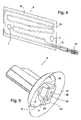
- Fig. 3 shows a perspective view of the inside of the Fig. 1
- One recognizes the two rectangular openings 8 and in each of these head portions 9 of the clamping body 6.
- the head portions 9 have a rectangular cross-section, which are substantially congruent with the cross section of the openings 8, but against this, so that they are firmly anchored in the wall.
- the visibility of the head sections 9 and their orientation makes it possible to recognize, in each step of the refrigeration device production following their attachment, that the clamping bodies 6 are located at the intended location and in the orientation required for their effectiveness in pressing the foil heating against the container shell.
- Fig. 4 is an enlarged perspective view of the film heater 5.
- This is composed of a base film of a thin, highly thermally conductive material, such as an aluminum foil, at their from the viewer in Fig. 4 opposite side carries an adhesive layer for adhering to the container shell 1.
- a resistance wire 11 is meandered on the base film 10.
- the resistance wire 11 is connected to a supply cable 13, which carries a connector 12, which allows a rapid contacting of the film heater 5 in the refrigeration device assembly.
- the heating wire 14 and the supply cable 13 are between the base sheet 10 and a view of the viewer Fig. 4 facing, not specifically illustrated cover, included. Since in the cover, unlike the base film 10, the thermal conductivity is of minor importance, various plastic materials can be used as cover, which have a much higher toughness than the aluminum foil and therefore contribute much to the mechanical robustness of the film heater 5.
- the Fig. 5 and 6 show in each case from different directions perspective views of a clamping body 6, which is provided to be anchored in an opening 8 of the container shell 1 and to press the film heater 5 against the container shell.
- the clamping body 6 is integrally molded from plastic by injection molding.
- From a circular base plate 15 is in one direction an anchoring pin 16 from, in turn from the base plate 15 to its free end, comprising: a foot portion 17 whose cross-section is in Fig. 7D is recognizable and has the shape of a rectangle with partly rounded, partly cut corners, a waist 18, the octagonal cross section also in Fig. 7D
- a transition portion 19 which is bounded in part by undercut triangular surfaces and of which an exemplary cross section in Fig. 7D is shown, and the head portion 9 in the form of a rectangle whose edge lengths such as the rectangle of the foot portion 16 correspond to the dimensions of the opening 8.
- the clamping body 6 is mounted on the container shell 1, in which first the head portion 9 is inserted through the opening 8, then pushed with slight bending of the edges of the opening 8 of the transition section 19 through the opening 8 and thereby the clamping body 6 is rotated, so that Finally, the rectangular surface of the foot portion 17 comes to rest in front of the opening 8 and engages in it.
- a conical skirt 22 is formed, the wall thickness is chosen low enough to make the skirt 22 flexible, so that when the foot portion 17 is engaged in the opening 8, the film heater 5 elastic against the container shell 1 presses.
- the clamping of the film heating between the skirt 22 and the container shell 1 secures the film heater 15 against delamination due to acting on the supply cable 13 during foaming tensile forces, since one of the two clamp body 6 is disposed in the immediate vicinity of the outlet of the supply cable 13 of the film heater 15 , Even if foam-forming material penetrates into any pockets between the film heater and the container shell, its foaming can not lead to detachment, since the two clamp body 6 prevent the film heater 15 from yielding to the pressure of expanding material in the bag, so that in the bag Foam-forming material that has penetrated largely foams out of the pocket during foaming, instead of enlarging it.
- Fig. 6 shows, from the back of the base plate 15 in extension of the anchoring pin 16, a mandrel 23 with laterally formed, parallel to the axis of rotation of the clamping body flights 24 from.
- the mandrel 23 and the wings 24 on the one hand have the function of serving as a handle in the assembly of the clamping body, which is comfortable to grip with the fingers and makes it possible to exert a required for locking the clamping body 6 of the opening 8 torque.
- the mandrel 23 and the vanes 24 are embedded in the space between the container shell 1 and the outer wall of the refrigerator in insulating foam material.
- the clamping body 6 is held non-rotatably and ensures permanent clamping of the film heater 5.
- head portion 9 Based on the protruding into the interior of the container shell 1 head portion 9 is verifiable at any time, whether the clamp body 6 are properly mounted, even if the outside of the container shell 1 is no longer accessible. The visibility of the head portions 9 is thus certain that the film heater 5 are correctly mounted and secured.
- a central bore 25 of the anchoring pin 16 allows plugging or screwing a cap (not shown), which covers the head portion 21 and not completely hidden by the opening 8 in the finished refrigerator.
- Two of the bore 25 in diametrical directions radiating slots 26 allow the insertion of a tool such as a screwdriver, with the help of the clamp body 6 can be tightened if necessary even after assembly of the housing of the refrigerator and before foaming subsequently.
Landscapes
- Engineering & Computer Science (AREA)
- General Engineering & Computer Science (AREA)
- Combustion & Propulsion (AREA)
- Physics & Mathematics (AREA)
- Mechanical Engineering (AREA)
- Thermal Sciences (AREA)
- Chemical & Material Sciences (AREA)
- Refrigerator Housings (AREA)
- Devices That Are Associated With Refrigeration Equipment (AREA)
- Cold Air Circulating Systems And Constructional Details In Refrigerators (AREA)
- Packages (AREA)
- Thermally Insulated Containers For Foods (AREA)
- Ultra Sonic Daignosis Equipment (AREA)
Description
- Die vorliegende Erfindung betrifft einen Innenbehälter für ein Kältegerät, insbesondere für ein Kühl-Gefrier-Kombinationsgerät.
- Die Gehäuse von Kältegeräten sind herkömmlicherweise aufgebaut aus einem Innenbehälter, meist in Form einer einteilig aus Kunststoffflachmaterial tiefgezogenen Schale, und einem äußeren Gehäuse, das meist aus Blechplatten zusammengesetzt ist und die zusammen einen Zwischenraum begrenzen, der mit einem thermisch isolierendem Schaummaterial ausgefüllt ist. Bei Kombinations-Kältegeräten, bei denen beide Temperaturzonen durch einen gleichen Kältemittelkreislauf gekühlt sind, in welchem Verdampfer dieser Zonen in Reihe angeordnet sind und vom Kältemittel durchströmt werden, ist es bekannt, der wärmeren der Zonen eine Heizeinrichtung zuzuordnen, um über diese die Arbeitsweise des Kältemittelkreislaufs zu beeinflussen. Eine solche Heizeinrichtung wird nötig, wenn ein derartiges Kombinations-Kältegerät in einer kühlen Umgebung eingesetzt wird, deren Temperatur nicht weit von der der wärmsten Zone des Kältegeräts entfernt ist. Eine solche niedrige Außentemperatur führt dazu, dass zum Kühlhalten besagter wärmster Zone nur sehr kurze Laufzeiten des Kältemittelkreislaufs erforderlich sind, die unzureichend sein können, um gleichzeitig eine kältere Zone des Geräts auf ihrer Solltemperatur zu halten. Das Heizelement dient dazu, in einer solchen Situation die wärmste Zone künstlich aufzuheizen, um so Laufzeiten des Kältemittelkreislaufs zu provozieren, die ausreichen, um auch die kältere Zone auf Solltemperatur zu halten.
- Das hierfür verwendete Heizelement hat meist die Form einer Folienheizung, mit einem zwischen flexible Folien eingebetteten Heizdraht, und ist an eine Außenfläche des Innenbehälters angeklebt, so dass es beim fertig montierten Kältegerät an seiner Außenseite von dem Schaummaterial umgeben ist. Während des Zusammenbaus des Kältegeräts kann sich das Problem ergeben, dass wenn die Verklebung des Heizelements unvollständig ist, lokale Ablösungen des Heizelements auftreten können, z.B. durch Eindringen des den Schaum bildenden Materials in Taschen zwischen der Folie und dem Innenbehälter und Aufschäumen des Materials in der Tasche, oder durch Zug an den elektrischen Versorgungsleitungen des Heizelements durch in dessen Umgebung expandierenden Schaum. Wenn solche Ablösungen auftreten, wird die vom Heizelement erzeugte Wärme nicht in der gewünschten Weise ins Innere des Kältegeräts abgegeben, und es kann zu lokalen Überhitzungen kommen, durch die der Isolierschaum beschädigt und in seiner Isolationswirkung beeinträchtigt wird. Der Stand der Technik bietet keine Möglichkeit, das Auftreten einer solchen Ablösung zu erkennen.
- Ein Innenbehälter gemäß Oberbegriff von Anspruch 1 ist aus
US-A-2 700 532 bekannt. - Aufgabe der vorliegenden Erfindung ist, einen Innenbehälter für ein Kältegerät zu schaffen, bei dem ein Heizelement wirksam gegen partielle (oder auch vollständige) Ablösung gesichert ist, und der es ermöglicht, die Wirksamkeit der Sicherung auch am fertig montierten Kältegerät zu erkennen.
- Die Aufgabe wird gelöst durch einen Innenbehälter mit dem Merkmal des Anspruchs 1. Der Klemmkörper bildet eine über die herkömmliche Verklebung hinausgehende Sicherung des Heizelements gegen Ablösung, und da er in einer Öffnung der Behälterschale verankert ist, ist es auch beim fertig montierten Kältegerät vom Innenraum der Behälterschale her problemlos möglich, das Vorhandensein des Klemmkörpers und damit die Wirksamkeit seiner Sicherung zu erkennen.
- Vorzugsweise erstreckt sich der wenigstens eine Klemmkörper durch eine Öffnung des Heizelements, so dass die zusätzliche Sicherung nicht nur auf Klemmung, sondern auch auf dem Eingriff des Klemmkörpers in das Heizelement basiert.
- Vorzugsweise weist der Klemmkörper einen Kern auf, der an der Öffnung der Behälterschale verankert ist, und eine Schürze, die den Kern ringsum umgibt, und die einen freien Rand aufweist, der elastisch gegen das Heizelement drückt. Diese Schürze bewirkt gleichzeitig eine Abdichtung der Öffnung der Behälterschale, wenn während der Montage des Kältegeräts der Zwischenraum zwischen der Behälterschale und der Außenwand des Geräts ausgeschäumt wird. Vorzugsweise erstreckt sich die Schürze in Form eines Kegels um den Kern.
- Als Schutz vor Ablösen durch Zug an dem Kabel des Heizelements ist vorzugsweise ein Klemmkörper benachbart zu dem Kabelanschluss platziert.
- Zweckmäßigerweise ist der Klemmkörper zwischen einer freien Orientierung, in der er in die Öffnung der Behälterschale einführbar bzw. aus ihr herausziehbar ist, und einer verankerten Orientierung drehbar, in der er das Heizelement gegen die Behälterschale gedrückt hält.
- Der Kern eines solchen Klemmkörpers hat vorzugsweise einen Aufbau mit einem Kopfabschnitt, einen Übergangsabschnitt, einer Taille und einem Fußabschnitt, die entlang der Drehachse aufeinanderfolgen, wobei der Kopfabschnitt einen ersten in der Öffnung der Behälterschale unverdrehbaren Querschnitt aufweist, der Fußabschnitt einen zweiten in der Öffnung unverdrehbaren Querschnitt aufweist, der aus dem ersten unverdrehbaren Querschnitt z.B. durch Drehung hervorgehen kann, die Taille einen Querschnitt aufweist, die nicht über die Schnittmenge der zwei unverdrehbaren Querschnitte hinausgeht, und der Übergangsabschnitt einen stetigen Übergang zwischen den Querschnitten der Taille und des Kopfabschnitts bildet. Die Länge der Taille sollte kleiner als die Wandstärke der Behälterschale sein, so dass diese zwischen dem Fußabschnitt und dem Übergangsabschnitt unter Spannung gehalten wird, wenn sich die Taille in der Öffnung befindet, um so eine Verriegelung des Fußabschnitts in der Öffnung zu erzielen.
- Der Klemmkörper sollte ferner wenigstens einen sich entlang der Drehachse erstreckenden Flügel aufweisen; ein solcher Flügel erleichtert das Eindrehen des Klemmkörpers in die Öffnung der Behälterschale, außerdem bewirkt er, wenn er beim fertig montierten Kältegerät in das Schaummaterial des Zwischenraums zwischen Behälterschale und Außengehäuse eintaucht, eine Immobilisierung des Klemmkörpers, die es letzterem unmöglich macht, sich aus der Öffnung zu lösen.
- Weitere Merkmale und Vorteile der Erfindung ergeben sich aus der nachfolgenden Beschreibung eines Ausführungsbeispiels unter Bezugnahme auf die beigefügten Figuren. Es zeigen:
- Fig. 1
- eine perspektivische Ansicht einer Behälterschale für ein Kältegerät gemäß der Erfindung;
- Fig. 2
- eine Detailansicht der Behälterschale mit daran montiertem Heizelement;
- Fig. 3
- eine Innenansicht der Behälterschale in Höhe des Heizelements;
- Fig. 4
- eine Detailansicht des Heizelements;
- Fig. 5
- eine perspektivische Ansicht eines zum Andrücken des Heizelements an die Behälterschale verwendeten Klemmkörpers, gesehen von seiner der Behälterschale zugewandten Seite aus;
- Fig. 6
- eine perspektivische Ansicht des Klemmkörpers, gesehen von seiner von der Behälterschale abgewandten Seite aus; und
- Fig. 7A-D
- eine Draufsicht auf den Kern des Klemmkörpers bzw. Schnitte durch diesen Kern in verschiedenen Höhen.
- Die in
Fig. 1 gezeigte Behälterschale 1 für ein Kältegerät ist ein durch Tiefziehen aus Kunststoff-Flachmaterial gebildetes einteiliges Element. Die Behälterschale 1 begrenzt zwei Lagerzonen. Eine kleinere Zone im oberen Bereich der Behälterschale 1 ist vorgesehen, um ein Gefrierfach 2 zu bilden, die darunter liegende größere Zone bildet ein Normalkühlfach 3. In die Seitenwände der Behälterschale 1 ist eine Mehrzahl von Öffnungen 4 geschnitten, die Aufhängungselemente (nicht dargestellt) für Fachböden, Teleskopauszüge oder dergleichen bilden sollen, die im Inneren des Normalkühlfachs 3 montiert werden sollen. Ein Heizelement in Form einer Folienheizung 5 ist an die Behälterschale 1 im unteren Bereich einer Seitenwand angeklebt. Zusätzlich zur Verklebung ist die Folienheizung 5 an der Behälterschale 1 durch zwei Klemmkörper 6 gehalten, auf deren Struktur und Funktion an späterer Stelle noch genauer eingegangen wird. -
Fig. 2 zeigt eine vergrößerte Ansicht des unteren Bereichs der Behälterschale 1 mit der daran festgeklebten Folienheizung 5. Einer der zwei Klemmkörper 6 ausFig. 1 ist inFig. 2 fortgelassen, so dass ein kreisrundes Loch 7 in der Folienheizung 5 und mittig in diesem Loch 7 eine rechteckige Öffnung 8 der Behälterschale 1 erkennbar ist, die zur Verankerung des in der Figur weggelassenen Klemmkörpers 6 dient. Ein entsprechendes Loch 7 und eine entsprechende Öffnung 8 sind auch durch den dargestellten Klemmkörper 6 verdeckt. -
Fig. 3 zeigt einen perspektivischen Blick auf die Innenseite der inFig. 1 dem Betrachter zugewandten Seitenwand der Behälterschale 1. Man erkennt die zwei rechteckigen Öffnungen 8 und in diesen jeweils Kopfabschnitte 9 der Klemmkörper 6. Die Kopfabschnitte 9 haben einen rechteckigen Querschnitt, der mit dem Querschnitt der Öffnungen 8 im wesentlichen deckungsgleich, allerdings gegen diese verdreht sind, so dass sie in der Wand fest verankert sind. Die Sichtbarkeit der Kopfabschnitte 9 und ihre Orientierung erlaubt es, in jeder auf ihrer Anbringung folgenden Stufe der Kältegerätefertigung zu erkennen, dass die Klemmkörper 6 sich am vorgesehenen Platz und in der für ihre Wirksamkeit zum Drücken der Folienheizung gegen die Behälterschale erforderlichen Orientierung befinden. -
Fig. 4 ist eine vergrößerte perspektivische Ansicht der Folienheizung 5. Diese ist aufgebaut aus einer Basisfolie aus einem dünnen, gut wärmeleitenden Material, z.B. einer Aluminiumfolie, die an ihrer vom Betrachter inFig. 4 abgewandten Seite eine Klebstoffschicht zum Anheften an die Behälterschale 1 trägt. Ein Widerstandsdraht 11 ist mäanderartig auf der Basisfolie 10 angeordnet. Der Widerstandsdraht 11 ist an ein Versorgungskabel 13 angeschlossen, das einen Steckverbinder 12 trägt, der bei der Kältegerätemontage eine schnelle Kontaktierung der Folienheizung 5 ermöglicht. Der Heizdraht 14 und das Versorgungskabel 13 sind zwischen der Basisfolie 10 und einer dem Betrachter derFig. 4 zugewandten, nicht eigens dargestellten Abdeckfolie, eingeschlossen. Da bei der Abdeckfolie, anders als bei der Basisfolie 10, die Wärmeleitfähigkeit von untergeordneter Bedeutung ist, können als Abdeckfolie diverse Kunststoffmaterialien eingesetzt werden, die eine wesentlich höhere Zähigkeit als die Aluminiumfolie besitzen und daher viel zur mechanischen Robustheit der Folienheizung 5 beitragen. - Die
Fig. 5 und6 zeigen jeweils aus verschiedenen Richtungen perspektivische Ansichten eines Klemmkörpers 6, der vorgesehen ist, um in einer Öffnung 8 der Behälterschale 1 verankert zu werden und die Folienheizung 5 gegen die Behälterschale zu drücken. Der Klemmkörper 6 ist einteilig aus Kunststoff im Spritzguss geformt. Von einer kreisrunden Grundplatte 15 steht in einer Richtung ein Verankerungszapfen 16 ab, der der Reihe nach von der Grundplatte 15 bis zu seinem freien Ende, aufweist: Einen Fußabschnitt 17, dessen Querschnitt inFig. 7D zu erkennen ist und die Form eines Rechtsecks mit teils abgerundeten, teils abgeschnittenen Ecken hat, eine Taille 18, deren achteckiger Querschnitt ebenfalls inFig. 7D zu sehen ist, einen Übergangsabschnitt 19, der zum Teil durch hinterschnittene Dreieckflächen begrenzt ist und von dem ein exemplarischer Querschnitt inFig. 7D gezeigt ist, und den Kopfabschnitt 9 in Form eines Rechtecks, dessen Kantenlängen wie die des Rechtecks des Fußabschnitts 16 den Abmessungen der Öffnung 8 entsprechen. - Der Klemmkörper 6 wird an der Behälterschale 1 montiert, in dem zunächst der Kopfabschnitt 9 durch dessen Öffnung 8 gesteckt wird, anschließend unter geringfügiger Verbiegung der Ränder der Öffnung 8 der Übergangsabschnitt 19 durch die Öffnung 8 geschoben und dabei der Klemmkörper 6 verdreht wird, so dass schließlich die Rechteckfläche des Fußabschnitts 17 vor der Öffnung 8 zum Liegen kommt und in diese einrastet.
- An dem Rand der Grundplatte 15 ist eine kegelförmige Schürze 22 angeformt, deren Wandstärke gering genug gewählt ist, um die Schürze 22 flexibel zu machen, so dass diese, wenn der Fußabschnitt 17 in die Öffnung 8 eingerastet ist, die Folienheizung 5 elastisch gegen die Behälterschale 1 drückt. Die Klemmung der Folienheizung zwischen der Schürze 22 und der Behälterschale 1 sichert die Folienheizung 15 gegen Ablösung aufgrund von während des Ausschäumens auf das Versorgungskabel 13 wirkenden Zugkräften, da einer der zwei Klemmkörper 6 in unmittelbarer Nähe des Abgangs des Versorgungskabels 13 von der Folienheizung 15 angeordnet ist. Auch wenn schaumbildendes Material in eventuelle Taschen zwischen der Folienheizung und der Behälterschale eindringt, kann dessen Aufschäumen nicht zu einer Ablösung führen, da die zwei Klemmkörper 6 die Folienheizung 15 daran hindern, dem Druck des in der Tasche expandierenden Materials nachzugeben, so dass in die Tasche eingedrungenes schaumbildendes Material beim Aufschäumen größtenteils aus der Tasche wieder herausdringt, anstatt diese zu vergrößern.
- Anstelle der exemplarisch dargestellten zwei Klemmkörper 6 an gegenüberliegenden Längsenden der Folienheizung 5 könnte selbstverständlich auch eine größere Zahl von Klemmkörpern, z.B. einer in jeder Ecke der Folienheizung, vorgesehen werden.
- Wie
Fig. 6 zeigt, steht von der Rückseite der Grundplatte 15 in Verlängerung des Verankerungszapfens 16 ein Dorn 23 mit seitlich angeformten, zur Drehachse des Klemmkörpers parallelen Flügen 24 ab. Der Dorn 23 und die Flügel 24 haben einerseits die Funktion, als Handhabe bei der Montage des Klemmkörpers zu dienen, die bequem mit den Fingern zu greifen ist und es ermöglicht, ein zum Verrasten des Klemmkörpers 6 der Öffnung 8 erforderliches Drehmoment auszuüben. Wenn die Montage des Kältegeräts abgeschlossen ist, sind der Dorn 23 und die Flügel 24 im Zwischenraum zwischen der Behälterschale 1 und der Außenwand des Kältegeräts in isolierendes Schaummaterial eingebettet. Dadurch ist nach Abschluss der Montage der Klemmkörper 6 unverdrehbar gehalten und sorgt für eine dauerhafte Klemmung der Folienheizung 5. - Anhand des ins Innere der Behälterschale 1 hineinragenden Kopfabschnitts 9 ist jederzeit nachprüfbar, ob die Klemmkörper 6 ordnungsgemäß montiert sind, auch wenn die Außenseite der Behälterschale 1 nicht mehr zugänglich ist. Die Sichtbarkeit der Kopfabschnitte 9 gibt somit Gewissheit, dass die Folienheizung 5 korrekt montiert und gesichert sind.
- Eine zentrale Bohrung 25 des Verankerungszapfens 16 erlaubt das Aufstecken oder Verschrauben einer (nicht dargestellten) Kappe, die beim fertigen Kältegerät den Kopfabschnitt 21 und die von ihm nicht vollständig verdeckte Öffnung 8 überdeckt.
- Zwei von der Bohrung 25 in diametrale Richtungen ausstrahlende Schlitze 26 ermöglichen das Einführen eines Werkzeugs wie etwa eines Schraubendrehers, mit dessen Hilfe der Klemmkörper 6 im Bedarfsfall auch noch nach dem Zusammenbau des Gehäuses des Kältegeräts und vor dem Ausschäumen nachträglich festgezogen werden kann.
Claims (11)
- Innenbehälter für ein Kältegerät, mit einer Behälterschale (1) und einem an einer Außenseite der Behälterschale (1) befestigten Heizelement (5), dadurch gekennzeichnet, dass wenigstens ein Klemmkörper (6) in einer Öffnung (8) der Behälterschale (1) verankert ist und das Heizelement (5) gegen die Behälterschale (1) gedrückt hält.
- Innenbehälter nach Anspruch 1, dadurch gekennzeichnet, dass das Heizelement (5) an der Behälterschale (1) durch Klebung befestigt ist.
- Innenbehälter nach einem der vorhergehenden Ansprüche, dadurch gekennzeichnet, dass das Heizelement (5) wenigstens eine Öffnung (7) aufweist, durch die sich der Klemmkörper (6) erstreckt.
- Innenbehälter nach einem der vorhergehenden Ansprüche, dadurch gekennzeichnet, dass der Klemmkörper (6) einen Kern (16), der an der Öffnung (8) der Behälterschale (1) verankert ist, und eine Schürze (22) aufweist. die den Kern (16) ringsum umgibt und die einen freien Rand aufweist, der elastisch gegen das Heizelement (5) drückt.
- Innenbehälter nach Anspruch 4, dadurch gekennzeichnet, dass die Schürze (22) kegelförmig ist.
- Innenbehälter nach einem der vorhergehenden Ansprüche, dadurch gekennzeichnet, dass der wenigsten eine Klemmkörper (6) benachbart zu einem Kabelanschluss des Heizelements (5) platziert ist.
- Innenbehälter nach einem der vorhergehenden Ansprüche, dadurch gekennzeichnet, dass der Klemmkörper (6) zwischen einer freien Orientierung, in der er in die Öffnung (8) der Behälterschale (1) einführbar bzw. aus ihr herausziehbar ist, und einer verankerten Orientierung drehbar ist, in der er das Heizelement (5) gegen die Behälterschale (1) gedrückt hält.
- Innenbehälter nach Anspruch 7, dadurch gekennzeichnet, dass ein sich durch die Öffnung (8) der Behälterschale (1) erstreckender Kern (16) des Klemmkörpers einen Kopfabschnitt (9) mit einem ersten in der Öffnung (8) unverdrehbaren Querschnitt, einen Fußabschnitt (17) mit einem zweiten in der Öffnung (8) unverdrehbaren Querschnitt, eine an den Fußabschnitt (17) angrenzende Taille (18), deren Querschnitt nicht über die Schnittmenge der zwei unverdrehbaren Querschnitte hinausgeht, und einen Übergangsabschnitt (19) zwischen der Taille (18) und dem Kopfabschnitt (9) aufweist, dessen Querschnitt stetig vom ersten unverdrehbaren Querschnitt in den Querschnitt der Taille (18) übergeht, und dass die Länge der Taille (18) kleiner als die Wandstärke der Behälterschale (1) ist.
- Innenbehälter nach Anspruch 7 oder 8, dadurch gekennzeichnet, dass der Klemmkörper (6) wenigstens einen Flügel (24) aufweist, der sich entlang der Achse erstreckt, um die der Klemmkörper (6) drehbar ist.
- Kältegerät mit einem Innenbehälter nach einem der vorhergehenden Ansprüche.
- Kältegerät mit einem Innenbehälter nach Anspruch 9, dadurch gekennzeichnet, dass der Flügel (24) durch in einem Zwischenraum zwischen der Behälterschale (1) und einer Außenwand eingebrachtes Isoliermaterial immobilisiert ist.
Applications Claiming Priority (3)
| Application Number | Priority Date | Filing Date | Title |
|---|---|---|---|
| DE10259765A DE10259765A1 (de) | 2002-12-19 | 2002-12-19 | Innenbehälter für ein Kältegerät |
| DE10259765 | 2002-12-19 | ||
| PCT/EP2003/014096 WO2004057251A1 (de) | 2002-12-19 | 2003-12-11 | Innenbehälter für ein kältegerät |
Publications (2)
| Publication Number | Publication Date |
|---|---|
| EP1576327A1 EP1576327A1 (de) | 2005-09-21 |
| EP1576327B1 true EP1576327B1 (de) | 2009-12-09 |
Family
ID=32404007
Family Applications (1)
| Application Number | Title | Priority Date | Filing Date |
|---|---|---|---|
| EP03789233A Expired - Lifetime EP1576327B1 (de) | 2002-12-19 | 2003-12-11 | Innenbehälter für ein kältegerät |
Country Status (7)
| Country | Link |
|---|---|
| EP (1) | EP1576327B1 (de) |
| CN (1) | CN1754077A (de) |
| AT (1) | ATE451587T1 (de) |
| AU (1) | AU2003293849A1 (de) |
| DE (2) | DE10259765A1 (de) |
| ES (1) | ES2336098T3 (de) |
| WO (1) | WO2004057251A1 (de) |
Families Citing this family (4)
| Publication number | Priority date | Publication date | Assignee | Title |
|---|---|---|---|---|
| US7191827B2 (en) * | 2002-12-30 | 2007-03-20 | Whirlpool Corporation | Low ambient temperature refrigerator |
| DE102006012921A1 (de) * | 2006-03-21 | 2007-09-27 | BSH Bosch und Siemens Hausgeräte GmbH | Bauteil zur Montage an einer Wand und damit ausgestattetes Gerätegehäuse |
| ITMI20060132U1 (it) * | 2006-04-07 | 2007-10-08 | Whirlpool Co | Disposizione per asportare velocemente la condensa della parete a minor temperatura di un vano a 0°c in un frigorifero |
| ITRN20100016A1 (it) * | 2010-04-08 | 2011-10-09 | Indesit Co Spa | Metodo di produzione di una cella frigorifera e dispositivo di refrigerazione comprendente detta cella frigorifera |
Family Cites Families (7)
| Publication number | Priority date | Publication date | Assignee | Title |
|---|---|---|---|---|
| US2700532A (en) * | 1952-03-22 | 1955-01-25 | Philco Corp | Temperature control apparatus for refrigerators |
| US3802476A (en) * | 1972-05-08 | 1974-04-09 | Illinois Tool Works | Screw anchor |
| JPH04257684A (ja) * | 1991-02-13 | 1992-09-11 | Toshiba Corp | 冷蔵庫 |
| JP2001050633A (ja) * | 1999-08-12 | 2001-02-23 | Hitachi Ltd | 冷蔵庫 |
| KR100381660B1 (ko) * | 2000-09-21 | 2003-04-26 | 위니아만도 주식회사 | 김치저장고의 야채실 히팅구조 |
| DE10058400A1 (de) * | 2000-11-24 | 2002-05-29 | Bsh Bosch Siemens Hausgeraete | Verfahren zum schaumdichten Befestigen eines Körpers an einer Wand |
| DE10221898B4 (de) * | 2002-05-16 | 2005-01-27 | BSH Bosch und Siemens Hausgeräte GmbH | Kältegerät mit beheizbarem Innenraum |
-
2002
- 2002-12-19 DE DE10259765A patent/DE10259765A1/de not_active Withdrawn
-
2003
- 2003-12-11 CN CN200380109871.7A patent/CN1754077A/zh active Pending
- 2003-12-11 ES ES03789233T patent/ES2336098T3/es not_active Expired - Lifetime
- 2003-12-11 AT AT03789233T patent/ATE451587T1/de not_active IP Right Cessation
- 2003-12-11 AU AU2003293849A patent/AU2003293849A1/en not_active Abandoned
- 2003-12-11 EP EP03789233A patent/EP1576327B1/de not_active Expired - Lifetime
- 2003-12-11 WO PCT/EP2003/014096 patent/WO2004057251A1/de not_active Ceased
- 2003-12-11 DE DE50312221T patent/DE50312221D1/de not_active Expired - Lifetime
Also Published As
| Publication number | Publication date |
|---|---|
| AU2003293849A1 (en) | 2004-07-14 |
| ATE451587T1 (de) | 2009-12-15 |
| WO2004057251A1 (de) | 2004-07-08 |
| DE10259765A1 (de) | 2004-07-01 |
| DE50312221D1 (de) | 2010-01-21 |
| ES2336098T3 (es) | 2010-04-08 |
| CN1754077A (zh) | 2006-03-29 |
| EP1576327A1 (de) | 2005-09-21 |
Similar Documents
| Publication | Publication Date | Title |
|---|---|---|
| EP2705315B2 (de) | Kältegerät, insbesondere haushaltskältegerät | |
| EP1430261B1 (de) | Gehäuse für ein kältegerät | |
| EP1639303A1 (de) | Tür mit isolierverglasung und damit ausgestattetes haushalts gerät | |
| DE102008054590A1 (de) | Kältegerät mit einer Eis- und/oder Flüssigkeitsausgabevorrichtung | |
| EP2593737A2 (de) | Gehäusekomponente für ein kältegerät | |
| EP2906888B1 (de) | Kältegerät mit einbauteil | |
| EP1576327B1 (de) | Innenbehälter für ein kältegerät | |
| WO2009000335A1 (de) | Kältegerät und verfahren zu dessen montage | |
| WO2013076003A2 (de) | Wärmeisolationsgehäuse für ein kältegerät | |
| DE10221898B4 (de) | Kältegerät mit beheizbarem Innenraum | |
| EP1430260A1 (de) | Kältegerät mit coldwall-verdampfer | |
| EP3457056A1 (de) | Türabsteller für ein Kältergerät | |
| WO2012007282A2 (de) | Gehäusekomponente für ein kältegerät | |
| EP1155268B1 (de) | Kältegerätetür | |
| WO2012113625A1 (de) | Kältegerät mit rückwandverflüssiger | |
| WO2005064249A1 (de) | Gehäuse für ein kältegerät | |
| DE19709857A1 (de) | Dichtungselement | |
| WO2012150159A2 (de) | Wärmeisolierende wand | |
| WO2009117998A2 (de) | Verfahren zur isolierung einer batterie | |
| EP1866585B1 (de) | Kühl- und/oder gefriergerät | |
| WO2016078894A1 (de) | Kältegerät mit einem kaltluftkanal | |
| DE202014005490U1 (de) | Kältegerät, insbesondere Haushaltskältegerät | |
| DE2915297C2 (de) | Kühlmöbel, insbesondere Mehrtemperaturen-Kühlschrank | |
| DE102013220304A1 (de) | Haushaltsgerät mit einem eine Elektroniktasche und einen Deckel dazu aufweisenden Gehäuse | |
| EP1898169A2 (de) | Frontplatte für ein Haushaltsgerät |
Legal Events
| Date | Code | Title | Description |
|---|---|---|---|
| PUAI | Public reference made under article 153(3) epc to a published international application that has entered the european phase |
Free format text: ORIGINAL CODE: 0009012 |
|
| 17P | Request for examination filed |
Effective date: 20050719 |
|
| AK | Designated contracting states |
Kind code of ref document: A1 Designated state(s): AT BE BG CH CY CZ DE DK EE ES FI FR GB GR HU IE IT LI LU MC NL PT RO SE SI SK TR |
|
| AX | Request for extension of the european patent |
Extension state: AL LT LV MK |
|
| DAX | Request for extension of the european patent (deleted) | ||
| RIN1 | Information on inventor provided before grant (corrected) |
Inventor name: LAIBLE, KARL-FRIEDRICH Inventor name: KENTNER, WOLFGANG |
|
| GRAP | Despatch of communication of intention to grant a patent |
Free format text: ORIGINAL CODE: EPIDOSNIGR1 |
|
| GRAS | Grant fee paid |
Free format text: ORIGINAL CODE: EPIDOSNIGR3 |
|
| GRAA | (expected) grant |
Free format text: ORIGINAL CODE: 0009210 |
|
| AK | Designated contracting states |
Kind code of ref document: B1 Designated state(s): AT BE BG CH CY CZ DE DK EE ES FI FR GB GR HU IE IT LI LU MC NL PT RO SE SI SK TR |
|
| REG | Reference to a national code |
Ref country code: GB Ref legal event code: FG4D Free format text: NOT ENGLISH |
|
| REG | Reference to a national code |
Ref country code: CH Ref legal event code: EP |
|
| REG | Reference to a national code |
Ref country code: IE Ref legal event code: FG4D |
|
| REF | Corresponds to: |
Ref document number: 50312221 Country of ref document: DE Date of ref document: 20100121 Kind code of ref document: P |
|
| REG | Reference to a national code |
Ref country code: ES Ref legal event code: FG2A Ref document number: 2336098 Country of ref document: ES Kind code of ref document: T3 |
|
| REG | Reference to a national code |
Ref country code: NL Ref legal event code: VDEP Effective date: 20091209 |
|
| PG25 | Lapsed in a contracting state [announced via postgrant information from national office to epo] |
Ref country code: SE Free format text: LAPSE BECAUSE OF FAILURE TO SUBMIT A TRANSLATION OF THE DESCRIPTION OR TO PAY THE FEE WITHIN THE PRESCRIBED TIME-LIMIT Effective date: 20091209 Ref country code: FI Free format text: LAPSE BECAUSE OF FAILURE TO SUBMIT A TRANSLATION OF THE DESCRIPTION OR TO PAY THE FEE WITHIN THE PRESCRIBED TIME-LIMIT Effective date: 20091209 |
|
| PG25 | Lapsed in a contracting state [announced via postgrant information from national office to epo] |
Ref country code: SI Free format text: LAPSE BECAUSE OF FAILURE TO SUBMIT A TRANSLATION OF THE DESCRIPTION OR TO PAY THE FEE WITHIN THE PRESCRIBED TIME-LIMIT Effective date: 20091209 |
|
| BERE | Be: lapsed |
Owner name: BSH BOSCH UND SIEMENS HAUSGERATE G.M.B.H. Effective date: 20091231 |
|
| REG | Reference to a national code |
Ref country code: IE Ref legal event code: FD4D |
|
| PG25 | Lapsed in a contracting state [announced via postgrant information from national office to epo] |
Ref country code: RO Free format text: LAPSE BECAUSE OF FAILURE TO SUBMIT A TRANSLATION OF THE DESCRIPTION OR TO PAY THE FEE WITHIN THE PRESCRIBED TIME-LIMIT Effective date: 20091209 Ref country code: MC Free format text: LAPSE BECAUSE OF NON-PAYMENT OF DUE FEES Effective date: 20100701 Ref country code: BG Free format text: LAPSE BECAUSE OF FAILURE TO SUBMIT A TRANSLATION OF THE DESCRIPTION OR TO PAY THE FEE WITHIN THE PRESCRIBED TIME-LIMIT Effective date: 20100309 Ref country code: EE Free format text: LAPSE BECAUSE OF FAILURE TO SUBMIT A TRANSLATION OF THE DESCRIPTION OR TO PAY THE FEE WITHIN THE PRESCRIBED TIME-LIMIT Effective date: 20091209 Ref country code: IE Free format text: LAPSE BECAUSE OF FAILURE TO SUBMIT A TRANSLATION OF THE DESCRIPTION OR TO PAY THE FEE WITHIN THE PRESCRIBED TIME-LIMIT Effective date: 20091209 Ref country code: PT Free format text: LAPSE BECAUSE OF FAILURE TO SUBMIT A TRANSLATION OF THE DESCRIPTION OR TO PAY THE FEE WITHIN THE PRESCRIBED TIME-LIMIT Effective date: 20100409 Ref country code: NL Free format text: LAPSE BECAUSE OF FAILURE TO SUBMIT A TRANSLATION OF THE DESCRIPTION OR TO PAY THE FEE WITHIN THE PRESCRIBED TIME-LIMIT Effective date: 20091209 |
|
| REG | Reference to a national code |
Ref country code: CH Ref legal event code: PL |
|
| PG25 | Lapsed in a contracting state [announced via postgrant information from national office to epo] |
Ref country code: SK Free format text: LAPSE BECAUSE OF FAILURE TO SUBMIT A TRANSLATION OF THE DESCRIPTION OR TO PAY THE FEE WITHIN THE PRESCRIBED TIME-LIMIT Effective date: 20091209 Ref country code: CZ Free format text: LAPSE BECAUSE OF FAILURE TO SUBMIT A TRANSLATION OF THE DESCRIPTION OR TO PAY THE FEE WITHIN THE PRESCRIBED TIME-LIMIT Effective date: 20091209 |
|
| PLBE | No opposition filed within time limit |
Free format text: ORIGINAL CODE: 0009261 |
|
| STAA | Information on the status of an ep patent application or granted ep patent |
Free format text: STATUS: NO OPPOSITION FILED WITHIN TIME LIMIT |
|
| PG25 | Lapsed in a contracting state [announced via postgrant information from national office to epo] |
Ref country code: LI Free format text: LAPSE BECAUSE OF NON-PAYMENT OF DUE FEES Effective date: 20091231 Ref country code: BE Free format text: LAPSE BECAUSE OF NON-PAYMENT OF DUE FEES Effective date: 20091231 Ref country code: CH Free format text: LAPSE BECAUSE OF NON-PAYMENT OF DUE FEES Effective date: 20091231 Ref country code: CY Free format text: LAPSE BECAUSE OF FAILURE TO SUBMIT A TRANSLATION OF THE DESCRIPTION OR TO PAY THE FEE WITHIN THE PRESCRIBED TIME-LIMIT Effective date: 20091209 Ref country code: GR Free format text: LAPSE BECAUSE OF FAILURE TO SUBMIT A TRANSLATION OF THE DESCRIPTION OR TO PAY THE FEE WITHIN THE PRESCRIBED TIME-LIMIT Effective date: 20100310 |
|
| 26N | No opposition filed |
Effective date: 20100910 |
|
| PG25 | Lapsed in a contracting state [announced via postgrant information from national office to epo] |
Ref country code: DK Free format text: LAPSE BECAUSE OF FAILURE TO SUBMIT A TRANSLATION OF THE DESCRIPTION OR TO PAY THE FEE WITHIN THE PRESCRIBED TIME-LIMIT Effective date: 20091209 |
|
| PG25 | Lapsed in a contracting state [announced via postgrant information from national office to epo] |
Ref country code: LU Free format text: LAPSE BECAUSE OF NON-PAYMENT OF DUE FEES Effective date: 20091211 |
|
| PG25 | Lapsed in a contracting state [announced via postgrant information from national office to epo] |
Ref country code: AT Free format text: LAPSE BECAUSE OF NON-PAYMENT OF DUE FEES Effective date: 20091211 |
|
| PG25 | Lapsed in a contracting state [announced via postgrant information from national office to epo] |
Ref country code: HU Free format text: LAPSE BECAUSE OF FAILURE TO SUBMIT A TRANSLATION OF THE DESCRIPTION OR TO PAY THE FEE WITHIN THE PRESCRIBED TIME-LIMIT Effective date: 20100610 |
|
| REG | Reference to a national code |
Ref country code: DE Ref legal event code: R081 Ref document number: 50312221 Country of ref document: DE Owner name: BSH HAUSGERAETE GMBH, DE Free format text: FORMER OWNER: BSH BOSCH UND SIEMENS HAUSGERAETE GMBH, 81739 MUENCHEN, DE Effective date: 20150407 |
|
| REG | Reference to a national code |
Ref country code: ES Ref legal event code: PC2A Owner name: BSH HAUSGERATE GMBH Effective date: 20150527 |
|
| REG | Reference to a national code |
Ref country code: FR Ref legal event code: CD Owner name: BSH HAUSGERATE GMBH Effective date: 20151022 |
|
| REG | Reference to a national code |
Ref country code: FR Ref legal event code: PLFP Year of fee payment: 13 |
|
| REG | Reference to a national code |
Ref country code: FR Ref legal event code: PLFP Year of fee payment: 14 |
|
| PGFP | Annual fee paid to national office [announced via postgrant information from national office to epo] |
Ref country code: GB Payment date: 20161222 Year of fee payment: 14 |
|
| PGFP | Annual fee paid to national office [announced via postgrant information from national office to epo] |
Ref country code: FR Payment date: 20161221 Year of fee payment: 14 Ref country code: ES Payment date: 20161221 Year of fee payment: 14 |
|
| PGFP | Annual fee paid to national office [announced via postgrant information from national office to epo] |
Ref country code: TR Payment date: 20171211 Year of fee payment: 15 |
|
| PGFP | Annual fee paid to national office [announced via postgrant information from national office to epo] |
Ref country code: DE Payment date: 20171231 Year of fee payment: 15 |
|
| GBPC | Gb: european patent ceased through non-payment of renewal fee |
Effective date: 20171211 |
|
| REG | Reference to a national code |
Ref country code: FR Ref legal event code: ST Effective date: 20180831 |
|
| PG25 | Lapsed in a contracting state [announced via postgrant information from national office to epo] |
Ref country code: FR Free format text: LAPSE BECAUSE OF NON-PAYMENT OF DUE FEES Effective date: 20180102 |
|
| PG25 | Lapsed in a contracting state [announced via postgrant information from national office to epo] |
Ref country code: GB Free format text: LAPSE BECAUSE OF NON-PAYMENT OF DUE FEES Effective date: 20171211 |
|
| PGFP | Annual fee paid to national office [announced via postgrant information from national office to epo] |
Ref country code: IT Payment date: 20181218 Year of fee payment: 16 |
|
| REG | Reference to a national code |
Ref country code: DE Ref legal event code: R119 Ref document number: 50312221 Country of ref document: DE |
|
| REG | Reference to a national code |
Ref country code: ES Ref legal event code: FD2A Effective date: 20190703 |
|
| PG25 | Lapsed in a contracting state [announced via postgrant information from national office to epo] |
Ref country code: ES Free format text: LAPSE BECAUSE OF NON-PAYMENT OF DUE FEES Effective date: 20171212 |
|
| PG25 | Lapsed in a contracting state [announced via postgrant information from national office to epo] |
Ref country code: DE Free format text: LAPSE BECAUSE OF NON-PAYMENT OF DUE FEES Effective date: 20190702 |
|
| PG25 | Lapsed in a contracting state [announced via postgrant information from national office to epo] |
Ref country code: IT Free format text: LAPSE BECAUSE OF NON-PAYMENT OF DUE FEES Effective date: 20191211 |
|
| PG25 | Lapsed in a contracting state [announced via postgrant information from national office to epo] |
Ref country code: TR Free format text: LAPSE BECAUSE OF NON-PAYMENT OF DUE FEES Effective date: 20191211 |