EP1575455B1 - Künstliches gelenk - Google Patents
Künstliches gelenk Download PDFInfo
- Publication number
- EP1575455B1 EP1575455B1 EP03782141A EP03782141A EP1575455B1 EP 1575455 B1 EP1575455 B1 EP 1575455B1 EP 03782141 A EP03782141 A EP 03782141A EP 03782141 A EP03782141 A EP 03782141A EP 1575455 B1 EP1575455 B1 EP 1575455B1
- Authority
- EP
- European Patent Office
- Prior art keywords
- joint
- projection
- recess
- artificial joint
- overlay
- Prior art date
- Legal status (The legal status is an assumption and is not a legal conclusion. Google has not performed a legal analysis and makes no representation as to the accuracy of the status listed.)
- Expired - Lifetime
Links
Images

Classifications
-
- A—HUMAN NECESSITIES
- A61—MEDICAL OR VETERINARY SCIENCE; HYGIENE
- A61F—FILTERS IMPLANTABLE INTO BLOOD VESSELS; PROSTHESES; DEVICES PROVIDING PATENCY TO, OR PREVENTING COLLAPSING OF, TUBULAR STRUCTURES OF THE BODY, e.g. STENTS; ORTHOPAEDIC, NURSING OR CONTRACEPTIVE DEVICES; FOMENTATION; TREATMENT OR PROTECTION OF EYES OR EARS; BANDAGES, DRESSINGS OR ABSORBENT PADS; FIRST-AID KITS
- A61F2/00—Filters implantable into blood vessels; Prostheses, i.e. artificial substitutes or replacements for parts of the body; Appliances for connecting them with the body; Devices providing patency to, or preventing collapsing of, tubular structures of the body, e.g. stents
- A61F2/02—Prostheses implantable into the body
- A61F2/30—Joints
- A61F2/38—Joints for elbows or knees
- A61F2/389—Tibial components
-
- A—HUMAN NECESSITIES
- A61—MEDICAL OR VETERINARY SCIENCE; HYGIENE
- A61F—FILTERS IMPLANTABLE INTO BLOOD VESSELS; PROSTHESES; DEVICES PROVIDING PATENCY TO, OR PREVENTING COLLAPSING OF, TUBULAR STRUCTURES OF THE BODY, e.g. STENTS; ORTHOPAEDIC, NURSING OR CONTRACEPTIVE DEVICES; FOMENTATION; TREATMENT OR PROTECTION OF EYES OR EARS; BANDAGES, DRESSINGS OR ABSORBENT PADS; FIRST-AID KITS
- A61F2/00—Filters implantable into blood vessels; Prostheses, i.e. artificial substitutes or replacements for parts of the body; Appliances for connecting them with the body; Devices providing patency to, or preventing collapsing of, tubular structures of the body, e.g. stents
- A61F2/02—Prostheses implantable into the body
- A61F2/30—Joints
- A61F2/46—Special tools for implanting artificial joints
- A61F2/4637—Special tools for implanting artificial joints for connecting or disconnecting two parts of a prosthesis
-
- A—HUMAN NECESSITIES
- A61—MEDICAL OR VETERINARY SCIENCE; HYGIENE
- A61F—FILTERS IMPLANTABLE INTO BLOOD VESSELS; PROSTHESES; DEVICES PROVIDING PATENCY TO, OR PREVENTING COLLAPSING OF, TUBULAR STRUCTURES OF THE BODY, e.g. STENTS; ORTHOPAEDIC, NURSING OR CONTRACEPTIVE DEVICES; FOMENTATION; TREATMENT OR PROTECTION OF EYES OR EARS; BANDAGES, DRESSINGS OR ABSORBENT PADS; FIRST-AID KITS
- A61F2/00—Filters implantable into blood vessels; Prostheses, i.e. artificial substitutes or replacements for parts of the body; Appliances for connecting them with the body; Devices providing patency to, or preventing collapsing of, tubular structures of the body, e.g. stents
- A61F2/02—Prostheses implantable into the body
- A61F2/30—Joints
- A61F2002/30001—Additional features of subject-matter classified in A61F2/28, A61F2/30 and subgroups thereof
- A61F2002/30003—Material related properties of the prosthesis or of a coating on the prosthesis
- A61F2002/30004—Material related properties of the prosthesis or of a coating on the prosthesis the prosthesis being made from materials having different values of a given property at different locations within the same prosthesis
- A61F2002/30037—Material related properties of the prosthesis or of a coating on the prosthesis the prosthesis being made from materials having different values of a given property at different locations within the same prosthesis differing in coefficient of thermal expansion or dila(ta)tion
-
- A—HUMAN NECESSITIES
- A61—MEDICAL OR VETERINARY SCIENCE; HYGIENE
- A61F—FILTERS IMPLANTABLE INTO BLOOD VESSELS; PROSTHESES; DEVICES PROVIDING PATENCY TO, OR PREVENTING COLLAPSING OF, TUBULAR STRUCTURES OF THE BODY, e.g. STENTS; ORTHOPAEDIC, NURSING OR CONTRACEPTIVE DEVICES; FOMENTATION; TREATMENT OR PROTECTION OF EYES OR EARS; BANDAGES, DRESSINGS OR ABSORBENT PADS; FIRST-AID KITS
- A61F2/00—Filters implantable into blood vessels; Prostheses, i.e. artificial substitutes or replacements for parts of the body; Appliances for connecting them with the body; Devices providing patency to, or preventing collapsing of, tubular structures of the body, e.g. stents
- A61F2/02—Prostheses implantable into the body
- A61F2/30—Joints
- A61F2002/30001—Additional features of subject-matter classified in A61F2/28, A61F2/30 and subgroups thereof
- A61F2002/30108—Shapes
- A61F2002/3011—Cross-sections or two-dimensional shapes
- A61F2002/30112—Rounded shapes, e.g. with rounded corners
- A61F2002/30133—Rounded shapes, e.g. with rounded corners kidney-shaped or bean-shaped
-
- A—HUMAN NECESSITIES
- A61—MEDICAL OR VETERINARY SCIENCE; HYGIENE
- A61F—FILTERS IMPLANTABLE INTO BLOOD VESSELS; PROSTHESES; DEVICES PROVIDING PATENCY TO, OR PREVENTING COLLAPSING OF, TUBULAR STRUCTURES OF THE BODY, e.g. STENTS; ORTHOPAEDIC, NURSING OR CONTRACEPTIVE DEVICES; FOMENTATION; TREATMENT OR PROTECTION OF EYES OR EARS; BANDAGES, DRESSINGS OR ABSORBENT PADS; FIRST-AID KITS
- A61F2/00—Filters implantable into blood vessels; Prostheses, i.e. artificial substitutes or replacements for parts of the body; Appliances for connecting them with the body; Devices providing patency to, or preventing collapsing of, tubular structures of the body, e.g. stents
- A61F2/02—Prostheses implantable into the body
- A61F2/30—Joints
- A61F2002/30001—Additional features of subject-matter classified in A61F2/28, A61F2/30 and subgroups thereof
- A61F2002/30316—The prosthesis having different structural features at different locations within the same prosthesis; Connections between prosthetic parts; Special structural features of bone or joint prostheses not otherwise provided for
- A61F2002/30329—Connections or couplings between prosthetic parts, e.g. between modular parts; Connecting elements
- A61F2002/30331—Connections or couplings between prosthetic parts, e.g. between modular parts; Connecting elements made by longitudinally pushing a protrusion into a complementarily-shaped recess, e.g. held by friction fit
-
- A—HUMAN NECESSITIES
- A61—MEDICAL OR VETERINARY SCIENCE; HYGIENE
- A61F—FILTERS IMPLANTABLE INTO BLOOD VESSELS; PROSTHESES; DEVICES PROVIDING PATENCY TO, OR PREVENTING COLLAPSING OF, TUBULAR STRUCTURES OF THE BODY, e.g. STENTS; ORTHOPAEDIC, NURSING OR CONTRACEPTIVE DEVICES; FOMENTATION; TREATMENT OR PROTECTION OF EYES OR EARS; BANDAGES, DRESSINGS OR ABSORBENT PADS; FIRST-AID KITS
- A61F2/00—Filters implantable into blood vessels; Prostheses, i.e. artificial substitutes or replacements for parts of the body; Appliances for connecting them with the body; Devices providing patency to, or preventing collapsing of, tubular structures of the body, e.g. stents
- A61F2/02—Prostheses implantable into the body
- A61F2/30—Joints
- A61F2002/30001—Additional features of subject-matter classified in A61F2/28, A61F2/30 and subgroups thereof
- A61F2002/30316—The prosthesis having different structural features at different locations within the same prosthesis; Connections between prosthetic parts; Special structural features of bone or joint prostheses not otherwise provided for
- A61F2002/30535—Special structural features of bone or joint prostheses not otherwise provided for
- A61F2002/30604—Special structural features of bone or joint prostheses not otherwise provided for modular
-
- A—HUMAN NECESSITIES
- A61—MEDICAL OR VETERINARY SCIENCE; HYGIENE
- A61F—FILTERS IMPLANTABLE INTO BLOOD VESSELS; PROSTHESES; DEVICES PROVIDING PATENCY TO, OR PREVENTING COLLAPSING OF, TUBULAR STRUCTURES OF THE BODY, e.g. STENTS; ORTHOPAEDIC, NURSING OR CONTRACEPTIVE DEVICES; FOMENTATION; TREATMENT OR PROTECTION OF EYES OR EARS; BANDAGES, DRESSINGS OR ABSORBENT PADS; FIRST-AID KITS
- A61F2/00—Filters implantable into blood vessels; Prostheses, i.e. artificial substitutes or replacements for parts of the body; Appliances for connecting them with the body; Devices providing patency to, or preventing collapsing of, tubular structures of the body, e.g. stents
- A61F2/02—Prostheses implantable into the body
- A61F2/30—Joints
- A61F2/30767—Special external or bone-contacting surface, e.g. coating for improving bone ingrowth
- A61F2/30771—Special external or bone-contacting surface, e.g. coating for improving bone ingrowth applied in original prostheses, e.g. holes or grooves
- A61F2002/30878—Special external or bone-contacting surface, e.g. coating for improving bone ingrowth applied in original prostheses, e.g. holes or grooves with non-sharp protrusions, for instance contacting the bone for anchoring, e.g. keels, pegs, pins, posts, shanks, stems, struts
-
- A—HUMAN NECESSITIES
- A61—MEDICAL OR VETERINARY SCIENCE; HYGIENE
- A61F—FILTERS IMPLANTABLE INTO BLOOD VESSELS; PROSTHESES; DEVICES PROVIDING PATENCY TO, OR PREVENTING COLLAPSING OF, TUBULAR STRUCTURES OF THE BODY, e.g. STENTS; ORTHOPAEDIC, NURSING OR CONTRACEPTIVE DEVICES; FOMENTATION; TREATMENT OR PROTECTION OF EYES OR EARS; BANDAGES, DRESSINGS OR ABSORBENT PADS; FIRST-AID KITS
- A61F2/00—Filters implantable into blood vessels; Prostheses, i.e. artificial substitutes or replacements for parts of the body; Appliances for connecting them with the body; Devices providing patency to, or preventing collapsing of, tubular structures of the body, e.g. stents
- A61F2/02—Prostheses implantable into the body
- A61F2/30—Joints
- A61F2/46—Special tools for implanting artificial joints
- A61F2002/465—Special tools for implanting artificial joints using heating means
-
- A—HUMAN NECESSITIES
- A61—MEDICAL OR VETERINARY SCIENCE; HYGIENE
- A61F—FILTERS IMPLANTABLE INTO BLOOD VESSELS; PROSTHESES; DEVICES PROVIDING PATENCY TO, OR PREVENTING COLLAPSING OF, TUBULAR STRUCTURES OF THE BODY, e.g. STENTS; ORTHOPAEDIC, NURSING OR CONTRACEPTIVE DEVICES; FOMENTATION; TREATMENT OR PROTECTION OF EYES OR EARS; BANDAGES, DRESSINGS OR ABSORBENT PADS; FIRST-AID KITS
- A61F2220/00—Fixations or connections for prostheses classified in groups A61F2/00 - A61F2/26 or A61F2/82 or A61F9/00 or A61F11/00 or subgroups thereof
- A61F2220/0025—Connections or couplings between prosthetic parts, e.g. between modular parts; Connecting elements
- A61F2220/0033—Connections or couplings between prosthetic parts, e.g. between modular parts; Connecting elements made by longitudinally pushing a protrusion into a complementary-shaped recess, e.g. held by friction fit
-
- A—HUMAN NECESSITIES
- A61—MEDICAL OR VETERINARY SCIENCE; HYGIENE
- A61F—FILTERS IMPLANTABLE INTO BLOOD VESSELS; PROSTHESES; DEVICES PROVIDING PATENCY TO, OR PREVENTING COLLAPSING OF, TUBULAR STRUCTURES OF THE BODY, e.g. STENTS; ORTHOPAEDIC, NURSING OR CONTRACEPTIVE DEVICES; FOMENTATION; TREATMENT OR PROTECTION OF EYES OR EARS; BANDAGES, DRESSINGS OR ABSORBENT PADS; FIRST-AID KITS
- A61F2230/00—Geometry of prostheses classified in groups A61F2/00 - A61F2/26 or A61F2/82 or A61F9/00 or A61F11/00 or subgroups thereof
- A61F2230/0002—Two-dimensional shapes, e.g. cross-sections
- A61F2230/0004—Rounded shapes, e.g. with rounded corners
- A61F2230/0015—Kidney-shaped, e.g. bean-shaped
-
- A—HUMAN NECESSITIES
- A61—MEDICAL OR VETERINARY SCIENCE; HYGIENE
- A61F—FILTERS IMPLANTABLE INTO BLOOD VESSELS; PROSTHESES; DEVICES PROVIDING PATENCY TO, OR PREVENTING COLLAPSING OF, TUBULAR STRUCTURES OF THE BODY, e.g. STENTS; ORTHOPAEDIC, NURSING OR CONTRACEPTIVE DEVICES; FOMENTATION; TREATMENT OR PROTECTION OF EYES OR EARS; BANDAGES, DRESSINGS OR ABSORBENT PADS; FIRST-AID KITS
- A61F2310/00—Prostheses classified in A61F2/28 or A61F2/30 - A61F2/44 being constructed from or coated with a particular material
- A61F2310/00005—The prosthesis being constructed from a particular material
- A61F2310/00011—Metals or alloys
Definitions
- the invention relates to an artificial joint having a joint plateau and a joint support, which are connected to one another by means of a recess and a projection inserted therein contact surface, wherein the projection relative to the recess at body temperature of the patient has an excess and by means of a temperature difference of the projection or the recess relative to the body temperature of the patient can be inserted into the recess. Furthermore, the invention relates to a method for producing a compound in such an artificial joint.
- Such an artificial joint for example, already by the US 487 8916 known, which represents the closest prior art.
- the artificial joint has a rotationally symmetrical joint plateau and a spherical shell-shaped joint support, which are connected to each other by means of a shrink connection.
- the joint support has an excess in the joint plateau at body temperature of the patient and can therefore be inserted into the recess exclusively by means of a temperature difference with respect to the body temperature of the patient.
- a modular kit for the tibial component of a knee joint prosthesis which consists of a tibial plateau with a pin and a joint pad made of polyethylene. Strains of different sizes can be inserted into the tibial plateau, and different levels of joint support are guided on all sides in one plane of the tibial plateau. To fix the joint support, it is introduced into the plane of the tibial plateau by a pivoting movement. It has proved to be disadvantageous, however, that the load capacity that can be achieved as a result is comparatively low and, in addition, the snap connection formed in this way avoids a cavity between the joint support and the tibial plateau in use.
- CH-PS 66 73 83 describes a tibial component of a knee joint prosthesis, which consists of a tibial plateau with pin and a joint support.
- the installation of this knee joint prosthesis requires an individual pre-processing, which depends essentially on the skill of the surgeon.
- the invention has for its object to provide a way to perform a knee joint prosthesis of the type mentioned in such a way that thereby the resilience in particular continuous load capacity over a long period of time is significantly improved. Furthermore, a method for producing such a knee joint prosthesis is to be created.
- the first object is achieved with a knee joint prosthesis according to the features of claim 1.
- the further embodiment of the knee joint prosthesis according to the invention can be found in the dependent claims 2 to 15.
- an artificial joint is provided, the contact surface or the excess is location-dependent differently dimensioned such that due to the force acting on the projection fixing forces at body temperature of the patient in the joint support and / or Gelenkplateaus a state of tension is realized by the load capacity and / or durability of the joint is increased.
- the invention is based on the surprising finding that at the artificial joint for fixing certain and realized by means of the temperature difference thermal shrink connection can also be used to advantage, by means of the introduced in this way fixing forces and voltages generated by the resilience of the Increase joint.
- the voltages are set in an optimal manner so that they counteract the load-induced force. For example, a multi-dimensional state of stress can be generated in this way, in which the joint support only is loaded by compressive forces, however, the effect of tensile forces due to the bias is excluded.
- a targeted pressure state is generated in the joint support, which counteracts an external force under load.
- the contact surface is designed such that the state of stress or the pressure state with respect to the amount and / or and the direction is adjustable in order to meet in this way an optimal adjustment of the joint to the patient and its individual requirements ,
- a modification proves to be particularly resilient, in which the amount of introduced due to the fixing forces pressure condition is greater than the amount of an external force. As a result, no tensile forces occur even with large external forces in the joint support. The resilience in terms of external compressive forces, however, is increased, so that this results in an increase in the load capacity.
- a particularly practical design is also achieved when the pressure or tension state is adjustable in dependence on the main load level of the artificial joint. This makes it possible to achieve a voltage state adapted to the load of the joint by the patient already during the fixation of the joint support on the joint plateau. In this way, due to the optimized in this way adaptation of the joint, a further increase in the load limits can be achieved in particular in known materials, without having to change the outer dimensions of the components for this purpose.
- an intermediate element provided for adjusting the state of stress is provided in the region of the contact surface, by means of which the state of stress can be variably adjusted as a function of location.
- the element is designed as a shell and allows a determination of the Gelenkplateaus against the joint support in different angular positions.
- a configuration proves to be particularly advantageous in which the recess has a projection which positively fixes the projection, which is determined by a contour or a topography of the articulated layer, in particular the material thickness, because thereby the fixing forces occurring are set differently in different areas can be.
- different oversizes could be provided depending on the functional levels of the joint.
- the projection inserted into the recess is thereby positively and positively fixed by means of the shrink connection. Therefore, the fixation of a non-rotationally symmetrical, such as kidney-shaped joint support is fully suitable.
- a biasing force is generated by a relative to the joining direction inclined contact surface, by which at the same time a gap formation between the joint plateau and the joint support are reliably excluded.
- a particularly advantageous embodiment of the invention is also achieved when the joint plateau and the joint support each have a different thermal expansion coefficient. This results in a common heating or cooling of the joint plateau together with the joint support to a different thermal expansion or cold shrinkage, so that sets a difference measure. It is therefore not necessary to heat only the recess and / or to cool the projection and put together in the state thus set.
- a modification of the knee joint prosthesis according to the invention is particularly simple, in which a contact surface between the projection and the recess is provided with a surface texture improving the transmission, in particular roughness or structuring.
- the contact surface is for this purpose, for example, equipped with a structuring.
- an embodiment of the invention proves to be particularly practical, in which the joint support is assigned a projection of polyethylene and the joint plateau a recess of a metal.
- the joint support is assigned a projection of polyethylene and the joint plateau a recess of a metal.
- an optimum ratio of the coefficients of thermal expansion is achieved, so that even a temperature difference of about 10 ° C leads to a difference in elongation of about 0.1 mm.
- the handling of the joint plateau and the joint support for mounting is thereby facilitated and therefore allows a selection of the appropriate joint support to be made according to the individual requirements of the patient during the treatment.
- the joint plateau has the recess and the joint support the projection.
- the second-mentioned object is to provide a method for producing an artificial joint, in particular a knee joint prosthesis, in which a joint plateau is connected to a joint support by means of a contact surface formed by a recess and a projection inserted therein, according to the invention, in that the contact surface or the excess depending on location are dimensioned differently such that due to the fixing forces acting on the projection at body temperature of the patient in the joint support '* a stress state is generated by the load capacity and / or durability is increased.
- a simple to handle fixation between the joint plateau and the joint support is realized, which allows a much higher load capacity due to the introduced by the shrinkage stress state.
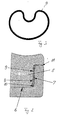
- FIG. 1 shows an executed in particular as a knee joint prosthesis artificial joint 1 in a sectional side view.
- a joint support 4 has a projection 5, which in relation to a recess 6 of the Gelenkplateaus 3 in FIG. 2 Has shown oversize 7.
- a distinct from the body temperature of the patient temperature is first set by heating or cooling of the projection 5 and / or the recess 6 and thereby different thermal expansions are achieved. After insertion of the projection 5 in the recess 6, a temperature compensation takes place, whereby the projection 5 is braced in the recess 6 and at the same time applies flat.
- the thermal shrinkage connection realized by means of the temperature difference can at the same time also be advantageously used to increase the load capacity of the joint 1 by means of the fixing forces introduced in this way and the stresses generated thereby.
- the voltages are set in an optimal manner so that they counteract the load-induced force. For example, can be generated in this way, a stress state in which the joint support 4 is only loaded by compressive forces, however, the action of tensile forces due to the bias is excluded.
- FIG. 2 shown in detail
- FIG. 1 a detailed representation of the in FIG. 1 shown artificial joint 1 shows. Shown is the ready-to-use functional position, in which the projection 5 is already inserted positively and positively into the recess 6.
- the original oversize 7 of the projection 5, which is shown only by dashed lines, is first reduced by cooling to a shrinkage dimension 8, which is likewise shown in dashed lines, so that trouble-free mounting is made possible.
- a shrinkage dimension 8 which is likewise shown in dashed lines
- an undercut 10 is formed, which leads in addition to a positive fixing of the projection 5 in the recess 6.
- the region of the undercut 10 relative to an edge region 11 of the recess 6 different voltage excursions are achieved, so that the resulting force component leads to a bias in the direction of the projection 5 relative to the recess 6.
- FIG. 3 additionally shows a plan view of the in FIG. 1 shown joint 1.
- the contact surface 9 has a steady course, through which a uniform introduction of the fixing force over the entire circumference is ensured. As a result, the load capacity of the artificial joint 1 can be further increased.
Landscapes
- Health & Medical Sciences (AREA)
- Orthopedic Medicine & Surgery (AREA)
- Physical Education & Sports Medicine (AREA)
- Cardiology (AREA)
- Oral & Maxillofacial Surgery (AREA)
- Transplantation (AREA)
- Engineering & Computer Science (AREA)
- Biomedical Technology (AREA)
- Heart & Thoracic Surgery (AREA)
- Vascular Medicine (AREA)
- Life Sciences & Earth Sciences (AREA)
- Animal Behavior & Ethology (AREA)
- General Health & Medical Sciences (AREA)
- Public Health (AREA)
- Veterinary Medicine (AREA)
- Prostheses (AREA)
Description
- Die Erfindung betrifft ein künstliches Gelenk mit einem Gelenkplateau und einer Gelenkauflage, die mittels einer durch eine Ausnehmung und einen darin eingesetzten Vorsprung bestimmte Kontaktfläche miteinander verbunden sind, wobei der Vorsprung gegenüber der Ausnehmung bei Körpertemperatur des Patienten ein Übermaß aufweist und mittels einer Temperaturdifferenz des Vorsprunges oder der Ausnehmung gegenüber der Körpertemperatur des Patienten in die Ausnehmung einsetzbar ist. Weiterhin betrifft die Erfindung ein Verfahren zur Herstellung einer Verbindung in einem solchen künstlichen Gelenk.
- Ein solches künstliches Gelenk ist beispielsweise bereits durch die
US 487 8916 bekannt, die den nächsten Stand der Technik darstellt. Das künstliche Gelenk hat ein dabei ein rotationssymmetrisches Gelenkplateau und eine kugelschalenförmige Gelenkauflage, die mittels einer Schrumpfverbindung miteinander verbunden sind. Die Gelenkauflage weist in dem Gelenkplateau bei Körpertemperatur des Patienten ein Übermaß auf und ist daher ausschließlich mittels einer Temperaturdifferenz gegenüber der Körpertemperatur des Patienten in die Ausnehmung einsetzbar. - Gattungsgemäße künstliche Gelenke sind auch durch die
US 58 58 020 sowie dieFR 24 93 139 A1 - Als nachteilig erweist sich bei den bekannten Gelenken der genannten Art, dass die Belastbarkeit des künstlichen Gelenkes nicht dauerhaft sichergestellt werden kann. Insbesondere sind Beschädigungen der Gelenkteile nicht zuverlässig auszuschließen.
- Durch die
EP 04 95 340 A1 ist auch weiterhin bereits ein modularer Bausatz für den Tibiateil einer Kniegelenkprothese bekannt, der aus einem Tibiaplateau mit einem Zapfen und aus einer Gelenkauflage aus Polyethylen besteht. In das Tibiaplateau sind unterschiedlich große Stämme einsetzbar und unterschiedlich hohe Gelenkauflagen sind in einer Ebene des Tibiaplateaus allseitig geführt. Zur Fixierung der Gelenkauflage wird diese in die Ebene des Tibiaplateaus durch eine Schwenkbewegung eingebracht. Als nachteilig hat es sich dabei jedoch erwiesen, dass die dadurch erzielbare Belastbarkeit vergleichsweise gering ist und zudem die so gebildete Schnappverbindung im Gebrauchszustand einen Hohlraum zwischen der Gelenkauflage und dem Tibiaplateau ausspart. - Es ist ferner auch durch die
CH-PS 66 73 83 - Der Erfindung liegt die Aufgabe zugrunde, eine Möglichkeit zu schaffen, eine Kniegelenkprothese der eingangs genannten Art derart auszuführen, dass dadurch die Belastbarkeit insbesondere Dauerbelastbarkeit über einen langen Zeitraum hinweg wesentlich verbessert ist. Weiterhin soll ein Verfahren zur Herstellung einer solchen Kniegelenkprothese geschaffen werden.
- Die erstgenannte Aufgabe wird erfindungsgemäß mit einer Kniegelenkprothese gemäß den Merkmalen des Anspruchs 1 gelöst. Die weitere Ausgestaltung der erfindungsgemäßen Kniegelenkprothese ist den Unteransprüchen 2 bis 15 zu entnehmen.
- Erfindungsgemäß ist also ein künstliches Gelenk vorgesehen, die Kontaktfläche bzw. das Übermaß ortsabhängig unterschiedlich derart bemessen ist, dass aufgrund der auf den Vorsprung wirkenden Fixierkräfte bei Körpertemperatur des Patienten in der Gelenkauflage und/oder Gelenkplateaus ein Spannungszustand realisiert ist, durch den die Belastbarkeit und/oder Haltbarkeit des Gelenkes erhöht ist. Die Erfindung geht dabei von der überraschenden Erkenntnis aus, dass die bei dem künstlichen Gelenk zur Fixierung bestimmte und mittels der Temperaturdifferenz realisierte thermische Schrumpfverbindung zugleich auch in vorteilhafter Weise dazu genutzt werden kann, mittels der auf diese Weise eingebrachten Fixierkräfte und dadurch erzeugten Spannungen die Belastbarkeit des Gelenkes zu erhöhen. Hierzu werden die Spannungen in optimaler Weise derart eingestellt, dass diese der lastbedingten Krafteinwirkung entgegenwirken. Beispielsweise kann auf diese Weise ein mehrdimensionaler Spannungszustand erzeugt werden, bei dem die Gelenkauflage lediglich durch Druckkräfte belastet wird, hingegen die Einwirkung von Zugkräften aufgrund der Vorspannung ausgeschlossen ist.
- Hierzu wird nach einer besonders vorteilhaften Ausführungsform der Erfindung aufgrund der Fixierkräfte ein gezielter Druckzustand in der Gelenkauflage erzeugt, welcher einer äußeren Krafteinwirkung unter Belastung entgegenwirkt.
- Dabei ist es besonders praxisgerecht, wenn die Kontaktfläche derart ausgeführt ist, dass der Spannungszustand oder der Druckzustand hinsichtlich des Betrages und/oder und der Richtung einstellbar ist, um auf diese Weise eine optimale Anpassung des Gelenkes an den Patienten und dessen individuelle Anforderungen erfüllen zu können.
- Dabei erweist sich eine Abwandlung als besonders belastbar, bei welcher der Betrag des aufgrund der Fixierkräfte eingebrachten Druckzustandes größer als der Betrag einer äußeren Krafteinwirkung ist. Hierdurch treten auch bei großen äußeren Krafteinwirkungen in der Gelenkauflage keine Zugkräfte auf. Die Belastbarkeit hinsichtlich äußerer Druckkräfte ist demgegenüber jedoch erhöht, so dass hierdurch eine Erhöhung der Belastbarkeit einhergeht.
- Eine besonders praxisrelevante Gestaltung wird auch dann erreicht, wenn der Druck- bzw. Spannungszustand in Abhängigkeit der Hauptbelastungsebene des künstlichen Gelenkes einstellbar ist. Hierdurch ist es möglich, einen an die Belastung des Gelenkes durch den Patienten angepassten Spannungszustand bereits bei der Fixierung der Gelenkauflage an dem Gelenkplateau zu erreichen. Hierdurch kann aufgrund der auf diese Weise optimierten Anpassung des Gelenkes eine weitere Steigerung der Belastungsgrenzen insbesondere bei an sich bekannten Werkstoffen erreicht werden, ohne zu diesem Zweck die äußeren Abmessungen der Bauelemente ändern zu müssen.
- In besonders vorteilhafter Weise wird erreicht, dass der Spannungszustand durch eine einer äußeren Krafteinwirkung entgegenwirkende Vorspannung gegeben ist.
- Der Spannungszustand könnte bereits herstellerseitig weitgehend vorbestimmt sein. Um jedoch eine Anpassung an den Patienten in besonders vorteilhafter Weise realisieren zu können ist im Bereich der Kontaktfläche ein zur Einstellung des Spannungszustand vorgesehenes Zwischenelemente vorgesehen, durch das der Spannungszustand ortsabhängig variabel eingestellt werden kann.
- Beispielsweise ist hierzu das Element in unterschiedlichen Positionen festlegbar, um so eine einfache Einstellbarkeit durch den Operateur zu ermöglichen.
- Als besonders praxisgerecht erweist sich dabei auch eine Abwandlung bei der das Element als eine Schale ausgeführt ist und eine Festlegung des Gelenkplateaus gegenüber der Gelenkauflage in unterschiedlichen Winkelstellungen gestattet.
- Zu diesem Zweck erweist sich eine Ausgestaltung als besonders vorteilhaft, bei der die Ausnehmung eine den Vorsprung formschlüssig fixierende Hinterschneidung aufweist, die durch eine Kontur oder eine Topographie der Gelenkäuflage, insbesondere der Materialstärke, bestimmt ist, weil dadurch die auftretenden Fixierkräfte in verschiedenen Bereichen unterschiedlich eingestellt werden können. Weiterhin könnten unterschiedliche Übermaße in Abhängigkeit der Funktionsebenen des Gelenkes vorgesehen werden. Es kann also der Spannungszustand in dem Gelenk insbesondere hinsichtlich der erwartungsgemäßen Belastung wesentlich optimiert werden und zugleich die Lebensdauer erhöht werden. Der in die Ausnehmung eingesetzte Vorsprung ist dabei mittels der Schrumpfverbindung kraft- und formschlüssig fixiert. Daher ist auch die Fixierung einer nicht rotationssymmetrischen, beispielsweise nierenförmigen Gelenkauflage uneingeschränkt geeignet. Beispielsweise wird durch eine gegenüber der Fügerichtung geneigte Kontaktfläche eine Vorspannkraft erzeugt, durch die zugleich auch eine Spaltbildung zwischen dem Gelenkplateau und der Gelenkauflage zuverlässig ausgeschlossen werden.
Eine besonders vorteilhafte Ausführungsform der Erfindung, wird auch dann erreicht, wenn das Gelenkplateau und die Gelenkauflage jeweils einen unterschiedlichen Wärmeausdehnungskoeffizienten aufweisen. Hierdurch führt eine gemeinsame Erwärmung oder Abkühlung des Gelenkplateaus zusammen mit der Gelenkauflage zu einer unterschiedlichen Wärmeausdehnung bzw. Kälteschrumpfung, so dass sich ein Differenzmaß einstellt. Es ist daher nicht erforderlich, lediglich die Ausnehmung zu erwärmen und / oder den Vorsprung abzukühlen und in dem so eingestellten Zustand zusammenzufügen. - Dabei erweist es sich als besonders praxisnah, wenn das Gelenkplateau und die Gelenkauflage konturbündig miteinander verbunden sind. Hierdurch können unerwünschte Vorsprünge vermieden und die Belastbarkeit auch über einen langen Zeitraum hinweg wesentlich verbessert werden. Die äußeren Abmessungen, beispielsweise die Querschnittsfläche des Gelenkplateaus und der Gelenkauflage stimmen dabei insbesondere identisch überein.
- Besonders einfach ist hingegen eine Abwandlung der erfindungsgemäßen Kniegelenkprothese, bei der eine Kontaktfläche zwischen dem Vorsprung und der Ausnehmung mit einer die Kraftübertragung verbessernden Oberflächenbeschaffenheit, insbesondere Rauhigkeit oder Strukturierung, ausgestattet ist. Hierdurch kann die Belastbarkeit der Verbindung durch eine verbesserte Haftreibung deutlich erhöht werden. Die Kontaktfläche ist hierzu beispielsweise mit einer Strukturierung ausgestattet.
- Als besonders praxisgerecht erweist sich dabei auch eine Ausgestaltung der Erfindung, bei welcher der Gelenkauflage ein Vorsprung aus Polyethylen und dem Gelenkplateau eine Ausnehmung aus einem Metall zugeordnet ist. Hierdurch wird ein optimales Verhältnis der Wärmedehnungskoeffizienten erreicht, so dass bereits eine Temperaturdifferenz von ca. 10°C zu einer Dehnungsdifferenz von ca. 0,1 mm führt. Die Handhabung des Gelenkplateaus und der Gelenkauflage zur Montage wird dadurch erleichtert und gestattet daher eine entsprechend der jeweiligen individuellen Anforderungen des Patienten vorzunehmende Auswahl der geeigneten Gelenkauflage während der Behandlung.
- Weiterhin hat es sich als besonders zweckmäßig erwiesen, wenn der Vorsprung und die Ausnehmung an einer umlaufende Kontaktfläche gegeneinander liegen, die einen stetigen Verlauf hat. Hierdurch wird eine gleichmäßige Krafteinleitung über die gesamte Länge der Kontaktfläche realisiert, wodurch die Belastbarkeit der Verbindung weiter verbessert werden kann. Dabei weist nach einer weiteren besonders günstigen Abwandlung der vorliegenden Erfindung das Gelenkplateau die Ausnehmung und die Gelenkauflage den Vorsprung auf.
- Die zweitgenannte Aufgabe, ein Verfahren zur Herstellung eines insbesondere als Kniegelenkprothese ausgeführten künstlichen Gelenks zu schaffen, bei dem ein Gelenkplateau mit einer Gelenkauflage mittels einer durch eine Ausnehmung und einen darin eingesetzten Vorsprung gebildeten Kontaktfläche verbunden wird, wird erfindungsgemäß dadurch gelöst, dass die Kontaktfläche bzw. das Übermaß ortsabhängig unterschiedlich derart bemessen werden, dass aufgrund der auf den Vorsprung wirkenden Fixierkräfte bei Körpertemperatur des Patienten in der Gelenkauflage'*ein Spannungszustand erzeugt wird, durch den die Belastbarkeit und/oder Haltbarkeit erhöht ist. Hierdurch wird eine in einfacher Weise zu handhabende Fixierung zwischen dem Gelenkplateau und der Gelenkauflage realisiert, die eine wesentlich höhere Belastbarkeit aufgrund des durch die Schrumpfverbindung eingebrachten Spannungszustandes gestattet.
- Die Erfindung lässt verschiedene Ausführungsformen zu. Zur weiteren Verdeutlichung ihres Grundprinzips ist eine davon in der Zeichnung dargestellt und wird nachfolgend beschrieben. Diese zeigt in
- Fig.1
- eine geschnittene Seitenansicht eines erfindungsgemäßen künstlichen Gelenks;
- Fig.2
- eine Detaildarstellung des in
Figur 1 gezeigten künstlichen Gelenks; - Fig.3
- eine Draufsicht auf das in
Figur 1 gezeigte Gelenk. -
Figur 1 zeigt ein insbesondere als Kniegelenkprothese ausgeführtes künstliches Gelenk 1 in einer geschnittenen Seitenansicht. Zu erkennen ist ein mit einem Zapfen 2 ausgestattetes Gelenkplateau 3, das mit einer Gelenkauflage 4 kraft- und formschlüssig verbunden ist. Hierzu hat die Gelenkauflage 4 einen Vorsprung 5, welcher gegenüber einer Ausnehmung 6 des Gelenkplateaus 3 ein inFigur 2 näher dargestelltes Übermaß 7 aufweist. Um den Vorsprung 5 in die Ausnehmung 6 einsetzen zu können, wird zunächst eine von der Körpertemperatur des Patienten deutlich abweichende Temperatur durch Erwärmung bzw. Abkühlung des Vorsprunges 5 und / oder der Ausnehmung 6 eingestellt und dadurch werden jeweils unterschiedliche thermische Dehnungen erreicht. Nach dem Einsetzen des Vorsprunges 5 in die Ausnehmung 6 erfolgt ein Temperaturausgleich, wodurch sich der Vorsprung 5 in der Ausnehmung 6 verspannt und zugleich flächig anlegt. Die mittels der Temperaturdifferenz realisierte thermische Schrumpfverbindung kann zugleich auch in vorteilhafter Weise dazu genutzt werden, mittels der auf diese Weise eingebrachten Fixierkräfte und dadurch erzeugten Spannungen die Belastbarkeit des Gelenkes 1 zu erhöhen. Hierzu werden die Spannungen in optimaler Weise derart eingestellt, dass diese der lastbedingten Krafteinwirkung entgegenwirken. Beispielsweise kann auf diese Weise ein Spannungszustand erzeugt werden, bei dem die Gelenkauflage 4 lediglich durch Druckkräfte belastet wird, hingegen die Einwirkung von Zugkräften aufgrund der Vorspannung ausgeschlossen ist. - Die genaue Formgebung des Vorsprungs 5 und der Ausnehmung 6 wird anhand der
Figur 2 näher dargestellt, die eine Detaildarstellung des inFigur 1 gezeigten künstlichen Gelenks 1 zeigt. Dargestellt ist die gebrauchsbereite Funktionsstellung, in welcher der Vorsprung 5 bereits kraft- und formschlüssig in die Ausnehmung 6 eingesetzt ist. Das ursprüngliche, lediglich gestrichelt dargestellte Übermaß 7 des Vorsprunges 5 wird durch Abkühlung zunächst auf ein ebenfalls gestrichelt dargestelltes Schrumpfmaß 8 reduziert, so dass eine problemlose Montage ermöglicht wird. Bei dem nachfolgenden Temperaturausgleich wird der Vorsprung 5 flächig gegen die Ausnehmung 6 angepresst und dort kraftschlüssig fixiert. Bedingt durch eine geneigte Anordnung einer Kontaktfläche 9 der Ausnehmung 6 ist eine Hinterschneidung 10 gebildet, die zusätzlich zu einer formschlüssigen Fixierung des Vorsprungs 5 in der Ausnehmung 6 führt. Zugleich werden dadurch im Bereich der Hinterschneidung 10 gegenüber einem Randbereich 11 der Ausnehmung 6 voneinander abweichende Spannungsvertäufe erreicht, so dass die resultierende Kraftkomponente zu einer Vorspannung in Richtung des Vorsprunges 5 gegenüber der Ausnehmung 6 führt. -
Figur 3 zeigt ergänzend eine Draufsicht auf das inFigur 1 gezeigte Gelenk 1. Zu erkennen ist die umlaufende Kontaktfläche 9 zwischen dem in denFiguren 1 und2 dargestellten Vorsprung 5 und der Ausnehmung 6. Die Kontaktfläche 9 weist dabei einen stetigen Verlauf auf, durch den eine gleichmäßige Einleitung der Fixierkraft über den gesamten Umfang sichergestellt ist. Hierdurch kann die Belastbarkeit des künstlichen Gelenks 1 weiter gesteigert werden.
Claims (16)
- Ein künstliches Gelenk (1) mit einem Gelenkplateau (3) und einer Gelenkauflage (4), die mittels einer durch eine Ausnehmung (6) und einen darin eingesetzten Vorsprung (5) bestimmte Kontaktfläche (9) miteinander verbunden sind, wobei der Vorsprung (5) gegenüber der Ausnehmung (6) bei Körpertemperatur des Patienten ein Übermaß (7) aufweist und mittels einer Temperaturdifferenz des Vorsprunges (5) und/oder der Ausnehmung (6) gegenüber der Körpertemperatur des Patienten in die Ausnehmung (6) einsetzbar ist, dadurch gekennzeichnet, dass die Kontaktfläche (9) bzw. das Übermaß (7) ortsabhängig unterschiedlich derart bemessen ist, dass aufgrund der auf den Vorsprung (5) wirkenden Fixierkräfte bei Körpertemperatur des Patienten in der Gelenkauflage (4) und/oder Gelenkplateaus (3) ein Spannungszustand realisiert ist, durch den die Belastbarkeit und/oder Haltbarkeit des künstlichen Gelenks (1) erhöht ist.
- Künstliches Gelenk (1) nach Anspruch 1, dadurch gekennzeichnet, dass aufgrund der Fixierkräfte ein gezielter Druckzustand in der Gelenkauflage (4) einstellbar ist.
- Künstliches Gelenk (1) nach den Ansprüchen 1 oder 2, dadurch gekennzeichnet, dass die Kontaktfläche (9) derart ausgeführt ist, dass der Spannungszustand oder der Druckzustand hinsichtlich des Betrages und/oder und der Richtung einstellbar ist.
- Künstliches Gelenk (1) nach zumindest einem der vorhergehenden Ansprüche, dadurch gekennzeichnet, dass der Betrag des aufgrund der Fixierkräfte eingebrachten Spannungszustandes oder Druckzustandes größer als der Betrag einer äußeren Krafteinwirkung ist.
- Künstliches Gelenk (1) nach zumindest einem der vorhergehenden Ansprüche, dadurch gekennzeichnet, dass der Druck- bzw. Spannungszustand in Abhängigkeit der Hauptbelastungsebene des künstlichen Gelenkes (1) einstellbar ist.
- Künstliches Gelenk (1) nach zumindest einem der vorhergehenden Ansprüche, dadurch gekennzeichnet, dass der Spannungszustand durch eine einer äußeren Krafteinwirkung entgegenwirkende Vorspannung gegeben ist.
- Künstliches Gelenk (1) nach zumindest einem der vorhergehenden Ansprüche, dadurch gekennzeichnet, dass im Bereich der Kontaktfläche ein zur Einstellung des Spannungszustandes vorgesehenes Zwischenelement vorgesehen ist.
- Künstliches Gelenk (1) nach Anspruch 6, dadurch gekennzeichnet, dass das Zwischenelement in unterschiedlichen Positionen festlegbar ist.
- Künstliches Gelenk (1) nach Anspruch 6 oder 7, dadurch gekennzeichnet, dass das Zwischenelement als eine Schale ausgeführt ist.
- Künstliches Gelenk (1) nach zumindest einem der vorhergehenden Ansprüche, dadurch gekennzeichnet, dass die Ausnehmung (6) eine den Vorsprung (5) formschlüssig fixierende Hinterschneidung (10) aufweist, die durch eine Kontur oder eine Topographie der Gelenkauflage (4), insbesondere der Materialstärke, bestimmt ist.
- Künstliches Gelenk (1) nach zumindest einem der vorhergehenden Ansprüche, dadurch gekennzeichnet, dass eine das Gelenkplateau (3) und die Gelenkauflage (4) jeweils einen unterschiedlichen Wärmeausdehnungskoeffizienten aufweisen.
- Künstliches Gelenk (1) nach zumindest einem der vorhergehenden Ansprüche, dadurch gekennzeichnet, dass eine das Gelenkplateau (3) und die Gelenkauflage (4) konturbündig miteinander verbunden sind.
- Künstliches Gelenk (1) nach zumindest einem der vorhergehenden Ansprüche, dadurch gekennzeichnet, dass eine Kontaktfläche (9) zwischen dem Vorsprung (5) und der Ausnehmung (6) mit einer die Kraftübertragung verbessernden Oberflächenbeschaffenheit, insbesondere Rauhigkeit oder Strukturierung, ausgestattet ist.
- Künstliches Gelenk (1) nach zumindest einem der vorhergehenden Ansprüche, dadurch gekennzeichnet, dass der Gelenkauflage (4) ein Vorsprung (5) aus Polyethylen und dem Gelenkplateau aus einem Metall (3) eine Ausnehmung (6) zugeordnet ist.
- Künstliches Gelenk (1) nach zumindest einem der vorhergehenden Ansprüche, dadurch gekennzeichnet, dass der Vorsprung (5) und die Ausnehmung (6) an einer umlaufenden Kontaktfläche (9) gegeneinander liegen, die einen stetigen Verlauf hat.
- Verfahren zum Verbinden eines Gelenkplateau mit einer Gelenkauflage eines künstlichen Gelenks nach Anspruch 1, bei dem das Gelenkplateau mit der Gelenkauflage mittels einer durch eine Ausnehmung und einen darin eingesetzten Vorsprung gebildeten Kontaktfläche verbunden wird, wobei zunächst mittels einer Temperaturdifferenz gegenüber der Körpertemperatur des Patienten eine unterschiedliche Wärmedehnung und / oder Schrumpfung zwischen dem Vorsprung und der Ausnehmung erreicht und anschließend der Vorsprung in die Ausnehmung eingesetzt wird, dadurch gekennzeichnet, dass die Kontaktfläche bzw. das Übermaß ortsabhängig unterschiedlich derart bemessen werden, dass aufgrund der auf den Vorsprung wirkenden Fixierkräfte bei Körpertemperatur des Patienten in der Gelenkauflage ein Spannungszustand erzeugt wird, durch den die Belastbarkeit und/oder Haltbarkeit erhöht ist.
Applications Claiming Priority (3)
| Application Number | Priority Date | Filing Date | Title |
|---|---|---|---|
| DE10257774A DE10257774A1 (de) | 2002-12-10 | 2002-12-10 | Künstliches Gelenk |
| DE10257774 | 2002-12-10 | ||
| PCT/DE2003/004025 WO2004052244A1 (de) | 2002-12-10 | 2003-12-09 | Künstliches gelenk |
Publications (2)
| Publication Number | Publication Date |
|---|---|
| EP1575455A1 EP1575455A1 (de) | 2005-09-21 |
| EP1575455B1 true EP1575455B1 (de) | 2008-02-20 |
Family
ID=32477540
Family Applications (1)
| Application Number | Title | Priority Date | Filing Date |
|---|---|---|---|
| EP03782141A Expired - Lifetime EP1575455B1 (de) | 2002-12-10 | 2003-12-09 | Künstliches gelenk |
Country Status (7)
| Country | Link |
|---|---|
| US (1) | US20060206210A1 (de) |
| EP (1) | EP1575455B1 (de) |
| AT (1) | ATE386481T1 (de) |
| AU (1) | AU2003289825A1 (de) |
| DE (2) | DE10257774A1 (de) |
| ES (1) | ES2302963T3 (de) |
| WO (1) | WO2004052244A1 (de) |
Families Citing this family (11)
| Publication number | Priority date | Publication date | Assignee | Title |
|---|---|---|---|---|
| US20020120340A1 (en) | 2001-02-23 | 2002-08-29 | Metzger Robert G. | Knee joint prosthesis |
| US7497874B1 (en) | 2001-02-23 | 2009-03-03 | Biomet Manufacturing Corp. | Knee joint prosthesis |
| US8187280B2 (en) | 2007-10-10 | 2012-05-29 | Biomet Manufacturing Corp. | Knee joint prosthesis system and method for implantation |
| US8328873B2 (en) | 2007-01-10 | 2012-12-11 | Biomet Manufacturing Corp. | Knee joint prosthesis system and method for implantation |
| US8562616B2 (en) | 2007-10-10 | 2013-10-22 | Biomet Manufacturing, Llc | Knee joint prosthesis system and method for implantation |
| JP5448842B2 (ja) | 2007-01-10 | 2014-03-19 | バイオメト マニファクチャリング コーポレイション | 膝関節プロテーゼシステムおよび埋込み方法 |
| US8163028B2 (en) | 2007-01-10 | 2012-04-24 | Biomet Manufacturing Corp. | Knee joint prosthesis system and method for implantation |
| DE102019100016A1 (de) * | 2019-01-02 | 2020-07-02 | Aesculap Ag | Fügeverfahren für eine medizintechnische Vorrichtung |
| JP7589961B2 (ja) * | 2020-05-12 | 2024-11-26 | 泉工医科工業株式会社 | 医療用組立体の製造方法 |
| CN117120003A (zh) * | 2020-12-16 | 2023-11-24 | 孚美公司 | 用于将医用植入物固接在患者体内的固定组件 |
| CN114732571B (zh) * | 2022-06-10 | 2022-10-14 | 北京爱康宜诚医疗器材有限公司 | 膝关节假体的锁夹及膝关节假体 |
Family Cites Families (8)
| Publication number | Priority date | Publication date | Assignee | Title |
|---|---|---|---|---|
| FR2493139B1 (fr) * | 1980-06-30 | 1986-02-14 | Tornier Sa | Prothese totale de hanche perfectionnee |
| CH667383A5 (de) * | 1985-09-12 | 1988-10-14 | Sulzer Ag | Tibiateil fuer eine kniegelenkprothese. |
| FR2595562B1 (fr) * | 1986-03-13 | 1992-08-28 | Rhenter Jean Luc | Cupule de prothese |
| GB9005496D0 (en) * | 1990-03-12 | 1990-05-09 | Howmedica | Tibial component for a replacement knee prosthesis and total knee prosthesis incorporating such a component |
| EP0495340A1 (de) * | 1991-01-18 | 1992-07-22 | Gebrüder Sulzer Aktiengesellschaft | Modularer Bausatz für den Tibiateil einer Kniegelenkprothese |
| WO1995022944A1 (en) * | 1994-02-25 | 1995-08-31 | Intermedics Orthopedics, Inc. | Acetabular cup composite insert and assembly method |
| US5858020A (en) * | 1995-12-05 | 1999-01-12 | Metagen, Llc | Modular prosthesis |
| US6569202B2 (en) * | 2001-04-02 | 2003-05-27 | Whiteside Biomechanics, Inc. | Tray and liner for joint replacement system |
-
2002
- 2002-12-10 DE DE10257774A patent/DE10257774A1/de not_active Ceased
-
2003
- 2003-12-09 WO PCT/DE2003/004025 patent/WO2004052244A1/de not_active Ceased
- 2003-12-09 AT AT03782141T patent/ATE386481T1/de active
- 2003-12-09 US US10/537,969 patent/US20060206210A1/en not_active Abandoned
- 2003-12-09 EP EP03782141A patent/EP1575455B1/de not_active Expired - Lifetime
- 2003-12-09 AU AU2003289825A patent/AU2003289825A1/en not_active Abandoned
- 2003-12-09 DE DE50309222T patent/DE50309222D1/de not_active Expired - Lifetime
- 2003-12-09 ES ES03782141T patent/ES2302963T3/es not_active Expired - Lifetime
Also Published As
| Publication number | Publication date |
|---|---|
| ES2302963T3 (es) | 2008-08-01 |
| ATE386481T1 (de) | 2008-03-15 |
| EP1575455A1 (de) | 2005-09-21 |
| US20060206210A1 (en) | 2006-09-14 |
| WO2004052244A1 (de) | 2004-06-24 |
| DE50309222D1 (de) | 2008-04-03 |
| DE10257774A1 (de) | 2004-07-29 |
| AU2003289825A1 (en) | 2004-06-30 |
Similar Documents
| Publication | Publication Date | Title |
|---|---|---|
| DE69616873T2 (de) | Überbrückungsvorrichtung für Gelenkprothese | |
| DE69132111T2 (de) | Orthopädisches implantat aus einem metall/verbund-hybrid | |
| DE60110108T2 (de) | Eine orthopädische gelenkprothese | |
| EP0445068B1 (de) | Künstliche Hüftgelenkspfanne | |
| EP1575455B1 (de) | Künstliches gelenk | |
| DE69303385T2 (de) | Femurkomponente für Hüftgelenkersatz | |
| DE60033876T2 (de) | Modularer tibialer Einsatz für ein prosthetisches System | |
| DE69917157T2 (de) | Körpernahe hohle Prothese | |
| DE60111703T2 (de) | Modulare hüftprothese | |
| EP0826347B1 (de) | Gelenkprothese | |
| DE69131625T2 (de) | Prothese mit porösen überzug | |
| DE69001139T2 (de) | Hueftgelenkspfanne mit zwei radien. | |
| DE10109804C2 (de) | Gelenkprothese | |
| EP0442330B1 (de) | Kniegelenk-Endoprothese | |
| DE2849588A1 (de) | Gelenkprothese | |
| EP1250898A1 (de) | Sytem von Bandscheibenprothesen | |
| EP0024442A1 (de) | Verbund-Endoprothese aus einem Metallschaft und einem keramischen Gelenkteil | |
| WO2007068440A1 (de) | Endoprothese mit zwischenteil | |
| EP1827319B1 (de) | Künstliches gelenkelement sowie ein damit ausgestattetes greifwerkzeug | |
| WO2006128509A1 (de) | Bandscheibenimplantat | |
| EP3714840A1 (de) | Hüftpfanne einer hüftgelenk-endoprothese | |
| DE4138609C2 (de) | Kugelhülsen-Zentralgelenk | |
| DE19548075C2 (de) | Beinprothese | |
| EP1114624A1 (de) | Stossabsorbierende Gelenkpfanne | |
| DE102004027659B4 (de) | Hüftgelenk-Endoprothese |
Legal Events
| Date | Code | Title | Description |
|---|---|---|---|
| PUAI | Public reference made under article 153(3) epc to a published international application that has entered the european phase |
Free format text: ORIGINAL CODE: 0009012 |
|
| 17P | Request for examination filed |
Effective date: 20050711 |
|
| AK | Designated contracting states |
Kind code of ref document: A1 Designated state(s): AT BE BG CH CY CZ DE DK EE ES FI FR GB GR HU IE IT LI LU MC NL PT RO SE SI SK TR |
|
| AX | Request for extension of the european patent |
Extension state: AL LT LV MK |
|
| DAX | Request for extension of the european patent (deleted) | ||
| GRAP | Despatch of communication of intention to grant a patent |
Free format text: ORIGINAL CODE: EPIDOSNIGR1 |
|
| GRAS | Grant fee paid |
Free format text: ORIGINAL CODE: EPIDOSNIGR3 |
|
| GRAA | (expected) grant |
Free format text: ORIGINAL CODE: 0009210 |
|
| AK | Designated contracting states |
Kind code of ref document: B1 Designated state(s): AT BE BG CH CY CZ DE DK EE ES FI FR GB GR HU IE IT LI LU MC NL PT RO SE SI SK TR |
|
| REG | Reference to a national code |
Ref country code: GB Ref legal event code: FG4D Free format text: NOT ENGLISH |
|
| REG | Reference to a national code |
Ref country code: CH Ref legal event code: EP |
|
| REG | Reference to a national code |
Ref country code: IE Ref legal event code: FG4D Free format text: LANGUAGE OF EP DOCUMENT: GERMAN |
|
| REF | Corresponds to: |
Ref document number: 50309222 Country of ref document: DE Date of ref document: 20080403 Kind code of ref document: P |
|
| REG | Reference to a national code |
Ref country code: CH Ref legal event code: NV Representative=s name: TROESCH SCHEIDEGGER WERNER AG |
|
| GBT | Gb: translation of ep patent filed (gb section 77(6)(a)/1977) |
Effective date: 20080429 |
|
| PG25 | Lapsed in a contracting state [announced via postgrant information from national office to epo] |
Ref country code: FI Free format text: LAPSE BECAUSE OF FAILURE TO SUBMIT A TRANSLATION OF THE DESCRIPTION OR TO PAY THE FEE WITHIN THE PRESCRIBED TIME-LIMIT Effective date: 20080220 |
|
| REG | Reference to a national code |
Ref country code: ES Ref legal event code: FG2A Ref document number: 2302963 Country of ref document: ES Kind code of ref document: T3 |
|
| PG25 | Lapsed in a contracting state [announced via postgrant information from national office to epo] |
Ref country code: SI Free format text: LAPSE BECAUSE OF FAILURE TO SUBMIT A TRANSLATION OF THE DESCRIPTION OR TO PAY THE FEE WITHIN THE PRESCRIBED TIME-LIMIT Effective date: 20080220 |
|
| REG | Reference to a national code |
Ref country code: IE Ref legal event code: FD4D |
|
| PG25 | Lapsed in a contracting state [announced via postgrant information from national office to epo] |
Ref country code: SE Free format text: LAPSE BECAUSE OF FAILURE TO SUBMIT A TRANSLATION OF THE DESCRIPTION OR TO PAY THE FEE WITHIN THE PRESCRIBED TIME-LIMIT Effective date: 20080520 Ref country code: SK Free format text: LAPSE BECAUSE OF FAILURE TO SUBMIT A TRANSLATION OF THE DESCRIPTION OR TO PAY THE FEE WITHIN THE PRESCRIBED TIME-LIMIT Effective date: 20080220 Ref country code: CZ Free format text: LAPSE BECAUSE OF FAILURE TO SUBMIT A TRANSLATION OF THE DESCRIPTION OR TO PAY THE FEE WITHIN THE PRESCRIBED TIME-LIMIT Effective date: 20080220 Ref country code: PT Free format text: LAPSE BECAUSE OF FAILURE TO SUBMIT A TRANSLATION OF THE DESCRIPTION OR TO PAY THE FEE WITHIN THE PRESCRIBED TIME-LIMIT Effective date: 20080721 Ref country code: IE Free format text: LAPSE BECAUSE OF FAILURE TO SUBMIT A TRANSLATION OF THE DESCRIPTION OR TO PAY THE FEE WITHIN THE PRESCRIBED TIME-LIMIT Effective date: 20080220 Ref country code: DK Free format text: LAPSE BECAUSE OF FAILURE TO SUBMIT A TRANSLATION OF THE DESCRIPTION OR TO PAY THE FEE WITHIN THE PRESCRIBED TIME-LIMIT Effective date: 20080220 |
|
| ET | Fr: translation filed | ||
| PG25 | Lapsed in a contracting state [announced via postgrant information from national office to epo] |
Ref country code: RO Free format text: LAPSE BECAUSE OF FAILURE TO SUBMIT A TRANSLATION OF THE DESCRIPTION OR TO PAY THE FEE WITHIN THE PRESCRIBED TIME-LIMIT Effective date: 20080220 |
|
| PLBE | No opposition filed within time limit |
Free format text: ORIGINAL CODE: 0009261 |
|
| STAA | Information on the status of an ep patent application or granted ep patent |
Free format text: STATUS: NO OPPOSITION FILED WITHIN TIME LIMIT |
|
| 26N | No opposition filed |
Effective date: 20081121 |
|
| PG25 | Lapsed in a contracting state [announced via postgrant information from national office to epo] |
Ref country code: EE Free format text: LAPSE BECAUSE OF FAILURE TO SUBMIT A TRANSLATION OF THE DESCRIPTION OR TO PAY THE FEE WITHIN THE PRESCRIBED TIME-LIMIT Effective date: 20080220 Ref country code: BG Free format text: LAPSE BECAUSE OF FAILURE TO SUBMIT A TRANSLATION OF THE DESCRIPTION OR TO PAY THE FEE WITHIN THE PRESCRIBED TIME-LIMIT Effective date: 20080520 |
|
| BERE | Be: lapsed |
Owner name: HJS GELENK SYSTEM G.M.B.H. Effective date: 20081231 |
|
| PG25 | Lapsed in a contracting state [announced via postgrant information from national office to epo] |
Ref country code: CY Free format text: LAPSE BECAUSE OF FAILURE TO SUBMIT A TRANSLATION OF THE DESCRIPTION OR TO PAY THE FEE WITHIN THE PRESCRIBED TIME-LIMIT Effective date: 20080220 Ref country code: MC Free format text: LAPSE BECAUSE OF NON-PAYMENT OF DUE FEES Effective date: 20081231 |
|
| PG25 | Lapsed in a contracting state [announced via postgrant information from national office to epo] |
Ref country code: BE Free format text: LAPSE BECAUSE OF NON-PAYMENT OF DUE FEES Effective date: 20081231 |
|
| PG25 | Lapsed in a contracting state [announced via postgrant information from national office to epo] |
Ref country code: LU Free format text: LAPSE BECAUSE OF NON-PAYMENT OF DUE FEES Effective date: 20081209 Ref country code: HU Free format text: LAPSE BECAUSE OF FAILURE TO SUBMIT A TRANSLATION OF THE DESCRIPTION OR TO PAY THE FEE WITHIN THE PRESCRIBED TIME-LIMIT Effective date: 20080821 |
|
| PG25 | Lapsed in a contracting state [announced via postgrant information from national office to epo] |
Ref country code: TR Free format text: LAPSE BECAUSE OF FAILURE TO SUBMIT A TRANSLATION OF THE DESCRIPTION OR TO PAY THE FEE WITHIN THE PRESCRIBED TIME-LIMIT Effective date: 20080220 |
|
| PG25 | Lapsed in a contracting state [announced via postgrant information from national office to epo] |
Ref country code: GR Free format text: LAPSE BECAUSE OF FAILURE TO SUBMIT A TRANSLATION OF THE DESCRIPTION OR TO PAY THE FEE WITHIN THE PRESCRIBED TIME-LIMIT Effective date: 20080521 |
|
| PGFP | Annual fee paid to national office [announced via postgrant information from national office to epo] |
Ref country code: AT Payment date: 20101220 Year of fee payment: 8 Ref country code: FR Payment date: 20110107 Year of fee payment: 8 |
|
| PGFP | Annual fee paid to national office [announced via postgrant information from national office to epo] |
Ref country code: CH Payment date: 20101223 Year of fee payment: 8 |
|
| PGFP | Annual fee paid to national office [announced via postgrant information from national office to epo] |
Ref country code: GB Payment date: 20101221 Year of fee payment: 8 |
|
| PGFP | Annual fee paid to national office [announced via postgrant information from national office to epo] |
Ref country code: IT Payment date: 20101228 Year of fee payment: 8 Ref country code: NL Payment date: 20110208 Year of fee payment: 8 Ref country code: DE Payment date: 20101231 Year of fee payment: 8 |
|
| PGFP | Annual fee paid to national office [announced via postgrant information from national office to epo] |
Ref country code: ES Payment date: 20101222 Year of fee payment: 8 |
|
| REG | Reference to a national code |
Ref country code: DE Ref legal event code: R082 Ref document number: 50309222 Country of ref document: DE Representative=s name: PETER RIEBLING, DE |
|
| REG | Reference to a national code |
Ref country code: DE Ref legal event code: R082 Ref document number: 50309222 Country of ref document: DE Representative=s name: PETER RIEBLING, DE |
|
| REG | Reference to a national code |
Ref country code: NL Ref legal event code: TD Effective date: 20120508 Ref country code: NL Ref legal event code: SD Effective date: 20120508 |
|
| REG | Reference to a national code |
Ref country code: DE Ref legal event code: R082 Ref document number: 50309222 Country of ref document: DE Representative=s name: PETER RIEBLING, DE Effective date: 20120403 Ref country code: DE Ref legal event code: R082 Ref document number: 50309222 Country of ref document: DE Representative=s name: PETER RIEBLING, DE Effective date: 20120418 Ref country code: DE Ref legal event code: R082 Ref document number: 50309222 Country of ref document: DE Representative=s name: PETER RIEBLING, DE Effective date: 20111222 Ref country code: DE Ref legal event code: R081 Ref document number: 50309222 Country of ref document: DE Owner name: LIMACORPORATE SPA, IT Free format text: FORMER OWNER: AEQUOS ENDOPROTHETIK GMBH, 82166 GRAEFELFING, DE Effective date: 20120418 Ref country code: DE Ref legal event code: R081 Ref document number: 50309222 Country of ref document: DE Owner name: LIMACORPORATE SPA, IT Free format text: FORMER OWNER: HJS GELENK SYSTEM GMBH, 81925 MUENCHEN, DE Effective date: 20120403 Ref country code: DE Ref legal event code: R082 Ref document number: 50309222 Country of ref document: DE Representative=s name: RIEBLING, PETER, DIPL.-ING. DR.-ING., DE Effective date: 20120403 Ref country code: DE Ref legal event code: R082 Ref document number: 50309222 Country of ref document: DE Representative=s name: RIEBLING, PETER, DIPL.-ING. DR.-ING., DE Effective date: 20111222 Ref country code: DE Ref legal event code: R082 Ref document number: 50309222 Country of ref document: DE Representative=s name: RIEBLING, PETER, DIPL.-ING. DR.-ING., DE Effective date: 20120418 Ref country code: DE Ref legal event code: R081 Ref document number: 50309222 Country of ref document: DE Owner name: LIMACORPORATE SPA, SAN DANIELE DEL FRIULI, IT Free format text: FORMER OWNER: HJS GELENK SYSTEM GMBH, 81925 MUENCHEN, DE Effective date: 20120403 Ref country code: DE Ref legal event code: R081 Ref document number: 50309222 Country of ref document: DE Owner name: LIMACORPORATE SPA, SAN DANIELE DEL FRIULI, IT Free format text: FORMER OWNER: AEQUOS ENDOPROTHETIK GMBH, 82166 GRAEFELFING, DE Effective date: 20120418 |
|
| REG | Reference to a national code |
Ref country code: ES Ref legal event code: PC2A Owner name: LIMACORPORATE SPA Effective date: 20120611 |
|
| REG | Reference to a national code |
Ref country code: CH Ref legal event code: PUE Owner name: LIMACORPORATE SPA Free format text: AEQUOS ENDOPROTHETIK GMBH#AM HAAG 10#82166 GRAEFELFING (DE) -TRANSFER TO- LIMACORPORATE SPA#VIA NAZIONALE 52 FRAZIONE VILLANOVA#33038 SAN DANIELE DEL FRIULI (UD) (IT) Ref country code: CH Ref legal event code: PFA Owner name: AEQUOS ENDOPROTHETIK GMBH Free format text: HJS GELENK SYSTEM GMBH#MAUERKIRCHERSTRASSE 180#81925 MUENCHEN (DE) -TRANSFER TO- AEQUOS ENDOPROTHETIK GMBH#AM HAAG 10#82166 GRAEFELFING (DE) Ref country code: CH Ref legal event code: NV Representative=s name: R. A. EGLI & CO. PATENTANWAELTE |
|
| REG | Reference to a national code |
Ref country code: NL Ref legal event code: V1 Effective date: 20120701 Ref country code: GB Ref legal event code: 732E Free format text: REGISTERED BETWEEN 20120614 AND 20120620 |
|
| REG | Reference to a national code |
Ref country code: CH Ref legal event code: PL |
|
| REG | Reference to a national code |
Owner name: LIMACORPORATE S.P.A., IT Effective date: 20120703 Ref country code: FR Ref legal event code: TP Ref country code: FR Ref legal event code: CD Owner name: LIMACORPORATE S.P.A., IT Effective date: 20120703 Effective date: 20120703 Ref country code: FR Ref legal event code: CA |
|
| GBPC | Gb: european patent ceased through non-payment of renewal fee |
Effective date: 20111209 |
|
| REG | Reference to a national code |
Ref country code: FR Ref legal event code: ST Effective date: 20120831 |
|
| REG | Reference to a national code |
Ref country code: DE Ref legal event code: R119 Ref document number: 50309222 Country of ref document: DE Effective date: 20120703 |
|
| PG25 | Lapsed in a contracting state [announced via postgrant information from national office to epo] |
Ref country code: DE Free format text: LAPSE BECAUSE OF NON-PAYMENT OF DUE FEES Effective date: 20120703 Ref country code: LI Free format text: LAPSE BECAUSE OF NON-PAYMENT OF DUE FEES Effective date: 20111231 Ref country code: GB Free format text: LAPSE BECAUSE OF NON-PAYMENT OF DUE FEES Effective date: 20111209 Ref country code: CH Free format text: LAPSE BECAUSE OF NON-PAYMENT OF DUE FEES Effective date: 20111231 |
|
| PG25 | Lapsed in a contracting state [announced via postgrant information from national office to epo] |
Ref country code: IT Free format text: LAPSE BECAUSE OF NON-PAYMENT OF DUE FEES Effective date: 20111209 |
|
| REG | Reference to a national code |
Ref country code: AT Ref legal event code: MM01 Ref document number: 386481 Country of ref document: AT Kind code of ref document: T Effective date: 20111209 |
|
| PG25 | Lapsed in a contracting state [announced via postgrant information from national office to epo] |
Ref country code: AT Free format text: LAPSE BECAUSE OF NON-PAYMENT OF DUE FEES Effective date: 20111209 Ref country code: NL Free format text: LAPSE BECAUSE OF NON-PAYMENT OF DUE FEES Effective date: 20120701 |
|
| PG25 | Lapsed in a contracting state [announced via postgrant information from national office to epo] |
Ref country code: FR Free format text: LAPSE BECAUSE OF NON-PAYMENT OF DUE FEES Effective date: 20120102 |
|
| REG | Reference to a national code |
Ref country code: ES Ref legal event code: FD2A Effective date: 20130703 |
|
| PG25 | Lapsed in a contracting state [announced via postgrant information from national office to epo] |
Ref country code: ES Free format text: LAPSE BECAUSE OF NON-PAYMENT OF DUE FEES Effective date: 20111210 |