EP1575435B1 - Systeme de thermokeratoplastie a electro-induction - Google Patents
Systeme de thermokeratoplastie a electro-induction Download PDFInfo
- Publication number
- EP1575435B1 EP1575435B1 EP20030796799 EP03796799A EP1575435B1 EP 1575435 B1 EP1575435 B1 EP 1575435B1 EP 20030796799 EP20030796799 EP 20030796799 EP 03796799 A EP03796799 A EP 03796799A EP 1575435 B1 EP1575435 B1 EP 1575435B1
- Authority
- EP
- European Patent Office
- Prior art keywords
- applicator
- cornea
- corneal
- sensor signal
- electrical
- Prior art date
- Legal status (The legal status is an assumption and is not a legal conclusion. Google has not performed a legal analysis and makes no representation as to the accuracy of the status listed.)
- Expired - Lifetime
Links
- 210000004087 cornea Anatomy 0.000 claims description 84
- 239000002826 coolant Substances 0.000 claims description 33
- 239000004020 conductor Substances 0.000 claims description 21
- 230000000694 effects Effects 0.000 claims description 20
- 238000011282 treatment Methods 0.000 claims description 16
- 238000000576 coating method Methods 0.000 claims description 15
- 239000011248 coating agent Substances 0.000 claims description 14
- 238000000034 method Methods 0.000 claims description 14
- 238000011277 treatment modality Methods 0.000 claims description 13
- 230000004438 eyesight Effects 0.000 claims description 12
- 229910052782 aluminium Inorganic materials 0.000 claims description 11
- XAGFODPZIPBFFR-UHFFFAOYSA-N aluminium Chemical compound [Al] XAGFODPZIPBFFR-UHFFFAOYSA-N 0.000 claims description 11
- 238000001816 cooling Methods 0.000 claims description 11
- 239000012530 fluid Substances 0.000 claims description 11
- 238000012937 correction Methods 0.000 claims description 10
- TWNQGVIAIRXVLR-UHFFFAOYSA-N oxo(oxoalumanyloxy)alumane Chemical compound O=[Al]O[Al]=O TWNQGVIAIRXVLR-UHFFFAOYSA-N 0.000 claims description 10
- 230000004907 flux Effects 0.000 claims description 9
- 230000005855 radiation Effects 0.000 claims description 9
- 239000012777 electrically insulating material Substances 0.000 claims description 8
- 239000002245 particle Substances 0.000 claims description 8
- PNEYBMLMFCGWSK-UHFFFAOYSA-N aluminium oxide Inorganic materials [O-2].[O-2].[O-2].[Al+3].[Al+3] PNEYBMLMFCGWSK-UHFFFAOYSA-N 0.000 claims description 7
- 230000008569 process Effects 0.000 claims description 7
- 238000012545 processing Methods 0.000 claims description 7
- 230000008859 change Effects 0.000 claims description 5
- 238000010292 electrical insulation Methods 0.000 claims description 5
- 229910052751 metal Inorganic materials 0.000 claims description 5
- 239000002184 metal Substances 0.000 claims description 5
- 230000003287 optical effect Effects 0.000 claims description 5
- 239000004033 plastic Substances 0.000 claims description 5
- 238000012546 transfer Methods 0.000 claims description 5
- 102000008186 Collagen Human genes 0.000 claims description 4
- 108010035532 Collagen Proteins 0.000 claims description 4
- 229920001436 collagen Polymers 0.000 claims description 4
- 239000012212 insulator Substances 0.000 claims description 4
- 230000005679 Peltier effect Effects 0.000 claims description 3
- 239000011159 matrix material Substances 0.000 claims description 3
- 229910001369 Brass Inorganic materials 0.000 claims description 2
- RYGMFSIKBFXOCR-UHFFFAOYSA-N Copper Chemical compound [Cu] RYGMFSIKBFXOCR-UHFFFAOYSA-N 0.000 claims description 2
- 230000001133 acceleration Effects 0.000 claims description 2
- 239000010951 brass Substances 0.000 claims description 2
- 230000006835 compression Effects 0.000 claims description 2
- 238000007906 compression Methods 0.000 claims description 2
- 229910052802 copper Inorganic materials 0.000 claims description 2
- 239000010949 copper Substances 0.000 claims description 2
- 238000006073 displacement reaction Methods 0.000 claims description 2
- 230000005684 electric field Effects 0.000 claims description 2
- 230000000977 initiatory effect Effects 0.000 claims description 2
- 229910001220 stainless steel Inorganic materials 0.000 claims description 2
- 239000010935 stainless steel Substances 0.000 claims description 2
- 229910000831 Steel Inorganic materials 0.000 claims 1
- 230000000063 preceeding effect Effects 0.000 claims 1
- 239000010959 steel Substances 0.000 claims 1
- 239000010410 layer Substances 0.000 description 32
- 210000001519 tissue Anatomy 0.000 description 30
- 239000011247 coating layer Substances 0.000 description 17
- 238000010438 heat treatment Methods 0.000 description 15
- 239000000463 material Substances 0.000 description 14
- 238000005259 measurement Methods 0.000 description 7
- 239000003989 dielectric material Substances 0.000 description 6
- 230000035515 penetration Effects 0.000 description 5
- 210000001747 pupil Anatomy 0.000 description 5
- 230000002939 deleterious effect Effects 0.000 description 4
- 238000010586 diagram Methods 0.000 description 4
- 210000003038 endothelium Anatomy 0.000 description 4
- 239000010408 film Substances 0.000 description 4
- 238000003754 machining Methods 0.000 description 4
- 230000003685 thermal hair damage Effects 0.000 description 4
- 238000010521 absorption reaction Methods 0.000 description 3
- 238000007743 anodising Methods 0.000 description 3
- 230000008901 benefit Effects 0.000 description 3
- 230000000875 corresponding effect Effects 0.000 description 3
- 230000006378 damage Effects 0.000 description 3
- 210000000981 epithelium Anatomy 0.000 description 3
- 238000005290 field theory Methods 0.000 description 3
- 230000006872 improvement Effects 0.000 description 3
- 239000000203 mixture Substances 0.000 description 3
- 208000001491 myopia Diseases 0.000 description 3
- 239000000615 nonconductor Substances 0.000 description 3
- 239000004809 Teflon Substances 0.000 description 2
- 229920006362 Teflon® Polymers 0.000 description 2
- 201000009310 astigmatism Diseases 0.000 description 2
- 230000002457 bidirectional effect Effects 0.000 description 2
- 230000004071 biological effect Effects 0.000 description 2
- 238000004891 communication Methods 0.000 description 2
- 230000003511 endothelial effect Effects 0.000 description 2
- 210000003560 epithelium corneal Anatomy 0.000 description 2
- 238000011156 evaluation Methods 0.000 description 2
- 239000000835 fiber Substances 0.000 description 2
- 230000035876 healing Effects 0.000 description 2
- 239000007788 liquid Substances 0.000 description 2
- 230000007246 mechanism Effects 0.000 description 2
- 238000004377 microelectronic Methods 0.000 description 2
- 210000001525 retina Anatomy 0.000 description 2
- 238000001356 surgical procedure Methods 0.000 description 2
- 230000002277 temperature effect Effects 0.000 description 2
- 239000002470 thermal conductor Substances 0.000 description 2
- 239000010409 thin film Substances 0.000 description 2
- 208000003556 Dry Eye Syndromes Diseases 0.000 description 1
- 206010013774 Dry eye Diseases 0.000 description 1
- 206010013935 Dysmenorrhoea Diseases 0.000 description 1
- FAPWRFPIFSIZLT-UHFFFAOYSA-M Sodium chloride Chemical compound [Na+].[Cl-] FAPWRFPIFSIZLT-UHFFFAOYSA-M 0.000 description 1
- 230000009471 action Effects 0.000 description 1
- 238000000498 ball milling Methods 0.000 description 1
- 239000000560 biocompatible material Substances 0.000 description 1
- 230000002596 correlated effect Effects 0.000 description 1
- 230000007423 decrease Effects 0.000 description 1
- 230000001419 dependent effect Effects 0.000 description 1
- 230000008021 deposition Effects 0.000 description 1
- 238000013461 design Methods 0.000 description 1
- 238000007598 dipping method Methods 0.000 description 1
- 210000000871 endothelium corneal Anatomy 0.000 description 1
- 230000002708 enhancing effect Effects 0.000 description 1
- 230000005284 excitation Effects 0.000 description 1
- 230000005484 gravity Effects 0.000 description 1
- 238000011065 in-situ storage Methods 0.000 description 1
- 238000012977 invasive surgical procedure Methods 0.000 description 1
- 230000014759 maintenance of location Effects 0.000 description 1
- 239000007769 metal material Substances 0.000 description 1
- 239000011156 metal matrix composite Substances 0.000 description 1
- 150000002739 metals Chemical class 0.000 description 1
- 230000004379 myopia Effects 0.000 description 1
- 210000005036 nerve Anatomy 0.000 description 1
- 230000001590 oxidative effect Effects 0.000 description 1
- 230000000704 physical effect Effects 0.000 description 1
- 239000000843 powder Substances 0.000 description 1
- 238000004663 powder metallurgy Methods 0.000 description 1
- 239000010453 quartz Substances 0.000 description 1
- 230000008929 regeneration Effects 0.000 description 1
- 238000011069 regeneration method Methods 0.000 description 1
- 230000001105 regulatory effect Effects 0.000 description 1
- 230000004044 response Effects 0.000 description 1
- VYPSYNLAJGMNEJ-UHFFFAOYSA-N silicon dioxide Inorganic materials O=[Si]=O VYPSYNLAJGMNEJ-UHFFFAOYSA-N 0.000 description 1
- 239000011780 sodium chloride Substances 0.000 description 1
- 238000001228 spectrum Methods 0.000 description 1
- 238000009987 spinning Methods 0.000 description 1
- 239000007921 spray Substances 0.000 description 1
- 230000009897 systematic effect Effects 0.000 description 1
- 230000001225 therapeutic effect Effects 0.000 description 1
- 238000012876 topography Methods 0.000 description 1
- 238000007740 vapor deposition Methods 0.000 description 1
- 238000012795 verification Methods 0.000 description 1
- XLYOFNOQVPJJNP-UHFFFAOYSA-N water Substances O XLYOFNOQVPJJNP-UHFFFAOYSA-N 0.000 description 1
- 238000003466 welding Methods 0.000 description 1
Images


Classifications
-
- A—HUMAN NECESSITIES
- A61—MEDICAL OR VETERINARY SCIENCE; HYGIENE
- A61B—DIAGNOSIS; SURGERY; IDENTIFICATION
- A61B18/00—Surgical instruments, devices or methods for transferring non-mechanical forms of energy to or from the body
- A61B18/18—Surgical instruments, devices or methods for transferring non-mechanical forms of energy to or from the body by applying electromagnetic radiation, e.g. microwaves
- A61B18/1815—Surgical instruments, devices or methods for transferring non-mechanical forms of energy to or from the body by applying electromagnetic radiation, e.g. microwaves using microwaves
-
- A—HUMAN NECESSITIES
- A61—MEDICAL OR VETERINARY SCIENCE; HYGIENE
- A61B—DIAGNOSIS; SURGERY; IDENTIFICATION
- A61B18/00—Surgical instruments, devices or methods for transferring non-mechanical forms of energy to or from the body
- A61B18/18—Surgical instruments, devices or methods for transferring non-mechanical forms of energy to or from the body by applying electromagnetic radiation, e.g. microwaves
-
- A—HUMAN NECESSITIES
- A61—MEDICAL OR VETERINARY SCIENCE; HYGIENE
- A61F—FILTERS IMPLANTABLE INTO BLOOD VESSELS; PROSTHESES; DEVICES PROVIDING PATENCY TO, OR PREVENTING COLLAPSING OF, TUBULAR STRUCTURES OF THE BODY, e.g. STENTS; ORTHOPAEDIC, NURSING OR CONTRACEPTIVE DEVICES; FOMENTATION; TREATMENT OR PROTECTION OF EYES OR EARS; BANDAGES, DRESSINGS OR ABSORBENT PADS; FIRST-AID KITS
- A61F9/00—Methods or devices for treatment of the eyes; Devices for putting-in contact lenses; Devices to correct squinting; Apparatus to guide the blind; Protective devices for the eyes, carried on the body or in the hand
- A61F9/007—Methods or devices for eye surgery
- A61F9/0079—Methods or devices for eye surgery using non-laser electromagnetic radiation, e.g. non-coherent light or microwaves
-
- A—HUMAN NECESSITIES
- A61—MEDICAL OR VETERINARY SCIENCE; HYGIENE
- A61B—DIAGNOSIS; SURGERY; IDENTIFICATION
- A61B17/00—Surgical instruments, devices or methods, e.g. tourniquets
- A61B2017/00017—Electrical control of surgical instruments
- A61B2017/00022—Sensing or detecting at the treatment site
- A61B2017/00084—Temperature
-
- A—HUMAN NECESSITIES
- A61—MEDICAL OR VETERINARY SCIENCE; HYGIENE
- A61B—DIAGNOSIS; SURGERY; IDENTIFICATION
- A61B18/00—Surgical instruments, devices or methods for transferring non-mechanical forms of energy to or from the body
- A61B2018/00005—Cooling or heating of the probe or tissue immediately surrounding the probe
- A61B2018/00011—Cooling or heating of the probe or tissue immediately surrounding the probe with fluids
- A61B2018/00023—Cooling or heating of the probe or tissue immediately surrounding the probe with fluids closed, i.e. without wound contact by the fluid
-
- A—HUMAN NECESSITIES
- A61—MEDICAL OR VETERINARY SCIENCE; HYGIENE
- A61F—FILTERS IMPLANTABLE INTO BLOOD VESSELS; PROSTHESES; DEVICES PROVIDING PATENCY TO, OR PREVENTING COLLAPSING OF, TUBULAR STRUCTURES OF THE BODY, e.g. STENTS; ORTHOPAEDIC, NURSING OR CONTRACEPTIVE DEVICES; FOMENTATION; TREATMENT OR PROTECTION OF EYES OR EARS; BANDAGES, DRESSINGS OR ABSORBENT PADS; FIRST-AID KITS
- A61F9/00—Methods or devices for treatment of the eyes; Devices for putting-in contact lenses; Devices to correct squinting; Apparatus to guide the blind; Protective devices for the eyes, carried on the body or in the hand
- A61F9/007—Methods or devices for eye surgery
- A61F9/013—Instruments for compensation of ocular refraction ; Instruments for use in cornea removal, for reshaping or performing incisions in the cornea
Definitions
- the invention pertains to the field of keratoplasty and, more particularly, to thermokeratoplasty, especially electrically-induced thermokeratoplasty such as radio frequency or microwave thermokeratoplasty.
- the object of keratoplasty is to correct vision by reshaping of the cornea. For nearsighted persons, this decreases the refractive power of the eye and causes the image to focus upon the retina, as opposed to focusing images in front of the retina.
- Invasive surgical procedures such as laser-assisted in-situ keratonomileusis (LASIK) may be used, but there are associated complications, such as the dry eye syndrome associated with severing of corneal nerves, and the need for a healing period after surgery.
- LASIK laser-assisted in-situ keratonomileusis
- Thermokeratoplasty is a noninvasive procedure that may be used to correct the vision of near sighted persons by flattening the cornea.
- the cornea is heated to a point where collagen fibers in the cornea shrink, which results in stresses that tend to reshape the cornea.
- Thermokeratoplasty may be performed by the use or absorption of electrical energy, which is typically cycled in the microwave or radio frequency band for this purpose.
- Microwave thermokeratoplasty uses a near field microwave applicator to apply energy to the cornea, raising the corneal temperature. At about 60°C, the collagen fibers in the cornea shrink, and the onset of shrinkage is sudden. Resultant stresses from this shrinkage reshape the corneal surface. Application of energy in this manner may cause reshaping that flattens the central cornea when the energy is applied in circular or ring-shaped patterns around the pupil.
- microwave thermokeratoplasty Devices and methodologies for microwave thermokeratoplasty are shown and described in United States Patent No. 4,881,543 to Trembly et al. , and in Trembly et al., "Microwave Thermal Keratoplasty for Myopia: Keratoscopic Evaluation in Porcine Eyes", Journal of Refractive Surgery, 2001, pages 682-688 .
- the microwave applicators comprise an open-ended coaxial antenna driven at 915 MHz or 2540 MHz with an internal coolant system that drives flow of saline coolant transverse to the antenna axis.
- Trembley it was possible, by use of a coolant, to preserve the epithelium and thus allow a normal tear film to be formed which opened the possibility of using videokeratography.
- the '543 patent advances the art by providing applied electrical field theory for open-ended coaxial applicators and the related specific absorption rate, e. g., by using the Swicord and Davis technique in addition to heat transfer theory involving the Nusselt number, the Reynolds Number, and the dimensions of the gap between the antenna and the cornea.
- microwave thermokeratoplasty even though emissions at 915 MHz are slightly below the 1 GHz cutoff that many persons use to identify the microwave band.
- radiation thermokeratonomy may be used to describe energetic keratoplasty by excitation at lower frequencies.
- Microwave and radio frequency thermokeratoplasty may be used to achieve similar results, but the applied energy affects the tissue in different ways according to the various theories of operation where the radio frequency heating of tissue has a larger resistive heating component.
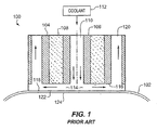
- Fig. 1 is a side midsectional view illustrating a conventional microwave applicator 100 deployed for use in microwave thermokeratoplasty operations on a cornea 102.
- An oscillator drives microwave field emissions on concentric microwave conductors, such as conductive metal tubes 104 and 106.
- a dielectric 108 fills space between the tubes 104 and 106.
- a central passageway 110 permits the flow of coolant 112 into a flow gap 114 of about 0.3 mm to 0.5 mm between a terminal antenna end 116 and a MylarTM (a trademark of E. I. du Pont de Nemours and Company Corporation, of Wilmington, Delaware) film 118.
- the flow gap 114 places the central passageway 110 influidic communication with exit annulus 120 for circulation of coolant 112.
- the MylarTM film 118 comes into direct contact with cornea 102 at interface 122, which may optionally have a concave down configuration adapted so as not to over-stress the cornea 102 by excessive flattening.
- the configuration of applicator 100 provides a microwave field that distributes itself downward through the coolant in flow gap 114 and into the cornea 102.
- the tubes 104 and 106 form an inefficient near-field applicator ideally having a penetration depth of less than about one millimeter, as opposed to a true antenna that can launch a wave.
- the small value of microwave penetration depth is an intentional design feature that is intended to protect the endothelium or back surface 124 of cornea 102 because the endothelium 124 is regarded to be incapable of regeneration after thermal damage.
- Coolant 112 flowing in the flow gap 114 cools the cornea at interface 122 by forced convection.
- the MylarTM film 118 retains the coolant 112 in flow gap 114 and also prevents the flow of electrical current from tubes 104 and 106 into the cornea 102.
- the MylarTM film 118 retains the coolant 112 in flow gap 114 and also prevents the flow of electrical current from tubes 104 and 106 into the cornea 102.
- the amount of applied energy is unpredictably related in terms of a precise biological effect, such as by administering energy to produce a predetermined amount of vision correction.
- the thermal flux at depth in the cornea can be calculated according to theory with a high degree of precision; however, the thermal flux is not calibrated to a measurable biological effect in terms of an applied treatment modality. For example, it is undetermined what level of thermal flux is required to flatten a particular cornea to a desired level of diopter adjustment. This uncertainty is exacerbated by the characteristically sudden onset of thermally-induced shrinkage in the cornea.
- the present invention overcomes the problems outlined above and advances the art by providing a microwave application device and system that is less likely to produce unintended harm, such as astigmatic effects and burning of epithelial or endothelial corneal tissues.
- the device and system is advantageously configurable for use in treatment modalities that are predictable or verifiable in their effects upon vision correction.
- the device according to the invention is an application for performing thermokeratoplasty as defined in claim 1. Preferred embodiments are defined in the dependent claims.
- thermokeratoplasty system may include an energy transmitter used for cornea-based vision correction modalities.
- an improvement to prior systems may comprise a sensor that is configured to measure a physical variable in an eye as the eye is affected by a thermokeratoplasty operation and to provide a sensor signal representative of the physical variable.
- a feedback circuit may be adapted to receive the sensor signal and analyze the sensor signal to determine when a treatment modality has achieved an intended effect.
- the senor may be configured to measure the physical variable as corneal temperature, either as a surface temperature or temperature at depth in the cornea.
- the sensor may also or alternatively be configured to measure the physical variable as heat flux in the cornea, mechanical stress of the cornea, mechanical strain of the cornea or an electrical property of the cornea, such as the phenomenon of conductivity or permittivity.
- the sensor may be configured to measure the physical variable as a mechanical property of the cornea, for example, mass density, modulus of elasticity, or a change in optical opacity associated with shrinkage of collagen in the cornea.
- the sensor signal may derive from many forms of measurement.
- the sensor signal may embody information concerning a quantity of electrical current passing through the cornea, an electrical voltage applied to the cornea, and/or electromagnetic energy applied to the cornea, such as reflected energy, transmitted energy, and energy received from tissue.
- the electromagnetic energy may be measured as an optical birefringence phenomenon and/or a microwave radiometry phenomenon.
- Ultrasonic energy may also be applied to the cornea for use in measurements, for example, as measurements of reflected energy, transmitted energy, and/or energy received from tissue.
- the sensor signal may embody information obtained from a mechanical transducer, such as a piezo-resistive or piezo-electric device that is oriented to quantify parameters including corneal elongation, corneal compression, corneal displacement, corneal velocity, corneal acceleration, local slope, local curvature, global slope, global curvature, corneal stress, and corneal pressure. These measurements may pertain to scalar, vector, or tensor variables measured at the surface of the cornea or at depth in the cornea.
- a thermal transducer may be used to determine, for example, temperature and heat flux at the surface of the cornea or at depth in the cornea.
- Useful types of thermal transducers may include, without limitation, a thermocouple, a thermistor, and a submillimeter-scale device.
- the feedback circuitry may operate by using signals and signal processing circuits, such as by processing a sensor signal according to an empirical correlation that relates the sensor signal to a predetermined vision correction effect.
- the feedback circuitry may also operate by processing the sensor signal to determine when the physical variable has been adjusted to achieve a predetermined quantity of the physical variable, such as a predetermined level of birefringence.
- At least one additional sensor may be used to provide an additional sensor signal.
- the feedback circuitry may be configured to process the sensor signals in combination to determine when the treatment modality has achieved the intended effect as a function of the respective signals.
- the microwave or radio frequency applicator is configured for direct contact with the cornea without a coolant flow gap between the microwave or radio frequency applicator and the cornea.
- the microwave applicator may include a plurality of discrete sectors that are optionally actuated by control circuitry in a selective and independent manner for the emission of microwave or radio frequency energy according to the treatment modality.
- Program instructions for the control circuitry may, for example, provide a capability to change the actuation of one or more of the plurality of discrete sectors on the basis of the sensor signal.
- the sensor may include an array of sensors each allocated to a corresponding one of the plurality of discrete sectors and linked to the feedback circuitry.
- a plurality of concentric tubes each may have a top end and a bottom surface configured to apply electrical energy for keratoplasty operations.
- a dielectric material may separate the plurality of concentric tubes from one another.
- a cooling system may be configured to cool the applicator during keratoplasty operations without flowing coolant beneath the bottom surface 116. This type of cooling system eliminates systematic errors that are introduced by virtue of having a flow gap of varying dimensions, e.g., flow gap 114 (shown in Fig. 1 ).
- the cooling system may comprise a Peltier effect or thermoelectric cooling device or a system for circulating liquid coolant in upper regions of the applicator, but not bottom regions proximate the bottom surface of the applicator.
- a vacuum positioning system may optionally be used to retain the applicator on a cornea.
- thermokeratoplasty system facilitates a thermokeratoplasty modality that employs an energy transmitter used for cornea-based vision correction modalities.
- the method of operation may, for example, include applying microwave or radio-frequency energy or other heat transmitting energy, sensing a physical variable in an eye as the eye is affected by a thermokeratoplasty operation to provide a sensor signal representative of the physical variable, receiving the sensor signal, and analyzing the sensor signal to determine when a treatment modality has achieved an intended effect.
- the present invention provides an applicator for performing thermokeratoplasty that includes a pair of microwave conducting elements that extend from a proximal end to a distal end, and that are separated from one another by a selected distance.
- a dielectric insulator is disposed between the conducting elements to provide electrical insulation therebetween.
- the application of a microwave signal across the conducting elements at the proximal end causes generation of a microwave field at the distal end.
- the conducting elements are configured to have direct contact with corneal tissue upon placement of the applicator's distal end on a subject's cornea.
- the surfaces of the conducting elements of the above applicator which are configured to have direct contact with the cornea, are at least partially coated with a thermally conductive and electrically insulating material.
- the invention provides a system for performing thermokeratoplasty that includes the above described application and applicator, a generator for applying an electrical signal to the applicator's proximal end so as to generate a radiation field at the applicator's distal end, and a controller coupled to the generator for applying control signals thereto.
- Fig. 1 shows a prior art microwave applicator
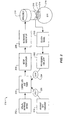
- Fig. 2 is a block schematic diagram illustrating system components of a radio-frequency or microwave thermokeratoplasty system in accordance with the principles described herein;
- Fig. 3 is a side perspective midsectional view of one microwave applicator that is improved with respect to the prior art
- Fig. 4 is a top perspective midsectional view of the microwave applicator shown in Fig. 3 ;
- Fig. 5 is a side perspective midsectional view of one microwave thermokeratoplasty applicator that may be used in place of the applicator shown in Fig. 3 ,
- Fig. 6 is a schematic diagram of an applicator according to one embodiment of the invention in which the bottom surfaces of the microwave conducting elements are coated with electrically insulating but thermally conductive layers,
- Fig. 7 is a schematic diagram of an applicator according to another embodiment of the invention in which the bottom surfaces of the microwave conducting elements, as well as at least a portion of a side surface of each conducting element, are coated with a thermally conductive and electrically insulating material, and
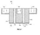
- Fig. 8 is a schematic diagram of an applicator according to yet another embodiment of the invention in which the microwave conducting elements include a rod disposed within a conducting tube.
- thermokeratoplasty system 200 that operates by sensing a physical variable in an eye and providing sensed feedback affecting a vision correction modality.
- a physician or other medical worker manually accesses an interface device 202, such as a computer keyboard, that facilitates the selection and/or initiation of a treatment modality.
- the interface device 202 may request manual input, such as a predetermined amount of diopter correction that is required for a particular patient, baseline measurements of physical variables, astigmatism measurements, wavelength of microwave radiation, intensity of microwave radiation, selection of a treatment modality by specific selection or class of modality, and/or goals for adjusted physical variables obtainable as a result of treatment.
- a programmable controller 204 accepts program instructions that optionally access user input data or program selections from the interface device 202 and causes system 200 to implement a selected vision correction modality.
- Setup verification in step 206 may be a user-interactive process that verifies the modality and assures that system 200 is correctly positioned or configured for thermokeratoplasty operations.
- a generator such as microwave or other electrical signal generator 208, produces energy that is useful for thermokeratoplasty purposes and supplies this energy, e.g., in the form of microwave or other oscillating energy, to an applicator 210.
- a near-microwave emission of 915 MHz (approved by the FCC for medical use) is preferred to reduce system cost; however, the generator 208 may be operated at other frequencies, such as 2450 MHz, that are conventionally used and understood to have therapeutic benefits according to a desired modality.
- applicator 210 produces corresponding near-field effects 212 in cornea 214 of eye 216.
- electrical energy useful in the present invention includes radiant electric energy at frequencies from about 100 kHz to 10 GigaHertz. In many applications, the preferred frequencies lie in the "microwave" region of the spectrum.
- the term "microwave" is intended to encompass radiant electrical energy oscillating at frequencies ranging from about 100MHz to about 10 GigaHz, more preferably from about 500MHz to about 3000 Mhz.
- the cornea 214 and eye 216 inherently have one or more variable physical properties (i.e., physical variables) that may be affected by the microwave or radio-frequency near-field effects 212 and the consequent temperature elevation. These physical variables may be measured by a sensor 218 to provide a sensor signal 220 that embodies a direct or indirect measurement of the physical variables. Processing circuitry 222 may receive the signal 220 and analyze the same to determine if and when the modality has achieved a desired effect that is relevant to the intended or planned outcome of the modality. Processing circuitry 222 may generate a stop signal 224 that terminates treatment when the physical variable has been modified to within a predetermined range or value.
- Sensor 218 for use with the applicator 210 may be one or more of the sensors described above, such as:
- a safety mechanism is built into program instructions for controller 204 as a clock-based maximum time override 226 that generates a stop signal 228 at the termination of a safe time interval for the selected modality. This feature may assure that operation of the microwave generator 206 does not exceed a specified amount of time at any given level of output and is intended to avoid thermal damage to the corneal epithelium, and especially the endothelium.
- Fig. 3 depicts a side elevation midsectional view of a cylindrical applicator 300 that contains several improvements over the applicator 100 of Fig. 1 .
- One such improvement is, for example, the absence of a flow gap between cornea 302 and a bottom surface 304 of applicator 300, such that no coolant circulates below applicator 300 or in the lower region 305, e.g., the bottom ten percent or so of applicator 300 proximate to cornea 302.
- an outer insulated microwave-conductive tube 306 circumscribes an inner insulated tube 308 that is also microwave conductive. Tubes 306 and 308 are concentric. A dielectric material 310 may separate tube 306 from tube 308. It should be appreciated that the term "tube” as used herein encompasses both cylindrical elements and metallic coatings that function like a freestanding conductive cylinder.
- a microwave conductive tube can be a metallic coating on a nonmetallic, tubular-shaped, material.
- the spacing between tubes 306 and 308 controls penetration depth of microwave energy according to established microwave field theory.
- chambers 312, 314, and 316 are configured for bidirectional coolant flow providing a predetermined amount of cooling from coolant (e.g., coolant 112, Fig. 1 ). Such flow is optionally regulated by controller 204 (see Fig. 2 ) to achieve a maximum temperature at mid-depth in cornea 302, for example, according to established thermal flux theory.
- the outer diameter of the inner conductive tube 308 is preferably larger than the pupil of the patient's eye.
- the outer diameter of the inner conductor also may be selected so as to have a greater or lesser effect on the change in keratometry induced by the microwave keratoplasty treatment.
- the inner diameter of the outer conductive tube 306 is selected so as to generate a desired gap between the two conductive tubes. In some embodiments, this gap is sufficiently small, e.g., in a range of about 0.1 mm to about 2.0 mm, so as to spare the endothelial layer of the cornea (posterior surface) from exposure to elevated temperatures during corneal treatment by the applicator.
- the outer diameter of the inner conductor 308 ranges from about 2 to about 10 mm while the inner diameter of the outer conductor 306 ranges from about 2.1 to about 12 mm.
- the inner and the outer conductive tubes 306 and 308 can be formed, for example, of aluminum, stainless steel, brass, copper, other metals, metal-coated plastic, or any other suitable material. At least a portion of each of the conductive tubes 306 and 308 is covered with an electrical insulator to prevent, for example, concentration of electrical current in the area of contact between the corneal tissue and the conductors.
- the conductive tubes, or at least a portion thereof are coated with a non-metallic material that can function both as an electrical insulator as well as a thermal conductor. The coating can be accomplished by employing, for example, a vapor deposition or a spray process.
- a nonmetallic electrically insulating layer can be bonded to the metallic conductive tubes by employing, e.g., a hot isostatic press method, powder metallurgy with differential layers, or frictional welding.
- metallic conductive tubes 306 and 308, or a portion thereof can be covered with plastic deposited thereon by employing, for example, a dipping process, a spinning process, or any other suitable process known in the art.
- a coating disposed on the conductive tubes 306 and 308 can exhibit a graded thermal conductivity.
- a metal matrix composite material such as alumina having a differential concentration of aluminum oxide particles in an aluminum matrix
- the coating material closest to the cornea and the outside surface of the applicator has the highest thermal conductivity, e.g., the highest concentration of aluminum oxide particles when the coating material is alumina, while the other portions of the coating, e.g., the portions that coat central section of the applicator, contain a lower thermal conductivity, e. g., a lower concentration of aluminum oxide particles.
- a bottom dielectric layer 318 may protect cornea 302 from deleterious temperature effects of electrical conduction current that, otherwise, would flow into cornea 302 from the tubes 306 and 308.
- the bottom dielectric layer 318 may separate bottom surface 304 from cornea 302.
- the dielectric layer 318 may be thin enough to minimize interference with microwave emissions and thick enough to prevent superficial deposition of electrical energy by flow of conduction current; superficial flow of a conduction current could interfere with the goal of achieving a mid-depth maximum temperature in cornea 302.
- the dielectric layer 318 may be a biocompatible material, such as Teflon, deposited to a thickness of about 0.05 mm (0.002 inches).
- the dielectric layer 318 may be a thermal conductor, such as hard-coat anodizing.
- the microwave conducting tubes 306 and 308 Upon positioning of the applicator on a patient's cornea, the microwave conducting tubes 306 and 308 have "direct contact" with the corneal tissue.
- the phrase "direct contact”, as used herein, indicates that no fluid, such as, a coolant fluid, flows between the bottom surfaces of the microwave conductive tubes 306 and 308 and the corneal tissue.
- the conducting tubes can have a direct contact with the corneal tissue even if a thin layer of a material, such as, the dielectric layer 318, separates the bottom surfaces of the conducting tubes from the corneal tissue so long as the interposing layer does not substantially interfere with the strength of the microwave field established between the conducting tubes, and hence its penetration into the corneal tissue.
- the interposing layer can be employed while maintaining direct contact between the conducting tubes and the corneal tissue so long as the interposing layer does not prevent generation of a desired heating pattern in the corneal tissue by exposure of the tissue to a microwave radiation field generated between the conducting tubes at the applicator's distal end.
- the pattern of microwave heating in tissue has substantially the same shape and dimension as the gap between the two microwave conductors.
- the pattern of microwave heating in tissue may be, for example, a circle with a diameter less than that of the inner conducting tube or rod, rather than being an annulus with dimensions equal to that of the gap between the conductors.
- An annulus is a preferred heating pattern because the inner diameter of the heated annulus can be selected to be sufficiently large so as to avoid heating the central cornea overlying the pupil. Central heating of the corneal can be deleterious due to a temporary opacity that can be associated with such heating.
- a layer of fluid coolant can have a thickness that varies by about 0.13 mm (0.005 inches) across the distal end of the application as a result of typical machining errors.
- Such a variation may comprise a significant fraction of a nominal thickness of the coolant layer because the nominal thickness may be selected to be sufficiently small so as to render the heating pattern geometrically similar to the gap between the conductors.
- the nominal thickness of the layer of fluid coolant may be selected to be about 0.51 mm (0.020) inches.
- the actual thickness can vary between 0.38 mm (0.015 inches) to 0.51 mm (0.02 inches) (i. e., by about 33 percent) due to typical machining errors, thus causing the microwave heating to vary significantly across the applicator's distal end.
- an applicator configuration providing direct contact eliminates such variations of microwave heating across the applicator's distal end, which is otherwise a sensitive function of the thickness of the coolant layer.
- the layer 318 is formed of a thermally conductive but electrically insulating material.
- the thermal conductivity of the layer 318 can be in a range of about 0.1W/ (m oC) to about 500W/ (m oC), and more preferably, in a range of about 2W/ (m oC) to about 200W/ (m oC).
- the layer 318 can be formed of anodized aluminum, having a thickness in a range of about 0.025 mm (0.001 inches) to about 0.05 mm (0.002 inches), that not only provides electrical insulation between the electrodes and the corneal tissue but also provides good thermal contact with the corneal tissue for extracting heat therefrom.
- the sensor 218 may be a type of sensor described above, and may, for example, comprise embedded microelectronic devices 320, 322 and/or 324 in the tubes 306 and 308, devices such as sensors 326 and/or 328 embedded in the dielectric material 310, or optional separate sensors such as sensor 330 deployed outside of applicator 300.
- the dielectric layer 318 is, for example, a grid of thin film transducers each operating as a wheatstone bridge.
- a transparent window 334 may be used to quantify the refractive effect of treatment with optical instrumentation, such as a videokeratoscope.
- vacuum passages 336 and 338 pass through the dielectric material 310, and connect to a vacuum source 340 for purposes of enhancing retention of applicator 300 in a fixed position relative to cornea 302 during treatment.
- the vacuum source 340 can apply a controlled amount of suction to the cornea to ensure firm and even contact of the applicator's bottom surface with the cornea.
- Chambers 312, 314, and 316 may be filled with a heat sink in thermal communication with an optional thermoelectric cooler device 342 that operates, for example, using a Peltier effect under the control of controller 204.
- Fig. 4 is a top midsectional view of applicator 300.
- Each of the tubes 306 and 308 may be divided into a plurality of discrete sectors or sections, which in Fig. 4 are quartile sections of coaxial extension, such as quartile sections 400, 402, 404, and 406 in the case of tube 306.
- Each of these sections 400-406 may be separately coupled with controller 204 (shown in Fig. 2 ) for individual operation where, for example, microwave radiation of different intensity, duty cycle, waveform, frequency, or duration may be applied to any one section, or the sections 400-406 may be driven wholly or partially in unison.
- controller 204 shown in Fig. 2
- the capability to drive discrete sections facilitates treatment of native astigmatism in the patient, and it offers further capacity not heretofore found, which is to provide modalites that are custom tailored to address a variety of diopter adjustments in optimized fashion by selectively providing more or less treatment energy to sections in a radially outboard pattern.
- Fig. 5 is a side elevation midsectional view of a cylindrical microwave or radio-frequency thermokeratoplasty applicator 500 that may be used in place of applicator 300.
- An outer insulated electrically-conductive tube 502 may circumscribe an inner telescoping insulated tube 504 that is also electrically- conductive.
- Inner tube 504 may be formed in at least two telescoping sections 506 and 508 that are in electrical contact with one another.
- the tubes 502 and 504 may be concentric.
- a dielectric material 510 may separate tube 502 from section 508. The spacing between tubes 502 and 504 controls penetration depth of microwave or radio- frequency energy according to established microwave and radio-frequency field theory.
- Chambers 512, 514, and 516 are configured for bidirectional coolant flow (e. g., as flow 518) generally as described with respect to applicator 300.
- An annular air gap 520 may surround the telescoping tube 504.
- Bottom surfaces 522 and 524 may be contoured to conform with an eye, e. g., generally to conform with a spherical shape established by ball-milling processes. Alternatively, such contoured surfaces can be curved, beveled or chamfered.
- bottom surfaces 522 and 524 are coated with a material 526 that is both dielectric and heat conductive, such as Teflon powder coating material, or anodizing material.
- the tubes 502 and 504 are formed of aluminum and the anodizing material coating the bottom surfaces 522 and 524 includes a layer of aluminum oxide having a thickness, e. g., in a range of about 0.13 mm (0.0005) inches to about 0.25 mm (0.010 inches), and more preferably in a range of about 0.025 mm (0.001 inches) to about 0.05 mm (0.002 inches).
- the material 526 may protect cornea 528 from deleterious temperature effects of electrical conduction current that, otherwise, would flow into cornea 528 from the tubes 502 and 504, according to principles described generally above with respect to applicator 300.
- Section 504 may telescope axially over section 506, as shown by a double-headed arrow 530, to assure that material 526 is positioned in full contact with cornea 528. This sliding action may be facilitated by gravity or positive pressure exerted by coolant flowing in chamber 516. A vacuum pump 532 may also be used to exert a mild vacuum within chamber 516 to force this contact. Alternatively, a screw mechanism (not shown) may be positioned in air gap 520 to provide fixed and repeatable adjustments to the height of section 504.
- Applicator 500 can include a sensor, e.g., sensor 218, which can, for example, include outside sensors 534 deployed outside of applicator 500 and/or embedded sensor devices not shown in Fig. 5 .
- a second sensing device 536 may be used to sense whether full contact exists between the tubes 502, 504, and the cornea 528. Corneal tissue contains relatively high amounts of water and is conductive. Thus, a voltage V applied to outer tube 502 may be sensed by the second sensing device 536 as a resistance or capacitance. The magnitude of resistance or capacitance may be correlated to the amount of contact between applicator 500 and cornea 528.
- a signal from the second sensor 536 may be used as part of the feedback system through processor circuitry 222 ( Fig. 2 ) or may be operated independently of the feedback system and used solely as a means to assure contact between applicator 500 and cornea 528.
- Fig. 6 schematically illustrates an applicator 600 according to another embodiment of the invention that includes two elongated microwave conducting elements 610 and 612, having generally tubular structures, that are coaxially positioned at a selected distance relative to one another.
- An electrically insulating element 614 separates the two conducting elements 610 and 612, and provides electrical insulation therebetween.
- the applicator 600 further includes chambers 606, 618, and 620 that allow bi-directional flow of a coolant fluid employed for cooling the electrodes 610 and 612, and consequently, corneal tissue treated with microwave radiation.
- the conducting element 610 and 612 include bottom surfaces 610a and 612a, respectively, that are coated with layers 622 and 624, which are electrically insulating and thermally conductive.
- the coating layers 622 and 624 can be, for example, hard-coat anodized aluminum layers that electrically insulate the corneal tissue from the conducting elements 610 and 612 while allowing heat generated in the corneal tissue, e.g., in response to absorption of microwave energy applied by the applicator thereto, to be dissipated, e.g., by transfer to the coolant fluid flowing in the reservoirs 606, 618 and 620 via conducting elements 610 and 612.
- each of the coating layers 622 and 624 can be deposited as a separate layer on the respective surface of the conducting elements on which it is disposed. Alternatively, each of the coating layers 622 and 624 can form a unitary structure with the surface on which it is disposed.
- the conducting elements 610 and 612 can be formed of aluminum, and each of the coating layers 622 and 624 can be aluminum oxide layers formed, example, by oxidizing a portion of each conducting element.
- the elemental composition of the coating layer changes continuously across its boundary with the underlying surface of the conducting element from the composition in the bulk of the coating layer to that in the bulk of the conducting element on which the coating layer is disposed.
- the coating layers 622 and 624 are plastic layers having a thickness in a range of about 0.025 mm (0.001 inches) to about 0.1 mm (0.004 inches), and more preferably, in a range of about 0.025 mm (0.001 inches) to about 0.05 mm (0.002 inches).
- Fig. 7 schematically depicts another embodiment of a microwave applicator 700 according to the teachings of the invention in which coating layers 710 and 712 not only cover bottom surfaces of microwave conducting elements 714 and 716, respectively, but they also extend along at least a portion of a tubular wall of each of these conductive elements.
- the coating layers 710 and 712 are preferably formed of an electrically insulating but thermally conductive material, e. g., hard-coat anodized aluminum.
- Such composition of the coating material allows the coating layers to insulate electrically corneal tissue from the conductive elements while facilitating transfer of heat from the corneal tissue to a coolant fluid circulating through chambers 718, 720, and 722.
- the device can be secure to the cornea via vacuum passage 724 and can include a contoured bottom to better conform to the corneal topography, if desired.
- the thermal conductivity of the coating layers 710 and 712 are substantially spatially uniform, in other embodiments, the coating layers exhibit a graded thermal conductivity.
- the thermal conductivity of the coating layer 710 can increase in direction A such that the portions of the coating layer that are closer to the corneal tissue have a higher thermal conductivity relative to those portions that are farther away.
- the concentration of the aluminum oxide particles can vary in the coating, for example, it can be higher in portions closer to the applicator's distal end, so as to provide a desired gradation of thermal conductivity.
- an applicator 800 employs a microwave conducting rod 810, rather than a tube, as its inner microwave conducting element.
- the rod is disposed within an outer conducting tube 812 that forms the applicator's outer microwave conducting element.
- an electrical insulator 814 separates the outer conducting tube 812 from the inner conducting rod 810.
- Each of two chambers 816 and 820, thermally coupled to the outer conductive tube 812, allows bi-directional flow of a coolant fluid for extracting heat from the outer conducting tube 812.
- a chamber 818 which also allows a bi-directional flow of a coolant fluid, is thermally coupled to the inner rod for extracting heat therefrom.
- the rod 810 can have a diameter in a range of about 2 mm to about 10 mm, and more preferably, in a range of about 6 mm to about 8 mm while the outer conducting tube 812 can have an inner diameter in a range of about 2.5 mm to about 12 mm, and an outer diameter in a range of about 3mm to about 15 mm.
- the rod's diameter is preferably selected to be larger than the pupil of the subject's eye.
- the tubular insulating element 814 can have a thickness in a range of about 0.1 mm to about 2 mm, and more preferably in a range of about 0.5 mm to about 1 mm. This thickness defines the size of a gap between the rod 810 and the outer conducting tube 812.
- a portion of the microwave conducting elements 810 and 812 is coated with an electrically insulating material, which is thermally conductive, to electrically insulate these elements from the corneal tissue upon positioning of the applicator on a subject's cornea.
- an electrically insulating material which is thermally conductive
- layers 822 and 824 formed of an electrically insulating and thermally conducting material, e.g., alumina, are disposed on bottom surfaces of the inner rod 810 and the outer tube 812, respectively, for providing electrical insulation.
Claims (33)
- Applicateur (210, 300, 500, 600, 700, 800) destiné à effectuer une thermokératoplastie, comportant :une paire d'éléments conducteurs électriques (306, 308, 502, 504, 610, 612, 714, 716, 810, 812) séparés par une distance sélectionnée et s'étendant d'une extrémité proximale à une extrémité distale, chacun desdits éléments conducteurs (306, 308, 502, 504, 610, 612, 714, 716, 810, 812) comportant une surface inférieure (304, 522, 524, 610a, 612a) à ladite extrémité distale, lesdites surfaces inférieures (304, 522, 524, 610a, 612a) étant au moins partiellement revêtues d'un matériau thermiquement conducteur et électriquement isolant (318, 526, 622, 624, 710, 712, 822, 824) et configurées pour un positionnement au-dessus de la cornée d'un patient (214, 302, 528), etun isolant diélectrique (310, 510, 614, 724, 814) disposé entre lesdits éléments conducteurs (306, 308, 502, 504, 610, 612, 714, 716, 810, 812) pour assurer une isolation électrique entre ceux-ci,dans lequel l'application d'un signal électrique à travers lesdits éléments conducteurs (306, 308, 502, 504, 610, 612, 714, 716, 810, 812) à ladite extrémité proximale entraîne la génération d'un champ électrique à ladite extrémité distale.
- Applicateur (210, 300, 500, 600, 700, 800) selon la revendication 1, dans lequel ledit matériau thermiquement conducteur et électriquement isolant (318, 526, 622, 624, 710, 712, 822, 824) comporte de l'aluminium anodisé, de l'alumine ou une matière plastique.
- Applicateur (210, 300, 500, 600, 700, 800) selon la revendication 1 ou la revendication 2, dans lequel les éléments conducteurs (306, 308, 502, 504, 610, 612, 714, 716, 810, 812) sont agencés sous la forme d'une paire de conducteurs allongés, et comportant une source de vide (340, 532) ayant au moins un passage sous vide (336, 338, 724) s'étendant jusqu'à ladite extrémité distale et configurée pour appliquer une aspiration à au moins une partie de tissu cornéen lors d'un positionnement dudit applicateur (210, 300, 500, 600, 700, 800) sur la cornée (214, 302, 528).
- Applicateur (300, 700) selon la revendication 3, dans lequel ledit passage sous vide (336, 338, 724) passe au moins partiellement à travers ledit isolant (310, 724).
- Applicateur (210, 300, 500, 600, 700, 800) selon la revendication 3 ou la revendication 4, comportant en outre au moins un élément de transfert thermique (312, 314, 316, 512, 514, 516, 606, 618, 620, 718, 720, 722, 816, 818, 820) thermiquement couplé à au moins un desdits conducteurs allongés (306, 308, 502, 504, 610, 612, 714, 716, 810, 812) afin de réguler la température de celui-ci, dans lequel ledit élément de transfert thermique (312, 314, 316, 512, 514, 516, 606, 618, 620, 718, 720, 722, 816, 818, 820) comporte en particulier une chambre (512, 514, 516, 606, 618, 620, 718, 720, 722, 816, 818, 820) à travers laquelle un fluide peut s'écouler.
- Applicateur (210, 300, 500, 600, 700, 800) selon l'une quelconque des revendications 1 à 5, comportant
un dispositif de refroidissement (312, 314, 316, 512, 514, 516, 606, 618, 620, 718, 720, 722, 816, 818, 820) thermiquement couplé au matériau thermiquement conducteur et électriquement isolant (318, 526, 622, 624, 710, 712, 822, 824) pour un refroidissement de celui-ci. - Applicateur (210, 300, 500, 600, 700, 800) selon l'une quelconque des revendications 2 à 6, dans lequel ledit matériau thermiquement conducteur et électriquement isolant (318, 526, 622, 624, 710, 712, 822, 824) fournit une couche électriquement isolante entre ladite extrémité distale dudit élément conducteur électrique (306, 308, 502, 504, 610, 612, 714, 716, 810, 812) et la partie du tissu cornéen à laquelle de l'énergie électrique est couplée, et/ou a une conductivité thermique dans une plage d'environ 0,1 W/(m° C) à environ 200 W/(m° C).
- Applicateur (210, 300, 500, 600, 700, 800) selon l'une quelconque des revendications 1 à 7, dans lequel ladite paire d'éléments conducteurs électriques (306, 308, 502, 504, 610, 612, 714, 716, 810, 812) comporte un tube conducteur intérieur (308, 504, 612, 716, 810) disposé à l'intérieur d'un tube conducteur extérieur (306, 502, 610, 714, 812), dans lequel lesdits tubes conducteurs (306, 308, 502, 504, 610, 612, 714, 716, 810, 812) sont en particulier disposés de manière sensiblement coaxiale les uns par rapport aux autres, et/ou ledit tube conducteur intérieur (308, 504, 612, 716, 810) a un diamètre extérieur dans une plage d'environ 2 à environ 10 mm, et/ou ledit tube conducteur extérieur (306, 502, 610, 714, 812) a un diamètre intérieur dans une plage d'environ 2,5 à environ 12 mm.
- Applicateur (210, 300, 500, 600, 700, 800) selon l'une quelconque des revendications 1 à 7, dans lequel ladite paire d'éléments conducteurs électriques comporte une tige conductrice intérieure (810) disposée à l'intérieur d'un tube conducteur (812) dans lequel ledit élément conducteur électrique (810, 812) est en particulier formé d'un métal ayant un revêtement électriquement isolant et thermiquement conducteur (318, 526, 622, 624, 710, 712, 822, 824), le métal formant l'élément conducteur électrique (810, 812) étant de préférence un métal quelconque parmi l'acier inoxydable, l'acier, l'aluminium, le laiton ou le cuivre, et/ou ledit revêtement (318, 526, 622, 624, 710, 712, 822, 824) comporte de l'alumine et/ou une matière plastique.
- Applicateur (210, 300, 500, 600, 700, 800) selon la revendication 9, dans lequel ledit revêtement d'alumine (318, 526, 622, 624, 710, 712, 822, 824) comporte des particules d'oxyde d'aluminium dans une matrice d'aluminium de telle sorte qu'une concentration desdites particules d'oxyde d'aluminium varie de ladite extrémité proximale à ladite extrémité distale dudit élément conducteur électrique (810, 812), dans lequel la concentration desdites particules d'oxyde d'aluminium atteint en particulier une valeur maximale à proximité de ladite extrémité distale.
- Applicateur (210, 300, 500, 600, 700, 800) selon l'une quelconque des revendications 1 à 10, dans lequel l'extrémité distale d'au moins un desdits conducteurs (306, 308, 502, 504, 610, 612, 714, 716, 810, 812) comporte un embout ayant une surface galbée, ladite surface galbée étant en particulier configurée pour s'adapter sensiblement à ladite partie de la cornée du patient (214, 302, 528).
- Applicateur (800) selon l'une quelconque des revendications précédentes, comportant le premier de la paire d'éléments conducteurs électriques (810, 812) agencé sous la forme d'un tube électriquement conducteur (812) s'étendant d'une extrémité proximale à une extrémité distale, et le second de la paire d'éléments conducteurs électriques (810, 812) agencé sous la forme d'une tige conductrice (810) disposée à l'intérieur dudit tube (812) et séparée de celui-ci par une distance sélectionnée.
- Applicateur (210, 300, 500, 600, 700, 800) selon l'une quelconque des revendications précédentes, comportant une pluralité de tubes concentriques (306, 308, 502, 504, 610, 612, 714, 716, 810, 812) ayant chacun une extrémité supérieure et une surface inférieure (304, 522, 524, 610a, 612a) configurées pour appliquer un rayonnement à ladite cornée (214, 302, 528) pour des opérations de kératoplastie ; ledit isolant diélectrique (310, 510, 614, 724, 814) séparant la pluralité de tubes concentriques (306, 308, 502, 504, 610, 612, 714, 716, 810, 812) les uns des autres ; et un système de refroidissement configuré pour refroidir l'applicateur (210, 300, 500, 600, 700, 800) pendant des opérations de kératoplastie sans écoulement de fluide de refroidissement adjacent à la surface inférieure (304, 522, 524, 610a, 612a).
- Applicateur (210, 300, 500, 600, 700, 800) selon la revendication 13, dans lequel le système de refroidissement comporte un dispositif à effet Peltier.
- Applicateur (210, 300, 500, 600, 700, 800) selon la revendication 13 ou 14, comportant en outre un système de positionnement sous vide, et/ou comportant également des capteurs intégrés (218) positionnés pour mesurer une ou plusieurs variables physiques et capables de délivrer des signaux de rétroaction des variables physiques concernant des opérations de thermokératoplastie et/ou des moyens pour commander la pluralité de tubes (306, 308, 502, 504, 610, 612, 714, 716, 810, 812) par l'utilisation d'un signal de rétroaction pendant des opérations de thermokératoplastie.
- Applicateur (300) selon l'une quelconque des revendications 13 à 15, dans lequel au moins un parmi la pluralité de tubes (306, 308) est divisé en secteurs séparés (400, 402, 404, 406), dans lequel les secteurs séparés (400, 402, 404, 406) comportent en particulier des éléments de tube télescopiques, ou les secteurs séparés (400, 402, 404, 406) comportent des éléments s'étendant conjointement longitudinalement, séparés d'un contact électrique les uns avec les autres.
- Système (200) pour effectuer une thermokératoplastie, comportant un applicateur (210, 300, 500, 600, 700, 800) selon l'une quelconque des revendications précédentes et comportant en outre un générateur (208) pour appliquer un signal électrique ayant une fréquence sélectionnée à travers lesdits éléments conducteurs (306, 308, 502, 504, 610, 612, 714, 716, 810, 812) à ladite extrémité proximale de manière entraîner la génération d'un champ de rayonnement à ladite extrémité distale, et
une commande (204) couplée audit générateur (208) pour appliquer des signaux de commande à celui-ci. - Système (200) selon la revendication 17, dans lequel lesdits signaux de commande entraînent un événement quelconque parmi le déclenchement d'un protocole de traitement ou la fin d'un protocole de traitement, et/ou ladite commande (204) applique un signal d'arrêt (228) audit générateur (208) lorsqu'un temps de traitement associé à un protocole de traitement dépasse un seuil défini pour ladite modalité de traitement.
- Système (200) selon l'une quelconque des revendications 17 à 18 incluant un applicateur (210, 300, 500, 600, 700, 800) utilisé pour des modalités de correction de vision basées sur la cornée, et comportant
un capteur (218) configuré pour mesurer une variable physique dans un oeil (216) lorsque l'oeil (216) est affecté par une opération de thermokératoplastie et pour délivrer un signal de capteur (220) représentatif de la variable physique ; et un système de rétroaction adapté pour recevoir le signal de capteur (220) et analyser le signal de capteur (220) afin de déterminer lorsqu'une modalité de traitement a atteint un effet voulu. - Système (200) selon la revendication 19, dans lequel le capteur (218) est configuré pour mesurer la variable physique sous forme de température cornéenne.
- Système (200) selon la revendication 20, dans lequel le capteur (218) est configuré pour mesurer la température cornéenne sous forme de température de surface de cornée, ou dans lequel le capteur (218) est configuré pour mesurer la température de cornée en profondeur.
- Système (200) selon la revendication 19, dans lequel le capteur (218) est configuré pour mesurer la variable physique sous forme de flux de chaleur cornéen.
- Système (200) selon la revendication 19, dans lequel le capteur (218) est configuré pour mesurer la variable physique sous forme de contrainte mécanique cornéenne ou de déformation mécanique cornéenne, ou une propriété électrique cornéenne, en particulier sous forme de phénomène de conductivité ou de permittivité.
- Système (200) selon la revendication 19, dans lequel le capteur (218) est configuré pour mesurer la variable physique sous la forme d'une propriété mécanique cornéenne, en particulier la propriété mécanique cornéenne choisie parmi le groupe constitué de la densité massique et du module d'élasticité, et/ou dans lequel le capteur (218) est configuré pour mesurer la propriété mécanique sous la forme d'un changement d'opacité optique associé à une rétraction on réduction du collagène cornéen, et/ou dans lequel le signal de capteur (220) contient des informations concernant une quantité de courant électrique passant à travers une cornée (214, 302, 528), et/ou dans lequel le signal de capteur (220) contient des informations concernant une tension électrique appliquée à une cornée (214), et/ou dans lequel le signal de capteur (220) contient des informations concernant de l'énergie électromagnétique appliquée à une cornée (214), en particulier choisie parmi le groupe constitué d'énergie réfléchie, d'énergie transmise et d'énergie reçue d'un tissu, ou des informations concernant de l'énergie électromagnétique mesurée sous la forme d'un phénomène de biréfringence optique.
- Système (200) selon la revendication 24, dans lequel le signal de capteur (220) contient des informations concernant l'énergie électromagnétique mesurée sous la forme d'un phénomène de radiométrie hyperfréquence ou micro-onde.
- Système (200) selon la revendication 19, dans lequel le signal de capteur (220) contient des informations concernant de l'énergie ultrasonore appliquée à une cornée (214, 302, 528), en particulier choisie parmi le groupe constitué d'énergie réfléchie, d'énergie transmise et d'énergie reçue d'un tissu.
- Système (200) selon la revendication 19, dans lequel le signal de capteur (220) contient des informations obtenues à partir d'un transducteur mécanique, dans lequel le transducteur mécanique fonctionne en particulier selon un principe choisi parmi le groupe constitué d'effets piézorésistifs et piézoélectriques, et/ou dans lequel le signal de capteur (220) contient en particulier des informations choisies parmi le groupe constitué d'un allongement cornéen, d'une compression cornéenne, d'un déplacement cornéen, d'une vitesse cornéenne, d'une accélération cornéenne, d'une pente locale, d'une courbure locale, d'une pente globale, d'une courbure globale, d'une contrainte cornéenne et d'une pression cornéenne, et/ou dans lequel le signal de capteur (220) contient en particulier des informations choisies parmi le groupe constitué de variables scalaires, vectorielles et tensorielles mesurés à la surface d'une cornée (214, 302, 528), et/ou dans lequel le signal de capteur (220) contient en particulier des informations choisies parmi le groupe constitué de variables scalaires, vectorielles et tensorielles mesurés en profondeur dans une cornée (214, 302, 528).
- Système (200) selon la revendication 19, dans lequel le signal de capteur (220) contient des informations obtenues à partir d'un transducteur thermique, dans lequel en particulier le signal de capteur (220) contient des informations choisies parmi le groupe constitué d'une température et d'un flux thermique à la surface d'une cornée (214, 302, 528), et/ou dans lequel le signal de capteur (220) contient des informations choisies parmi le groupe constitué d'une température et d'un flux thermique en profondeur dans une cornée (214, 302, 528), et/ou dans lequel le transducteur thermique est un type choisi parmi le groupe constitué d'un thermocouple, d'une thermistance et d'un dispositif à échelle submillimétrique.
- Système (200) selon la revendication 19, dans lequel le système de rétroaction fonctionne en traitant le signal de capteur (220) en fonction d'une corrélation empirique qui associe le signal de capteur (220) à un effet de correction de vision prédéterminé, ou dans lequel le système de rétroaction fonctionne en traitant le signal de capteur (220) pour déterminer lorsque la variable physique a été ajustée afin d'obtenir une quantité prédéterminée de la variable physique.
- Système (200) selon l'une quelconque des revendications 19 à 29, comportant en outre au moins un capteur supplémentaire (218) qui délivre un signal de capteur supplémentaire (220), l'ensemble de circuits de rétroaction étant configuré pour traiter le signal de capteur (220) et le signal de capteur supplémentaire (220), de manière combinée, afin de déterminer lorsque la modalité de traitement a atteint l'effet voulu, et/ou comportant également un applicateur hyperfréquence ou radiofréquence (210, 300, 500, 600, 700, 800), et/ou comportant également l'applicateur hyperfréquence ou radiofréquence (210, 300, 500, 600, 700, 800) incluant une pluralité de secteurs séparés (400, 402, 404, 406), dans lequel la pluralité de secteurs séparés (400, 402, 404, 406) sont des parties segmentées d'un tube (306, 308, 502, 504, 610, 612, 714, 716, 810, 812) qui peuvent être actionnées de manière sélective pour l'émission d'énergie électrique en fonction de la modalité de traitement.
- Système (200) selon la revendication 30, comportant en outre un ensemble de circuits de commande (222) pour actionner la pluralité de secteurs séparés (400, 402, 404, 406) pour émettre de l'énergie électrique en fonction de la modalité de traitement, comportant également en particulier des instructions de programme pour l'ensemble de circuits de commande (222) donnant une capacité à changer l'actionnement d'un ou plusieurs secteurs parmi la pluralité de secteurs séparés (400, 402, 404, 406) sur la base du signal de capteur (220).
- Système (200) selon la revendication 31, le capteur (218) comportant un groupe de capteurs (218), chacun étant affecté à un secteur correspondant parmi la pluralité de secteurs séparés (400, 402, 404, 406) et relié au système de rétroaction.
- Système (200) selon la revendication 19, dans lequel l'applicateur (210, 300, 500, 600, 700, 800) inclut au moins un élément tubulaire télescopique (504) configuré pour un ajustement de position de l'élément tubulaire télescopique (504) par rapport à une cornée (214, 302, 528) lorsque l'applicateur (210, 300, 500, 600, 700, 800) est déployé pour une utilisation lors d'opérations de thermokératoplastie, et/ou comportant en outre des moyens pour détecter si l'applicateur (210, 300, 500, 600, 700, 800) est en contact avec la cornée (214, 302, 528) lorsque l'applicateur (210, 300, 500, 600, 700, 800) est déployé pour une utilisation dans des opérations de thermokératoplastie.
Priority Applications (3)
| Application Number | Priority Date | Filing Date | Title |
|---|---|---|---|
| EP10183764.9A EP2269531B1 (fr) | 2002-12-09 | 2003-12-09 | Système de thermokératoplastie |
| EP20100183746 EP2269530A3 (fr) | 2002-12-09 | 2003-12-09 | Systèmes de thermokératosplastie |
| EP09180340A EP2186488A1 (fr) | 2002-12-09 | 2003-12-09 | Système de thermokératoplastie à électro-induction |
Applications Claiming Priority (5)
| Application Number | Priority Date | Filing Date | Title |
|---|---|---|---|
| US314670 | 2002-12-09 | ||
| US10/314,670 US7377917B2 (en) | 2002-12-09 | 2002-12-09 | Feedback control of thermokeratoplasty treatments |
| US730327 | 2003-12-08 | ||
| US10/730,327 US7192429B2 (en) | 2002-12-09 | 2003-12-08 | Thermokeratoplasty systems |
| PCT/US2003/038978 WO2004052223A2 (fr) | 2002-12-09 | 2003-12-09 | Systemes de thermokeratoplastie |
Related Child Applications (1)
| Application Number | Title | Priority Date | Filing Date |
|---|---|---|---|
| EP09180340.3 Division-Into | 2009-12-22 |
Publications (2)
| Publication Number | Publication Date |
|---|---|
| EP1575435A2 EP1575435A2 (fr) | 2005-09-21 |
| EP1575435B1 true EP1575435B1 (fr) | 2010-03-10 |
Family
ID=33554842
Family Applications (1)
| Application Number | Title | Priority Date | Filing Date |
|---|---|---|---|
| EP20030796799 Expired - Lifetime EP1575435B1 (fr) | 2002-12-09 | 2003-12-09 | Systeme de thermokeratoplastie a electro-induction |
Country Status (5)
| Country | Link |
|---|---|
| US (2) | US7713268B2 (fr) |
| EP (1) | EP1575435B1 (fr) |
| AU (1) | AU2003297734A1 (fr) |
| CA (1) | CA2511767A1 (fr) |
| WO (1) | WO2004052223A2 (fr) |
Families Citing this family (32)
| Publication number | Priority date | Publication date | Assignee | Title |
|---|---|---|---|---|
| US7377917B2 (en) * | 2002-12-09 | 2008-05-27 | The Trustees Of Dartmouth College | Feedback control of thermokeratoplasty treatments |
| WO2004052223A2 (fr) * | 2002-12-09 | 2004-06-24 | The Trustees Of Dartmouth College | Systemes de thermokeratoplastie |
| US8348936B2 (en) | 2002-12-09 | 2013-01-08 | The Trustees Of Dartmouth College | Thermal treatment systems with acoustic monitoring, and associated methods |
| US8202272B2 (en) | 2007-07-19 | 2012-06-19 | Avedro, Inc. | Eye therapy system |
| US8992516B2 (en) * | 2007-07-19 | 2015-03-31 | Avedro, Inc. | Eye therapy system |
| EP2227197A4 (fr) | 2007-12-05 | 2011-06-22 | Avedro Inc | Système de thérapie oculaire |
| US8469952B2 (en) * | 2008-01-23 | 2013-06-25 | Avedro, Inc. | System and method for positioning an eye therapy device |
| US8348935B2 (en) | 2008-01-23 | 2013-01-08 | Avedro, Inc. | System and method for reshaping an eye feature |
| US20090187173A1 (en) * | 2008-01-23 | 2009-07-23 | David Muller | System and method for reshaping an eye feature |
| US8409189B2 (en) * | 2008-01-23 | 2013-04-02 | Avedro, Inc. | System and method for reshaping an eye feature |
| US20090275936A1 (en) * | 2008-05-01 | 2009-11-05 | David Muller | System and method for applying therapy to an eye using energy conduction |
| JP2012501788A (ja) * | 2008-09-11 | 2012-01-26 | アヴェドロ・インコーポレーテッド | 眼治療システム |
| US8398628B2 (en) * | 2008-09-19 | 2013-03-19 | Avedro, Inc. | Eye therapy system |
| US8366689B2 (en) | 2008-09-30 | 2013-02-05 | Avedro, Inc. | Method for making structural changes in corneal fibrils |
| US8460278B2 (en) * | 2008-10-01 | 2013-06-11 | Avedro, Inc. | Eye therapy system |
| WO2010056848A1 (fr) * | 2008-11-11 | 2010-05-20 | Avedro, Inc. | Système de thérapie oculaire |
| WO2010115109A1 (fr) * | 2009-04-02 | 2010-10-07 | Avedro, Inc. | Système de thérapie oculaire |
| US20100256626A1 (en) * | 2009-04-02 | 2010-10-07 | Avedro, Inc. | Eye therapy system |
| WO2010115121A1 (fr) * | 2009-04-02 | 2010-10-07 | Avedro, Inc. | Système de thérapie oculaire |
| US8574277B2 (en) | 2009-10-21 | 2013-11-05 | Avedro Inc. | Eye therapy |
| WO2011053768A2 (fr) * | 2009-10-30 | 2011-05-05 | Avedro, Inc. | Système et procédé pour stabiliser des tissus cornéens après traitement |
| WO2011116306A2 (fr) | 2010-03-19 | 2011-09-22 | Avedro, Inc. | Systèmes et méthodes d'application et de surveillance de thérapie oculaire |
| US9044308B2 (en) | 2011-05-24 | 2015-06-02 | Avedro, Inc. | Systems and methods for reshaping an eye feature |
| EP2713849B1 (fr) | 2011-06-02 | 2017-02-15 | Avedro, Inc. | Systèmes de surveillance de l'administration d'un agent photo-actif basé sur le temps ou de la présence d'un marqueur photo-actif |
| WO2013059837A2 (fr) | 2012-07-16 | 2013-04-25 | Avedro, Inc. | Systèmes et procédés pour une réticulation cornéenne avec une lumière pulsée |
| WO2014205145A1 (fr) | 2013-06-18 | 2014-12-24 | Avedro, Inc. | Systèmes et méthodes de détermination des propriétés biomécaniques de l'œil pour l'application d'un traitement |
| US9498114B2 (en) | 2013-06-18 | 2016-11-22 | Avedro, Inc. | Systems and methods for determining biomechanical properties of the eye for applying treatment |
| KR102545628B1 (ko) | 2014-10-27 | 2023-06-20 | 아베드로 인코퍼레이티드 | 눈의 교차-결합 처리를 위한 시스템 및 방법 |
| WO2016077747A1 (fr) | 2014-11-13 | 2016-05-19 | Avedro, Inc. | Étalon de réseau à commande de phase à représentation virtuelle multipasse |
| WO2016172695A1 (fr) | 2015-04-24 | 2016-10-27 | Avedro, Inc. | Systèmes et procédés pour photoactiver un photosensibilisant appliqué à un oeil |
| US10028657B2 (en) | 2015-05-22 | 2018-07-24 | Avedro, Inc. | Systems and methods for monitoring cross-linking activity for corneal treatments |
| CN108025011A (zh) | 2015-07-21 | 2018-05-11 | 艾维德洛公司 | 用光敏剂治疗眼睛的系统和方法 |
Family Cites Families (61)
| Publication number | Priority date | Publication date | Assignee | Title |
|---|---|---|---|---|
| US1108686A (en) | 1912-08-03 | 1914-08-25 | Harry Bonis | Electrotherapeutic fluid electrode. |
| US1364148A (en) | 1920-03-15 | 1921-01-04 | Thomas H Springer | Cupping device |
| US2126070A (en) | 1932-04-29 | 1938-08-09 | Wappler Frederick Charles | Electrotherapy |
| US2347915A (en) | 1941-02-27 | 1944-05-02 | Landauer Fred | Electrode structure |
| US2525381A (en) | 1947-09-25 | 1950-10-10 | Tower Paul | Contact-type electrode holder |
| GB998173A (en) | 1963-02-04 | 1965-07-14 | George Andrew Douglas Gordon | Method and apparatus for destroying limited groups of cells |
| US3307533A (en) | 1963-11-26 | 1967-03-07 | Meredith | Apparatus for generating and controlling pressure |
| US3978864A (en) | 1965-10-11 | 1976-09-07 | L. B. Smith Estates, Inc. | Electrotherapeutic treatment head |
| DE2343910C3 (de) | 1973-08-31 | 1979-02-15 | Draegerwerk Ag, 2400 Luebeck | Kryomedizinische Einrichtung |
| US3991770A (en) | 1974-01-24 | 1976-11-16 | Leveen Harry H | Method for treating benign and malignant tumors utilizing radio frequency, electromagnetic radiation |
| DE2452227A1 (de) | 1974-11-04 | 1976-05-06 | Gernot Klaus Brueck | Vorrichtung zur strahlenbehandlung an lebenden koerpern |
| US4014333A (en) | 1975-09-22 | 1977-03-29 | Mcintyre David J | Instrument for aspirating and irrigating during ophthalmic surgery |
| US4030480A (en) | 1976-05-13 | 1977-06-21 | Ernst Jochen Meyer | Ocular decompression process |
| US4140130A (en) | 1977-05-31 | 1979-02-20 | Storm Iii Frederick K | Electrode structure for radio frequency localized heating of tumor bearing tissue |
| US4326529A (en) | 1978-05-26 | 1982-04-27 | The United States Of America As Represented By The United States Department Of Energy | Corneal-shaping electrode |
| US4381007A (en) * | 1981-04-30 | 1983-04-26 | The United States Of America As Represented By The United States Department Of Energy | Multipolar corneal-shaping electrode with flexible removable skirt |
| FR2508801A1 (fr) | 1981-07-01 | 1983-01-07 | Centre Nat Rech Scient | Applicateur de micro-ondes pour la creation d'hyperthermies localisees |
| US4881543A (en) * | 1988-06-28 | 1989-11-21 | Massachusetts Institute Of Technology | Combined microwave heating and surface cooling of the cornea |
| US5263951A (en) | 1989-04-21 | 1993-11-23 | Kerus Medical Systems | Correction of the optical focusing system of the eye using laser thermal keratoplasty |
| US5779696A (en) | 1990-07-23 | 1998-07-14 | Sunrise Technologies International, Inc. | Method and apparatus for performing corneal reshaping to correct ocular refractive errors |
| US6024733A (en) | 1995-06-07 | 2000-02-15 | Arthrocare Corporation | System and method for epidermal tissue ablation |
| US6210402B1 (en) | 1995-11-22 | 2001-04-03 | Arthrocare Corporation | Methods for electrosurgical dermatological treatment |
| US6159194A (en) | 1992-01-07 | 2000-12-12 | Arthrocare Corporation | System and method for electrosurgical tissue contraction |
| JP2515675B2 (ja) | 1992-09-29 | 1996-07-10 | 向井 克彦 | 角膜表面吸水具 |
| US5437658A (en) | 1992-10-07 | 1995-08-01 | Summit Technology, Incorporated | Method and system for laser thermokeratoplasty of the cornea |
| US20020042612A1 (en) | 1997-10-27 | 2002-04-11 | Hood Larry L. | Method and apparatus for modifications of visual acuity by thermal means |
| US6673069B1 (en) | 2000-03-30 | 2004-01-06 | Refractec, Inc. | Thermokeratoplasty system with a power supply that can determine a wet or dry cornea |
| US5749871A (en) | 1993-08-23 | 1998-05-12 | Refractec Inc. | Method and apparatus for modifications of visual acuity by thermal means |
| US20020002369A1 (en) | 1993-08-23 | 2002-01-03 | Hood Larry L. | Method and apparatus for modifying visual acuity by moving a focal point of energy within a cornea |
| US6213997B1 (en) * | 1993-08-23 | 2001-04-10 | Refractec, Inc. | Apparatus for modifications of visual acuity by thermal means |
| SG52621A1 (en) * | 1994-02-09 | 1998-09-28 | Keravision Inc | An electrosurgical procedure recurving the cornea |
| US5458596A (en) * | 1994-05-06 | 1995-10-17 | Dorsal Orthopedic Corporation | Method and apparatus for controlled contraction of soft tissue |
| JP2891119B2 (ja) * | 1994-10-25 | 1999-05-17 | 株式会社ニレコ | 糊付検査装置 |
| US6241753B1 (en) | 1995-05-05 | 2001-06-05 | Thermage, Inc. | Method for scar collagen formation and contraction |
| US6149620A (en) | 1995-11-22 | 2000-11-21 | Arthrocare Corporation | System and methods for electrosurgical tissue treatment in the presence of electrically conductive fluid |
| US6238391B1 (en) * | 1995-06-07 | 2001-05-29 | Arthrocare Corporation | Systems for tissue resection, ablation and aspiration |
| US6520956B1 (en) | 1995-11-06 | 2003-02-18 | David Huang | Apparatus and method for performing laser thermal keratoplasty with minimized regression |
| WO1999007297A1 (fr) | 1997-08-05 | 1999-02-18 | Trustees Of Dartmouth College | Systeme et procedes permettant d'obstruer les trompes de fallope |
| US7094215B2 (en) | 1997-10-02 | 2006-08-22 | Arthrocare Corporation | Systems and methods for electrosurgical tissue contraction |
| US6053909A (en) * | 1998-03-27 | 2000-04-25 | Shadduck; John H. | Ionothermal delivery system and technique for medical procedures |
| US6024095A (en) * | 1998-04-10 | 2000-02-15 | Proteus Therapeutics, Inc. | Corneal heat and stretch method and apparatus |
| US6104942A (en) | 1998-05-12 | 2000-08-15 | Optosonics, Inc. | Thermoacoustic tissue scanner |
| US6149643A (en) | 1998-09-04 | 2000-11-21 | Sunrise Technologies International, Inc. | Method and apparatus for exposing a human eye to a controlled pattern of radiation |
| US6224593B1 (en) * | 1999-01-13 | 2001-05-01 | Sherwood Services Ag | Tissue sealing using microwaves |
| JP4102031B2 (ja) | 1999-03-09 | 2008-06-18 | サーメイジ インコーポレイテッド | 組織を治療するのための装置および方法 |
| US6890332B2 (en) * | 1999-05-24 | 2005-05-10 | Csaba Truckai | Electrical discharge devices and techniques for medical procedures |
| US6567688B1 (en) | 1999-08-19 | 2003-05-20 | The Texas A&M University System | Methods and apparatus for scanning electromagnetically-induced thermoacoustic tomography |
| US6694173B1 (en) | 1999-11-12 | 2004-02-17 | Thomas Bende | Non-contact photoacoustic spectroscopy for photoablation control |
| US6491688B1 (en) | 2000-06-21 | 2002-12-10 | J. T. Lin | Apparatus and methods for reversal of presbyopia using near infrared selective laser on zonnulas |
| US20020143322A1 (en) | 2001-01-23 | 2002-10-03 | Haghighi Ali Z. | Apparatus and method for shrinking collagen |
| US20020099363A1 (en) | 2001-01-23 | 2002-07-25 | Woodward Benjamin W. | Radiation treatment system and method of using same |
| US7044945B2 (en) | 2001-03-30 | 2006-05-16 | Sand Bruce J | Prevention of regression in thermal ciliary muscle tendinoplasty |
| US20020173777A1 (en) | 2001-03-30 | 2002-11-21 | Sand Bruce J. | Treatment of collagen |
| US20030028228A1 (en) | 2001-03-30 | 2003-02-06 | Sand Bruce J. | Treatment of collagen |
| US6939344B2 (en) | 2001-08-02 | 2005-09-06 | Syneron Medical Ltd. | Method for controlling skin temperature during thermal treatment |
| US7377917B2 (en) | 2002-12-09 | 2008-05-27 | The Trustees Of Dartmouth College | Feedback control of thermokeratoplasty treatments |
| WO2004052223A2 (fr) * | 2002-12-09 | 2004-06-24 | The Trustees Of Dartmouth College | Systemes de thermokeratoplastie |
| US7266407B2 (en) | 2003-11-17 | 2007-09-04 | University Of Florida Research Foundation, Inc. | Multi-frequency microwave-induced thermoacoustic imaging of biological tissue |
| US20050197657A1 (en) | 2004-03-02 | 2005-09-08 | Goth Paul R. | Thermokeratoplasty system with a regulated power generator |
| US20050245949A1 (en) | 2004-04-28 | 2005-11-03 | Goth Paul R | Thermokeratoplasty system with a guided probe tip |
| US20100256626A1 (en) * | 2009-04-02 | 2010-10-07 | Avedro, Inc. | Eye therapy system |
-
2003
- 2003-12-09 WO PCT/US2003/038978 patent/WO2004052223A2/fr not_active Application Discontinuation
- 2003-12-09 CA CA 2511767 patent/CA2511767A1/fr not_active Abandoned
- 2003-12-09 EP EP20030796799 patent/EP1575435B1/fr not_active Expired - Lifetime
- 2003-12-09 AU AU2003297734A patent/AU2003297734A1/en not_active Abandoned
-
2007
- 2007-03-19 US US11/688,146 patent/US7713268B2/en not_active Expired - Fee Related
-
2010
- 2010-02-26 US US12/714,032 patent/US9131984B2/en active Active
Also Published As
| Publication number | Publication date |
|---|---|
| WO2004052223A3 (fr) | 2004-12-29 |
| US9131984B2 (en) | 2015-09-15 |
| US7713268B2 (en) | 2010-05-11 |
| AU2003297734A8 (en) | 2004-06-30 |
| CA2511767A1 (fr) | 2004-06-24 |
| WO2004052223A2 (fr) | 2004-06-24 |
| AU2003297734A1 (en) | 2004-06-30 |
| US20070161976A1 (en) | 2007-07-12 |
| US20100160907A1 (en) | 2010-06-24 |
| EP1575435A2 (fr) | 2005-09-21 |
Similar Documents
| Publication | Publication Date | Title |
|---|---|---|
| EP1575435B1 (fr) | Systeme de thermokeratoplastie a electro-induction | |
| EP2269531B1 (fr) | Système de thermokératoplastie | |
| US8882757B2 (en) | Eye therapy system | |
| US8992516B2 (en) | Eye therapy system | |
| US8202272B2 (en) | Eye therapy system | |
| US8348935B2 (en) | System and method for reshaping an eye feature | |
| US8409189B2 (en) | System and method for reshaping an eye feature | |
| US20100280509A1 (en) | Eye Therapy System | |
| US20090187173A1 (en) | System and method for reshaping an eye feature | |
| US20100256626A1 (en) | Eye therapy system | |
| US8712536B2 (en) | Eye therapy system | |
| CN110063785A (zh) | 采用不同温度限值的功率受控短持续时间消融 | |
| WO2010039117A1 (fr) | Système thérapeutique pour les yeux |
Legal Events
| Date | Code | Title | Description |
|---|---|---|---|
| PUAI | Public reference made under article 153(3) epc to a published international application that has entered the european phase |
Free format text: ORIGINAL CODE: 0009012 |
|
| 17P | Request for examination filed |
Effective date: 20050701 |
|
| AK | Designated contracting states |
Kind code of ref document: A2 Designated state(s): AT BE BG CH CY CZ DE DK EE ES FI FR GB GR HU IE IT LI LU MC NL PT RO SE SI SK TR |
|
| AX | Request for extension of the european patent |
Extension state: AL LT LV MK |
|
| DAX | Request for extension of the european patent (deleted) | ||
| 17Q | First examination report despatched |
Effective date: 20071009 |
|
| GRAP | Despatch of communication of intention to grant a patent |
Free format text: ORIGINAL CODE: EPIDOSNIGR1 |
|
| RIC1 | Information provided on ipc code assigned before grant |
Ipc: A61B 18/18 20060101AFI20090422BHEP Ipc: A61F 9/007 20060101ALI20090422BHEP |
|
| RTI1 | Title (correction) |
Free format text: ELECTRICALLY-INDUCED THERMOKERATOPLASTY SYSTEM |
|
| GRAS | Grant fee paid |
Free format text: ORIGINAL CODE: EPIDOSNIGR3 |
|
| GRAA | (expected) grant |
Free format text: ORIGINAL CODE: 0009210 |
|
| AK | Designated contracting states |
Kind code of ref document: B1 Designated state(s): AT BE BG CH CY CZ DE DK EE ES FI FR GB GR HU IE IT LI LU MC NL PT RO SE SI SK TR |
|
| REG | Reference to a national code |
Ref country code: GB Ref legal event code: FG4D |
|
| REG | Reference to a national code |
Ref country code: CH Ref legal event code: EP |
|
| REG | Reference to a national code |
Ref country code: IE Ref legal event code: FG4D |
|
| REF | Corresponds to: |
Ref document number: 60331680 Country of ref document: DE Date of ref document: 20100422 Kind code of ref document: P |
|
| REG | Reference to a national code |
Ref country code: NL Ref legal event code: VDEP Effective date: 20100310 |
|
| PG25 | Lapsed in a contracting state [announced via postgrant information from national office to epo] |
Ref country code: FI Free format text: LAPSE BECAUSE OF FAILURE TO SUBMIT A TRANSLATION OF THE DESCRIPTION OR TO PAY THE FEE WITHIN THE PRESCRIBED TIME-LIMIT Effective date: 20100310 Ref country code: SI Free format text: LAPSE BECAUSE OF FAILURE TO SUBMIT A TRANSLATION OF THE DESCRIPTION OR TO PAY THE FEE WITHIN THE PRESCRIBED TIME-LIMIT Effective date: 20100310 Ref country code: AT Free format text: LAPSE BECAUSE OF FAILURE TO SUBMIT A TRANSLATION OF THE DESCRIPTION OR TO PAY THE FEE WITHIN THE PRESCRIBED TIME-LIMIT Effective date: 20100310 |
|
| PG25 | Lapsed in a contracting state [announced via postgrant information from national office to epo] |
Ref country code: BE Free format text: LAPSE BECAUSE OF FAILURE TO SUBMIT A TRANSLATION OF THE DESCRIPTION OR TO PAY THE FEE WITHIN THE PRESCRIBED TIME-LIMIT Effective date: 20100310 Ref country code: RO Free format text: LAPSE BECAUSE OF FAILURE TO SUBMIT A TRANSLATION OF THE DESCRIPTION OR TO PAY THE FEE WITHIN THE PRESCRIBED TIME-LIMIT Effective date: 20100310 Ref country code: GR Free format text: LAPSE BECAUSE OF FAILURE TO SUBMIT A TRANSLATION OF THE DESCRIPTION OR TO PAY THE FEE WITHIN THE PRESCRIBED TIME-LIMIT Effective date: 20100611 Ref country code: ES Free format text: LAPSE BECAUSE OF FAILURE TO SUBMIT A TRANSLATION OF THE DESCRIPTION OR TO PAY THE FEE WITHIN THE PRESCRIBED TIME-LIMIT Effective date: 20100621 Ref country code: EE Free format text: LAPSE BECAUSE OF FAILURE TO SUBMIT A TRANSLATION OF THE DESCRIPTION OR TO PAY THE FEE WITHIN THE PRESCRIBED TIME-LIMIT Effective date: 20100310 Ref country code: CY Free format text: LAPSE BECAUSE OF FAILURE TO SUBMIT A TRANSLATION OF THE DESCRIPTION OR TO PAY THE FEE WITHIN THE PRESCRIBED TIME-LIMIT Effective date: 20100310 Ref country code: NL Free format text: LAPSE BECAUSE OF FAILURE TO SUBMIT A TRANSLATION OF THE DESCRIPTION OR TO PAY THE FEE WITHIN THE PRESCRIBED TIME-LIMIT Effective date: 20100310 Ref country code: SE Free format text: LAPSE BECAUSE OF FAILURE TO SUBMIT A TRANSLATION OF THE DESCRIPTION OR TO PAY THE FEE WITHIN THE PRESCRIBED TIME-LIMIT Effective date: 20100310 |
|
| PG25 | Lapsed in a contracting state [announced via postgrant information from national office to epo] |
Ref country code: CZ Free format text: LAPSE BECAUSE OF FAILURE TO SUBMIT A TRANSLATION OF THE DESCRIPTION OR TO PAY THE FEE WITHIN THE PRESCRIBED TIME-LIMIT Effective date: 20100310 Ref country code: SK Free format text: LAPSE BECAUSE OF FAILURE TO SUBMIT A TRANSLATION OF THE DESCRIPTION OR TO PAY THE FEE WITHIN THE PRESCRIBED TIME-LIMIT Effective date: 20100310 Ref country code: BG Free format text: LAPSE BECAUSE OF FAILURE TO SUBMIT A TRANSLATION OF THE DESCRIPTION OR TO PAY THE FEE WITHIN THE PRESCRIBED TIME-LIMIT Effective date: 20100610 |
|
| PLBE | No opposition filed within time limit |
Free format text: ORIGINAL CODE: 0009261 |
|
| STAA | Information on the status of an ep patent application or granted ep patent |
Free format text: STATUS: NO OPPOSITION FILED WITHIN TIME LIMIT |
|
| PG25 | Lapsed in a contracting state [announced via postgrant information from national office to epo] |
Ref country code: DK Free format text: LAPSE BECAUSE OF FAILURE TO SUBMIT A TRANSLATION OF THE DESCRIPTION OR TO PAY THE FEE WITHIN THE PRESCRIBED TIME-LIMIT Effective date: 20100310 Ref country code: PT Free format text: LAPSE BECAUSE OF FAILURE TO SUBMIT A TRANSLATION OF THE DESCRIPTION OR TO PAY THE FEE WITHIN THE PRESCRIBED TIME-LIMIT Effective date: 20100712 |
|
| 26N | No opposition filed |
Effective date: 20101213 |
|
| PG25 | Lapsed in a contracting state [announced via postgrant information from national office to epo] |
Ref country code: IT Free format text: LAPSE BECAUSE OF FAILURE TO SUBMIT A TRANSLATION OF THE DESCRIPTION OR TO PAY THE FEE WITHIN THE PRESCRIBED TIME-LIMIT Effective date: 20100310 |
|
| PG25 | Lapsed in a contracting state [announced via postgrant information from national office to epo] |
Ref country code: MC Free format text: LAPSE BECAUSE OF NON-PAYMENT OF DUE FEES Effective date: 20101231 |
|
| REG | Reference to a national code |
Ref country code: CH Ref legal event code: PL |
|
| PG25 | Lapsed in a contracting state [announced via postgrant information from national office to epo] |
Ref country code: LI Free format text: LAPSE BECAUSE OF NON-PAYMENT OF DUE FEES Effective date: 20101231 Ref country code: IE Free format text: LAPSE BECAUSE OF NON-PAYMENT OF DUE FEES Effective date: 20101209 Ref country code: CH Free format text: LAPSE BECAUSE OF NON-PAYMENT OF DUE FEES Effective date: 20101231 |
|
| PG25 | Lapsed in a contracting state [announced via postgrant information from national office to epo] |
Ref country code: HU Free format text: LAPSE BECAUSE OF FAILURE TO SUBMIT A TRANSLATION OF THE DESCRIPTION OR TO PAY THE FEE WITHIN THE PRESCRIBED TIME-LIMIT Effective date: 20100911 Ref country code: LU Free format text: LAPSE BECAUSE OF NON-PAYMENT OF DUE FEES Effective date: 20101209 |
|
| PG25 | Lapsed in a contracting state [announced via postgrant information from national office to epo] |
Ref country code: TR Free format text: LAPSE BECAUSE OF FAILURE TO SUBMIT A TRANSLATION OF THE DESCRIPTION OR TO PAY THE FEE WITHIN THE PRESCRIBED TIME-LIMIT Effective date: 20100310 |
|
| PGFP | Annual fee paid to national office [announced via postgrant information from national office to epo] |
Ref country code: GB Payment date: 20141124 Year of fee payment: 12 |
|
| PGFP | Annual fee paid to national office [announced via postgrant information from national office to epo] |
Ref country code: FR Payment date: 20141124 Year of fee payment: 12 |
|
| PGFP | Annual fee paid to national office [announced via postgrant information from national office to epo] |
Ref country code: IT Payment date: 20141218 Year of fee payment: 12 |
|
| PGFP | Annual fee paid to national office [announced via postgrant information from national office to epo] |
Ref country code: DE Payment date: 20141222 Year of fee payment: 12 |
|
| REG | Reference to a national code |
Ref country code: DE Ref legal event code: R119 Ref document number: 60331680 Country of ref document: DE |
|
| GBPC | Gb: european patent ceased through non-payment of renewal fee |
Effective date: 20151209 |
|
| REG | Reference to a national code |
Ref country code: FR Ref legal event code: ST Effective date: 20160831 |
|
| PG25 | Lapsed in a contracting state [announced via postgrant information from national office to epo] |
Ref country code: GB Free format text: LAPSE BECAUSE OF NON-PAYMENT OF DUE FEES Effective date: 20151209 Ref country code: DE Free format text: LAPSE BECAUSE OF NON-PAYMENT OF DUE FEES Effective date: 20160701 |
|
| PG25 | Lapsed in a contracting state [announced via postgrant information from national office to epo] |
Ref country code: FR Free format text: LAPSE BECAUSE OF NON-PAYMENT OF DUE FEES Effective date: 20151231 |
|
| PG25 | Lapsed in a contracting state [announced via postgrant information from national office to epo] |
Ref country code: IT Free format text: LAPSE BECAUSE OF NON-PAYMENT OF DUE FEES Effective date: 20151209 |
|
| P01 | Opt-out of the competence of the unified patent court (upc) registered |
Effective date: 20230523 |