EP1575412B1 - Domestic appliance, in particular a built-in domestic appliance - Google Patents
Domestic appliance, in particular a built-in domestic appliance Download PDFInfo
- Publication number
- EP1575412B1 EP1575412B1 EP03813557A EP03813557A EP1575412B1 EP 1575412 B1 EP1575412 B1 EP 1575412B1 EP 03813557 A EP03813557 A EP 03813557A EP 03813557 A EP03813557 A EP 03813557A EP 1575412 B1 EP1575412 B1 EP 1575412B1
- Authority
- EP
- European Patent Office
- Prior art keywords
- domestic appliance
- appliance according
- optical
- optical waveguide
- cover element
- Prior art date
- Legal status (The legal status is an assumption and is not a legal conclusion. Google has not performed a legal analysis and makes no representation as to the accuracy of the status listed.)
- Expired - Lifetime
Links
- 230000003287 optical effect Effects 0.000 claims abstract description 70
- 230000006978 adaptation Effects 0.000 claims abstract description 8
- 239000000835 fiber Substances 0.000 claims abstract description 8
- 238000006073 displacement reaction Methods 0.000 claims abstract 2
- 230000005540 biological transmission Effects 0.000 claims description 2
- 239000004020 conductor Substances 0.000 claims description 2
- 239000003365 glass fiber Substances 0.000 claims description 2
- 230000008054 signal transmission Effects 0.000 claims description 2
- 230000008878 coupling Effects 0.000 claims 2
- 238000010168 coupling process Methods 0.000 claims 2
- 238000005859 coupling reaction Methods 0.000 claims 2
- 238000005253 cladding Methods 0.000 claims 1
- 238000010276 construction Methods 0.000 claims 1
- 238000004851 dishwashing Methods 0.000 claims 1
- 229920002994 synthetic fiber Polymers 0.000 claims 1
- 239000013307 optical fiber Substances 0.000 description 5
- 239000003086 colorant Substances 0.000 description 4
- 238000011161 development Methods 0.000 description 2
- 230000018109 developmental process Effects 0.000 description 2
- 239000011521 glass Substances 0.000 description 2
- XLYOFNOQVPJJNP-UHFFFAOYSA-N water Substances O XLYOFNOQVPJJNP-UHFFFAOYSA-N 0.000 description 2
- 238000001514 detection method Methods 0.000 description 1
- 239000003517 fume Substances 0.000 description 1
- 230000000284 resting effect Effects 0.000 description 1
- 230000011664 signaling Effects 0.000 description 1
Images


Classifications
-
- A—HUMAN NECESSITIES
- A47—FURNITURE; DOMESTIC ARTICLES OR APPLIANCES; COFFEE MILLS; SPICE MILLS; SUCTION CLEANERS IN GENERAL
- A47L—DOMESTIC WASHING OR CLEANING; SUCTION CLEANERS IN GENERAL
- A47L15/00—Washing or rinsing machines for crockery or tableware
- A47L15/42—Details
- A47L15/4293—Arrangements for programme selection, e.g. control panels; Indication of the selected programme, programme progress or other parameters of the programme, e.g. by using display panels
-
- G—PHYSICS
- G02—OPTICS
- G02B—OPTICAL ELEMENTS, SYSTEMS OR APPARATUS
- G02B6/00—Light guides; Structural details of arrangements comprising light guides and other optical elements, e.g. couplings
- G02B6/0001—Light guides; Structural details of arrangements comprising light guides and other optical elements, e.g. couplings specially adapted for lighting devices or systems
- G02B6/0005—Light guides; Structural details of arrangements comprising light guides and other optical elements, e.g. couplings specially adapted for lighting devices or systems the light guides being of the fibre type
- G02B6/0008—Light guides; Structural details of arrangements comprising light guides and other optical elements, e.g. couplings specially adapted for lighting devices or systems the light guides being of the fibre type the light being emitted at the end of the fibre
Definitions
- the invention relates to a household appliance, in particular a built-in domestic appliance, with at least one optical operating display, which can be covered by at least one cover, wherein at least one optical fiber is coupled to the optical operating display for transmitting at least one radiated signal light.
- DE 100 22 206 C2 describes a built-in dishwasher with a pivotable appliance door, which has on its upper end face an optical operating display with one or more light sources which are covered with a closed appliance door by a worktop resting on top of the dishwasher. There, a light guide is connected to a position fixed to the worktop base over the door fume protection element, which directs the signal light of the overlaid optical operating indicator to the front of the device.
- the disadvantage of the devices described in EP 0 691 100 A1 and in DE 100 22 206 C2 is that the signal light in the light guide is poorly visible to a user standing in front of the built-in domestic appliance or the dishwasher because the light guide is in a gap between worktop underside and door edge and is covered from above by the worktop.
- detection of the signal light when using a device front panel of great strength is made more difficult since in this way the light conductor is additionally covered from below by the front panel of the device.
- the invention is based on the object for a household appliance, in particular a built-in household appliance, to improve the visibility of the signal light at least one optical operating indicator.
- the Lichtleitweg of the light guide is adaptable to the strength of the cover, the visibility of the signal transmitted from the light guide signal light is ensured for a user in a simple way, since even with cover elements of particular strength, a sufficiently large area of the light guide remains freely visible.
- the light guide is displaceable relative to the optical operating display to adapt the Lichtleitweges to the strength of the cover.
- a projection length is provided to adapt the Lichtleitweges to the thickness of the cover at the light guide, by which the light guide is displaceable relative to the cover.
- the optical operating display is designed such that at least the operating states of the switched on and / or off the household appliance can be signaled.
- the optical operating display is designed such that signal light of different color can be emitted for different operating states.
- the same optical fiber can be used for a transmission of the signal light of the different operating states, since the different operating states can be distinguished due to the different colors of the signal light.
- the visibility of the signal light at least one optical operating indicator is substantially improved.
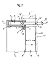
- the household appliance 1 comprises a front door 4 with a front surface 5, an upper edge 6, a lower edge 7 and lateral edges 8.
- a front panel cover 9 On the front surface 5 of the front door 4 is a front panel cover 9, which may be a so-called furniture panel attached.
- the signal light 11 is radiated and transmitted by means of the light guide 12 to the front side 13 of the front panel 9, so that the operating state of the household appliance 1 even when the front door 4 is verifiable.
- the lateral edge 8 of the front door 4 of the household appliance 1 comprises an optical operating display 10 with a light-emitting diode 20 which emits a signal light 11 in the direction perpendicular to the lateral edge 8.
- a bracket 21 is mounted as a fixing device, with a recess 22 at the position of the optical operating display 10.
- the bracket 21 includes a light guide 23, in which the signal light 11 couples through the recess 22 therethrough. This light guide 23 is in the bracket 21 parallel to the lateral edge 8 relative to the optical operating display 10 displaceable and fixable with a countersunk screw 24 in the bracket 21.
- the light guide 23 For a front panel 9 with a thickness of 25, the light guide 23 is moved so that its end face terminates in a position 26 with the front side 13 of the front panel device 9. In this way, the Lichtleitweg 27 is adapted to the thickness 25 of the front panel 9 device.
- the light guide 23 For a front panel 9 'with a thickness 25', the light guide 23 is moved so that its end face at a position 26 'with the front side 13' of the front panel 9 'completes. In this way, the Lichtleitweg 27 'is adapted to the thickness 25' of the front panel 9 '.
- the light guide 23 comprises an oblique light-reflecting surface which, depending on the thickness 25 or 25 'of the front panel 9 or 9' at the position 28 or 28 'is located. In this way, for different strengths 25 and 25 'of the front panel 9 or 9 'ensures that the reflected signal light 29 or 29' is reflected at right angles in the direction of the front side 13 or 13 'of the front panel 9 or 9' and is clearly visible there.
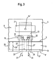
- the side edge 8 of the front door 4 of the household appliance 1 can be seen, which includes the optical power indicator 10, with a red light emitting diode 30, which emits a red signal light 31 and in the illustrated embodiment, the operating state indicates ON and with a green light emitting diode 32, which emits a green signal light 33 and the operating state OFF signals in the illustrated embodiment.
- the emitted from the light emitting diodes 30 and 32 signal light 31 and 33 coupled as described in Figure 2 in the disc-shaped light guide 23 and is guided by this to the front 13 and 13 'of the front panel 9 or 9'.
- the adaptation of the Lichtleitweges 27 and 27 'of the displaceable light guide 23 to the various thicknesses 25 and 25' of the front panel 9 or 9 ' is carried out as described in Figure 2.
- the signal light 31 or the signal light 33 is then visible on the front side 13 or 13 'of the front panel 9 or 9'.
- the front door 4 of the household appliance 1 when the front door 4 of the household appliance 1 is closed, it can at least be determined by a user whether the household appliance 1 is switched on or off. This is particularly advantageous when the household appliance 1 is a dishwasher, since accidental opening of the front door 4 in the switched-on operating state A in this case can lead to water leakage.
- the same light guide 23 can be used for signaling the different operating states ON, OFF, since the different operating states ON, OFF can be distinguished on account of the different colors of the signal light 31, 33.
- the optical operating display 10 for the display of several operating states may comprise a plurality of light emitting diodes with different colors. Also for the operating states ON and OFF, a color selection is not limited to red and green. Instead of LEDs, other bulbs, such as light bulbs can be used.
- FIG. 4 shows a further embodiment of the invention, in which a front door 4 of the household appliance 1 comprises the optical operating display.
- the front door 4 of the household appliance 1 comprises, outside the edges 6, 7, 8, an optical operating display 10 'with a light-emitting diode 20', which emits a signal light 40 in the direction of the lateral edge 8 of the front door 4.
- a first part of the light guide 41 is flush so arranged that the signal light 40 is transferable from the optical operating display 10' to the side edge 8 of the front door 4.
- This first part of the light guide 41 may also consist of a bundle of glass or plastic fibers.
- a second part of the light guide 42 is slidably disposed at a right angle to the first part of the light guide 41.
- This second part of the light guide 42 comprises an oblique light-reflecting surface 43, so that the signal light 40 is reflected by this surface 43 in the direction of the front side 13 of the front panel 9.
- the second part of the light guide 42 passes the reflected signal light 44 over the front panel 9, so that the reflected signal light 44 is visible on the front side 13 of the front panel 9.
- the second part of the light guide 42 is displaceable relative to the first part of the light guide 41 in order to allow the adaptation of the Lichtleitweges 45 to different strengths of the front panel 9 as described in Figure 2. This ensures that a sufficiently large area of the second part of the light guide 42 is visible to the user, so that the signal light 44 can be well recognized.
- the arrangement of the first part of the light guide 41 and the second part of the light guide 42 described above is also at the lower edge 7 and upper edge 6 of the front door 4 providable.
- the first part of the light guide 41 can consist of either a rigid rod-shaped or cylindrical light guide or else a bundle of glass fiber or plastic fibers.
- the first part of the light guide 41 can be curved, whereby the signal light 40 can also be directed from positions of the optical operating display 10 'to the edges 6, 7, 8, which are difficult to access with rigid light guides 41 are.
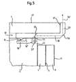
- FIG. 5 shows a further embodiment of the invention, in which a housing 50 of the household appliance 1 comprises the optical operating display.
- the housing 50 of the household appliance 1 comprises on the front side 51 of the household appliance 1 below the worktop 3 an optical operating display 10 "with a light-emitting diode 20" which emits a signal light 52 in the direction of the worktop 3.
- Below the worktop 3 is a parallel to the worktop 3 slidable light guide 53 to which the Lichtleitweg, analog to Figure 2, can be adapted to the width of the worktop 3.
- the displaceable light guide 53 is fixed in the selected position.
- the signal light 52 emitted by the optical operating display 10 "couples transversely into the displaceable optical waveguide 53, where it is reflected at a first oblique light-reflecting surface 55 at a right angle, so that the reflected signal light 56 propagates parallel to the work surface 3 in the displaceable optical waveguide 53
- the reflected signal light 56 is guided by the displaceable light guide 53 over the front door 4 of the household appliance 1 and across the front panel 9 towards the front side 13 of the front panel 9.
- the light guide 53 comprises the worktop 3 at its end face 57 at a right angle, the reflected signal light 56 is reflected at a second oblique light-reflecting surface 58 of the light guide 53 perpendicular to the surface 59 of the work surface 3, so that the double-reflected signal light 56 'is clearly visible.
- FIG. 6 shows a further embodiment of the invention, in which a front panel 9 comprises a light guide 63 with a projection length 68 for adapting the light guide path.
- the front door 4 of the household appliance 1 comprises on its front surface 5 behind the front panel 9, a controller 60 with an optical operating display 10 '' ', which in turn comprises a light emitting diode 20' '', which emits a signal light 61.
- the device front panel 9 has at the position of the optical operating display 10 '' 'as a through hole to a front to the front side 13 of the front panel 9 continuous bore 62, which is in particular cylindrical and which comprises the movable light guide 63.
- the displaceable light guide 63 is fixed by two clamps 64 and 64 'of the fixing device 65 flush with the optical operating indicator 10'''.
- An advantage of this design is that here too the length of the Lichtleitweges to the strength of the front panel device 9 is adaptable, since the light guide 63 has a corresponding projection length 68, by which he relative to the front panel 9 is slidable.
- the light guide 63 can be easily formed by a piece of cylindrical glass or plastic, whereby the light guide 63 is very inexpensive.
- a plurality of optical operating displays 10 "'are present on the front door 4 of the household appliance 1 or if the optical operating display comprises a plurality of light emitting diodes 20"' in order to signal different operating states the embodiment described above can be present multiple times.
- a plurality of displaceable optical fibers 63 may be provided for the transmission of signal light belonging to different operating states.
- these displaceable optical fibers 63 can be designed to distinguish the different operating states in different colors.
- the bore 62 can also be designed so that it comprises a plurality of optical fibers 63, which are arranged side by side and / or one below the other.
- the visibility of the signal light of at least one optical operating display 10 is substantially improved.
Abstract
Description
Die Erfindung betrifft ein Haushaltgerät, insbesondere ein Einbau-Haushaltgerät, mit wenigstens einer optischen Betriebsanzeige, die durch wenigstens ein Abdeckelement abdeckbar ist, wobei wenigstens ein Lichtleiter an die optische Betriebsanzeige zur Übertragung wenigstens eines abgestrahlten Signallichts angekoppelt ist.The invention relates to a household appliance, in particular a built-in domestic appliance, with at least one optical operating display, which can be covered by at least one cover, wherein at least one optical fiber is coupled to the optical operating display for transmitting at least one radiated signal light.
Es sind verschiedene Haushaltgeräte bekannt, wie beispielsweise Küchen-Haushaltgeräte, die im wesentlichen Herde, Kältegeräte und Geschirrspülmaschinen umfassen. Insbesondere bei Kältegeräten und bei Geschirrspülmaschinen gibt es sogenannte vollintegrierbare Haushaltgeräte, deren gesamte Frontfläche mit einer Gerätefrontverkleidung versehen ist, welche an umgebende Möbelfronten angepasst sein kann. Bei einem vollintegrierbaren Haushaltgerät besteht das Problem, dass eine optische Betriebsanzeige, bei einer geschlossenen Vordertür des vollintegrierbaren Haushaltgeräts durch die Gerätefrontverkleidung verborgen ist, so dass der Betriebszustand des vollintegrierbaren Haushaltgeräts nicht überprüfbar ist.There are various household appliances known, such as kitchen appliances, which essentially include stoves, refrigerators and dishwashers. Especially in refrigerators and dishwashers, there are so-called fully integrated household appliances, the entire front surface is provided with a front panel, which can be adapted to surrounding furniture fronts. In a fully integrated household appliance, the problem is that an optical power indicator, is hidden by the front panel of the device with a closed front door of fully integrated household appliance, so that the operating state of the fully integrated household appliance is not verifiable.
Aus EP 0 691 100 A1 ist ein Einbau-Haushaltgerät mit einem Gehäuse und einer Vordertür bekannt, wobei an einem oberen Rand der Vordertür eine Leuchtsignaleinrichtung vorgesehen ist, welche einen bestimmten Betriebszustand des Geräts anzeigt und welche bei geschlossener Vordertür verborgen ist. Dort sind zwischen dem oberen Rand der Vordertür und einer parallel zu diesem Rand verlaufenden Fläche Mittel vorgesehen, die ein von der Leuchtsignaleinrichtung abgestrahltes Licht in Richtung der Vorderseite der Vordertür übertragen.From EP 0 691 100 A1 a built-in domestic appliance with a housing and a front door is known, wherein a light signal device is provided on an upper edge of the front door, which indicates a specific operating state of the device and which is hidden when the front door is closed. There are provided between the upper edge of the front door and a plane extending parallel to this edge means, which transmit a radiated from the flare light device toward the front of the front door.
In DE 100 22 206 C2 ist eine einbaufähige Geschirrspülmaschine mit einer schwenkbaren Gerätetür beschrieben, die auf ihrer oberen Stirnfläche eine optische Betriebsanzeige mit einer oder mehreren Lichtquellen aufweist, welche bei geschlossener Gerätetür von einer oben auf der Geschirrspülmaschine aufliegenden Arbeitsplatte überdeckt werden. Dort ist ein Lichtleiter mit einem an der Arbeitsplattenunterseite über der Gerätetür lagefixierten Wrasenschutzelement verbunden, welcher das Signallicht der überdeckten optischen Betriebsanzeige zur Gerätefrontseite lenkt.DE 100 22 206 C2 describes a built-in dishwasher with a pivotable appliance door, which has on its upper end face an optical operating display with one or more light sources which are covered with a closed appliance door by a worktop resting on top of the dishwasher. There, a light guide is connected to a position fixed to the worktop base over the door fume protection element, which directs the signal light of the overlaid optical operating indicator to the front of the device.
Der Nachteil der in EP 0 691 100 A1 und in DE 100 22 206 C2 beschriebenen Einrichtungen besteht darin, dass das Signallicht im Lichtleiter für einen Benutzer, der vor dem Einbau-Haushaltsgerät bzw. der Geschirrspülmaschine steht schlecht sichtbar ist, da sich der Lichtleiter in einem Spalt zwischen Arbeitsplattenunterseite und Gerätetürrand befindet und von oben von der Arbeitsplatte abgedeckt wird. Insbesondere wird ein Erkennen des Signallichts bei Verwendung einer Gerätefrontverkleidung großer Stärke erschwert, da auf diese Weise der Lichtleiter zusätzlich von unten durch die Gerätefrontverkleidung abgedeckt wird.The disadvantage of the devices described in EP 0 691 100 A1 and in DE 100 22 206 C2 is that the signal light in the light guide is poorly visible to a user standing in front of the built-in domestic appliance or the dishwasher because the light guide is in a gap between worktop underside and door edge and is covered from above by the worktop. In particular, detection of the signal light when using a device front panel of great strength is made more difficult since in this way the light conductor is additionally covered from below by the front panel of the device.
Der Erfindung liegt die Aufgabe zugrunde, für ein Haushaltgerät, insbesondere ein Einbau-Haushaltgerät, die Sichtbarkeit des Signallichts wenigstens einer optischen Betriebsanzeige zu verbessern.The invention is based on the object for a household appliance, in particular a built-in household appliance, to improve the visibility of the signal light at least one optical operating indicator.
Diese Aufgabe wird bei einem Haushaltgerät der eingangs genannten Art dadurch gelöst, dass der Lichtleiter derart ausgebildet ist, dass sein Lichtleitweg an die Stärke des Abdeckelements anpassbar ist.This object is achieved in a household appliance of the type mentioned above in that the light guide is designed such that its Lichtleitweg is adaptable to the strength of the cover.
Dadurch dass der Lichtleitweg des Lichtleiters an die Stärke des Abdeckelements anpassbar ist, wird auf einfache Weise die Sichtbarkeit des vom Lichtleiter übertragenen Signallichts für einen Benutzer sichergestellt, da auch bei Abdeckelementen besonderer Stärke ein genügend großer Bereich des Lichtleiters frei sichtbar bleibt.The fact that the Lichtleitweg of the light guide is adaptable to the strength of the cover, the visibility of the signal transmitted from the light guide signal light is ensured for a user in a simple way, since even with cover elements of particular strength, a sufficiently large area of the light guide remains freely visible.
Nach einer bevorzugten Ausführungsform der Erfindung ist zur Anpassung des Lichtleitweges an die Stärke des Abdeckelements der Lichtleiter relativ zur optischen Betriebsanzeige verschiebbar.According to a preferred embodiment of the invention, the light guide is displaceable relative to the optical operating display to adapt the Lichtleitweges to the strength of the cover.
Nach einer weiteren bevorzugten Ausführungsform der Erfindung ist zur Anpassung des Lichtleitweges an die Stärke des Abdeckelements bei dem Lichtleiter eine Überstandslänge vorgesehen, um die der Lichtleiter relativ zum Abdeckelement verschiebbar ist. Mit dieser Maßnahme wird der Vorteil erzielt, dass nur ein Lichtleiter einer einzigen Länge und nicht Lichtleiter verschiedener Länge zusammen mit dem Haushaltgerät ausgeliefert werden müssen, die ansonsten nötig wären, um dem Benutzer eine Auswahl des Lichtleiters zu ermöglichen, der die passende Länge zu dem von ihm verwendeten Abdeckelement aufweist. Auf diese Art und Weise vereinfacht sich auch die Lagerhaltung für das Haushaltgerät, da nur Lichtleiter eines Typs vorrätig zu halten sind und nicht Lichtleiter unterschiedlicher Längen.According to a further preferred embodiment of the invention, a projection length is provided to adapt the Lichtleitweges to the thickness of the cover at the light guide, by which the light guide is displaceable relative to the cover. With this measure, the advantage is achieved that only a light guide of a single length and not light guides of different lengths must be delivered together with the household appliance, which would otherwise be necessary to allow the user a selection of the light guide, the appropriate length to that of Having him used cover. In this way, also simplifies the storage for the Household appliance, since only light guides of one type are to be kept in stock and not light guides of different lengths.
In einer nächsten Weiterbildung ist die optische Betriebsanzeige derart ausgebildet, dass zumindest die Betriebszustände des ein- und/oder ausgeschalteten Haushaltgeräts signalisierbar sind.In a next development, the optical operating display is designed such that at least the operating states of the switched on and / or off the household appliance can be signaled.
Dadurch kann bei geschlossener Vordertür des Haushaltgeräts zumindest festgestellt werden, ob das Haushaltgerät ein- oder ausgeschaltet ist. Dies ist besonders bei Geschirrspülmaschinen vorteilhaft, da ein versehentliches Öffnen der Vordertür im eingeschalteten Zustand dazu führen kann, dass Wasser austritt.As a result, when the front door of the household appliance is closed, it can at least be determined whether the household appliance is switched on or off. This is particularly advantageous in dishwashers, as accidental opening of the front door when switched on can cause water to escape.
Nach einer vorteilhaften Ausführungsform der Erfindung ist die optische Betriebsanzeige derart ausgebildet, dass für unterschiedliche Betriebszustände Signallicht unterschiedlicher Farbe abstrahlbar ist. Auf diese Weise kann für eine Übertragung des Signallichts der unterschiedlichen Betriebszustände derselbe Lichtleiter verwendet werden, da die unterschiedlichen Betriebszustände aufgrund der unterschiedlichen Farben des Signallichts unterschieden werden können.According to an advantageous embodiment of the invention, the optical operating display is designed such that signal light of different color can be emitted for different operating states. In this way, the same optical fiber can be used for a transmission of the signal light of the different operating states, since the different operating states can be distinguished due to the different colors of the signal light.
Weitere Merkmale der Erfindung und vorteilhafte Ausführungsformen der Erfindung sind in den Unteransprüchen gekennzeichnet.Further features of the invention and advantageous embodiments of the invention are characterized in the subclaims.
Mit der Erfindung ist bei einem Haushaltgerät, insbesondere bei einem Einbau-Haushaltgerät, die Sichtbarkeit des Signallichts wenigstens einer optischen Betriebsanzeige wesentlich verbessert.With the invention, in a domestic appliance, in particular in a built-in household appliance, the visibility of the signal light at least one optical operating indicator is substantially improved.
Die Erfindung und ihre Weiterbildungen werden nachfolgend anhand von Zeichnungen näher erläutert:The invention and its developments are explained in more detail below with reference to drawings:
Es zeigen
Figur 1- eine schematische Seitenansicht eines Haushaltgeräts mit einer Arbeitsplatte und einer Gerätefrontverkleidung als Abdeckelemente,
Figur 2- eine schematische Schnittdarstellung eines Teils des Haushaltgeräts nach
Figur 1 zur Veranschaulichung einer Anpassung eines Lichtleitweges an unterschiedliche Stärken der Gerätefrontverkleidung, Figur 3- eine schematische Draufsicht eines Teils des Haushaltgeräts nach
Figur 2, - Figur 4
- eine schematische Schnittdarstellung eines Teils des Haushaltgeräts nach
Figur 1 zur Veranschaulichung einer Position eines Lichtleiters, wenn eine Vordertür des Haushaltgeräts die optische Betriebsanzeige umfasst, Figur 5- eine schematische Schnittdarstellung eines Teils des Haushaltgeräts nach
Figur 1 zur Veranschaulichung einer Position eines Lichtleiters, wenn das Gehäuse des Haushaltgeräts die optische Betriebsanzeige umfasst und Figur 6- eine schematische Schnittdarstellung eines Teils des Haushaltgeräts nach
Figur 1 mit einer Gerätefrontverkleidung, die einen Lichtleiter mit einer Überstandslänge zur Anpassung des Lichtleitweges umfasst.
- FIG. 1
- a schematic side view of a household appliance with a worktop and a front panel as cover elements,
- FIG. 2
- 1 is a schematic sectional view of part of the household appliance according to FIG. 1 for illustrating an adaptation of an optical path to different thicknesses of the front panel of the appliance;
- FIG. 3
- FIG. 2 shows a schematic top view of part of the household appliance according to FIG. 2,
- FIG. 4
- a schematic sectional view of a portion of the household appliance of Figure 1 illustrating a position of a light guide when a front door of the household appliance includes the optical status indicator,
- FIG. 5
- a schematic sectional view of a portion of the household appliance according to Figure 1 for illustrating a position of a light guide, when the housing of the household appliance includes the optical status indicator and
- FIG. 6
- a schematic sectional view of a portion of the household appliance of Figure 1 with a front panel device that includes a light guide with a protrusion length for adjusting the Lichtleitweges.
Das in Figur 1 in einer schematischen Seitenansicht gezeigte Haushaltgerät 1, welches insbesondere eine Geschirrspülmaschine oder ein Kühlgerät ist, ruht auf einem Sockel 2 und wird von einer Arbeitsplatte 3 abgedeckt. Das Haushaltgerät 1 umfasst eine Vordertür 4 mit einer Frontfläche 5, einem oberen Rand 6, einem unteren Rand 7 und seitlichen Rändern 8. An der Frontfläche 5 der Vordertür 4 ist als Abdeckelement eine Gerätefrontverkleidung 9, die eine sogenannte Möbelplatte sein kann, angebracht.The
Von der optischen Betriebsanzeige 10, die sich an dem seitlichen Rand 8 der Vordertür 4 befindet, wird das Signallicht 11 abgestrahlt und mit Hilfe des Lichtleiters 12 an die Vorderseite 13 der Gerätefrontverkleidung 9 übertragen, so dass der Betriebszustand des Haushaltgeräts 1 auch bei geschlossener Vordertür 4 überprüfbar ist.From the
In Figur 2 ist die eine Anpassung eines Lichtleitweges an unterschiedliche Stärken der Gerätefrontverkleidung veranschaulicht.In Figure 2, an adaptation of a Lichtleitweges is illustrated to different strengths of the front panel.
Der seitliche Rand 8 der Vordertür 4 des Haushaltgeräts 1 umfasst eine optische Betriebsanzeige 10 mit einer Leuchtdiode 20, die ein Signallicht 11 in Richtung senkrecht zu dem seitlichen Rand 8 abstrahlt. Auf dem seitlichen Rand 8 ist als Fixiervorrichtung ein Bügel 21 montiert, mit einer Aussparung 22 an der Position der optischen Betriebsanzeige 10. Der Bügel 21 umfasst einen Lichtleiter 23, in den das Signallicht 11 durch die Aussparung 22 hindurch einkoppelt. Dieser Lichtleiter 23 ist in dem Bügel 21 parallel zu dem seitlichen Rand 8 relativ zur optischen Betriebsanzeige 10 verschiebbar und mit einer Senkkopfschraube 24 in dem Bügel 21 fixierbar.The
Für eine Gerätefrontverkleidung 9 mit einer Stärke 25, wird der Lichtleiter 23 so verschoben, dass seine Stimfläche in einer Position 26 mit der Vorderseite 13 der Gerätefrontverkleidung 9 abschließt. Auf diese Weise wird der Lichtleitweg 27 an die Stärke 25 der Gerätefrontverkleidung 9 angepasst. Für eine Gerätefrontverkleidung 9' mit einer Stärke 25', wird der Lichtleiter 23 so verschoben, dass seine Stirnfläche an einer Position 26' mit der Vorderseite 13' der Gerätefrontverkleidung 9' abschließt. Auf diese Weise wird der Lichtleitweg 27' an die Stärke 25' der Gerätefrontverkleidung 9' angepasst.For a
Weiterhin umfasst der Lichtleiter 23 eine schräge lichtreflektierende Fläche, die sich je nach Stärke 25 oder 25' der Gerätefrontverkleidung 9 oder 9' an der Position 28 bzw. 28' befindet. Auf diese Weise ist für verschiedene Stärken 25 bzw. 25' der Gerätefrontverkleidung 9 bzw. 9' gewährleistet, dass das reflektierte Signallicht 29 bzw. 29' rechtwinklig in Richtung der Vorderseite 13 bzw. 13' der Gerätefrontverkleidung 9 bzw. 9' reflektiert wird und dort gut sichtbar ist.Furthermore, the
In der Draufsicht in Figur 3 ist der seitliche Rand 8 der Vordertür 4 des Haushaltgeräts 1 zu erkennen, der die optische Betriebsanzeige 10 umfasst, mit einer roten Leuchtdiode 30, die ein rotes Signallicht 31 abstrahlt und im gezeigten Ausführungsbeispiel den Betriebszustand EIN signalisiert und mit einer grünen Leuchtdiode 32, die ein grünes Signallicht 33 abstrahlt und im gezeigten Ausführungsbeispiel den Betriebszustand AUS signalisiert.In the plan view in Figure 3, the
Das von den Leuchtdioden 30 und 32 abgestrahlte Signallicht 31 und 33 koppelt wie in Figur 2 beschrieben in den scheibenförmigen Lichtleiter 23 ein und wird von diesem bis zur Vorderseite 13 bzw. 13' der Gerätefrontverkleidung 9 bzw. 9' geleitet. Die Anpassung des Lichtleitweges 27 bzw. 27' des verschiebbaren Lichtleiters 23 an die verschiedenen Stärken 25 bzw. 25' der Gerätefrontverkleidung 9 bzw. 9' erfolgt wie in Figur 2 beschrieben. An der Vorderseite 13 bzw. 13' der Gerätefrontverkleidung 9 bzw. 9' ist dann je nach Betriebszustand EIN oder AUS das Signallicht 31 oder das Signallicht 33 sichtbar.The emitted from the
Auf diese Weise kann bei geschlossener Vordertür 4 des Haushaltgeräts 1 von einem Benutzer zumindest festgestellt werden, ob das Haushaltgerät 1 ein- oder ausgeschaltet ist. Dies ist besonders vorteilhaft, wenn das Haushaltgerät 1 eine Geschirrspülmaschine ist, da ein versehentliches Öffnen der Vordertür 4 im eingeschalteten Betriebszustand EIN in diesem Fall dazu führen kann, dass Wasser austritt.In this way, when the front door 4 of the
Durch die Verwendung von Leuchtdioden 30, 32 unterschiedlicher Farbe kann für die Signalisierung der unterschiedlichen Betriebszustände EIN, AUS derselbe Lichtleiter 23 verwendet werden, da die unterschiedlichen Betriebszustände EIN, AUS aufgrund der unterschiedlichen Farben des Signallichts 31, 33 unterschieden werden können. Insbesondere kann die optische Betriebsanzeige 10 für die Anzeige mehrerer Betriebszustände mehrere Leuchtdioden mit verschiedenen Farben umfassen. Auch für die Betriebszustände EIN und AUS ist eine Farbauswahl nicht auf rot und grün beschränkt. Statt Leuchtdioden können auch andere Leuchtmittel, wie beispielsweise Glühbirnen verwendet werden.By using light-emitting
In Figur 4 ist eine weitere Ausführungsform der Erfindung gezeigt, bei der eine Vordertür 4 des Haushaltgeräts 1 die optische Betriebsanzeige umfasst. Die Vordertür 4 des Haushaltgeräts 1 umfasst außerhalb der Ränder 6, 7, 8 eine optische Betriebsanzeige 10' mit einer Leuchtdiode 20', die ein Signallicht 40 in Richtung des seitlichen Randes 8 der Vordertür 4 abstrahlt. An der optischen Betriebsanzeige 10' ist ein erster Teil des Lichtleiters 41 bündig derart angeordnet ist, dass das Signallicht 40 von der optischen Betriebsanzeige 10' bis zu dem seitlichen Rand 8 der Vordertür 4 übertragbar ist. Dieser erste Teil des Lichtleiters 41 kann auch aus einem Bündel Glas- oder Kunststofffasern bestehen.FIG. 4 shows a further embodiment of the invention, in which a front door 4 of the
Auf dem seitlichen Rand 8 der Vordertür 4 ist ein zweiter Teil des Lichtleiters 42 in einem Rechtenwinkel zu dem ersten Teil des Lichtleiters 41 verschiebbar angeordnet. Dieser zweite Teil des Lichtleiters 42 umfasst eine schräge lichtreflektierende Fläche 43, so dass das Signallicht 40 von dieser Fläche 43 in Richtung der Vorderseite 13 der Gerätefrontverkleidung 9 reflektiert wird. Der zweite Teil des Lichtleiters 42 leitet das reflektierte Signallicht 44 über die Gerätefrontverkleidung 9 hinweg, so dass das reflektierte Signallicht 44 an der Vorderseite 13 der Gerätefrontverkleidung 9 sichtbar ist.On the
Der zweite Teil des Lichtleiters 42 ist relativ zu dem ersten Teil des Lichtleiters 41 verschiebbar, um wie in Figur 2 beschrieben, die Anpassung des Lichtleitweges 45 an unterschiedliche Stärken der Gerätefrontverkleidung 9 zu ermöglichen. Dadurch wird sichergestellt, dass ein genügend großer Bereich des zweiten Teils des Lichtleiters 42 für den Benutzer sichtbar ist, so dass das Signallicht 44 gut erkannt werden kann.The second part of the
Strahlt die optische Betriebsanzeige 10' das Signallicht 40 in Richtung auf den unteren Rand 7 oder den oberen Rand 6 der Vordertür 4 ab, so ist die oben beschriebene Anordnung des ersten Teils des Lichtleiters 41 und des zweiten Teils des Lichtleiters 42 auch an dem unteren Rand 7 bzw. oberen Rand 6 der Vordertür 4 vorsehbar. Insbesondere kann der erste Teil des Lichtleiters 41 entweder aus einem starren stab- oder zylinderförmigen Lichtleiter oder aber aus einem Bündel von Glasfaser bzw. Kunststofffasem bestehen. Da die Fasern biegsam sind, kann der erste Teil des Lichtleiters 41 in diesem Fall gekrümmt werden, wodurch das Signallicht 40 auch von Positionen der optischen Betriebsanzeige 10' an die Ränder 6, 7, 8 geleitet werden kann, die mit starren Lichtleitern 41 schwer zugänglich sind.If the optical operating display 10 'emits the
In Figur 5 ist eine weitere Ausführungsform der Erfindung gezeigt, bei der eine Gehäuse 50 des Haushaltgeräts 1 die optische Betriebsanzeige umfasst. Das Gehäuse 50 des Haushaltgeräts 1 umfasst an der Vorderseite 51 des Haushaltgeräts 1 unterhalb der Arbeitsplatte 3 eine optische Betriebsanzeige 10" mit einer Leuchtdiode 20", die ein Signallicht 52 in Richtung der Arbeitsplatte 3 abstrahlt. Unterhalb der Arbeitsplatte 3 befindet sich ein parallel zur Arbeitsplatte 3 verschiebbarer Lichtleiter 53 mit dem der Lichtleitweg, anlog zu Figur 2, an die Breite der Arbeitsplatte 3 angepasst werden kann. Mit der Klemme 54 der Fixiervorrichtung 55 wird der verschiebbare Lichtleiter 53 in der gewählten Position fixiert.FIG. 5 shows a further embodiment of the invention, in which a
Das von der optischen Betriebsanzeige 10" abgestrahlte Signallicht 52 koppelt quer in den verschiebbaren Lichtleiter 53 ein, wird dort an einer ersten schrägen lichtreflektierenden Fläche 55 in einem rechten Winkel reflektiert, so dass sich das reflektierte Signallicht 56 parallel zur Arbeitsplatte 3 im verschiebbaren Lichtleiter 53 ausbreitet. Das reflektierte Signallicht 56 wird von dem verschiebbaren Lichtleiter 53 über die Vordertür 4 des Haushaltgeräts 1 und über die Gerätefrontverkleidung 9 hinweg in Richtung Vorderseite 13 der Gerätefrontverkleidung 9 geleitet. Der Lichtleiter 53 umfasst die Arbeitsplatte 3 an deren Stimfläche 57 in einem rechten Winkel derart, dass das reflektierte Signallicht 56 an einer zweiten schrägen lichtreflektierenden Fläche 58 des Lichtleiters 53 senkrecht zur Oberfläche 59 der Arbeitsplatte 3 reflektiert wird, so dass das doppelt reflektierte Signallicht 56' gut sichtbar ist.The
In Figur 6 ist eine weitere Ausführungsform der Erfindung gezeigt, bei der eine Gerätefrontverkleidung 9 einen Lichtleiter 63 mit einer Überstandslänge 68 zur Anpassung des Lichtleitweges umfasst. Die Vordertür 4 des Haushaltgeräts 1 umfasst an ihrer Frontfläche 5 hinter der Gerätefrontverkleidung 9 eine Steuerung 60 mit einer optischen Betriebsanzeige 10''', die ihrerseits eine Leuchtdiode 20''' umfasst, die ein Signallicht 61 abstrahlt. Die Gerätefrontverkleidung 9 weist an der Position der optischen Betriebsanzeige 10''' als Durchgangsöffnung eine bis zur Vorderseite 13 der Gerätefrontverkleidung 9 durchgängige Bohrung 62 auf, die insbesondere zylinderförmig ausgeführt ist und die den verschiebbaren Lichtleiter 63 umfasst.FIG. 6 shows a further embodiment of the invention, in which a
Der verschiebbaren Lichtleiter 63 ist durch zwei Klemmen 64 und 64' der Fixiervorrichtung 65 bündig an der optischen Betriebsanzeige 10''' fixiert. Das von der Leuchtdiode 20''' abgestrahlte Signallicht 61 kann auf diese Weise direkt in den Lichtleiter 63 einkoppeln, wird an der lichtreflektierenden Fläche 66 in Richtung der Vorderseite 13 der Gerätefrontverkleidung 9 reflektiert und wird durch den Lichtleiter 63 an die Vorderseite 13 der Gerätefrontverkleidung 9 geleitet, so dass das reflektierte Signallicht 67 dort sichtbar ist.The displaceable
Ein Vorteil dieser Ausführung besteht darin, dass auch hier die Länge des Lichtleitweges an die Stärke der Gerätefrontverkleidung 9 anpassbar ist, da der Lichtleiter 63 über eine entsprechende Überstandslänge 68 verfügt, um die er relativ zur Gerätefrontverkleidung 9 verschiebbar ist. Darüber hinaus kann der Lichtleiter 63 einfach durch ein Stück zylinderförmiges Glas oder Kunststoff gebildet sein, wodurch der Lichtleiter 63 sehr kostengünstig ist.An advantage of this design is that here too the length of the Lichtleitweges to the strength of the
Sind an der Vordertür 4 des Haushaltgeräts 1 mehrere optische Betriebsanzeigen 10"' vorhanden oder umfasst die optische Betriebsanzeige mehrere Leuchtdioden 20"', um verschiedene Betriebszustände zu signalisieren, so kann die oben beschriebene Ausführung mehrfach vorhanden sein. Auf diese Weise können mehrere verschiebbare Lichtleiter 63 zur Übertragung von zu unterschiedlichen Betriebszuständen gehörendem Signallicht vorgesehen sein. Insbesondere können diese verschiebbaren Lichtleiter 63 zur Unterscheidung der verschiedenen Betriebszustände in unterschiedlichen Farben ausgestaltet sein. Darüber hinaus kann die Bohrung 62 auch so ausgestaltet sein, dass sie mehrere Lichtleiter 63 umfasst, die nebeneinander und/oder untereinander angeordnet sind.If a plurality of optical operating displays 10 "'are present on the front door 4 of the
Mit der Erfindung ist bei einem Haushaltgerät 1, insbesondere bei einem Einbau-Haushaltgerät, die Sichtbarkeit des Signallichts wenigstens einer optischen Betriebsanzeige 10 wesentlichverbessert.With the invention, in a
Claims (21)
- Domestic appliance, particularly built-in domestic appliance, with at least one optical operating display which can be covered by at least one cover element, wherein at least one optical waveguide is coupled to the optical operating display for transmission of at least one radiated signal light, wherein the optical waveguide (12, 23) is constructed in such a manner that its optical path (27, 27') is adaptable to the thickness of the cover element (3, 9), characterised in that the optical waveguide (23) is composed of at least two parts in such a manner that for adaptation of the optical path (27, 27') the second part (42) of the optical waveguide is displaceable relative to the first part (41) of the optical waveguide.
- Domestic appliance according to claim 1, characterised in that for adaptation of the optical path (27, 27') the optical waveguide (23) is displaceable relative to the optical operating display (10).
- Domestic appliance according to claim 1, characterised in that for adaptation of the optical path (27, 27') there is provided at the optical waveguide (23, 63) an excess length (68) by which the optical waveguide (23, 63) is displaceable relative to the cover element (3, 9).
- Domestic appliance according to claim 2 or 3, characterised in that a fixing device (21) by which the optical waveguide (23, 42) is fixable in a predeterminable displacement position is provided.
- Domestic appliance according to one of the preceding claims, characterised in that the cover element is formed by a front door (4) and/or an apparatus front cladding (9) arranged in front thereof and/or a worktop (3).
- Domestic appliance according to one of the preceding claims, characterised in that the optical waveguide (23, 42) is arranged in at least one of the edge regions (6, 7, 8) of the cover element (4, 9).
- Domestic appliance according to one of the preceding claims, characterised in that the optical waveguide (23, 42) is arranged outside the upper edge region (6) of the cover element (4, 9).
- Domestic appliance according to claim 1 to 5, characterised in that the coupling location of the optical waveguide (63, 41) to the operating display (10', 10"') is arranged behind the cover element (9).
- Domestic appliance according to claim 8, characterised in that at least one passage opening (52), which comprises at least one optical waveguide (63), is provided in the cover element (9).
- Domestic appliance according to claim 1 to 5, characterised in that the coupling location of the optical waveguide (53) to the optical operating display (10") is arranged within the housing (50) of the domestic appliance (1).
- Domestic appliance according to one of the preceding claims, characterised in that the optical waveguide (23, 41, 42, 63) is of rod-shaped, disc-shaped or cylindrical construction.
- Domestic appliance according to one of the preceding claims, characterised in that the optical waveguide (23, 41, 42, 63) is constructed to be rigid or flexible.
- Domestic appliance according to one of the preceding claims, characterised in that the optical waveguide (23, 42, 63) is arranged in such a manner that the signal light (11, 31, 33, 44, 67) is transmissible to the front side of the cover element (13).
- Domestic appliance according to one of the preceding claims, characterised in that the optical waveguide (23, 41, 42, 63) comprises at least one glass fibre.
- Domestic appliance according to one of the preceding claims, characterised in that the optical waveguide (23, 41, 42, 63) comprises at least one synthetic material fibre.
- Domestic appliance according to one of the preceding claims, characterised in that the optical operating display (10) is constructed in such a manner that at least the operational states (ON, OFF) of the switched-on and/or switched-off domestic appliance (1) can be signalled.
- Domestic appliance according to one of the preceding claims, characterised in that the optical operating display (10) comprises at least one light-emitting diode (20).
- Domestic appliance according to one of the preceding claims, characterised in that the optical operating display (10) is constructed in such a manner that signal light (31, 33) of different colour can be radiated for different operational states (ON, OFF).
- Domestic appliance according to one of the preceding claims, characterised in that several optical waveguides (63) for transmission of signal light (61, 31, 33) belonging to different operational states (ON, OFF) are provided.
- Domestic appliance according to one of the preceding claims, characterised in that optical conductors (63) of different colour are provided for the display of different operational states (ON, OFF).
- Domestic appliance according to one of the preceding claims, characterised in that the domestic appliance (1) is a dishwashing machine.
Applications Claiming Priority (3)
| Application Number | Priority Date | Filing Date | Title |
|---|---|---|---|
| DE10259764 | 2002-12-19 | ||
| DE10259764A DE10259764A1 (en) | 2002-12-19 | 2002-12-19 | Household appliance, in particular built-in household appliance |
| PCT/EP2003/013718 WO2004056256A1 (en) | 2002-12-19 | 2003-12-04 | Domestic appliance, in particular a built-in domestic appliance |
Publications (2)
| Publication Number | Publication Date |
|---|---|
| EP1575412A1 EP1575412A1 (en) | 2005-09-21 |
| EP1575412B1 true EP1575412B1 (en) | 2006-08-09 |
Family
ID=32477839
Family Applications (1)
| Application Number | Title | Priority Date | Filing Date |
|---|---|---|---|
| EP03813557A Expired - Lifetime EP1575412B1 (en) | 2002-12-19 | 2003-12-04 | Domestic appliance, in particular a built-in domestic appliance |
Country Status (8)
| Country | Link |
|---|---|
| US (1) | US7308186B2 (en) |
| EP (1) | EP1575412B1 (en) |
| CN (1) | CN100473321C (en) |
| AT (1) | ATE335432T1 (en) |
| AU (1) | AU2003296611A1 (en) |
| DE (2) | DE10259764A1 (en) |
| ES (1) | ES2270176T3 (en) |
| WO (1) | WO2004056256A1 (en) |
Families Citing this family (15)
| Publication number | Priority date | Publication date | Assignee | Title |
|---|---|---|---|---|
| DE102005047915A1 (en) | 2005-10-06 | 2007-04-12 | BSH Bosch und Siemens Hausgeräte GmbH | Indicator light arrangement for built-in domestic appliance, e.g. dishwasher, involves a reflecting sealing strip in gap between unit fronts |
| DE102005047914A1 (en) | 2005-10-06 | 2007-04-19 | BSH Bosch und Siemens Hausgeräte GmbH | Dishwasher, in particular domestic dishwasher with a controllable operating display |
| EP1702551A1 (en) * | 2006-03-31 | 2006-09-20 | V-Zug AG | Domestic appliance with decorative panel and optical display integrated therein |
| DE102006049396A1 (en) * | 2006-10-19 | 2008-04-24 | BSH Bosch und Siemens Hausgeräte GmbH | Household appliance with projection display |
| DE102008043270A1 (en) * | 2008-10-29 | 2010-05-06 | BSH Bosch und Siemens Hausgeräte GmbH | Light-guiding element for built-in furniture for e.g. laundry dryer, has fastening unit for fastening at door of furniture, where element guides light emitted from rear of door to front side of door |
| DE102008043350A1 (en) * | 2008-10-31 | 2010-05-06 | BSH Bosch und Siemens Hausgeräte GmbH | Display unit with adjustable display color |
| EP2363055A1 (en) | 2010-03-01 | 2011-09-07 | Electrolux Home Products Corporation N.V. | Projector and household appliance comprising such a projector |
| ITRN20100005A1 (en) * | 2010-03-02 | 2011-09-03 | Indesit Co Spa | APPLIANCE |
| JP5433599B2 (en) * | 2011-02-16 | 2014-03-05 | 京セラドキュメントソリューションズ株式会社 | Image forming apparatus |
| JP6047921B2 (en) | 2012-05-11 | 2016-12-21 | 株式会社リコー | Display device and image forming apparatus |
| DE102013208374B4 (en) * | 2013-05-07 | 2016-08-18 | Meiko Maschinenbau Gmbh & Co. Kg | Cleaning device with illuminated door handle |
| DE102015201324A1 (en) * | 2015-01-27 | 2016-07-28 | BSH Hausgeräte GmbH | Cooking appliance |
| CN106324953A (en) * | 2015-07-08 | 2017-01-11 | 博西华电器(江苏)有限公司 | Household electric appliance with display device |
| CN109307195A (en) * | 2017-07-26 | 2019-02-05 | 博西华电器(江苏)有限公司 | Refrigerating appliance |
| US11340853B2 (en) | 2020-04-01 | 2022-05-24 | Anova Applied Electronics, Inc. | Appliance handle with automatic shutoff of input interface elements |
Family Cites Families (12)
| Publication number | Priority date | Publication date | Assignee | Title |
|---|---|---|---|---|
| US2358425A (en) * | 1941-10-27 | 1944-09-19 | John J Leary | Warning signal for refrigerators and the like |
| US2737573A (en) | 1953-10-28 | 1956-03-06 | Gen Electric | Lighting means for automatic clothes washers |
| DE2907270A1 (en) | 1979-02-24 | 1980-09-04 | Licentia Gmbh | HOUSEHOLD APPLIANCE WITH A CABINET-SHAPED HOUSING |
| DE3737514A1 (en) * | 1987-11-05 | 1989-05-18 | Philips Patentverwaltung | LIGHT GUIDE FOR FRONT PANELS OF ELECTRICAL DEVICES |
| IT1266873B1 (en) * | 1994-07-06 | 1997-01-21 | Merloni Elettrodomestici Spa | HOUSEHOLD APPLIANCE APPARATUS OF THE INTEGRABLE TYPE |
| JPH10142426A (en) | 1996-11-15 | 1998-05-29 | Matsushita Electric Works Ltd | Light transmission member |
| DE10022206C2 (en) * | 2000-05-06 | 2002-06-13 | Miele & Cie | Dishwasher, in particular built-in dishwasher with an optical operating display |
| JP2002313181A (en) | 2001-04-18 | 2002-10-25 | Auto Network Gijutsu Kenkyusho:Kk | Operation panel device |
| ITPN20010089A1 (en) * | 2001-12-19 | 2003-06-19 | Electrolux Zanussi Elettrodome | HOUSEHOLD APPLIANCES, IN PARTICULAR DISHWASHER, WITH IMPROVED ACCESS DOOR. |
| ITPN20020007A1 (en) * | 2002-02-05 | 2003-08-05 | Electrolux Home Products Corpo | HOUSEHOLD APPLIANCES WITH LIGHTING SYSTEM |
| DE10259762A1 (en) * | 2002-12-19 | 2004-07-01 | BSH Bosch und Siemens Hausgeräte GmbH | Household appliance, in particular built-in household appliance |
| JP3838196B2 (en) * | 2002-12-24 | 2006-10-25 | ブラザー工業株式会社 | Electronics |
-
2002
- 2002-12-19 DE DE10259764A patent/DE10259764A1/en not_active Withdrawn
-
2003
- 2003-12-04 CN CNB200380109844XA patent/CN100473321C/en not_active Expired - Fee Related
- 2003-12-04 US US10/539,824 patent/US7308186B2/en not_active Expired - Fee Related
- 2003-12-04 AT AT03813557T patent/ATE335432T1/en not_active IP Right Cessation
- 2003-12-04 AU AU2003296611A patent/AU2003296611A1/en not_active Abandoned
- 2003-12-04 DE DE50304614T patent/DE50304614D1/en not_active Expired - Lifetime
- 2003-12-04 WO PCT/EP2003/013718 patent/WO2004056256A1/en not_active Application Discontinuation
- 2003-12-04 EP EP03813557A patent/EP1575412B1/en not_active Expired - Lifetime
- 2003-12-04 ES ES03813557T patent/ES2270176T3/en not_active Expired - Lifetime
Also Published As
| Publication number | Publication date |
|---|---|
| WO2004056256A1 (en) | 2004-07-08 |
| ATE335432T1 (en) | 2006-09-15 |
| DE10259764A1 (en) | 2004-07-08 |
| US20060280422A1 (en) | 2006-12-14 |
| US7308186B2 (en) | 2007-12-11 |
| ES2270176T3 (en) | 2007-04-01 |
| CN100473321C (en) | 2009-04-01 |
| EP1575412A1 (en) | 2005-09-21 |
| CN1750784A (en) | 2006-03-22 |
| DE50304614D1 (en) | 2006-09-21 |
| AU2003296611A1 (en) | 2004-07-14 |
Similar Documents
| Publication | Publication Date | Title |
|---|---|---|
| EP1581090B1 (en) | Built-in household appliance | |
| EP1575412B1 (en) | Domestic appliance, in particular a built-in domestic appliance | |
| EP2359738B1 (en) | Household device, in particular installed household device with a controllable operating display | |
| EP1576632B1 (en) | Optical operation indicator for a domestic appliance, in addition to domestic appliance, in particular a built-in domestic appliance | |
| EP2407852B1 (en) | Support for an operating device | |
| DE19655279B4 (en) | Laundry treatment or dishwasher | |
| DE102004062752A1 (en) | Integrated operating display element | |
| DE102009033538A1 (en) | Operating device for an electrical appliance | |
| EP1421893A1 (en) | Household appliance integrable into a row of furniture with a display device | |
| DE102006049396A1 (en) | Household appliance with projection display | |
| DE10239602B3 (en) | Optical signal system, for a railway shunting yard, has a green-emitting laser coupled to an optic fiber along at least part of the length of connecting cable, giving externally visible illumination | |
| DE102006033040A1 (en) | Display device for a motor vehicle with a substantially parallel light beam | |
| DE102004054732A1 (en) | Optical fiber arrangement for external rear view mirror of vehicle, has stretched optical fiber rod that is approximately parallel to edge of plate shaped optical fiber, and light source connected to front end of optical fiber rod | |
| DE4227468C2 (en) | Electrical switch unit, in particular for controlling air conditioning systems in motor vehicles | |
| DE10210161B4 (en) | Beverage maker, especially coffee maker | |
| EP1728026B2 (en) | Control panel for domestic refrigerator | |
| DE102017219044A1 (en) | Drink dispenser and refrigeration device with beverage dispenser | |
| DE102009000655B3 (en) | Household appliance, particularly baking oven for preparing food, has lighting device with light source for lighting cooking chamber of household appliance | |
| EP1790528A1 (en) | Outline illuminating device of a vehicle external handle | |
| DE102005040990A1 (en) | Mountable dishwasher for use in kitchen, has light conductor with several sections provided in the form of teeth for guiding light radiations from light source to front side of dishwasher | |
| EP2701031A2 (en) | Operating element and operating device | |
| DE69909158T2 (en) | Control panel unit for a household appliance | |
| EP2339602A1 (en) | Switching device and fibre optic cable | |
| EP1391904B1 (en) | Security and monitoring system for doors, windows or similar | |
| DE10155126B4 (en) | Optical signal transmitter, in particular in the control panel of a large household appliance |
Legal Events
| Date | Code | Title | Description |
|---|---|---|---|
| PUAI | Public reference made under article 153(3) epc to a published international application that has entered the european phase |
Free format text: ORIGINAL CODE: 0009012 |
|
| 17P | Request for examination filed |
Effective date: 20050719 |
|
| AK | Designated contracting states |
Kind code of ref document: A1 Designated state(s): AT BE BG CH CY CZ DE DK EE ES FI FR GB GR HU IE IT LI LU MC NL PT RO SE SI SK TR |
|
| AX | Request for extension of the european patent |
Extension state: AL LT LV MK |
|
| GRAP | Despatch of communication of intention to grant a patent |
Free format text: ORIGINAL CODE: EPIDOSNIGR1 |
|
| DAX | Request for extension of the european patent (deleted) | ||
| GRAS | Grant fee paid |
Free format text: ORIGINAL CODE: EPIDOSNIGR3 |
|
| GRAA | (expected) grant |
Free format text: ORIGINAL CODE: 0009210 |
|
| AK | Designated contracting states |
Kind code of ref document: B1 Designated state(s): AT BE BG CH CY CZ DE DK EE ES FI FR GB GR HU IE IT LI LU MC NL PT RO SE SI SK TR |
|
| PG25 | Lapsed in a contracting state [announced via postgrant information from national office to epo] |
Ref country code: RO Free format text: LAPSE BECAUSE OF FAILURE TO SUBMIT A TRANSLATION OF THE DESCRIPTION OR TO PAY THE FEE WITHIN THE PRESCRIBED TIME-LIMIT Effective date: 20060809 Ref country code: FI Free format text: LAPSE BECAUSE OF FAILURE TO SUBMIT A TRANSLATION OF THE DESCRIPTION OR TO PAY THE FEE WITHIN THE PRESCRIBED TIME-LIMIT Effective date: 20060809 Ref country code: SI Free format text: LAPSE BECAUSE OF FAILURE TO SUBMIT A TRANSLATION OF THE DESCRIPTION OR TO PAY THE FEE WITHIN THE PRESCRIBED TIME-LIMIT Effective date: 20060809 Ref country code: CZ Free format text: LAPSE BECAUSE OF FAILURE TO SUBMIT A TRANSLATION OF THE DESCRIPTION OR TO PAY THE FEE WITHIN THE PRESCRIBED TIME-LIMIT Effective date: 20060809 Ref country code: SK Free format text: LAPSE BECAUSE OF FAILURE TO SUBMIT A TRANSLATION OF THE DESCRIPTION OR TO PAY THE FEE WITHIN THE PRESCRIBED TIME-LIMIT Effective date: 20060809 Ref country code: NL Free format text: LAPSE BECAUSE OF FAILURE TO SUBMIT A TRANSLATION OF THE DESCRIPTION OR TO PAY THE FEE WITHIN THE PRESCRIBED TIME-LIMIT Effective date: 20060809 Ref country code: IE Free format text: LAPSE BECAUSE OF FAILURE TO SUBMIT A TRANSLATION OF THE DESCRIPTION OR TO PAY THE FEE WITHIN THE PRESCRIBED TIME-LIMIT Effective date: 20060809 |
|
| REG | Reference to a national code |
Ref country code: GB Ref legal event code: FG4D Free format text: NOT ENGLISH |
|
| REG | Reference to a national code |
Ref country code: CH Ref legal event code: NV Representative=s name: SIEMENS SCHWEIZ AG Ref country code: CH Ref legal event code: EP |
|
| REG | Reference to a national code |
Ref country code: IE Ref legal event code: FG4D Free format text: LANGUAGE OF EP DOCUMENT: GERMAN |
|
| GBT | Gb: translation of ep patent filed (gb section 77(6)(a)/1977) |
Effective date: 20060818 |
|
| REF | Corresponds to: |
Ref document number: 50304614 Country of ref document: DE Date of ref document: 20060921 Kind code of ref document: P |
|
| PG25 | Lapsed in a contracting state [announced via postgrant information from national office to epo] |
Ref country code: DK Free format text: LAPSE BECAUSE OF FAILURE TO SUBMIT A TRANSLATION OF THE DESCRIPTION OR TO PAY THE FEE WITHIN THE PRESCRIBED TIME-LIMIT Effective date: 20061109 Ref country code: BG Free format text: LAPSE BECAUSE OF FAILURE TO SUBMIT A TRANSLATION OF THE DESCRIPTION OR TO PAY THE FEE WITHIN THE PRESCRIBED TIME-LIMIT Effective date: 20061109 |
|
| REG | Reference to a national code |
Ref country code: SE Ref legal event code: TRGR |
|
| PG25 | Lapsed in a contracting state [announced via postgrant information from national office to epo] |
Ref country code: BE Free format text: LAPSE BECAUSE OF NON-PAYMENT OF DUE FEES Effective date: 20061231 Ref country code: MC Free format text: LAPSE BECAUSE OF NON-PAYMENT OF DUE FEES Effective date: 20061231 |
|
| PG25 | Lapsed in a contracting state [announced via postgrant information from national office to epo] |
Ref country code: PT Free format text: LAPSE BECAUSE OF FAILURE TO SUBMIT A TRANSLATION OF THE DESCRIPTION OR TO PAY THE FEE WITHIN THE PRESCRIBED TIME-LIMIT Effective date: 20070109 |
|
| ET | Fr: translation filed | ||
| NLV1 | Nl: lapsed or annulled due to failure to fulfill the requirements of art. 29p and 29m of the patents act | ||
| REG | Reference to a national code |
Ref country code: IE Ref legal event code: FD4D |
|
| REG | Reference to a national code |
Ref country code: ES Ref legal event code: FG2A Ref document number: 2270176 Country of ref document: ES Kind code of ref document: T3 |
|
| PLBE | No opposition filed within time limit |
Free format text: ORIGINAL CODE: 0009261 |
|
| STAA | Information on the status of an ep patent application or granted ep patent |
Free format text: STATUS: NO OPPOSITION FILED WITHIN TIME LIMIT |
|
| 26N | No opposition filed |
Effective date: 20070510 |
|
| BERE | Be: lapsed |
Owner name: BSH BOSCH UND SIEMENS HAUSGERATE G.M.B.H. Effective date: 20061231 |
|
| PG25 | Lapsed in a contracting state [announced via postgrant information from national office to epo] |
Ref country code: GR Free format text: LAPSE BECAUSE OF FAILURE TO SUBMIT A TRANSLATION OF THE DESCRIPTION OR TO PAY THE FEE WITHIN THE PRESCRIBED TIME-LIMIT Effective date: 20061110 |
|
| PG25 | Lapsed in a contracting state [announced via postgrant information from national office to epo] |
Ref country code: EE Free format text: LAPSE BECAUSE OF FAILURE TO SUBMIT A TRANSLATION OF THE DESCRIPTION OR TO PAY THE FEE WITHIN THE PRESCRIBED TIME-LIMIT Effective date: 20060809 |
|
| PG25 | Lapsed in a contracting state [announced via postgrant information from national office to epo] |
Ref country code: LU Free format text: LAPSE BECAUSE OF NON-PAYMENT OF DUE FEES Effective date: 20061204 Ref country code: HU Free format text: LAPSE BECAUSE OF FAILURE TO SUBMIT A TRANSLATION OF THE DESCRIPTION OR TO PAY THE FEE WITHIN THE PRESCRIBED TIME-LIMIT Effective date: 20070210 |
|
| PG25 | Lapsed in a contracting state [announced via postgrant information from national office to epo] |
Ref country code: CY Free format text: LAPSE BECAUSE OF FAILURE TO SUBMIT A TRANSLATION OF THE DESCRIPTION OR TO PAY THE FEE WITHIN THE PRESCRIBED TIME-LIMIT Effective date: 20060809 |
|
| PGFP | Annual fee paid to national office [announced via postgrant information from national office to epo] |
Ref country code: CH Payment date: 20081222 Year of fee payment: 6 |
|
| PGFP | Annual fee paid to national office [announced via postgrant information from national office to epo] |
Ref country code: AT Payment date: 20081218 Year of fee payment: 6 |
|
| PGFP | Annual fee paid to national office [announced via postgrant information from national office to epo] |
Ref country code: SE Payment date: 20081222 Year of fee payment: 6 |
|
| REG | Reference to a national code |
Ref country code: CH Ref legal event code: PCAR Free format text: SIEMENS SCHWEIZ AG;INTELLECTUAL PROPERTY FREILAGERSTRASSE 40;8047 ZUERICH (CH) |
|
| EUG | Se: european patent has lapsed | ||
| REG | Reference to a national code |
Ref country code: CH Ref legal event code: PL |
|
| PG25 | Lapsed in a contracting state [announced via postgrant information from national office to epo] |
Ref country code: AT Free format text: LAPSE BECAUSE OF NON-PAYMENT OF DUE FEES Effective date: 20091204 |
|
| PG25 | Lapsed in a contracting state [announced via postgrant information from national office to epo] |
Ref country code: CH Free format text: LAPSE BECAUSE OF NON-PAYMENT OF DUE FEES Effective date: 20091231 Ref country code: LI Free format text: LAPSE BECAUSE OF NON-PAYMENT OF DUE FEES Effective date: 20091231 |
|
| PG25 | Lapsed in a contracting state [announced via postgrant information from national office to epo] |
Ref country code: SE Free format text: LAPSE BECAUSE OF NON-PAYMENT OF DUE FEES Effective date: 20091205 |
|
| PGFP | Annual fee paid to national office [announced via postgrant information from national office to epo] |
Ref country code: TR Payment date: 20131122 Year of fee payment: 11 |
|
| PGFP | Annual fee paid to national office [announced via postgrant information from national office to epo] |
Ref country code: ES Payment date: 20141215 Year of fee payment: 12 Ref country code: GB Payment date: 20141216 Year of fee payment: 12 |
|
| PGFP | Annual fee paid to national office [announced via postgrant information from national office to epo] |
Ref country code: FR Payment date: 20141212 Year of fee payment: 12 |
|
| PGFP | Annual fee paid to national office [announced via postgrant information from national office to epo] |
Ref country code: IT Payment date: 20141222 Year of fee payment: 12 |
|
| REG | Reference to a national code |
Ref country code: DE Ref legal event code: R081 Ref document number: 50304614 Country of ref document: DE Owner name: BSH HAUSGERAETE GMBH, DE Free format text: FORMER OWNER: BSH BOSCH UND SIEMENS HAUSGERAETE GMBH, 81739 MUENCHEN, DE Effective date: 20150407 |
|
| REG | Reference to a national code |
Ref country code: ES Ref legal event code: PC2A Owner name: BSH HAUSGERATE GMBH Effective date: 20150527 |
|
| REG | Reference to a national code |
Ref country code: FR Ref legal event code: CD Owner name: BSH HAUSGERATE GMBH Effective date: 20151022 |
|
| GBPC | Gb: european patent ceased through non-payment of renewal fee |
Effective date: 20151204 |
|
| REG | Reference to a national code |
Ref country code: FR Ref legal event code: ST Effective date: 20160831 |
|
| PG25 | Lapsed in a contracting state [announced via postgrant information from national office to epo] |
Ref country code: GB Free format text: LAPSE BECAUSE OF NON-PAYMENT OF DUE FEES Effective date: 20151204 |
|
| PG25 | Lapsed in a contracting state [announced via postgrant information from national office to epo] |
Ref country code: FR Free format text: LAPSE BECAUSE OF NON-PAYMENT OF DUE FEES Effective date: 20151231 |
|
| PG25 | Lapsed in a contracting state [announced via postgrant information from national office to epo] |
Ref country code: IT Free format text: LAPSE BECAUSE OF NON-PAYMENT OF DUE FEES Effective date: 20151204 |
|
| REG | Reference to a national code |
Ref country code: ES Ref legal event code: FD2A Effective date: 20170127 |
|
| PG25 | Lapsed in a contracting state [announced via postgrant information from national office to epo] |
Ref country code: ES Free format text: LAPSE BECAUSE OF NON-PAYMENT OF DUE FEES Effective date: 20151205 |
|
| PG25 | Lapsed in a contracting state [announced via postgrant information from national office to epo] |
Ref country code: TR Free format text: LAPSE BECAUSE OF NON-PAYMENT OF DUE FEES Effective date: 20151204 |
|
| PGFP | Annual fee paid to national office [announced via postgrant information from national office to epo] |
Ref country code: DE Payment date: 20181231 Year of fee payment: 16 |
|
| REG | Reference to a national code |
Ref country code: DE Ref legal event code: R119 Ref document number: 50304614 Country of ref document: DE |
|
| PG25 | Lapsed in a contracting state [announced via postgrant information from national office to epo] |
Ref country code: DE Free format text: LAPSE BECAUSE OF NON-PAYMENT OF DUE FEES Effective date: 20200701 |