EP1574656B1 - Driving device for a gate - Google Patents
Driving device for a gate Download PDFInfo
- Publication number
- EP1574656B1 EP1574656B1 EP05011657A EP05011657A EP1574656B1 EP 1574656 B1 EP1574656 B1 EP 1574656B1 EP 05011657 A EP05011657 A EP 05011657A EP 05011657 A EP05011657 A EP 05011657A EP 1574656 B1 EP1574656 B1 EP 1574656B1
- Authority
- EP
- European Patent Office
- Prior art keywords
- traction means
- guide rail
- drive device
- insert body
- tightening
- Prior art date
- Legal status (The legal status is an assumption and is not a legal conclusion. Google has not performed a legal analysis and makes no representation as to the accuracy of the status listed.)
- Revoked
Links
- 238000010276 construction Methods 0.000 claims 1
- 238000005553 drilling Methods 0.000 description 2
- 238000004804 winding Methods 0.000 description 2
- XAGFODPZIPBFFR-UHFFFAOYSA-N aluminium Chemical compound [Al] XAGFODPZIPBFFR-UHFFFAOYSA-N 0.000 description 1
- 229910052782 aluminium Inorganic materials 0.000 description 1
- 230000006835 compression Effects 0.000 description 1
- 238000007906 compression Methods 0.000 description 1
- 230000008878 coupling Effects 0.000 description 1
- 238000010168 coupling process Methods 0.000 description 1
- 238000005859 coupling reaction Methods 0.000 description 1
- 238000011161 development Methods 0.000 description 1
- 230000018109 developmental process Effects 0.000 description 1
- 238000002347 injection Methods 0.000 description 1
- 239000007924 injection Substances 0.000 description 1
- 238000001746 injection moulding Methods 0.000 description 1
Images


Classifications
-
- E—FIXED CONSTRUCTIONS
- E05—LOCKS; KEYS; WINDOW OR DOOR FITTINGS; SAFES
- E05F—DEVICES FOR MOVING WINGS INTO OPEN OR CLOSED POSITION; CHECKS FOR WINGS; WING FITTINGS NOT OTHERWISE PROVIDED FOR, CONCERNED WITH THE FUNCTIONING OF THE WING
- E05F15/00—Power-operated mechanisms for wings
- E05F15/60—Power-operated mechanisms for wings using electrical actuators
- E05F15/603—Power-operated mechanisms for wings using electrical actuators using rotary electromotors
- E05F15/665—Power-operated mechanisms for wings using electrical actuators using rotary electromotors for vertically-sliding wings
- E05F15/668—Power-operated mechanisms for wings using electrical actuators using rotary electromotors for vertically-sliding wings for overhead wings
- E05F15/681—Power-operated mechanisms for wings using electrical actuators using rotary electromotors for vertically-sliding wings for overhead wings operated by flexible elongated pulling elements, e.g. belts
- E05F15/684—Power-operated mechanisms for wings using electrical actuators using rotary electromotors for vertically-sliding wings for overhead wings operated by flexible elongated pulling elements, e.g. belts by chains
-
- E—FIXED CONSTRUCTIONS
- E05—LOCKS; KEYS; WINDOW OR DOOR FITTINGS; SAFES
- E05F—DEVICES FOR MOVING WINGS INTO OPEN OR CLOSED POSITION; CHECKS FOR WINGS; WING FITTINGS NOT OTHERWISE PROVIDED FOR, CONCERNED WITH THE FUNCTIONING OF THE WING
- E05F15/00—Power-operated mechanisms for wings
- E05F15/60—Power-operated mechanisms for wings using electrical actuators
- E05F15/603—Power-operated mechanisms for wings using electrical actuators using rotary electromotors
-
- E—FIXED CONSTRUCTIONS
- E05—LOCKS; KEYS; WINDOW OR DOOR FITTINGS; SAFES
- E05F—DEVICES FOR MOVING WINGS INTO OPEN OR CLOSED POSITION; CHECKS FOR WINGS; WING FITTINGS NOT OTHERWISE PROVIDED FOR, CONCERNED WITH THE FUNCTIONING OF THE WING
- E05F15/00—Power-operated mechanisms for wings
- E05F15/60—Power-operated mechanisms for wings using electrical actuators
- E05F15/603—Power-operated mechanisms for wings using electrical actuators using rotary electromotors
- E05F15/665—Power-operated mechanisms for wings using electrical actuators using rotary electromotors for vertically-sliding wings
- E05F15/668—Power-operated mechanisms for wings using electrical actuators using rotary electromotors for vertically-sliding wings for overhead wings
-
- E—FIXED CONSTRUCTIONS
- E05—LOCKS; KEYS; WINDOW OR DOOR FITTINGS; SAFES
- E05F—DEVICES FOR MOVING WINGS INTO OPEN OR CLOSED POSITION; CHECKS FOR WINGS; WING FITTINGS NOT OTHERWISE PROVIDED FOR, CONCERNED WITH THE FUNCTIONING OF THE WING
- E05F15/00—Power-operated mechanisms for wings
- E05F15/60—Power-operated mechanisms for wings using electrical actuators
- E05F15/603—Power-operated mechanisms for wings using electrical actuators using rotary electromotors
- E05F15/665—Power-operated mechanisms for wings using electrical actuators using rotary electromotors for vertically-sliding wings
- E05F15/668—Power-operated mechanisms for wings using electrical actuators using rotary electromotors for vertically-sliding wings for overhead wings
- E05F15/67—Power-operated mechanisms for wings using electrical actuators using rotary electromotors for vertically-sliding wings for overhead wings operated by flexible or rigid rack-and-pinion arrangements
-
- E—FIXED CONSTRUCTIONS
- E05—LOCKS; KEYS; WINDOW OR DOOR FITTINGS; SAFES
- E05F—DEVICES FOR MOVING WINGS INTO OPEN OR CLOSED POSITION; CHECKS FOR WINGS; WING FITTINGS NOT OTHERWISE PROVIDED FOR, CONCERNED WITH THE FUNCTIONING OF THE WING
- E05F15/00—Power-operated mechanisms for wings
- E05F15/60—Power-operated mechanisms for wings using electrical actuators
- E05F15/603—Power-operated mechanisms for wings using electrical actuators using rotary electromotors
- E05F15/632—Power-operated mechanisms for wings using electrical actuators using rotary electromotors for horizontally-sliding wings
-
- E—FIXED CONSTRUCTIONS
- E05—LOCKS; KEYS; WINDOW OR DOOR FITTINGS; SAFES
- E05Y—INDEXING SCHEME ASSOCIATED WITH SUBCLASSES E05D AND E05F, RELATING TO CONSTRUCTION ELEMENTS, ELECTRIC CONTROL, POWER SUPPLY, POWER SIGNAL OR TRANSMISSION, USER INTERFACES, MOUNTING OR COUPLING, DETAILS, ACCESSORIES, AUXILIARY OPERATIONS NOT OTHERWISE PROVIDED FOR, APPLICATION THEREOF
- E05Y2201/00—Constructional elements; Accessories therefor
- E05Y2201/10—Covers; Housings
- E05Y2201/11—Covers
-
- E—FIXED CONSTRUCTIONS
- E05—LOCKS; KEYS; WINDOW OR DOOR FITTINGS; SAFES
- E05Y—INDEXING SCHEME ASSOCIATED WITH SUBCLASSES E05D AND E05F, RELATING TO CONSTRUCTION ELEMENTS, ELECTRIC CONTROL, POWER SUPPLY, POWER SIGNAL OR TRANSMISSION, USER INTERFACES, MOUNTING OR COUPLING, DETAILS, ACCESSORIES, AUXILIARY OPERATIONS NOT OTHERWISE PROVIDED FOR, APPLICATION THEREOF
- E05Y2201/00—Constructional elements; Accessories therefor
- E05Y2201/40—Motors; Magnets; Springs; Weights; Accessories therefor
- E05Y2201/43—Motors
- E05Y2201/434—Electromotors; Details thereof
-
- E—FIXED CONSTRUCTIONS
- E05—LOCKS; KEYS; WINDOW OR DOOR FITTINGS; SAFES
- E05Y—INDEXING SCHEME ASSOCIATED WITH SUBCLASSES E05D AND E05F, RELATING TO CONSTRUCTION ELEMENTS, ELECTRIC CONTROL, POWER SUPPLY, POWER SIGNAL OR TRANSMISSION, USER INTERFACES, MOUNTING OR COUPLING, DETAILS, ACCESSORIES, AUXILIARY OPERATIONS NOT OTHERWISE PROVIDED FOR, APPLICATION THEREOF
- E05Y2201/00—Constructional elements; Accessories therefor
- E05Y2201/60—Suspension or transmission members; Accessories therefor
- E05Y2201/604—Transmission members
-
- E—FIXED CONSTRUCTIONS
- E05—LOCKS; KEYS; WINDOW OR DOOR FITTINGS; SAFES
- E05Y—INDEXING SCHEME ASSOCIATED WITH SUBCLASSES E05D AND E05F, RELATING TO CONSTRUCTION ELEMENTS, ELECTRIC CONTROL, POWER SUPPLY, POWER SIGNAL OR TRANSMISSION, USER INTERFACES, MOUNTING OR COUPLING, DETAILS, ACCESSORIES, AUXILIARY OPERATIONS NOT OTHERWISE PROVIDED FOR, APPLICATION THEREOF
- E05Y2201/00—Constructional elements; Accessories therefor
- E05Y2201/60—Suspension or transmission members; Accessories therefor
- E05Y2201/622—Suspension or transmission members elements
- E05Y2201/644—Flexible elongated pulling elements
- E05Y2201/656—Chains
-
- E—FIXED CONSTRUCTIONS
- E05—LOCKS; KEYS; WINDOW OR DOOR FITTINGS; SAFES
- E05Y—INDEXING SCHEME ASSOCIATED WITH SUBCLASSES E05D AND E05F, RELATING TO CONSTRUCTION ELEMENTS, ELECTRIC CONTROL, POWER SUPPLY, POWER SIGNAL OR TRANSMISSION, USER INTERFACES, MOUNTING OR COUPLING, DETAILS, ACCESSORIES, AUXILIARY OPERATIONS NOT OTHERWISE PROVIDED FOR, APPLICATION THEREOF
- E05Y2201/00—Constructional elements; Accessories therefor
- E05Y2201/60—Suspension or transmission members; Accessories therefor
- E05Y2201/622—Suspension or transmission members elements
- E05Y2201/684—Rails; Tracks
-
- E—FIXED CONSTRUCTIONS
- E05—LOCKS; KEYS; WINDOW OR DOOR FITTINGS; SAFES
- E05Y—INDEXING SCHEME ASSOCIATED WITH SUBCLASSES E05D AND E05F, RELATING TO CONSTRUCTION ELEMENTS, ELECTRIC CONTROL, POWER SUPPLY, POWER SIGNAL OR TRANSMISSION, USER INTERFACES, MOUNTING OR COUPLING, DETAILS, ACCESSORIES, AUXILIARY OPERATIONS NOT OTHERWISE PROVIDED FOR, APPLICATION THEREOF
- E05Y2201/00—Constructional elements; Accessories therefor
- E05Y2201/60—Suspension or transmission members; Accessories therefor
- E05Y2201/622—Suspension or transmission members elements
- E05Y2201/708—Sliders
-
- E—FIXED CONSTRUCTIONS
- E05—LOCKS; KEYS; WINDOW OR DOOR FITTINGS; SAFES
- E05Y—INDEXING SCHEME ASSOCIATED WITH SUBCLASSES E05D AND E05F, RELATING TO CONSTRUCTION ELEMENTS, ELECTRIC CONTROL, POWER SUPPLY, POWER SIGNAL OR TRANSMISSION, USER INTERFACES, MOUNTING OR COUPLING, DETAILS, ACCESSORIES, AUXILIARY OPERATIONS NOT OTHERWISE PROVIDED FOR, APPLICATION THEREOF
- E05Y2600/00—Mounting or coupling arrangements for elements provided for in this subclass
- E05Y2600/40—Mounting location; Visibility of the elements
-
- E—FIXED CONSTRUCTIONS
- E05—LOCKS; KEYS; WINDOW OR DOOR FITTINGS; SAFES
- E05Y—INDEXING SCHEME ASSOCIATED WITH SUBCLASSES E05D AND E05F, RELATING TO CONSTRUCTION ELEMENTS, ELECTRIC CONTROL, POWER SUPPLY, POWER SIGNAL OR TRANSMISSION, USER INTERFACES, MOUNTING OR COUPLING, DETAILS, ACCESSORIES, AUXILIARY OPERATIONS NOT OTHERWISE PROVIDED FOR, APPLICATION THEREOF
- E05Y2600/00—Mounting or coupling arrangements for elements provided for in this subclass
- E05Y2600/40—Mounting location; Visibility of the elements
- E05Y2600/46—Mounting location; Visibility of the elements in or on the wing
-
- E—FIXED CONSTRUCTIONS
- E05—LOCKS; KEYS; WINDOW OR DOOR FITTINGS; SAFES
- E05Y—INDEXING SCHEME ASSOCIATED WITH SUBCLASSES E05D AND E05F, RELATING TO CONSTRUCTION ELEMENTS, ELECTRIC CONTROL, POWER SUPPLY, POWER SIGNAL OR TRANSMISSION, USER INTERFACES, MOUNTING OR COUPLING, DETAILS, ACCESSORIES, AUXILIARY OPERATIONS NOT OTHERWISE PROVIDED FOR, APPLICATION THEREOF
- E05Y2900/00—Application of doors, windows, wings or fittings thereof
- E05Y2900/10—Application of doors, windows, wings or fittings thereof for buildings or parts thereof
- E05Y2900/106—Application of doors, windows, wings or fittings thereof for buildings or parts thereof for garages
Definitions
- the invention relates to a drive device according to the preamble of claim 1.
- the supply means may consist of a trailing cable or of a connection cable and power guide rails connected thereto, which are guided parallel to the guide rail and on which the current for the electric motor is removed. Further, it is also known to arrange a traction means in the guide rail longitudinally and to support at the ends thereof and to use this chain as a power supply means for an electric motor, which runs on a carriage along a guide rail. The traction means receives the drive current for the electric motor via a clamping device attached to one end of the guide rail for the traction means.
- a drive device of the type mentioned is from the DE 198 08 696 A1 known.
- This forms an electromechanical garage door drive consisting of a mounted on the garage ceiling guide rail, one with the gate means Articulated rod coupled, a carriage and a drive motor having drive unit and a running parallel to the guide rail, attached to this and engaged with the drive motor chain consists.
- the power supply for the drive motor via the guide rail and a guide rail parallel lying power supply means.
- the guide rail is formed by the existing ceiling rail for receiving the gate.
- the chain is firmly clamped at one end of the ceiling rail.
- a lid is clipped. Through the lid a threaded bolt is guided, which is connected inside the ceiling rail with the chain. On the threaded bolt a helical compression spring is pushed, which is supported on the one hand on the lid and on the other hand via an eyelet to a nut. The chain can be tensioned by the nut.
- the disadvantage here is that for coupling the threaded bolt to the chain tools are needed, and these must also be introduced into the area of the ceiling rail, which is cumbersome and time-consuming.
- the CH 678964 A5 relates to a garage door drive, with a gate motor in the opening and closing direction driving motor, which is held on a pivotally connected to the gate slide, with a rail for guiding and holding the carriage and with a preferably designed as a chain, clamped on both sides driving element for Carriage.
- the drive device is arranged substantially stationary in a profile rail formed from an aluminum extruded profile.
- the invention has for its object to provide a drive device of the type mentioned, in which the disadvantages mentioned are eliminated.
- the guide rail can be adjusted by simply repositioning the first insert body to the location of the existing socket.
- the other structure corresponds to that of the first insert body and which is arranged at that guide rail end, which is opposite to the intended for the first insert body guide rail end.
- An advantageous embodiment of the invention relates to a drive device in which the power supply means comprise the guide rail itself and a traction means which is connected at a guide rail end via the Switzerlandstoffspannvorraum with a connecting cable.
- This embodiment is characterized in that the first insert body carries a contact body contacting the guide rail. The otherwise conventional clamping connection of a cable connection cable with the guide rail is thus avoided.
- the first part and the second part are integrally connected to each other.
- the insert body can therefore be manufactured as a simple plastic injection molded part.
- the second part of the ceiling, wall and lintel attachment of the guide rail serving bores on.
- the insert body thus serves at the same time as a base for the attachment of the guide rail.
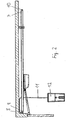
- FIG. 1 is a part of a garage, namely a lintel 1 and a ceiling 2, shown, to which a guide body, here a guide rail 3, preferably a cross-sectionally C-shaped rail, is attached.
- a guide body here a guide rail 3, preferably a cross-sectionally C-shaped rail
- On the guide rail 3 runs a carriage 4, which via a hinged rod 5 with the door leaf 6 of the garage is connected.
- the door leaf 6 facing away from the end 7 of the guide rail 3 is completed with a plug-in first insert body 8, while the door leaf 6 facing the end 9 of the guide rail 3 is completed with a plug-in second insert body 10.
- the first insert body 8 carries a power supply cable 11, which opens into a control housing 12 at the other end.
- the control housing 12 is plugged into a non-visible socket, which is located in the rear part of the garage.
- FIG. 1 similar FIG. 2 are the first insert body 8 and the second insert body 10 reversed after a turn by an angle of 180 °, so that now the end 9 with the first insert body 8 and the end 7 with the second insert body 10 is completed.
- the control housing 12 is plugged into a non-visible outlet, which is located in the front part of the garage.
- FIGS. 3 and 4 these two operating cases are the FIGS. 1 and 2 with respect to the guide rail 3, in particular profile rails, shown in more detail, wherein the FIG. 3 of the FIG. 1 and the FIG. 4 of the FIG. 2 listened.
- the first insert body 8 a Switzerlandstoffspann Anlagen 13 and the second insert body 10 a Switzerlandstoffspannvorraum 14, said Switzerlandstoffspannvortechnischen 13, 14 each comprise a hook 15 or other form-fitting, for example, the bayonet-like traction means locking part, which the tool-less fastening and Loosening of the traction means, without the use of an additional Switzerlandstoffheimsches permits and have a hook 15 adjustable in the rail longitudinal adjustment, such as in this FIGS.
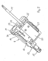
- the first insert body 8 is closer in FIG. 5 shown. It consists of a substantially cuboidal body of two adjoining parts 18, 19, which are made of plastic by injection molding in one piece.
- the first part 18 carries the Glasstoffspannvorraum 13 with the hook 15 and the adjuster 16, also serving to strain relief of the power connector cable 11 cover plate 20 and the side of a contact 21 which is provided for contacting the other core of the power connector cable 11 with the guide rail 3, so that the drive winding of the electric motor is connected to its other pole via this path with the connecting cable 11.
- the second part 19 has a slightly larger cross-section than the first part 18 and forms a circumferential stop 22 for the support of the inserted insert body 8 at the ends 7, 9 of the guide rail 3.
- the second part 19 has an opening on the front side 23 for access to Adjustment 16 and laterally two holes 24, 25, the attachment of the guide rail 3 on the lintel 1 (see FIG. 1 ) serve. As the FIGS. 3, 4 show, this attachment can be done by means of angles 26, 27.
- Another attachment point of the guide rail 3 is a bracket 28 which is fixed to the garage ceiling 2.
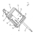
- FIG. 6 shows the turned first insert body 8, in which the stopper 22 is clearly visible.
- the second insert body 10 is preferably the same as the first insert body 8 is formed, but he lacks the connection cable 11. Also, the cover plate 20 and the contact 21 may be missing. The storage can therefore be limited to a single type of insert body, since the first insert body 8 and the second insert body 10 can be replaced.
Landscapes
- Power-Operated Mechanisms For Wings (AREA)
- Valve Device For Special Equipments (AREA)
- Seal Device For Vehicle (AREA)
- Vehicle Body Suspensions (AREA)
- Gates (AREA)
- Portable Nailing Machines And Staplers (AREA)
- Sink And Installation For Waste Water (AREA)
- Surgical Instruments (AREA)
- Types And Forms Of Lifts (AREA)
- Auxiliary Devices For And Details Of Packaging Control (AREA)
Abstract
Description
Die Erfindung betrifft eine Antriebsvorrichtung gemäß dem Oberbegriff des Anspruches 1.The invention relates to a drive device according to the preamble of claim 1.
Bei bekannten Vorrichtungen dieser Art können die Zuleitungsmittel als Schleppkabel oder aus einem Anschlusskabel und mit diesem verbundene Stromführungsschienen bestehen, die parallel zur Führungsschiene geführt werden und an denen der Strom für den Elektromotor abgenommen wird. Ferner ist auch bekannt, ein Zugmittel in der Führungsschiene längs anzuordnen und an deren Enden zu haltern sowie diese Kette als Stromzuführungsmittel für einen Elektromotor zu verwenden, der auf einem Schlitten an einer Führungsschiene entlang läuft. Das Zugmittel erhält dabei über eine an dem einen Ende der Führungsschiene für die Zugmittel angebrachte Spannvorrichtung den Antriebsstrom für den Elektromotor. Der Betrieb mit einem Schleppkabel ist für den Benutzer sehr störend, während in den Fällen der Stromschieneneinspeisung und der stromführenden Zugmittel die Stromeinspeisung nur von einem Ende der Führungsschiene möglich ist, in dessen Nähe die für die Stromeinspeisung nötige Netzsteckdose angeordnet ist. Soll der Antriebsstrom von dem anderen Ende der Führungsschiene eingespeist werden, weil die Steckdose in dessen Nähe liegt, so muss die Stromeinspeisung an der Führungsschiene aufwendig geändert werden, wenn nicht sogar zwei Ausführungen der Führungsschiene nötig sind und auf Lager gehalten werden müssen.In known devices of this type, the supply means may consist of a trailing cable or of a connection cable and power guide rails connected thereto, which are guided parallel to the guide rail and on which the current for the electric motor is removed. Further, it is also known to arrange a traction means in the guide rail longitudinally and to support at the ends thereof and to use this chain as a power supply means for an electric motor, which runs on a carriage along a guide rail. The traction means receives the drive current for the electric motor via a clamping device attached to one end of the guide rail for the traction means. The operation with a trailing cable is very disturbing for the user, while in the cases of the busbar supply and the current-carrying traction means, the power supply is only possible from one end of the guide rail, in the vicinity of which is necessary for the power supply power outlet is located. If the drive current to be fed from the other end of the guide rail, because the outlet is in the vicinity, the power supply to the guide rail must be changed consuming, if not two versions of the guide rail are required and must be kept in stock.
Eine Antriebsvorrichtung der eingangs genannten Art ist aus der
Am anderen Ende der Deckenschiene ist ein Deckel aufgeclipst. Durch den Deckel ist ein Gewindebolzen geführt, wobei dieser im Innern der Deckenschiene mit der Kette verbunden ist. Auf den Gewindebolzen ist eine Schraubendruckfeder geschoben, die sich einerseits am Deckel und andererseits über eine Öse an einer Mutter abstützt. Die Kette kann durch die Mutter gespannt werden. Nachteilig hierbei ist, dass zur Ankopplung des Gewindebolzens an die Kette Werkzeuge benötigt werden, wobei diese zudem in den Bereich der Deckenschiene eingeführt werden müssen, was umständlich und zeitaufwändig ist.At the other end of the ceiling rail, a lid is clipped. Through the lid a threaded bolt is guided, which is connected inside the ceiling rail with the chain. On the threaded bolt a helical compression spring is pushed, which is supported on the one hand on the lid and on the other hand via an eyelet to a nut. The chain can be tensioned by the nut. The disadvantage here is that for coupling the threaded bolt to the chain tools are needed, and these must also be introduced into the area of the ceiling rail, which is cumbersome and time-consuming.
Die
Der Erfindung liegt die Aufgabe zugrunde, eine Antriebsvorrichtung der eingangs genannten Art bereitzustellen, bei welcher die genannten Nachteile beseitigt sind.The invention has for its object to provide a drive device of the type mentioned, in which the disadvantages mentioned are eliminated.
Zur Lösung dieser Aufgabe sind die Merkmale des Anspruchs 1 vorgesehen. Vorteilhafte Ausführungsformen und zweckmäßige Weiterbildungen der Erfindung sind in den Unteransprüchen beschrieben. 'To solve this problem, the features of claim 1 are provided. Advantageous embodiments and expedient developments of the invention are described in the subclaims. '
Bei der erfindungsgemäßen Antriebsvorrichtung wird ein werkzeugloses Befestigen und Lösen des Zugmittels ohne Verwendung eines zusätzlichen Zugmittelschlosses ermöglicht.In the drive device according to the invention a tool-free fastening and releasing the traction means is made possible without the use of an additional Zugmittelschlosses.
Die Führungsschiene kann durch einfaches Umstecken des ersten Einsatzkörpers an den Ort der vorhandenen Steckdose angepasst werden.The guide rail can be adjusted by simply repositioning the first insert body to the location of the existing socket.
Es ist ein in die Führungsschienenenden steckbarer zweiter Einsatzkörper ohne Anschlusskabel vorgesehen, dessen sonstiger Aufbau dem des ersten Einsatzkörpers entspricht und der an demjenigen Führungschienenende angeordnet ist, das dem für den ersten Einsatzkörper vorgesehenen Führungsschienenende gegenüber liegt.It is provided in the guide rail ends second insert body without connecting cable, the other structure corresponds to that of the first insert body and which is arranged at that guide rail end, which is opposite to the intended for the first insert body guide rail end.
Eine vorteilhafte Ausbildung der Erfindung bezieht sich auf eine Antriebsvorrichtung, bei der die Stromzuführungsmittel die Führungsschiene selbst und ein Zugmittel umfassen, die an einem Führungsschienenende über die Zugmittelspannvorrichtung mit einem Anschlusskabel verbunden ist. Diese Ausbildung ist dadurch gekennzeichnet, dass der erste Einsatzkörper einen die Führungsschiene berührenden Kontaktkörper trägt. Die sonst übliche Klemmverbindung der einen Kabelanschlussader mit der Führungsschiene wird somit vermieden.An advantageous embodiment of the invention relates to a drive device in which the power supply means comprise the guide rail itself and a traction means which is connected at a guide rail end via the Zugmittelspannvorrichtung with a connecting cable. This embodiment is characterized in that the first insert body carries a contact body contacting the guide rail. The otherwise conventional clamping connection of a cable connection cable with the guide rail is thus avoided.
Gemäß einer weiteren Ausbildung der Erfindung weist der erste bzw. zweite Einsatzkörper einen die Zugmittelspannvorrichtung tragenden ersten Teil und einen einen umlaufenden Anschlag für den das Führungsschienenende bildenden zweiten Teil auf. Daher kann das Zugmittel in einfacher Weise gehaltert werden.According to a further embodiment of the invention, the first and second insert body on a Zugmittelspannvorrichtung supporting the first part and a circumferential stop for the guide rail end forming the second part. Therefore, the traction means can be easily supported.
Gemäß einer weiteren Ausbildung der Erfindung sind der erste Teil und der zweite Teil einstückig miteinander verbunden. Der Einsatzkörper kann daher als einfaches Kunststoff-Spritzteil hergestellt werden.According to a further embodiment of the invention, the first part and the second part are integrally connected to each other. The insert body can therefore be manufactured as a simple plastic injection molded part.
Gemäß einer weiteren Ausbildung der Erfindung weist der zweite Teil der Decken-, Wand- und Sturzbefestigung der Führungsschiene dienende Bohrungen auf. Der Einsatzkörper dient damit gleichzeitig als Stützpunkt für die Befestigung der Führungsschiene.According to a further embodiment of the invention, the second part of the ceiling, wall and lintel attachment of the guide rail serving bores on. The insert body thus serves at the same time as a base for the attachment of the guide rail.
Die Erfindung wird nun anhand eines Ausführungsbeispieles näher erläutert. Es zeigen:
- Figur 1:
- eine Seitenansicht einer Antriebsvorrichtung gemäß der Erfindung mit Anschluss von der dem Tor abgewandten Seite,
- Figur 2:
- eine Seitenansicht einer Antriebsvorrichtung gemäß der Erfindung mit Anschluss von der dem Tor zugewandten Seite,
- Figur 3:
- eine vergrößerte Ansicht der in der
Figur 1 gezeigten Führungsschiene von unten mit Einsatzkörpern, Anschlusskabel, Zugmittel und Schienenbefestigungsmitteln. - Figur 4:
- eine vergrößerte Ansicht der in der
Figur 2 - Figur 5:
- eine vergrößerte, perspektivische Ansicht eines ersten Einsatzkörpers bei Verwendung nach den
Figuren 1 ,3 und - Figur 6:
- eine vergrößerte, perspektivische Ansicht eines ersten Einsatzkörpers bei Verwendung nach den
Figuren 4 .
- FIG. 1:
- a side view of a drive device according to the invention with connection from the side facing away from the gate,
- FIG. 2:
- a side view of a drive device according to the invention with connection from the gate side facing,
- FIG. 3:
- an enlarged view of the in the
FIG. 1 shown guide rail from below with insert bodies, connecting cable, traction means and rail fasteners. - FIG. 4:
- an enlarged view of the in the
FIG. 2 shown guide rail from below with insert bodies, connecting cable, traction means and rail fasteners, - FIG. 5:
- an enlarged perspective view of a first insert body when used according to the
FIGS. 1 .3 and - FIG. 6:
- an enlarged perspective view of a first insert body when used according to the
Figures 2 .4 ,
In
In der der
In den
Der erste Einsatzkörper 8 ist näher in
Der erste Teil 18 trägt die Zugmittelspannvorrichtung 13 mit dem Haken 15 und der Einstellvorrichtung 16, eine auch zur Zugentlastung des Stromanschlusskabels 11 dienende Abdeckplatte 20 und seitlich einen Kontakt 21, der für die Kontaktierung der anderen Ader des Stromanschlusskabels 11 mit der Führungsschiene 3 vorgesehen ist, so dass die Antriebswicklung des Elektromotors mit ihrem anderen Pol über diesen Weg mit dem Anschlusskabel 11 verbunden ist.The
Der zweite Teil 19 hat einen etwas größeren Querschnitt als der erste Teil 18 und bildet einen umlaufenden Anschlag 22 für die Halterung des eingesteckten Einsatzkörpers 8 an den Enden 7, 9 der Führungsschiene 3. Der zweite Teil 19 weist stirnseitig eine Öffnung 23 für den Zugang zur Einstellvorrichtung 16 und seitlich zwei Bohrungen 24, 25 auf, die der Befestigung der Führungsschiene 3 am Sturz 1 (siehe
Der zweite Einsatzkörper 10 ist vorzugsweise genauso wie der erste Einsatzkörper 8 ausgebildet, doch fehlt ihm das Anschlusskabel 11. Auch die Abdeckplatte 20 und der Kontakt 21 können fehlen. Die Lagerhaltung kann daher auf einen einzigen Typ des Einsatzkörpers beschränkt werden, da der erste Einsatzkörper 8 und der zweite Einsatzkörper 10 ausgetauscht werden können.The
- (1)(1)
- Sturzfall
- (2)(2)
- Deckeblanket
- (3)(3)
- Führungsschieneguide rail
- (4)(4)
- Schlittencarriage
- (5)(5)
- Stangepole
- (6)(6)
- Torblattdoor leaf
- (7)(7)
- Ende der Führungsschiene (3)End of the guide rail (3)
- (8)(8th)
- Einsatzkörperinsert body
- (9)(9)
- Ende der Führungsschiene (3)End of the guide rail (3)
- (10)(10)
- Einsatzkörperinsert body
- (11)(11)
- StromanschlusskabelPower cable
- (12)(12)
- Steuergehäusecontrol housing
- (13)(13)
- Zugmittelspannvorrichtungtraction means tightening device
- (14)(14)
- Zugmittelspannvorrichtungtraction means tightening device
- (15)(15)
- Hakenhook
- (16)(16)
- Einstellvorrichtungadjustment
- (17)(17)
- Zugmitteltraction means
- (18)(18)
- Erster TeilFirst part
- (19)(19)
- Zweiter TeilSecond part
- (20)(20)
- Abdeckplattecover
- (21)(21)
- KontaktContact
- (22)(22)
- Anschlagattack
- (23)(23)
- Öffnungopening
- (24)(24)
- Bohrungdrilling
- (25)(25)
- Bohrungdrilling
- (26)(26)
- Winkelangle
- (27)(27)
- Winkelangle
- (28)(28)
- Bügelhanger
Claims (10)
- Drive device for a door, with a guide device extending in the direction of movement of the door, with a slide, which is movable at the guide device and comprises an electric motor, for actuating of a door leaf, and with current feed means for connection of the electric motor with a current source, wherein the current feed means comprise a traction means (17) disposed in engagement with the electric motor, characterised in that the current feed means additionally comprise a first insert body (8) and a second insert body (10), which after turning through an angle 180° are selectably insertable into one of the longitudinal ends of the guide device, wherein the first and second insert bodies (8, 10) each comprise a traction means tightening device (13, 14) with a part, which locks the traction means and which is constructed in the form of a hook or is of bayonet-like construction, and wherein the traction means (17) is connected by way of the traction means clamping device of the first insert body (8) with a connecting cable (11).
- Drive device according to claim 1, characterised in that the traction means (17) is tightened between the traction means tightening devices (13, 14) of the insert bodies (8, 10) at the longitudinal ends of the guide device.
- Drive device according to one of claims 1 and 2, characterised in that the traction means (17) is formed by a chain.
- Drive device according to any one of claim 1 to 3, characterised in that the guide device is formed by a guide rail (3) which is a component of the current feed means.
- Drive device according to claim 4, characterised in that the or each insert body (8, 10) comprises a first part (18) supporting the traction means tightening device (13, 14) and a second part (19) forming an abutment (22) for mounting at one end of the guide rail (3), wherein an opening (23) as access for a setting device (16) of the traction means tightening device (14) is provided in the part (19).
- Drive device according to claim 5, characterised in that the mechanically positively lockable part of the traction means tightening device (13, 14) is adjustable in the longitudinal direction of the guide rail (3) by means of the setting device (16).
- Drive device according to any one of claims 8 to 10, characterised in that the first insert body (8) as a component of the current feed means is provided with a connecting cable (11) and carries the contact body (21) contacting the guide rail (3).
- Drive device according to claim 7, characterised in that the traction means tightening device (13, 14) and the tightening means (17) are connected with a first wire of the connecting cable (11).
- Drive device according to one of claims 7 and 8, characterised in that a cover plate (20) is provided as tension relief of the connecting cable (11).
- Drive device according to any one of claims 7 to 9, characterised in that the contact body (21) is connected with a second wire of the connecting cable (11).
Priority Applications (1)
| Application Number | Priority Date | Filing Date | Title |
|---|---|---|---|
| SI200331906T SI1574656T1 (en) | 2002-06-17 | 2003-06-05 | Driving device for a gate |
Applications Claiming Priority (3)
| Application Number | Priority Date | Filing Date | Title |
|---|---|---|---|
| DE10227110A DE10227110B4 (en) | 2002-06-17 | 2002-06-17 | driving device |
| DE10227110 | 2002-06-17 | ||
| EP03740188A EP1514001B1 (en) | 2002-06-17 | 2003-06-05 | Drive device |
Related Parent Applications (2)
| Application Number | Title | Priority Date | Filing Date |
|---|---|---|---|
| EP03740188A Division EP1514001B1 (en) | 2002-06-17 | 2003-06-05 | Drive device |
| EP03740188.2 Division | 2003-06-05 |
Publications (3)
| Publication Number | Publication Date |
|---|---|
| EP1574656A2 EP1574656A2 (en) | 2005-09-14 |
| EP1574656A3 EP1574656A3 (en) | 2005-11-23 |
| EP1574656B1 true EP1574656B1 (en) | 2010-09-01 |
Family
ID=29719195
Family Applications (2)
| Application Number | Title | Priority Date | Filing Date |
|---|---|---|---|
| EP05011657A Revoked EP1574656B1 (en) | 2002-06-17 | 2003-06-05 | Driving device for a gate |
| EP03740188A Expired - Lifetime EP1514001B1 (en) | 2002-06-17 | 2003-06-05 | Drive device |
Family Applications After (1)
| Application Number | Title | Priority Date | Filing Date |
|---|---|---|---|
| EP03740188A Expired - Lifetime EP1514001B1 (en) | 2002-06-17 | 2003-06-05 | Drive device |
Country Status (17)
| Country | Link |
|---|---|
| US (1) | US7748167B2 (en) |
| EP (2) | EP1574656B1 (en) |
| CN (2) | CN100351489C (en) |
| AT (2) | ATE467029T1 (en) |
| AU (1) | AU2003275874B2 (en) |
| CA (1) | CA2488395C (en) |
| DE (3) | DE10227110B4 (en) |
| DK (2) | DK1574656T3 (en) |
| ES (2) | ES2343791T3 (en) |
| HU (1) | HU227998B1 (en) |
| MX (1) | MXPA04012248A (en) |
| PL (1) | PL207677B1 (en) |
| PT (2) | PT1574656E (en) |
| RU (1) | RU2296843C2 (en) |
| SI (2) | SI1514001T1 (en) |
| WO (1) | WO2003106797A1 (en) |
| ZA (1) | ZA200410124B (en) |
Families Citing this family (13)
| Publication number | Priority date | Publication date | Assignee | Title |
|---|---|---|---|---|
| US8062891B2 (en) * | 2003-10-24 | 2011-11-22 | Gencia Corporation | Nonviral vectors for delivering polynucleotides to plants |
| DE102006001892A1 (en) | 2006-01-14 | 2007-07-19 | Sommer Antriebs- Und Funktechnik Gmbh | Electrically powered drive for a garage door is contained in a sliding carriage mounted on a ceiling fixed rail |
| DE102006004790B4 (en) * | 2006-02-02 | 2015-10-01 | Roma Kg | Overhead door |
| DE102007002034B4 (en) | 2007-01-13 | 2012-09-06 | Sommer Antriebs- Und Funktechnik Gmbh | Drive device for a gate |
| DE102007010209B4 (en) * | 2007-03-02 | 2010-07-08 | Sommer Antriebs- Und Funktechnik Gmbh | driving device |
| DE102008004050B4 (en) * | 2008-01-11 | 2011-04-07 | Sommer Antriebs- Und Funktechnik Gmbh | Drive system for a gate |
| DE102008046538B4 (en) * | 2008-09-10 | 2014-08-07 | Sommer Antriebs- Und Funktechnik Gmbh | Drive system for a gate |
| DE202009000929U1 (en) * | 2009-01-24 | 2009-03-26 | Sommer Antriebs- Und Funktechnik Gmbh | Drive system for a gate |
| DE102009026996B4 (en) * | 2009-06-17 | 2013-03-07 | Geze Gmbh | Automatic door system |
| ITTV20120107A1 (en) | 2012-06-04 | 2013-12-05 | Nice Spa | ELECTROMECHANICAL OPERATION FOR GARAGE DOOR |
| DE202015103728U1 (en) | 2015-07-16 | 2016-10-18 | Sommer Antriebs- Und Funktechnik Gmbh | Drive system for a gate |
| DE202016102662U1 (en) * | 2016-05-19 | 2017-08-22 | Sommer Antriebs- Und Funktechnik Gmbh | gate |
| CN119582518A (en) * | 2025-02-08 | 2025-03-07 | 江苏科脉仪器仪表制造有限公司 | A motor-driven two-core wire control device |
Family Cites Families (10)
| Publication number | Priority date | Publication date | Assignee | Title |
|---|---|---|---|---|
| US1981026A (en) * | 1928-03-16 | 1934-11-20 | Door Control Company | Electric door control |
| US3331428A (en) * | 1964-06-11 | 1967-07-18 | Kirsch Co | Structural device |
| JPS57100277A (en) * | 1980-12-12 | 1982-06-22 | Hitachi Ltd | Apparatus for controlling door opening and closing |
| DE8806956U1 (en) | 1988-05-27 | 1989-09-28 | Robert Bosch Gmbh, 7000 Stuttgart | Gate drive |
| DE9406829U1 (en) * | 1994-04-23 | 1995-08-31 | Robert Bosch Gmbh, 70469 Stuttgart | Electromotive door drive, in particular for a garage door |
| HUP0003524A3 (en) * | 1996-09-18 | 2001-03-28 | Hoermann Kg Antriebstechnik | End stop on c-shaped guide profile for motor-driven objects |
| DE19808696A1 (en) * | 1998-02-06 | 1999-08-12 | Sommer Gmbh | Electromechanical garage door operator |
| DE19804801C1 (en) * | 1998-02-09 | 1999-07-08 | Dorma Gmbh & Co Kg | End cap fixing device |
| JP2929009B1 (en) * | 1998-07-29 | 1999-08-03 | 株式会社ソリック | Hanger roller drop-off prevention device for automatic door device door |
| RU18416U1 (en) * | 2001-02-19 | 2001-06-20 | Подымов Олег Владимирович | GARAGE DOORS |
-
2002
- 2002-06-17 DE DE10227110A patent/DE10227110B4/en not_active Expired - Fee Related
- 2002-06-17 DE DE10262147A patent/DE10262147B4/en not_active Revoked
-
2003
- 2003-06-05 PL PL372839A patent/PL207677B1/en unknown
- 2003-06-05 PT PT05011657T patent/PT1574656E/en unknown
- 2003-06-05 ES ES03740188T patent/ES2343791T3/en not_active Expired - Lifetime
- 2003-06-05 DE DE50313050T patent/DE50313050D1/en not_active Expired - Lifetime
- 2003-06-05 AU AU2003275874A patent/AU2003275874B2/en not_active Ceased
- 2003-06-05 US US10/518,360 patent/US7748167B2/en not_active Expired - Fee Related
- 2003-06-05 CN CNB038140497A patent/CN100351489C/en not_active Expired - Fee Related
- 2003-06-05 SI SI200331840T patent/SI1514001T1/en unknown
- 2003-06-05 DK DK05011657.3T patent/DK1574656T3/en active
- 2003-06-05 DK DK03740188.2T patent/DK1514001T3/en active
- 2003-06-05 SI SI200331906T patent/SI1574656T1/en unknown
- 2003-06-05 AT AT03740188T patent/ATE467029T1/en active
- 2003-06-05 ES ES05011657T patent/ES2351342T3/en not_active Expired - Lifetime
- 2003-06-05 CN CN2007100083803A patent/CN1991119B/en not_active Expired - Fee Related
- 2003-06-05 WO PCT/EP2003/005901 patent/WO2003106797A1/en not_active Ceased
- 2003-06-05 RU RU2004136290/12A patent/RU2296843C2/en not_active IP Right Cessation
- 2003-06-05 EP EP05011657A patent/EP1574656B1/en not_active Revoked
- 2003-06-05 EP EP03740188A patent/EP1514001B1/en not_active Expired - Lifetime
- 2003-06-05 HU HU0500261A patent/HU227998B1/en not_active IP Right Cessation
- 2003-06-05 PT PT03740188T patent/PT1514001E/en unknown
- 2003-06-05 MX MXPA04012248A patent/MXPA04012248A/en active IP Right Grant
- 2003-06-05 CA CA2488395A patent/CA2488395C/en not_active Expired - Fee Related
- 2003-06-05 AT AT05011657T patent/ATE479816T1/en active
-
2004
- 2004-12-15 ZA ZA200410124A patent/ZA200410124B/en unknown
Also Published As
Similar Documents
| Publication | Publication Date | Title |
|---|---|---|
| DE102007013446B4 (en) | Electric actuator | |
| EP1514001B1 (en) | Drive device | |
| EP2382365B1 (en) | Drive system for a door | |
| EP1725788B1 (en) | Sliding door system | |
| EP2927409B1 (en) | Sealing arrangement for a push door | |
| DE102025103059A1 (en) | Tensioning device for a window regulator | |
| EP2634344B1 (en) | Drive for a wing of a window or the like and method for fitting an end cap of the drive | |
| EP2227615B1 (en) | Drive system for a gate | |
| DE102011056416B4 (en) | Arrangement of a drive unit of an opening or locking device | |
| EP2270302B1 (en) | Power transmission device for a door assembly | |
| EP0943824A1 (en) | Fastener | |
| EP2320022B1 (en) | Hinge for an insect and/or pollen protection screen | |
| DE69810380T2 (en) | Door closer, thus equipped door and rail vehicle with at least one such device and / or door | |
| DE102018129581B4 (en) | Auxiliary drive for a motor-driven door leaf, as well as a door with an auxiliary drive | |
| EP1860264B1 (en) | Refrigerator and/or freezer | |
| DE102005051997C5 (en) | gate | |
| DE102004054028A1 (en) | Door e.g. glass door, positioning device, has retaining units arranged together in given position of door so that magnets are arranged at distance to each other and work together, where distance between two magnets is adjustable | |
| DE10162036C1 (en) | Drive for raising and lowering a window has cable drive attached to mounting via hooks engaging in recesses in mounting | |
| DE202007002433U1 (en) | Holder for hinge band for doors and windows has assembly section on one side for fitting band and a guide socket on other side for holding service leads | |
| DE102017207981B4 (en) | Cable bridge device and cable bridge arrangement | |
| EP4263994A1 (en) | Drive of a sliding door of a motor vehicle | |
| DE102011054113B3 (en) | Window lifter installed in door e.g. frameless door of motor vehicle, has additional guide unit that is provided to guide driver only along portion of displacement path | |
| DE10257214B4 (en) | Housing for electrical installation equipment | |
| EP1557518A1 (en) | Garage door drive | |
| DE202005014420U1 (en) | Window lift of a motor vehicle |
Legal Events
| Date | Code | Title | Description |
|---|---|---|---|
| PUAI | Public reference made under article 153(3) epc to a published international application that has entered the european phase |
Free format text: ORIGINAL CODE: 0009012 |
|
| AC | Divisional application: reference to earlier application |
Ref document number: 1514001 Country of ref document: EP Kind code of ref document: P |
|
| AK | Designated contracting states |
Kind code of ref document: A2 Designated state(s): AT BE BG CH CY CZ DE DK EE ES FI FR GB GR HU IE IT LI LU MC NL PT RO SE SI SK TR |
|
| AX | Request for extension of the european patent |
Extension state: AL LV MK |
|
| PUAL | Search report despatched |
Free format text: ORIGINAL CODE: 0009013 |
|
| AK | Designated contracting states |
Kind code of ref document: A3 Designated state(s): AT BE BG CH CY CZ DE DK EE ES FI FR GB GR HU IE IT LI LU MC NL PT RO SE SI SK TR |
|
| AX | Request for extension of the european patent |
Extension state: AL LV MK |
|
| 17P | Request for examination filed |
Effective date: 20051208 |
|
| AKX | Designation fees paid |
Designated state(s): AT BE BG CH CY CZ DE DK EE ES FI FR GB GR HU IE IT LI LU MC NL PT RO SE SI SK TR |
|
| GRAP | Despatch of communication of intention to grant a patent |
Free format text: ORIGINAL CODE: EPIDOSNIGR1 |
|
| GRAS | Grant fee paid |
Free format text: ORIGINAL CODE: EPIDOSNIGR3 |
|
| GRAA | (expected) grant |
Free format text: ORIGINAL CODE: 0009210 |
|
| AC | Divisional application: reference to earlier application |
Ref document number: 1514001 Country of ref document: EP Kind code of ref document: P |
|
| AK | Designated contracting states |
Kind code of ref document: B1 Designated state(s): AT BE BG CH CY CZ DE DK EE ES FI FR GB GR HU IE IT LI LU MC NL PT RO SE SI SK TR |
|
| REG | Reference to a national code |
Ref country code: GB Ref legal event code: FG4D Free format text: NOT ENGLISH |
|
| REG | Reference to a national code |
Ref country code: CH Ref legal event code: NV Representative=s name: ROTTMANN, ZIMMERMANN + PARTNER AG Ref country code: CH Ref legal event code: EP |
|
| REG | Reference to a national code |
Ref country code: PT Ref legal event code: SC4A Free format text: AVAILABILITY OF NATIONAL TRANSLATION Effective date: 20100915 |
|
| REG | Reference to a national code |
Ref country code: IE Ref legal event code: FG4D Free format text: LANGUAGE OF EP DOCUMENT: GERMAN |
|
| REF | Corresponds to: |
Ref document number: 50313050 Country of ref document: DE Date of ref document: 20101014 Kind code of ref document: P |
|
| REG | Reference to a national code |
Ref country code: DK Ref legal event code: T3 |
|
| REG | Reference to a national code |
Ref country code: SE Ref legal event code: TRGR |
|
| REG | Reference to a national code |
Ref country code: NL Ref legal event code: T3 |
|
| PG25 | Lapsed in a contracting state [announced via postgrant information from national office to epo] |
Ref country code: FI Free format text: LAPSE BECAUSE OF FAILURE TO SUBMIT A TRANSLATION OF THE DESCRIPTION OR TO PAY THE FEE WITHIN THE PRESCRIBED TIME-LIMIT Effective date: 20100901 |
|
| REG | Reference to a national code |
Ref country code: ES Ref legal event code: FG2A Effective date: 20110124 |
|
| PG25 | Lapsed in a contracting state [announced via postgrant information from national office to epo] |
Ref country code: CY Free format text: LAPSE BECAUSE OF FAILURE TO SUBMIT A TRANSLATION OF THE DESCRIPTION OR TO PAY THE FEE WITHIN THE PRESCRIBED TIME-LIMIT Effective date: 20100901 |
|
| REG | Reference to a national code |
Ref country code: IE Ref legal event code: FD4D |
|
| PG25 | Lapsed in a contracting state [announced via postgrant information from national office to epo] |
Ref country code: GR Free format text: LAPSE BECAUSE OF FAILURE TO SUBMIT A TRANSLATION OF THE DESCRIPTION OR TO PAY THE FEE WITHIN THE PRESCRIBED TIME-LIMIT Effective date: 20101202 |
|
| PG25 | Lapsed in a contracting state [announced via postgrant information from national office to epo] |
Ref country code: MC Free format text: LAPSE BECAUSE OF NON-PAYMENT OF DUE FEES Effective date: 20100930 Ref country code: IE Free format text: LAPSE BECAUSE OF FAILURE TO SUBMIT A TRANSLATION OF THE DESCRIPTION OR TO PAY THE FEE WITHIN THE PRESCRIBED TIME-LIMIT Effective date: 20100901 |
|
| PG25 | Lapsed in a contracting state [announced via postgrant information from national office to epo] |
Ref country code: RO Free format text: LAPSE BECAUSE OF FAILURE TO SUBMIT A TRANSLATION OF THE DESCRIPTION OR TO PAY THE FEE WITHIN THE PRESCRIBED TIME-LIMIT Effective date: 20100901 Ref country code: SK Free format text: LAPSE BECAUSE OF FAILURE TO SUBMIT A TRANSLATION OF THE DESCRIPTION OR TO PAY THE FEE WITHIN THE PRESCRIBED TIME-LIMIT Effective date: 20100901 Ref country code: EE Free format text: LAPSE BECAUSE OF FAILURE TO SUBMIT A TRANSLATION OF THE DESCRIPTION OR TO PAY THE FEE WITHIN THE PRESCRIBED TIME-LIMIT Effective date: 20100901 |
|
| PLBI | Opposition filed |
Free format text: ORIGINAL CODE: 0009260 |
|
| PLAX | Notice of opposition and request to file observation + time limit sent |
Free format text: ORIGINAL CODE: EPIDOSNOBS2 |
|
| 26 | Opposition filed |
Opponent name: AVANTI-ANTRIEBE GMBH & CO. KG Effective date: 20110530 |
|
| REG | Reference to a national code |
Ref country code: DE Ref legal event code: R026 Ref document number: 50313050 Country of ref document: DE Effective date: 20110530 |
|
| REG | Reference to a national code |
Ref country code: CH Ref legal event code: PFA Owner name: SOMMER ANTRIEBS- UND FUNKTECHNIK GMBH Free format text: SOMMER ANTRIEBS- UND FUNKTECHNIK GMBH#HANS-BOECKLER-STRASSE 21-27#73230 KIRCHHEIM/TECK (DE) -TRANSFER TO- SOMMER ANTRIEBS- UND FUNKTECHNIK GMBH#HANS-BOECKLER-STRASSE 21-27#73230 KIRCHHEIM/TECK (DE) |
|
| PLBB | Reply of patent proprietor to notice(s) of opposition received |
Free format text: ORIGINAL CODE: EPIDOSNOBS3 |
|
| PLCK | Communication despatched that opposition was rejected |
Free format text: ORIGINAL CODE: EPIDOSNREJ1 |
|
| APAH | Appeal reference modified |
Free format text: ORIGINAL CODE: EPIDOSCREFNO |
|
| APBM | Appeal reference recorded |
Free format text: ORIGINAL CODE: EPIDOSNREFNO |
|
| APBP | Date of receipt of notice of appeal recorded |
Free format text: ORIGINAL CODE: EPIDOSNNOA2O |
|
| APBQ | Date of receipt of statement of grounds of appeal recorded |
Free format text: ORIGINAL CODE: EPIDOSNNOA3O |
|
| PG25 | Lapsed in a contracting state [announced via postgrant information from national office to epo] |
Ref country code: LU Free format text: LAPSE BECAUSE OF NON-PAYMENT OF DUE FEES Effective date: 20110605 |
|
| PG25 | Lapsed in a contracting state [announced via postgrant information from national office to epo] |
Ref country code: BG Free format text: LAPSE BECAUSE OF FAILURE TO SUBMIT A TRANSLATION OF THE DESCRIPTION OR TO PAY THE FEE WITHIN THE PRESCRIBED TIME-LIMIT Effective date: 20101201 Ref country code: TR Free format text: LAPSE BECAUSE OF FAILURE TO SUBMIT A TRANSLATION OF THE DESCRIPTION OR TO PAY THE FEE WITHIN THE PRESCRIBED TIME-LIMIT Effective date: 20100901 |
|
| PG25 | Lapsed in a contracting state [announced via postgrant information from national office to epo] |
Ref country code: HU Free format text: LAPSE BECAUSE OF FAILURE TO SUBMIT A TRANSLATION OF THE DESCRIPTION OR TO PAY THE FEE WITHIN THE PRESCRIBED TIME-LIMIT Effective date: 20100901 |
|
| PGFP | Annual fee paid to national office [announced via postgrant information from national office to epo] |
Ref country code: CZ Payment date: 20140723 Year of fee payment: 12 |
|
| PGFP | Annual fee paid to national office [announced via postgrant information from national office to epo] |
Ref country code: SI Payment date: 20140711 Year of fee payment: 12 |
|
| PGFP | Annual fee paid to national office [announced via postgrant information from national office to epo] |
Ref country code: PT Payment date: 20140605 Year of fee payment: 12 |
|
| REG | Reference to a national code |
Ref country code: FR Ref legal event code: PLFP Year of fee payment: 13 |
|
| PGFP | Annual fee paid to national office [announced via postgrant information from national office to epo] |
Ref country code: CH Payment date: 20150618 Year of fee payment: 13 Ref country code: SE Payment date: 20150618 Year of fee payment: 13 Ref country code: ES Payment date: 20150626 Year of fee payment: 13 Ref country code: GB Payment date: 20150618 Year of fee payment: 13 Ref country code: DK Payment date: 20150618 Year of fee payment: 13 |
|
| APBU | Appeal procedure closed |
Free format text: ORIGINAL CODE: EPIDOSNNOA9O |
|
| PGFP | Annual fee paid to national office [announced via postgrant information from national office to epo] |
Ref country code: NL Payment date: 20150618 Year of fee payment: 13 Ref country code: FR Payment date: 20150619 Year of fee payment: 13 Ref country code: AT Payment date: 20150619 Year of fee payment: 13 Ref country code: BE Payment date: 20150618 Year of fee payment: 13 |
|
| REG | Reference to a national code |
Ref country code: PT Ref legal event code: MM4A Free format text: LAPSE DUE TO NON-PAYMENT OF FEES Effective date: 20151207 |
|
| PG25 | Lapsed in a contracting state [announced via postgrant information from national office to epo] |
Ref country code: CZ Free format text: LAPSE BECAUSE OF NON-PAYMENT OF DUE FEES Effective date: 20150605 Ref country code: PT Free format text: LAPSE BECAUSE OF NON-PAYMENT OF DUE FEES Effective date: 20151207 |
|
| REG | Reference to a national code |
Ref country code: SI Ref legal event code: KO00 Effective date: 20160222 |
|
| PG25 | Lapsed in a contracting state [announced via postgrant information from national office to epo] |
Ref country code: SI Free format text: LAPSE BECAUSE OF NON-PAYMENT OF DUE FEES Effective date: 20150606 |
|
| REG | Reference to a national code |
Ref country code: CH Ref legal event code: PCAR Free format text: NEW ADDRESS: GARTENSTRASSE 28 A, 5400 BADEN (CH) |
|
| PG25 | Lapsed in a contracting state [announced via postgrant information from national office to epo] |
Ref country code: BE Free format text: LAPSE BECAUSE OF NON-PAYMENT OF DUE FEES Effective date: 20160630 |
|
| REG | Reference to a national code |
Ref country code: DK Ref legal event code: EBP Effective date: 20160630 |
|
| REG | Reference to a national code |
Ref country code: SE Ref legal event code: EUG Ref country code: CH Ref legal event code: PL |
|
| REG | Reference to a national code |
Ref country code: NL Ref legal event code: MM Effective date: 20160701 |
|
| REG | Reference to a national code |
Ref country code: AT Ref legal event code: MM01 Ref document number: 479816 Country of ref document: AT Kind code of ref document: T Effective date: 20160605 |
|
| PG25 | Lapsed in a contracting state [announced via postgrant information from national office to epo] |
Ref country code: SE Free format text: LAPSE BECAUSE OF NON-PAYMENT OF DUE FEES Effective date: 20160606 |
|
| GBPC | Gb: european patent ceased through non-payment of renewal fee |
Effective date: 20160605 |
|
| REG | Reference to a national code |
Ref country code: FR Ref legal event code: ST Effective date: 20170228 |
|
| PG25 | Lapsed in a contracting state [announced via postgrant information from national office to epo] |
Ref country code: LI Free format text: LAPSE BECAUSE OF NON-PAYMENT OF DUE FEES Effective date: 20160630 Ref country code: CH Free format text: LAPSE BECAUSE OF NON-PAYMENT OF DUE FEES Effective date: 20160630 Ref country code: FR Free format text: LAPSE BECAUSE OF NON-PAYMENT OF DUE FEES Effective date: 20160630 |
|
| PG25 | Lapsed in a contracting state [announced via postgrant information from national office to epo] |
Ref country code: GB Free format text: LAPSE BECAUSE OF NON-PAYMENT OF DUE FEES Effective date: 20160605 Ref country code: AT Free format text: LAPSE BECAUSE OF NON-PAYMENT OF DUE FEES Effective date: 20160605 Ref country code: NL Free format text: LAPSE BECAUSE OF NON-PAYMENT OF DUE FEES Effective date: 20160701 |
|
| PG25 | Lapsed in a contracting state [announced via postgrant information from national office to epo] |
Ref country code: DK Free format text: LAPSE BECAUSE OF NON-PAYMENT OF DUE FEES Effective date: 20160630 |
|
| PG25 | Lapsed in a contracting state [announced via postgrant information from national office to epo] |
Ref country code: ES Free format text: LAPSE BECAUSE OF NON-PAYMENT OF DUE FEES Effective date: 20160606 |
|
| REG | Reference to a national code |
Ref country code: ES Ref legal event code: FD2A Effective date: 20180626 |
|
| PGFP | Annual fee paid to national office [announced via postgrant information from national office to epo] |
Ref country code: DE Payment date: 20180530 Year of fee payment: 16 |
|
| PGFP | Annual fee paid to national office [announced via postgrant information from national office to epo] |
Ref country code: IT Payment date: 20180627 Year of fee payment: 16 |
|
| REG | Reference to a national code |
Ref country code: DE Ref legal event code: R119 Ref document number: 50313050 Country of ref document: DE |
|
| PG25 | Lapsed in a contracting state [announced via postgrant information from national office to epo] |
Ref country code: DE Free format text: LAPSE BECAUSE OF NON-PAYMENT OF DUE FEES Effective date: 20200101 Ref country code: IT Free format text: LAPSE BECAUSE OF NON-PAYMENT OF DUE FEES Effective date: 20190605 |
|
| RDAF | Communication despatched that patent is revoked |
Free format text: ORIGINAL CODE: EPIDOSNREV1 |
|
| STAA | Information on the status of an ep patent application or granted ep patent |
Free format text: STATUS: THE PATENT HAS BEEN GRANTED |
|
| REG | Reference to a national code |
Ref country code: DE Ref legal event code: R064 Ref document number: 50313050 Country of ref document: DE Ref country code: DE Ref legal event code: R103 Ref document number: 50313050 Country of ref document: DE |
|
| RDAG | Patent revoked |
Free format text: ORIGINAL CODE: 0009271 |
|
| STAA | Information on the status of an ep patent application or granted ep patent |
Free format text: STATUS: PATENT REVOKED |
|
| REG | Reference to a national code |
Ref country code: FI Ref legal event code: MGE |
|
| 27W | Patent revoked |
Effective date: 20200524 |
|
| REG | Reference to a national code |
Ref country code: AT Ref legal event code: MA03 Ref document number: 479816 Country of ref document: AT Kind code of ref document: T Effective date: 20200524 |