EP1574468A1 - Einrichtung zur Befestigung einer Kabinenkamera - Google Patents
Einrichtung zur Befestigung einer Kabinenkamera Download PDFInfo
- Publication number
- EP1574468A1 EP1574468A1 EP05002457A EP05002457A EP1574468A1 EP 1574468 A1 EP1574468 A1 EP 1574468A1 EP 05002457 A EP05002457 A EP 05002457A EP 05002457 A EP05002457 A EP 05002457A EP 1574468 A1 EP1574468 A1 EP 1574468A1
- Authority
- EP
- European Patent Office
- Prior art keywords
- camera
- cabin
- bracket
- car
- ceiling
- Prior art date
- Legal status (The legal status is an assumption and is not a legal conclusion. Google has not performed a legal analysis and makes no representation as to the accuracy of the status listed.)
- Granted
Links
- 238000000034 method Methods 0.000 claims abstract 2
- 238000007689 inspection Methods 0.000 claims 1
- 238000012544 monitoring process Methods 0.000 abstract 1
- 239000002313 adhesive film Substances 0.000 description 2
- 230000001419 dependent effect Effects 0.000 description 1
- 238000011161 development Methods 0.000 description 1
- 230000018109 developmental process Effects 0.000 description 1
- 238000012806 monitoring device Methods 0.000 description 1
Images
Classifications
-
- B—PERFORMING OPERATIONS; TRANSPORTING
- B66—HOISTING; LIFTING; HAULING
- B66B—ELEVATORS; ESCALATORS OR MOVING WALKWAYS
- B66B19/00—Mining-hoist operation
- B66B19/007—Mining-hoist operation method for modernisation of elevators
-
- B—PERFORMING OPERATIONS; TRANSPORTING
- B66—HOISTING; LIFTING; HAULING
- B66B—ELEVATORS; ESCALATORS OR MOVING WALKWAYS
- B66B5/00—Applications of checking, fault-correcting, or safety devices in elevators
- B66B5/0006—Monitoring devices or performance analysers
- B66B5/0012—Devices monitoring the users of the elevator system
Definitions
- the invention relates to a device for attachment a cabin camera by means of the inside of a Elevator car is monitored, with the cabin camera on one of the cabin walls or arranged on the cabin ceiling is.
- a disadvantage of the known device is that Two cameras are necessary to monitor the cabin interior are, which is expensive and also an expensive controller necessary.
- the invention aims to remedy this situation.
- the invention as characterized in claim 1 solves the task to avoid the disadvantages of the known device and an elevator car with a simple Propose monitoring device.
- the advantages achieved by the invention are in essential to see that outside the Elevator car arranged security camera easy in all layers can be aligned. With only one Security camera and one always same Fastening device may elevator cars with different floor plans and different sizes be monitored.
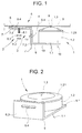
- Fig. 1 shows a car camera 1 bearing Fastening device 2, on the outside of the cabin 3
- the fastening device 2 can also on be arranged on the outside of the cabin ceiling.
- the Fastening device 2 consists of a first bracket 6, where the camera 1 is arranged.
- the first bracket 6 is carried by a second bracket 7, which at one Base plate 8 is arranged.
- the cabin wall 4 is with provided at least one opening 9, through which the camera. 1 Insight into the elevator car 5 can take.
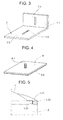
- Fig. 2 shows the first bracket 6 on which the camera 1 am long leg 6.1 of the bracket by means of screws 10th is attached.
- the long leg 6.1 has an opening 6.2, through which a cable 1.1 of the camera 1 is guided.
- a short leg of the bracket 6 is denoted by 6.3 and has a slot 6.4, which means the attachment at least one screw 11 on the second bracket 7 is used.
- the Camera 1 is arranged in a housing 1.2, wherein a Housing ring 1.21 holds the camera 1.
- With 1.3 is the Lens of the camera 1, wherein the lens 1.3 means the fastening device 2 on the opening. 9 is einjustierbar.
- Fig. 3 shows the second leg 7 consisting of a short leg 7.1 with slot 7.2 and a long Leg 7.3 with slot 7.4.
- the short leg is 7.1 by means of the screw 11 with the short leg 6.3 of first bracket 6 connected.
- the base plate 8 shows the base plate 8 with a threaded bolt 8.1, which fits into the slot 7.4 of the second bracket 7, wherein a nut 8.2 and a washer 8.3 a detachable Connection between the base plate 8 and the second bracket 7 produces.
- the base plate 8 is a two-sided Adhesive film 8.4 provided, the base plate 8 with the Cabin wall 4 connects. Instead of the adhesive film 8.4 can also a screw or a rivet connection be provided.
- Fig. 5 shows a section through the housing 1.2 and the Housing ring 1.21, which holds the camera 1 in the housing 1.2, wherein the housing ring 1.21 on the housing 1.2 can be screwed on.
- An internal thread 1.22 of the housing ring 1.21 fits on an external thread 1.23 of the housing 1.2.
- first bracket 6 may be arranged a ball joint which carries the camera 1.
Landscapes
- Fittings On The Vehicle Exterior For Carrying Loads, And Devices For Holding Or Mounting Articles (AREA)
- Closed-Circuit Television Systems (AREA)
- Cage And Drive Apparatuses For Elevators (AREA)
- Traffic Control Systems (AREA)
Abstract
Description
eine Befestigungseinrichtung für eine Kamera,
einen ersten Befestigungsbügel mit der Kamera,
einen zweiten Befestigungsbügel,
eine Grundplatte und
Einzelheiten eines Gehäuses für die Kamera.
Claims (7)
- Einrichtung zur Befestigung einer Kabinenkamera (1) mittels der das Innere einer Aufzugskabine (5) überwachbar ist, wobei die Kabinenkamera (1) an einer der Kabinenwände (4) oder an der Kabinendecke angeordnet ist,
dadurch gekennzeichnet, dass die Kabinenkamera (1) an einer Befestigungseinrichtung (2) angeordnet ist, mittels der eine Linse (1.3) der Kabinenkamera (1) auf eine Öffnung (9) der Kabinenwand (4) oder der Kabinendecke justierbar ist, durch welche Öffnung (9) die Kabinenkamera (1) Einsicht in die Aufzugskabine (5) nehmen kann. - Einrichtung nach Anspruch 1,
dadurch gekennzeichnet, dass die Befestigungseinrichtung (2) mehrere Tragelemente (6,7,8) aufweist, die gegeneinander verschiebbar sind. - Einrichtung nach Anspruch 2,
dadurch gekennzeichnet, dass ein erster Bügel (6) vorgesehen ist, an dem die Kabinenkamera (1) angeordnet ist, wobei der erste Bügel (6) verschiebbar an einem zweiten Bügel (7) angeordnet ist und der zweite Bügel (7) verschiebbar an einer Grundplatte (8) angeordnet ist, die in Verbindung steht mit der Kabinenwand (4) oder mit der Kabinendecke. - Einrichtung nach Anspruch 3,
dadurch gekennzeichnet, dass die Bügel (6,7) Langlöcher (6.4,7.2,7.4) aufweisen, mittels denen die Bügel (6,7) verschiebbar sind. - Einrichtung nach einem der vorhergehenden Ansprüche, dadurch gekennzeichnet, dass am ersten Bügel (6) ein Kugelgelenk angeordnet ist, das die Kabinenkamera (1) trägt.
- Einrichtung nach einem der vorhergehenden Ansprüche,
dadurch gekennzeichnet, dass die Kabinenkamera (1) in einem vom ersten Bügel (6) getragenen Gehäuse (1.2) angeordnet ist, wobei ein Gehäusering (1.21) die Kabinenkamera (1) festhält. - Verfahren zur Modernisierung einer Aufzugskabine,
dadurch gekennzeichnet, dass eine Kamera (1) an einer der Kabinenwände (4) oder an der Kabinendecke angeordnet wird, wobei die Kamera (1) von einer Befestigungseinrichtung (2) getragen wird, mittels der eine Linse (1.3) der Kamera (1) auf eine Öffnung (9) der Kabinenwand (4) oder der Kabinendecke justierbar ist, durch welche Öffnung (9) die Kamera (1) Einsicht in die Aufzugskabine (5) nehmen kann.
Priority Applications (1)
| Application Number | Priority Date | Filing Date | Title |
|---|---|---|---|
| EP05002457A EP1574468B1 (de) | 2004-02-16 | 2005-02-05 | Einrichtung zur Befestigung einer Kabinenkamera |
Applications Claiming Priority (3)
| Application Number | Priority Date | Filing Date | Title |
|---|---|---|---|
| EP04405084 | 2004-02-16 | ||
| EP04405084 | 2004-02-16 | ||
| EP05002457A EP1574468B1 (de) | 2004-02-16 | 2005-02-05 | Einrichtung zur Befestigung einer Kabinenkamera |
Publications (2)
| Publication Number | Publication Date |
|---|---|
| EP1574468A1 true EP1574468A1 (de) | 2005-09-14 |
| EP1574468B1 EP1574468B1 (de) | 2006-11-08 |
Family
ID=34932042
Family Applications (1)
| Application Number | Title | Priority Date | Filing Date |
|---|---|---|---|
| EP05002457A Expired - Lifetime EP1574468B1 (de) | 2004-02-16 | 2005-02-05 | Einrichtung zur Befestigung einer Kabinenkamera |
Country Status (5)
| Country | Link |
|---|---|
| EP (1) | EP1574468B1 (de) |
| AT (1) | ATE344777T1 (de) |
| DE (1) | DE502005000166D1 (de) |
| DK (1) | DK1574468T3 (de) |
| ES (1) | ES2276356T3 (de) |
Families Citing this family (1)
| Publication number | Priority date | Publication date | Assignee | Title |
|---|---|---|---|---|
| EP3406556A1 (de) | 2017-05-23 | 2018-11-28 | Otis Elevator Company | Aufzugstüröffnungsanzeigesysteme für aufzugskabinen |
Citations (4)
| Publication number | Priority date | Publication date | Assignee | Title |
|---|---|---|---|---|
| US4044860A (en) * | 1975-02-21 | 1977-08-30 | Hitachi, Ltd. | Elevator traffic demand detector |
| JPH0664857A (ja) * | 1992-08-19 | 1994-03-08 | Hitachi Building Syst Eng & Service Co Ltd | エレベータの防犯装置 |
| US6050369A (en) * | 1994-10-07 | 2000-04-18 | Toc Holding Company Of New York, Inc. | Elevator shaftway intrusion device using optical imaging processing |
| FR2829755A1 (fr) * | 2001-09-18 | 2003-03-21 | Autinor | Procede de surveillance d'une cabine d'ascenseur |
-
2005
- 2005-02-05 DK DK05002457T patent/DK1574468T3/da active
- 2005-02-05 DE DE502005000166T patent/DE502005000166D1/de not_active Expired - Lifetime
- 2005-02-05 EP EP05002457A patent/EP1574468B1/de not_active Expired - Lifetime
- 2005-02-05 AT AT05002457T patent/ATE344777T1/de active
- 2005-02-05 ES ES05002457T patent/ES2276356T3/es not_active Expired - Lifetime
Patent Citations (4)
| Publication number | Priority date | Publication date | Assignee | Title |
|---|---|---|---|---|
| US4044860A (en) * | 1975-02-21 | 1977-08-30 | Hitachi, Ltd. | Elevator traffic demand detector |
| JPH0664857A (ja) * | 1992-08-19 | 1994-03-08 | Hitachi Building Syst Eng & Service Co Ltd | エレベータの防犯装置 |
| US6050369A (en) * | 1994-10-07 | 2000-04-18 | Toc Holding Company Of New York, Inc. | Elevator shaftway intrusion device using optical imaging processing |
| FR2829755A1 (fr) * | 2001-09-18 | 2003-03-21 | Autinor | Procede de surveillance d'une cabine d'ascenseur |
Non-Patent Citations (1)
| Title |
|---|
| PATENT ABSTRACTS OF JAPAN vol. 0183, no. 10 (M - 1620) 14 June 1994 (1994-06-14) * |
Also Published As
| Publication number | Publication date |
|---|---|
| DK1574468T3 (da) | 2007-02-12 |
| DE502005000166D1 (de) | 2006-12-21 |
| ES2276356T3 (es) | 2007-06-16 |
| ATE344777T1 (de) | 2006-11-15 |
| EP1574468B1 (de) | 2006-11-08 |
Similar Documents
| Publication | Publication Date | Title |
|---|---|---|
| EP1864863B1 (de) | Befestigungsvorrichtung für Batterien | |
| DE60106194T2 (de) | Installationsgerät | |
| EP3083479A1 (de) | Verfahren zur installation einer aufzugsanlage und eine vorrichtung | |
| DE102011106679B3 (de) | Nivellierschuh und Verfahren zum Montieren eines Nivellierschuhs | |
| EP1574468A1 (de) | Einrichtung zur Befestigung einer Kabinenkamera | |
| DE112016007065T5 (de) | Aufzugsvorrichtung | |
| EP3825495B1 (de) | Tragwerk-system und verbindungsknoten zum befestigen von funktionsmodulen an einem tragwerk des tragwerk-systems | |
| DE19540111B4 (de) | Elektronik- und Instrumentierungsgehäuse | |
| DE102007051038B4 (de) | Geräteträgersegment und Geräteträgersystem für medizinische Geräte | |
| AT503661B1 (de) | Möbelbeschlagteil | |
| DE102006052664A1 (de) | Vorrichtung zum Befestigen von Tragkonstruktionen an Gebäudewänden | |
| AT517283B1 (de) | Duschabtrennung mit Schiebetüre und Führungselement | |
| WO2002018735A1 (de) | Türbefestigung | |
| DE19848739C2 (de) | Vorrichtung für Fahrzeuge zur justierbaren Befestigung von Einbauteilen | |
| EP3484756B1 (de) | Deckeneinheit für ein fahrzeug | |
| DE102013015623A1 (de) | Vorrichtung und Verfahren zum Bewegen eines Bauteils eines Kraftwagens | |
| AT513363B1 (de) | Passagierschienenfahrzeug | |
| AT521876B1 (de) | Einrichtung zur Justierung eines Türantriebs | |
| DE202011107955U1 (de) | Elektrohydraulischer Stellantrieb | |
| AT515483B1 (de) | Vorrichtung zur schwenkbaren Anbindung eines plattenartigen Absperrelements an ein feststehendes Bauelement | |
| DE102016008639A1 (de) | Befestigungseinrichtung zum Befestigen wenigstens eines Steuergeräts an einem Aufbau eines Fahrzeugs | |
| DE4327216C1 (de) | Übertragungswagen, insbesondere Fernsehübertragungswagen | |
| DE202006016114U1 (de) | Vorrichtung zur Behandlung einer Warenbahn | |
| DE2913938A1 (de) | Befestigungseinrichtung fuer ein gehaeuse-verschlussteil, insbesondere fuer schaltkaesten mit elektrischen schalteinrichtungen | |
| DE3329988A1 (de) | System zum aufbau von rahmen und gestellen |
Legal Events
| Date | Code | Title | Description |
|---|---|---|---|
| PUAI | Public reference made under article 153(3) epc to a published international application that has entered the european phase |
Free format text: ORIGINAL CODE: 0009012 |
|
| AK | Designated contracting states |
Kind code of ref document: A1 Designated state(s): AT BE BG CH CY CZ DE DK EE ES FI FR GB GR HU IE IS IT LI LT LU MC NL PL PT RO SE SI SK TR |
|
| AX | Request for extension of the european patent |
Extension state: AL BA HR LV MK YU |
|
| 17P | Request for examination filed |
Effective date: 20060227 |
|
| GRAP | Despatch of communication of intention to grant a patent |
Free format text: ORIGINAL CODE: EPIDOSNIGR1 |
|
| AKX | Designation fees paid |
Designated state(s): AT BE BG CH CY CZ DE DK EE ES FI FR GB GR HU IE IS IT LI LT LU MC NL PL PT RO SE SI SK TR |
|
| RTI1 | Title (correction) |
Free format text: ARRANGEMENT FOR A SURVEILLANCE CAMERA ON AN ELEVATOR CABIN |
|
| GRAS | Grant fee paid |
Free format text: ORIGINAL CODE: EPIDOSNIGR3 |
|
| GRAA | (expected) grant |
Free format text: ORIGINAL CODE: 0009210 |
|
| AK | Designated contracting states |
Kind code of ref document: B1 Designated state(s): AT BE BG CH CY CZ DE DK EE ES FI FR GB GR HU IE IS IT LI LT LU MC NL PL PT RO SE SI SK TR |
|
| PG25 | Lapsed in a contracting state [announced via postgrant information from national office to epo] |
Ref country code: RO Free format text: LAPSE BECAUSE OF FAILURE TO SUBMIT A TRANSLATION OF THE DESCRIPTION OR TO PAY THE FEE WITHIN THE PRESCRIBED TIME-LIMIT Effective date: 20061108 Ref country code: PL Free format text: LAPSE BECAUSE OF FAILURE TO SUBMIT A TRANSLATION OF THE DESCRIPTION OR TO PAY THE FEE WITHIN THE PRESCRIBED TIME-LIMIT Effective date: 20061108 Ref country code: CZ Free format text: LAPSE BECAUSE OF FAILURE TO SUBMIT A TRANSLATION OF THE DESCRIPTION OR TO PAY THE FEE WITHIN THE PRESCRIBED TIME-LIMIT Effective date: 20061108 Ref country code: SI Free format text: LAPSE BECAUSE OF FAILURE TO SUBMIT A TRANSLATION OF THE DESCRIPTION OR TO PAY THE FEE WITHIN THE PRESCRIBED TIME-LIMIT Effective date: 20061108 Ref country code: SK Free format text: LAPSE BECAUSE OF FAILURE TO SUBMIT A TRANSLATION OF THE DESCRIPTION OR TO PAY THE FEE WITHIN THE PRESCRIBED TIME-LIMIT Effective date: 20061108 |
|
| REG | Reference to a national code |
Ref country code: GB Ref legal event code: FG4D Free format text: NOT ENGLISH |
|
| REG | Reference to a national code |
Ref country code: CH Ref legal event code: EP |
|
| REG | Reference to a national code |
Ref country code: IE Ref legal event code: FG4D Free format text: LANGUAGE OF EP DOCUMENT: GERMAN |
|
| REF | Corresponds to: |
Ref document number: 502005000166 Country of ref document: DE Date of ref document: 20061221 Kind code of ref document: P |
|
| GBT | Gb: translation of ep patent filed (gb section 77(6)(a)/1977) |
Effective date: 20070110 |
|
| PG25 | Lapsed in a contracting state [announced via postgrant information from national office to epo] |
Ref country code: BG Free format text: LAPSE BECAUSE OF FAILURE TO SUBMIT A TRANSLATION OF THE DESCRIPTION OR TO PAY THE FEE WITHIN THE PRESCRIBED TIME-LIMIT Effective date: 20070208 |
|
| REG | Reference to a national code |
Ref country code: DK Ref legal event code: T3 |
|
| REG | Reference to a national code |
Ref country code: SE Ref legal event code: TRGR |
|
| PG25 | Lapsed in a contracting state [announced via postgrant information from national office to epo] |
Ref country code: IS Free format text: LAPSE BECAUSE OF FAILURE TO SUBMIT A TRANSLATION OF THE DESCRIPTION OR TO PAY THE FEE WITHIN THE PRESCRIBED TIME-LIMIT Effective date: 20070308 |
|
| ET | Fr: translation filed | ||
| PG25 | Lapsed in a contracting state [announced via postgrant information from national office to epo] |
Ref country code: PT Free format text: LAPSE BECAUSE OF FAILURE TO SUBMIT A TRANSLATION OF THE DESCRIPTION OR TO PAY THE FEE WITHIN THE PRESCRIBED TIME-LIMIT Effective date: 20070409 |
|
| REG | Reference to a national code |
Ref country code: ES Ref legal event code: FG2A Ref document number: 2276356 Country of ref document: ES Kind code of ref document: T3 |
|
| PLBE | No opposition filed within time limit |
Free format text: ORIGINAL CODE: 0009261 |
|
| STAA | Information on the status of an ep patent application or granted ep patent |
Free format text: STATUS: NO OPPOSITION FILED WITHIN TIME LIMIT |
|
| 26N | No opposition filed |
Effective date: 20070809 |
|
| PG25 | Lapsed in a contracting state [announced via postgrant information from national office to epo] |
Ref country code: GR Free format text: LAPSE BECAUSE OF FAILURE TO SUBMIT A TRANSLATION OF THE DESCRIPTION OR TO PAY THE FEE WITHIN THE PRESCRIBED TIME-LIMIT Effective date: 20070209 |
|
| PG25 | Lapsed in a contracting state [announced via postgrant information from national office to epo] |
Ref country code: LT Free format text: LAPSE BECAUSE OF FAILURE TO SUBMIT A TRANSLATION OF THE DESCRIPTION OR TO PAY THE FEE WITHIN THE PRESCRIBED TIME-LIMIT Effective date: 20061108 |
|
| PG25 | Lapsed in a contracting state [announced via postgrant information from national office to epo] |
Ref country code: EE Free format text: LAPSE BECAUSE OF FAILURE TO SUBMIT A TRANSLATION OF THE DESCRIPTION OR TO PAY THE FEE WITHIN THE PRESCRIBED TIME-LIMIT Effective date: 20061108 |
|
| PG25 | Lapsed in a contracting state [announced via postgrant information from national office to epo] |
Ref country code: CY Free format text: LAPSE BECAUSE OF FAILURE TO SUBMIT A TRANSLATION OF THE DESCRIPTION OR TO PAY THE FEE WITHIN THE PRESCRIBED TIME-LIMIT Effective date: 20061108 |
|
| PG25 | Lapsed in a contracting state [announced via postgrant information from national office to epo] |
Ref country code: HU Free format text: LAPSE BECAUSE OF FAILURE TO SUBMIT A TRANSLATION OF THE DESCRIPTION OR TO PAY THE FEE WITHIN THE PRESCRIBED TIME-LIMIT Effective date: 20070509 Ref country code: TR Free format text: LAPSE BECAUSE OF FAILURE TO SUBMIT A TRANSLATION OF THE DESCRIPTION OR TO PAY THE FEE WITHIN THE PRESCRIBED TIME-LIMIT Effective date: 20061108 |
|
| PGFP | Annual fee paid to national office [announced via postgrant information from national office to epo] |
Ref country code: LU Payment date: 20120222 Year of fee payment: 8 |
|
| PGFP | Annual fee paid to national office [announced via postgrant information from national office to epo] |
Ref country code: MC Payment date: 20120213 Year of fee payment: 8 Ref country code: IE Payment date: 20120217 Year of fee payment: 8 Ref country code: FR Payment date: 20120227 Year of fee payment: 8 |
|
| PGFP | Annual fee paid to national office [announced via postgrant information from national office to epo] |
Ref country code: BE Payment date: 20120329 Year of fee payment: 8 Ref country code: DK Payment date: 20120217 Year of fee payment: 8 Ref country code: IT Payment date: 20120221 Year of fee payment: 8 Ref country code: SE Payment date: 20120217 Year of fee payment: 8 |
|
| PGFP | Annual fee paid to national office [announced via postgrant information from national office to epo] |
Ref country code: AT Payment date: 20120213 Year of fee payment: 8 |
|
| PGFP | Annual fee paid to national office [announced via postgrant information from national office to epo] |
Ref country code: ES Payment date: 20120224 Year of fee payment: 8 |
|
| BERE | Be: lapsed |
Owner name: INVENTIO A.G. Effective date: 20130228 |
|
| REG | Reference to a national code |
Ref country code: DK Ref legal event code: EBP |
|
| PG25 | Lapsed in a contracting state [announced via postgrant information from national office to epo] |
Ref country code: MC Free format text: LAPSE BECAUSE OF NON-PAYMENT OF DUE FEES Effective date: 20130228 |
|
| REG | Reference to a national code |
Ref country code: SE Ref legal event code: EUG |
|
| REG | Reference to a national code |
Ref country code: AT Ref legal event code: MM01 Ref document number: 344777 Country of ref document: AT Kind code of ref document: T Effective date: 20130228 |
|
| PG25 | Lapsed in a contracting state [announced via postgrant information from national office to epo] |
Ref country code: AT Free format text: LAPSE BECAUSE OF NON-PAYMENT OF DUE FEES Effective date: 20130228 Ref country code: SE Free format text: LAPSE BECAUSE OF NON-PAYMENT OF DUE FEES Effective date: 20130206 |
|
| REG | Reference to a national code |
Ref country code: FR Ref legal event code: ST Effective date: 20131031 |
|
| REG | Reference to a national code |
Ref country code: IE Ref legal event code: MM4A |
|
| PG25 | Lapsed in a contracting state [announced via postgrant information from national office to epo] |
Ref country code: IT Free format text: LAPSE BECAUSE OF NON-PAYMENT OF DUE FEES Effective date: 20130205 |
|
| PG25 | Lapsed in a contracting state [announced via postgrant information from national office to epo] |
Ref country code: DK Free format text: LAPSE BECAUSE OF NON-PAYMENT OF DUE FEES Effective date: 20130228 Ref country code: IE Free format text: LAPSE BECAUSE OF NON-PAYMENT OF DUE FEES Effective date: 20130205 Ref country code: FR Free format text: LAPSE BECAUSE OF NON-PAYMENT OF DUE FEES Effective date: 20130228 Ref country code: BE Free format text: LAPSE BECAUSE OF NON-PAYMENT OF DUE FEES Effective date: 20130228 |
|
| REG | Reference to a national code |
Ref country code: ES Ref legal event code: FD2A Effective date: 20140409 |
|
| PG25 | Lapsed in a contracting state [announced via postgrant information from national office to epo] |
Ref country code: ES Free format text: LAPSE BECAUSE OF NON-PAYMENT OF DUE FEES Effective date: 20130206 |
|
| PG25 | Lapsed in a contracting state [announced via postgrant information from national office to epo] |
Ref country code: LU Free format text: LAPSE BECAUSE OF NON-PAYMENT OF DUE FEES Effective date: 20130205 |
|
| PGFP | Annual fee paid to national office [announced via postgrant information from national office to epo] |
Ref country code: NL Payment date: 20180216 Year of fee payment: 14 |
|
| PGFP | Annual fee paid to national office [announced via postgrant information from national office to epo] |
Ref country code: DE Payment date: 20180219 Year of fee payment: 14 Ref country code: FI Payment date: 20180219 Year of fee payment: 14 Ref country code: GB Payment date: 20180216 Year of fee payment: 14 Ref country code: CH Payment date: 20180216 Year of fee payment: 14 |
|
| REG | Reference to a national code |
Ref country code: DE Ref legal event code: R119 Ref document number: 502005000166 Country of ref document: DE |
|
| REG | Reference to a national code |
Ref country code: CH Ref legal event code: PL |
|
| REG | Reference to a national code |
Ref country code: NL Ref legal event code: MM Effective date: 20190301 |
|
| GBPC | Gb: european patent ceased through non-payment of renewal fee |
Effective date: 20190205 |
|
| PG25 | Lapsed in a contracting state [announced via postgrant information from national office to epo] |
Ref country code: FI Free format text: LAPSE BECAUSE OF NON-PAYMENT OF DUE FEES Effective date: 20190205 |
|
| PG25 | Lapsed in a contracting state [announced via postgrant information from national office to epo] |
Ref country code: CH Free format text: LAPSE BECAUSE OF NON-PAYMENT OF DUE FEES Effective date: 20190228 Ref country code: LI Free format text: LAPSE BECAUSE OF NON-PAYMENT OF DUE FEES Effective date: 20190228 |
|
| PG25 | Lapsed in a contracting state [announced via postgrant information from national office to epo] |
Ref country code: DE Free format text: LAPSE BECAUSE OF NON-PAYMENT OF DUE FEES Effective date: 20190903 Ref country code: GB Free format text: LAPSE BECAUSE OF NON-PAYMENT OF DUE FEES Effective date: 20190205 Ref country code: NL Free format text: LAPSE BECAUSE OF NON-PAYMENT OF DUE FEES Effective date: 20190301 |