EP1574338A1 - Druckwerk für eine Druckmaschine ohne Feuchtwerk - Google Patents
Druckwerk für eine Druckmaschine ohne Feuchtwerk Download PDFInfo
- Publication number
- EP1574338A1 EP1574338A1 EP04105993A EP04105993A EP1574338A1 EP 1574338 A1 EP1574338 A1 EP 1574338A1 EP 04105993 A EP04105993 A EP 04105993A EP 04105993 A EP04105993 A EP 04105993A EP 1574338 A1 EP1574338 A1 EP 1574338A1
- Authority
- EP
- European Patent Office
- Prior art keywords
- printing unit
- groove
- printing
- inking roller
- plate cylinder
- Prior art date
- Legal status (The legal status is an assumption and is not a legal conclusion. Google has not performed a legal analysis and makes no representation as to the accuracy of the status listed.)
- Withdrawn
Links
- 238000007639 printing Methods 0.000 title claims abstract description 97
- 238000013016 damping Methods 0.000 title 1
- 239000000463 material Substances 0.000 claims description 10
- 230000002093 peripheral effect Effects 0.000 claims description 9
- 239000005871 repellent Substances 0.000 claims description 9
- 239000011248 coating agent Substances 0.000 claims description 7
- 238000000576 coating method Methods 0.000 claims description 7
- 229920001296 polysiloxane Polymers 0.000 claims description 3
- 239000007788 liquid Substances 0.000 claims 1
- 239000010410 layer Substances 0.000 description 22
- 238000012546 transfer Methods 0.000 description 10
- 238000010073 coating (rubber) Methods 0.000 description 4
- 238000004519 manufacturing process Methods 0.000 description 4
- 238000007645 offset printing Methods 0.000 description 4
- 238000000034 method Methods 0.000 description 2
- 239000003973 paint Substances 0.000 description 2
- 239000011241 protective layer Substances 0.000 description 2
- 239000000758 substrate Substances 0.000 description 2
- XAGFODPZIPBFFR-UHFFFAOYSA-N aluminium Chemical compound [Al] XAGFODPZIPBFFR-UHFFFAOYSA-N 0.000 description 1
- 229910052782 aluminium Inorganic materials 0.000 description 1
- 230000005540 biological transmission Effects 0.000 description 1
- 239000003086 colorant Substances 0.000 description 1
- 238000005520 cutting process Methods 0.000 description 1
- 238000003780 insertion Methods 0.000 description 1
- 230000037431 insertion Effects 0.000 description 1
- 238000002360 preparation method Methods 0.000 description 1
- 238000012545 processing Methods 0.000 description 1
- 239000002904 solvent Substances 0.000 description 1
- 238000012549 training Methods 0.000 description 1
- 238000010023 transfer printing Methods 0.000 description 1
- 230000007704 transition Effects 0.000 description 1
Images



Classifications
-
- B—PERFORMING OPERATIONS; TRANSPORTING
- B41—PRINTING; LINING MACHINES; TYPEWRITERS; STAMPS
- B41F—PRINTING MACHINES OR PRESSES
- B41F31/00—Inking arrangements or devices
- B41F31/26—Construction of inking rollers
Definitions
- the invention relates to a printing unit for a printing machine without dampening according to the preamble of claim 1.
- Some printing units work without dampening solution and are special in this way suitable for waterless web offset printing.
- the printing plates each have one lower layer of an ink-accepting material and an upper layer of one color-repellent material.
- the color repellence on the upper layer takes place without dampening solution.
- the upper layer are special Materials required. In particular, silicone-containing materials have to damp-proof color repellency proved suitable.
- the upper and thus ink-repellent layer of the printing plates points to the printing areas of the printed image openings, so that the Ink on the underlying ink-accepting layer can attach to This way the print image on a downstream substrate web or a Subordinate blanket cylinder to transfer.
- the upper layer covers the lower layer, so that in these areas no ink is transferred.
- an inking roller is used in the generic printing unit.
- a printing unit for waterless offset printing is for example in the WO 03/045695 A1 describes.
- US 5 598 777 A discloses a printing unit for waterless offset printing with ink rollers, which have a circumferential groove. These subdivided bales of ink rollers are used for Apply different colors.
- DE 37 05 194 A1 discloses a printing unit with planographic printing plates, from a Colored roller to be dyed. This paint roller carries several through a groove spaced blankets.
- the invention is based on the object, a printing unit for a printing press without To create dampening unit.
- An advantage of the printing unit is in particular that the side edges of the Pressure plate recesses on the inking roller opposite, the circumference of the Embrace the inking roller. In this way, a color transfer of the Ink roller prevents the area of the side edges of the printing plate, so that the side edges of the printing plates not even in planographic printing without dampening solution in unwanted way to be printed.
- the punctures are constructively formed on the inking roller, is basically arbitrary, as long as the ink transfer from printing ink to the area of Side edges of the printing plates is excluded.
- the punctures in the manner of edge bevels of the peripheral surface of the Paint roller formed.
- Such bevels are particularly of Advantage, if it concerns the side edges of pressure plates, which are at the edge of the Plate cylinder lie so that these pressure plates to the corresponding Side edges no more pressure plate is more adjacent.
- the groove is in the manner of a groove with two formed lateral flanks. Such punctures are always then advantageous if two side edges of two adjacent printing plates one associated with common groove.
- the flanks of the groove should preferably be bevelled and a Angle ⁇ 90 °, in particular an angle of approximately 45 °, to the central axis of Have inking roll. In this way, a break out of the upper Cutting edge of the groove are avoided.
- Beveling at an angle of about 45 ° also results in the as Bevel trained punctures.
- the width of the groove should be smaller than the not to be printed Area of the printed image between two typesetting levels of two juxtaposed Be sides, so that the print image also at the edge of adjacent type area error-free is transmitted.
- the plate cylinder and / or the inking roller can be tempered, since by the temperature of the color transfer process of moisture-free printing ink can be better managed.
- Fig. 1 is a printing unit 01 with a plate cylinder 02 and an adjacent thereto Inking roller 03 shown in the cutout.
- At the periphery of the plate cylinder 02 are two printing plates 04, in particular two planographic printing plates 04, adjacent to each other attached.
- the printing plates 04 transfer the desired print image in the damp-proof Lithographic printing.
- the preparation of the ink transferring peripheral layer of the Printing plates 04 will be described below with reference to five sketches in Fig. 2, the individual Steps for producing a dampening-free working printing plate 04 by way of example briefly explained.
- the ink-repellent layer 08 dissolves locally limited from (Fig. 2c) and can with appropriate solvents in areas be washed off. As a result, the ink-repellent layer 08 then covers the color-transferring layer 07 at the points of the printed image, which is not printed later to be (Fig. 2d). At the places of the print image to be printed contains the ink-repellent layer 08 breakthroughs 12.
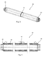
- FIG. 1 further shows that the inking roller 03 has an insertion groove 14, which encompasses the scope of the inking roller 03.
- the groove 14 is at the Ink roller 03 arranged so that they the side edges 16 of the adjacent Pressure plates 04 on the plate cylinder 02 opposite. That way, one becomes Ink transfer from the inking roller 03 on the side edges 16 of the printing plates 04 excluded, so that the side edges 16 are not printed afterwards.
- the groove 14 is bounded laterally by two bevelled flanks 17, which are at an angle ⁇ of 45 ° (FIG. 4) to the central axis 18 of the inking roller 03 extend.
- the width b of the groove 14, the distance between the transitions the flanks 17 corresponds to the peripheral surface of the inking roller 03 is smaller than that Distance a between the edges 21 of the type area 19 on the printing plates 04.
- the groove 13 has a width b in the range of 5 mm to 20 mm, in particular of 12 mm.
- the depth t of the groove 14 is 1 mm to 5 mm, in particular of about 3 mm.
- Fig. 4 shows the inking roller 03 in longitudinal section. As from the cross section in Fig. 4th can be seen, the peripheral surface of the inking roller 03 from a coating 22, in particular a rubber coating 22, produced in the groove 14th is incorporated. In addition to the groove 14, the rubber coating 22 has two more on the edge bevels 23 on the edge side edges of the two Opposed to printing plates 04.
- FIG. 5 and Fig. 6 is a second embodiment of an inking roller 24 for a moistureless working printing unit 01 shown.
- the inking roller 24 is for Use with a plate cylinder 02 provided on the four printing plates 04 are fastened next to each other.
- Two side edges of adjacent printing plates 04 is in each case a common groove 14 opposite in the Rubber coating 22 incorporated.
- On the edge are again two bevels 23rd provided for the outer side edges of the printing plates 04.
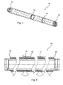
- Fig. 7 and Fig. 8 is a third embodiment of a dampening Print engine 01 shown.
- the inking roller 26 is for use with a Plate cylinder 02 is provided, are attached to the three printing plates 04, wherein the one Pressure plate 04 has twice the width. Due to the double-wide training of a pressure plate 04 eliminates a groove 14 in comparison to the structure of Inking roller 24.
Landscapes
- Inking, Control Or Cleaning Of Printing Machines (AREA)
Abstract
Description
- Fig. 1
- einen Plattenzylinder und eine Farbauftragswalze eines feuchtmittellos arbeitenden Druckwerkes in Ansicht von vorne;
- Fig. 2
- fünf Bearbeitungsschritte a) bis e) zur Herstellung der farbübertragenden Druckplatten des Druckwerks gemäß Fig. 1;
- Fig. 3
- die Farbauftragswalze zur Verwendung im Druckwerk gemäß Fig. 1 in perspektivischer Ansicht;
- Fig. 4
- die Farbauftragswalze gemäß Fig. 3 im Längsschnitt;
- Fig. 5
- eine zweite Ausführungsform einer Farbauftragswalze für ein feuchtmittellos arbeitendes Druckwerk in perspektivischer Ansicht;
- Fig. 6
- die Farbauftragswalze gemäß Fig. 5 hier im Längsschnitt;
- Fig. 7
- eine dritte Ausführungsform einer Farbauftragswalze für ein feuchtmittellos arbeitendes Druckwerk in perspektivischer Ansicht;
- Fig. 8
- die Farbauftragswalze gemäß Fig. 7 im Längsschnitt.
- 01
- Druckwerk
- 02
- Plattenzylinder
- 03
- Farbauftragswalze
- 04
- Druckplatte, Flachdruckplatte
- 05
- -
- 06
- Trägerschicht
- 07
- untere Schicht, farbannehmende Schicht, farbübertragende Schicht
- 08
- obere Schicht, farbabstoßende Schicht
- 09
- Schutzschicht
- 10
- -
- 11
- Positivfilm
- 12
- Durchbrechung
- 13
- Druckfarbe
- 14
- Nut, Einstichnut
- 15
- -
- 16
- Seitenkante
- 17
- Flanke (14)
- 18
- Mittelachse (03)
- 19
- Satzspiegel
- 20
- -
- 21
- Rand, Satzspiegelrand
- 22
- Beschichtung, Gummibeschichtung
- 23
- Abschrägung, Nut
- 24
- Farbauftragswalze
- 25
- -
- 26
- Farbauftragswalze
- α
- Winkel
- a
- Abstand
- b
- Breite (14)
- t
- Tiefe (14)
Claims (28)
- Druckwerk (01) für eine Druckmaschine ohne Feuchtwerk mit einem Plattenzylinder (02) und einer Farbauftragswalze (03), wobei der Plattenzylinder (02) in Umfangsrichtung mindestens zwei wasserlose Flachdruckplatten (04) aufweist, dadurch gekennzeichnet, dass an der Farbauftragswalze (03) mindestens eine den Umfang der Farbauftragwalze (03) umgreifende Nut (14; 23) angeordnet ist.
- Druckwerk (01) nach Anspruch 1, dadurch gekennzeichnet, dass die Nut (14; 23) einer Seitenkante (16) zumindest einer Flachdruckplatte (04) gegenüberliegt.
- Druckwerk (01) nach Anspruch 1 oder 2, dadurch gekennzeichnet, dass allen Seitenkanten (16) der auf dem Plattenzylinder (02) befestigten Flachruckplatten (04) jeweils Nuten (14; 23) an der Farbauftragswalze (03) gegenüberliegen.
- Druckwerk (01) nach Anspruch 1 bis 3, dadurch gekennzeichnet, dass die Nut (23) in der Art einer randseitigen Abschrägung (23) der Umfangsfläche der Farbauftragswalze (03) ausgebildet ist.
- Druckwerk (01) nach Anspruch 4, dadurch gekennzeichnet, dass sich die Abschrägung (23) unter einem Winkel (α) von ungefähr 45 Grad zur Mittelachse (18) der Farbauftragswalze (03) erstreckt.
- Druckwerk (01) nach Anspruch 1 oder 2, dadurch gekennzeichnet, dass die Nut (14) in der Art einer Nut (14) mit zwei seitlichen Flanken (17) ausgebildet ist.
- Druckwerk (01) nach Anspruch 6, dadurch gekennzeichnet, dass die seitlichen Flanken (17) der Nut (14) angeschrägt sind und sich unter einem Winkel (α) kleiner 90 Grad, insbesondere unter einem Winkel (α) von ungefähr 45 Grad, zur Mittelachse (18) der Farbauftragswalze (03) erstrecken.
- Druckwerk (01) nach Anspruch 6 oder 7, dadurch gekennzeichnet, dass zwei Seitenkanten (16) von benachbarten Flachdruckplatten (04) einer gemeinsamen Nut (14) gegenüberliegt.
- Druckwerk (01) nach einem der Ansprüche 1 oder 6 bis 8, dadurch gekennzeichnet, dass die Breite (b) der Nut (14) größer ist als der Abstand (a) zwischen den beiden benachbarten Flachdruckplatten (04).
- Druckwerk (01) nach einem der Ansprüche 1 oder 6 bis 9, dadurch gekennzeichnet, dass die Breite (b) der Nut (14) kleiner ist als der nicht zu druckenden Bereich des Druckbildes zwischen den Rändern (21) zweier Satzspiegel (19) von zwei nebeneinander liegender Druckseiten.
- Druckwerk (01) nach einem der Ansprüche 1 oder 6 bis 10, dadurch gekennzeichnet, dass die Nut (14) eine Breite (b) im Bereich von 5 mm bis 20 mm aufweist.
- Druckwerk (01) nach Anspruch 11, dadurch gekennzeichnet, dass die Nut (14) eine Breite (b) von ca. 12 mm aufweist.
- Druckwerk (01) nach einem der Ansprüche 6 bis 12, dadurch gekennzeichnet, dass die Nut (14) eine Tiefe (t) im Bereich von 1 mm bis 5 mm aufweist.
- Druckwerk nach Anspruch 13, dadurch gekennzeichnet, dass die Nut (14) eine Tiefe (t) von ca. 3 mm aufweist.
- Druckwerk (01) nach einem der Ansprüche 1 bis 14, dadurch gekennzeichnet, dass die Umfangsfläche der Farbauftragswalze (03) von einer Beschichtung (22),
- Druckwerk (01) nach Anspruch 15, dadurch gekennzeichnet, dass die Beschichtung (22) aus Gummi gebildet wird.
- Druckwerk nach Anspruch 15 oder 16, dadurch gekennzeichnet, dass die Nut (14; 23) in die Beschichtung (22) eingearbeitet ist.
- Druckwerk (01) nach einem der Ansprüche 1 bis 17, dadurch gekennzeichnet, dass der Plattenzylinder (02) und/oder die Farbauftragswalze (03) temperierbar ist.
- Druckwerk (01) nach Anspruch 18, dadurch gekennzeichnet, dass der Plattenzylinder (02) und/oder die Farbauftragswalze (03) von innen temperierbar ist.
- Druckwerk (01) nach Anspruch 18 oder 19, dadurch gekennzeichnet, dass der Plattenzylinder (02) und/oder die Farbauftragswalze (03) mittels einer Flüssigkeit temperierbar ist.
- Druckwerk (01) nach einem der Ansprüche 18 bis 20, dadurch gekennzeichnet, dass die Temperierung des Plattenzylinders (02) und/oder der Farbauftragswalze (03) von der Umfangsgeschwindigkeit des Plattenzylinders (02) und/oder der Umfangsgeschwindigkeit der Farbauftragswalze (03) abhängt.
- Druckwerk nach Anspruch 1, dadurch gekennzeichnet, dass die Flachdruckplatte (04) eine Beschichtung (22) aufweist.
- Druckwerk nach Anspruch 22, dadurch gekennzeichnet, dass die Beschichtung (22) eine untere Schicht (07) und eine obere Schicht (08) aufweist.
- Druckwerk nach Anspruch 23, dadurch gekennzeichnet, dass die untere Schicht (07) aus einem farbannehmenden Material besteht.
- Druckwerk nach Anspruch 23, dadurch gekennzeichnet, dass die obere Schicht (08) aus einem farbabstoßenden Material besteht.
- Druckwerk nach Anspruch 25, dadurch gekennzeichnet, dass das farbabstoßende Material ein silikonhaltiges Material ist.
- Druckwerk nach Anspruch 23, dadurch gekennzeichnet, dass die obere Schicht (08) an den zu druckenden Bereichen Durchbrechungen aufweist.
- Druckwerk nach Anspruch 23, dadurch gekennzeichnet, dass die obere Schicht (08) die untere Schicht (07) abdeckt.
Applications Claiming Priority (2)
| Application Number | Priority Date | Filing Date | Title |
|---|---|---|---|
| DE102004011881 | 2004-03-11 | ||
| DE200410011881 DE102004011881B3 (de) | 2004-03-11 | 2004-03-11 | Druckwerk für eine Druckmaschine ohne Feuchtwerk |
Publications (1)
| Publication Number | Publication Date |
|---|---|
| EP1574338A1 true EP1574338A1 (de) | 2005-09-14 |
Family
ID=34442582
Family Applications (1)
| Application Number | Title | Priority Date | Filing Date |
|---|---|---|---|
| EP04105993A Withdrawn EP1574338A1 (de) | 2004-03-11 | 2004-11-23 | Druckwerk für eine Druckmaschine ohne Feuchtwerk |
Country Status (2)
| Country | Link |
|---|---|
| EP (1) | EP1574338A1 (de) |
| DE (1) | DE102004011881B3 (de) |
Citations (5)
| Publication number | Priority date | Publication date | Assignee | Title |
|---|---|---|---|---|
| DE3705194A1 (de) | 1987-02-19 | 1988-09-01 | Frankenthal Ag Albert | Farbwerk |
| US5598777A (en) | 1995-10-02 | 1997-02-04 | Howard W. DeMoore | Retractable printing/coating unit operable on the plate and blanket cylinders |
| DE29623426U1 (de) * | 1996-12-20 | 1998-05-28 | Koenig & Bauer-Albert Aktiengesellschaft, 97080 Würzburg | Walze |
| DE19718549A1 (de) * | 1997-05-02 | 1998-11-05 | Druck Und Verlagshaus Frankfur | Druckmaschine |
| WO2003045695A1 (de) | 2001-11-22 | 2003-06-05 | Koenig & Bauer Aktiengesellschaft | Verfahren zum betrieb eines druckwerkes und verwendung einer druckfarbe |
-
2004
- 2004-03-11 DE DE200410011881 patent/DE102004011881B3/de not_active Revoked
- 2004-11-23 EP EP04105993A patent/EP1574338A1/de not_active Withdrawn
Patent Citations (5)
| Publication number | Priority date | Publication date | Assignee | Title |
|---|---|---|---|---|
| DE3705194A1 (de) | 1987-02-19 | 1988-09-01 | Frankenthal Ag Albert | Farbwerk |
| US5598777A (en) | 1995-10-02 | 1997-02-04 | Howard W. DeMoore | Retractable printing/coating unit operable on the plate and blanket cylinders |
| DE29623426U1 (de) * | 1996-12-20 | 1998-05-28 | Koenig & Bauer-Albert Aktiengesellschaft, 97080 Würzburg | Walze |
| DE19718549A1 (de) * | 1997-05-02 | 1998-11-05 | Druck Und Verlagshaus Frankfur | Druckmaschine |
| WO2003045695A1 (de) | 2001-11-22 | 2003-06-05 | Koenig & Bauer Aktiengesellschaft | Verfahren zum betrieb eines druckwerkes und verwendung einer druckfarbe |
Also Published As
| Publication number | Publication date |
|---|---|
| DE102004011881B3 (de) | 2005-05-19 |
Similar Documents
| Publication | Publication Date | Title |
|---|---|---|
| EP0078444B1 (de) | Farbwerk für Offsetdruckmaschinen | |
| EP0225509B1 (de) | Vorrichtung zum Bedrucken einer Bahn | |
| DE1471694C3 (de) | Druckmaschine, insbesondere für den Wertpapierdruck | |
| DE3109964C2 (de) | ||
| DE3336193C2 (de) | Gummituch für eine Offsetrotationsdruckmaschine | |
| EP1694505B1 (de) | Drucktuch mit einer formstabilen trägerplatte und verfahren zur herstellung eines solchen drucktuches | |
| DE60010354T2 (de) | Gummituch mit variabelen Oberflächeneigenschaften für eine Druckmaschine | |
| CH668225A5 (de) | Mehrfarbenrotationsdruckmaschine zum gleichzeitigen schoen- und widerdruck. | |
| EP0771267B1 (de) | Druckwerk mit kurzfarbwerk einer rotationsdruckmaschine für direktdruck mittels einer "wasserlosen" flachdruckplatte | |
| EP1457331B1 (de) | Kurzfarbwerk einer Rotationsdruckmaschine | |
| EP0518892B1 (de) | Kurzfarbwerk für eine rollenrotationsdruckmaschine | |
| DE435902C (de) | Rotationsgummidruckmaschine zur Herstellung von mehrfarbigem Schoen- und Widerdruck fuer veraenderliche Druckbogengroessen | |
| DE2435251A1 (de) | Verfahren und vorrichtung zum herstellen eines mehrfarbigen offsetdruckes | |
| EP0428894B1 (de) | Verfahren zur Druckvorbereitung eines Druckwerks und dazu verwendbares Druckwerk | |
| DE3412783C2 (de) | Druckwerk einer Rollen-Rotations-Offsetdruckmaschine | |
| DE102012013532B4 (de) | Einrichtung zum Drucken mit weich-elastischen Druckformen | |
| DE102004011881B3 (de) | Druckwerk für eine Druckmaschine ohne Feuchtwerk | |
| DE3705194A1 (de) | Farbwerk | |
| DE102004011882A1 (de) | Druckwerk für eine Druckmaschine ohne Feuchtwerk sowie Drucktuch | |
| DE102004023316A1 (de) | Drucktuch mit einer formstabilen Trägerplatte, ein Verfahren zur Herstellung eines solchen Drucktuches sowie ein Druckwerk für eine Druckmaschine ohne Feuchtwerk | |
| AT527433B1 (de) | Druckvorrichtung | |
| DE29510929U1 (de) | Druckwerk mit Kurzfarbwerk einer Rotationsdruckmaschine für Direktdruck mittels einer wasserlosen Flachdruckplatte | |
| DE102022128546A1 (de) | Druckvorrichtung für den Irisdruck | |
| DE102022128544A1 (de) | Druckvorrichtung und Druckverfahren für eine mehrfarbige Nummerierung | |
| DE10241739A1 (de) | Mehrfarben-Druckwerk |
Legal Events
| Date | Code | Title | Description |
|---|---|---|---|
| PUAI | Public reference made under article 153(3) epc to a published international application that has entered the european phase |
Free format text: ORIGINAL CODE: 0009012 |
|
| 17P | Request for examination filed |
Effective date: 20050701 |
|
| AK | Designated contracting states |
Kind code of ref document: A1 Designated state(s): AT BE BG CH CY CZ DE DK EE ES FI FR GB GR HU IE IS IT LI LU MC NL PL PT RO SE SI SK TR |
|
| AX | Request for extension of the european patent |
Extension state: AL HR LT LV MK YU |
|
| AKX | Designation fees paid |
Designated state(s): AT BE BG CH CY CZ DE DK EE ES FI FR GB GR HU IE IS IT LI LU MC NL PL PT RO SE SI SK TR |
|
| 17Q | First examination report despatched |
Effective date: 20081007 |
|
| STAA | Information on the status of an ep patent application or granted ep patent |
Free format text: STATUS: THE APPLICATION HAS BEEN WITHDRAWN |
|
| 18W | Application withdrawn |
Effective date: 20090522 |