EP1574263A2 - Appareil pour la préparation des revêtements biomimétiques sur un implant médical - Google Patents
Appareil pour la préparation des revêtements biomimétiques sur un implant médical Download PDFInfo
- Publication number
- EP1574263A2 EP1574263A2 EP05251347A EP05251347A EP1574263A2 EP 1574263 A2 EP1574263 A2 EP 1574263A2 EP 05251347 A EP05251347 A EP 05251347A EP 05251347 A EP05251347 A EP 05251347A EP 1574263 A2 EP1574263 A2 EP 1574263A2
- Authority
- EP
- European Patent Office
- Prior art keywords
- reactor
- biomimetic
- reactors
- inner reactor
- flow control
- Prior art date
- Legal status (The legal status is an assumption and is not a legal conclusion. Google has not performed a legal analysis and makes no representation as to the accuracy of the status listed.)
- Granted
Links
Images




Classifications
-
- B—PERFORMING OPERATIONS; TRANSPORTING
- B05—SPRAYING OR ATOMISING IN GENERAL; APPLYING FLUENT MATERIALS TO SURFACES, IN GENERAL
- B05C—APPARATUS FOR APPLYING FLUENT MATERIALS TO SURFACES, IN GENERAL
- B05C3/00—Apparatus in which the work is brought into contact with a bulk quantity of liquid or other fluent material
- B05C3/005—Apparatus in which the work is brought into contact with a bulk quantity of liquid or other fluent material incorporating means for heating or cooling the liquid or other fluent material
-
- B—PERFORMING OPERATIONS; TRANSPORTING
- B05—SPRAYING OR ATOMISING IN GENERAL; APPLYING FLUENT MATERIALS TO SURFACES, IN GENERAL
- B05C—APPARATUS FOR APPLYING FLUENT MATERIALS TO SURFACES, IN GENERAL
- B05C3/00—Apparatus in which the work is brought into contact with a bulk quantity of liquid or other fluent material
- B05C3/02—Apparatus in which the work is brought into contact with a bulk quantity of liquid or other fluent material the work being immersed in the liquid or other fluent material
- B05C3/09—Apparatus in which the work is brought into contact with a bulk quantity of liquid or other fluent material the work being immersed in the liquid or other fluent material for treating separate articles
- B05C3/109—Passing liquids or other fluent materials into or through chambers containing stationary articles
-
- A—HUMAN NECESSITIES
- A61—MEDICAL OR VETERINARY SCIENCE; HYGIENE
- A61C—DENTISTRY; APPARATUS OR METHODS FOR ORAL OR DENTAL HYGIENE
- A61C8/00—Means to be fixed to the jaw-bone for consolidating natural teeth or for fixing dental prostheses thereon; Dental implants; Implanting tools
- A61C8/0012—Means to be fixed to the jaw-bone for consolidating natural teeth or for fixing dental prostheses thereon; Dental implants; Implanting tools characterised by the material or composition, e.g. ceramics, surface layer, metal alloy
-
- A—HUMAN NECESSITIES
- A61—MEDICAL OR VETERINARY SCIENCE; HYGIENE
- A61F—FILTERS IMPLANTABLE INTO BLOOD VESSELS; PROSTHESES; DEVICES PROVIDING PATENCY TO, OR PREVENTING COLLAPSING OF, TUBULAR STRUCTURES OF THE BODY, e.g. STENTS; ORTHOPAEDIC, NURSING OR CONTRACEPTIVE DEVICES; FOMENTATION; TREATMENT OR PROTECTION OF EYES OR EARS; BANDAGES, DRESSINGS OR ABSORBENT PADS; FIRST-AID KITS
- A61F2/00—Filters implantable into blood vessels; Prostheses, i.e. artificial substitutes or replacements for parts of the body; Appliances for connecting them with the body; Devices providing patency to, or preventing collapsing of, tubular structures of the body, e.g. stents
- A61F2/02—Prostheses implantable into the body
- A61F2/28—Bones
-
- A—HUMAN NECESSITIES
- A61—MEDICAL OR VETERINARY SCIENCE; HYGIENE
- A61F—FILTERS IMPLANTABLE INTO BLOOD VESSELS; PROSTHESES; DEVICES PROVIDING PATENCY TO, OR PREVENTING COLLAPSING OF, TUBULAR STRUCTURES OF THE BODY, e.g. STENTS; ORTHOPAEDIC, NURSING OR CONTRACEPTIVE DEVICES; FOMENTATION; TREATMENT OR PROTECTION OF EYES OR EARS; BANDAGES, DRESSINGS OR ABSORBENT PADS; FIRST-AID KITS
- A61F2/00—Filters implantable into blood vessels; Prostheses, i.e. artificial substitutes or replacements for parts of the body; Appliances for connecting them with the body; Devices providing patency to, or preventing collapsing of, tubular structures of the body, e.g. stents
- A61F2/02—Prostheses implantable into the body
- A61F2/30—Joints
- A61F2/30767—Special external or bone-contacting surface, e.g. coating for improving bone ingrowth
-
- A—HUMAN NECESSITIES
- A61—MEDICAL OR VETERINARY SCIENCE; HYGIENE
- A61F—FILTERS IMPLANTABLE INTO BLOOD VESSELS; PROSTHESES; DEVICES PROVIDING PATENCY TO, OR PREVENTING COLLAPSING OF, TUBULAR STRUCTURES OF THE BODY, e.g. STENTS; ORTHOPAEDIC, NURSING OR CONTRACEPTIVE DEVICES; FOMENTATION; TREATMENT OR PROTECTION OF EYES OR EARS; BANDAGES, DRESSINGS OR ABSORBENT PADS; FIRST-AID KITS
- A61F2/00—Filters implantable into blood vessels; Prostheses, i.e. artificial substitutes or replacements for parts of the body; Appliances for connecting them with the body; Devices providing patency to, or preventing collapsing of, tubular structures of the body, e.g. stents
- A61F2/02—Prostheses implantable into the body
- A61F2/30—Joints
- A61F2/3094—Designing or manufacturing processes
-
- A—HUMAN NECESSITIES
- A61—MEDICAL OR VETERINARY SCIENCE; HYGIENE
- A61F—FILTERS IMPLANTABLE INTO BLOOD VESSELS; PROSTHESES; DEVICES PROVIDING PATENCY TO, OR PREVENTING COLLAPSING OF, TUBULAR STRUCTURES OF THE BODY, e.g. STENTS; ORTHOPAEDIC, NURSING OR CONTRACEPTIVE DEVICES; FOMENTATION; TREATMENT OR PROTECTION OF EYES OR EARS; BANDAGES, DRESSINGS OR ABSORBENT PADS; FIRST-AID KITS
- A61F2310/00—Prostheses classified in A61F2/28 or A61F2/30 - A61F2/44 being constructed from or coated with a particular material
- A61F2310/00005—The prosthesis being constructed from a particular material
- A61F2310/00011—Metals or alloys
- A61F2310/00017—Iron- or Fe-based alloys, e.g. stainless steel
-
- A—HUMAN NECESSITIES
- A61—MEDICAL OR VETERINARY SCIENCE; HYGIENE
- A61F—FILTERS IMPLANTABLE INTO BLOOD VESSELS; PROSTHESES; DEVICES PROVIDING PATENCY TO, OR PREVENTING COLLAPSING OF, TUBULAR STRUCTURES OF THE BODY, e.g. STENTS; ORTHOPAEDIC, NURSING OR CONTRACEPTIVE DEVICES; FOMENTATION; TREATMENT OR PROTECTION OF EYES OR EARS; BANDAGES, DRESSINGS OR ABSORBENT PADS; FIRST-AID KITS
- A61F2310/00—Prostheses classified in A61F2/28 or A61F2/30 - A61F2/44 being constructed from or coated with a particular material
- A61F2310/00005—The prosthesis being constructed from a particular material
- A61F2310/00011—Metals or alloys
- A61F2310/00023—Titanium or titanium-based alloys, e.g. Ti-Ni alloys
-
- A—HUMAN NECESSITIES
- A61—MEDICAL OR VETERINARY SCIENCE; HYGIENE
- A61F—FILTERS IMPLANTABLE INTO BLOOD VESSELS; PROSTHESES; DEVICES PROVIDING PATENCY TO, OR PREVENTING COLLAPSING OF, TUBULAR STRUCTURES OF THE BODY, e.g. STENTS; ORTHOPAEDIC, NURSING OR CONTRACEPTIVE DEVICES; FOMENTATION; TREATMENT OR PROTECTION OF EYES OR EARS; BANDAGES, DRESSINGS OR ABSORBENT PADS; FIRST-AID KITS
- A61F2310/00—Prostheses classified in A61F2/28 or A61F2/30 - A61F2/44 being constructed from or coated with a particular material
- A61F2310/00005—The prosthesis being constructed from a particular material
- A61F2310/00011—Metals or alloys
- A61F2310/00029—Cobalt-based alloys, e.g. Co-Cr alloys or Vitallium
-
- A—HUMAN NECESSITIES
- A61—MEDICAL OR VETERINARY SCIENCE; HYGIENE
- A61F—FILTERS IMPLANTABLE INTO BLOOD VESSELS; PROSTHESES; DEVICES PROVIDING PATENCY TO, OR PREVENTING COLLAPSING OF, TUBULAR STRUCTURES OF THE BODY, e.g. STENTS; ORTHOPAEDIC, NURSING OR CONTRACEPTIVE DEVICES; FOMENTATION; TREATMENT OR PROTECTION OF EYES OR EARS; BANDAGES, DRESSINGS OR ABSORBENT PADS; FIRST-AID KITS
- A61F2310/00—Prostheses classified in A61F2/28 or A61F2/30 - A61F2/44 being constructed from or coated with a particular material
- A61F2310/00005—The prosthesis being constructed from a particular material
- A61F2310/00011—Metals or alloys
- A61F2310/00035—Other metals or alloys
- A61F2310/00089—Zirconium or Zr-based alloys
-
- A—HUMAN NECESSITIES
- A61—MEDICAL OR VETERINARY SCIENCE; HYGIENE
- A61F—FILTERS IMPLANTABLE INTO BLOOD VESSELS; PROSTHESES; DEVICES PROVIDING PATENCY TO, OR PREVENTING COLLAPSING OF, TUBULAR STRUCTURES OF THE BODY, e.g. STENTS; ORTHOPAEDIC, NURSING OR CONTRACEPTIVE DEVICES; FOMENTATION; TREATMENT OR PROTECTION OF EYES OR EARS; BANDAGES, DRESSINGS OR ABSORBENT PADS; FIRST-AID KITS
- A61F2310/00—Prostheses classified in A61F2/28 or A61F2/30 - A61F2/44 being constructed from or coated with a particular material
- A61F2310/00005—The prosthesis being constructed from a particular material
- A61F2310/00011—Metals or alloys
- A61F2310/00035—Other metals or alloys
- A61F2310/00095—Niobium or Nb-based alloys
-
- A—HUMAN NECESSITIES
- A61—MEDICAL OR VETERINARY SCIENCE; HYGIENE
- A61F—FILTERS IMPLANTABLE INTO BLOOD VESSELS; PROSTHESES; DEVICES PROVIDING PATENCY TO, OR PREVENTING COLLAPSING OF, TUBULAR STRUCTURES OF THE BODY, e.g. STENTS; ORTHOPAEDIC, NURSING OR CONTRACEPTIVE DEVICES; FOMENTATION; TREATMENT OR PROTECTION OF EYES OR EARS; BANDAGES, DRESSINGS OR ABSORBENT PADS; FIRST-AID KITS
- A61F2310/00—Prostheses classified in A61F2/28 or A61F2/30 - A61F2/44 being constructed from or coated with a particular material
- A61F2310/00005—The prosthesis being constructed from a particular material
- A61F2310/00011—Metals or alloys
- A61F2310/00035—Other metals or alloys
- A61F2310/00131—Tantalum or Ta-based alloys
-
- A—HUMAN NECESSITIES
- A61—MEDICAL OR VETERINARY SCIENCE; HYGIENE
- A61F—FILTERS IMPLANTABLE INTO BLOOD VESSELS; PROSTHESES; DEVICES PROVIDING PATENCY TO, OR PREVENTING COLLAPSING OF, TUBULAR STRUCTURES OF THE BODY, e.g. STENTS; ORTHOPAEDIC, NURSING OR CONTRACEPTIVE DEVICES; FOMENTATION; TREATMENT OR PROTECTION OF EYES OR EARS; BANDAGES, DRESSINGS OR ABSORBENT PADS; FIRST-AID KITS
- A61F2310/00—Prostheses classified in A61F2/28 or A61F2/30 - A61F2/44 being constructed from or coated with a particular material
- A61F2310/00005—The prosthesis being constructed from a particular material
- A61F2310/00179—Ceramics or ceramic-like structures
Definitions
- This invention pertains to a coating for an implantable article, and more particularly, to an apparatus and method for producing a coating on an implantable article.
- Mineralized and/or ceramic coatings are applied to a variety of articles.
- such coatings are frequently applied to biological implants (e.g., medical implants).
- biological implants e.g., medical implants
- the coating is usually applied to a metal or plastic substrate, but the coating can be applied to other substrates as well such as ceramic and silicon.
- Biological implants such as joint and dental prostheses, usually must be permanently affixed or anchored within bone.
- a bone cement to affix the prosthesis within bone.
- the bone-to-implant interfaces that result from natural bone ingrowth tend to be stronger over time and more permanent than are bone cement-prosthesis bonds.
- various materials including titanium alloys, are biocompatible, they are not necessarily bioactive because they can neither induce bone formation nor form chemical bonds with bone.
- providing irregular beaded or porous surfaces on the implant can enhance bone ingrowth and prosthesis fixation.
- coating the implant with a bioactive mineralized and/or ceramic material can attain enhanced fixation of implants within bone. Such coatings have been shown to encourage more rapid bone ingrowth in and around the prosthesis. The ability of such coatings to induce bone formation can be improved by incorporating a biological agent into the bores of the ceramic coating.
- the invention provides an apparatus for producing a biomimetic coating on an implantable article.
- the apparatus includes an outer reactor for containing a biomimetic coating solution and an inner reactor arranged within the outer reactor.
- the inner reactor is smaller than the outer reactor so as to define a space between the inner and outer reactors.
- the apparatus also includes a pump system for circulating the biomimetic coating solution.
- the pump system is arranged to operate in the space between the inner and outer reactors.
- the inner reactor includes a flow control system that is selectively operable to control the flow of biomimetic coating solution between the outer and inner reactors.
- the invention further provides a method for producing a biomimetic coating on an implantable article.
- the method includes the step of filling an outer reactor and an inner reactor arranged within the outer reactor with a biomimetic coating solution.
- a flow control system associated with the inner reactor is moved to an open position so as to permit unrestrained flow of biomimetic coating solution between the outer and inner reactors.
- the biomimetic coating solution is mixed and heated to a desired homogeneity and temperature through a pump system that operates in a space between the outer and inner reactors.
- An implantable article is inserted in the inner reactor and the flow control system associated with the inner reactor is moved to a closed position so as to limit flow of biomimetic between the outer and inner reactors.
- FIG. 1 is a perspective view of an illustrative apparatus for applying a biomimetic coating on an implantable article in accordance with the invention.
- FIG. 2 is a side view of the coating apparatus of FIG. 1.
- FIG. 3 is another side view of the coating apparatus of FIG. 1.
- FIG. 4 is a top view of the coating apparatus of FIG. 1.
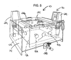
- FIG. 5 is a perspective view of the coating apparatus of FIG. 1 showing some of the flow control apertures closed by stoppers.
- FIG. 6 is a perspective view of an alternative embodiment of a coating apparatus according to the present invention.
- FIG. 7 is a perspective view of the coating apparatus of FIG. 6 showing one of the inner reactor walls partially removed.
- an illustrative apparatus 10 for producing a coating on a substrate, in this case an implantable article, in accordance with the present invention is shown. More specifically, and as described in greater detail below, the illustrative apparatus 10 is capable of producing biomimetic coatings, such as for example a biomimetic apatite coating, on implantable articles. Specific details regarding such coatings and methods for preparing such coatings can be found in commonly owned U.S. Application Ser. No. 10/355,827, the disclosure of which is incorporated herein by reference.
- the composition used to form the biomimetic coating is in solution form.
- the solution can comprise the various chemical components suspended or dissolved in a liquid carrier.
- the chemical components could include a biological agent that would improve the ability of the ability of the coating to induce or conduct bone formation.
- the composition could include a biological agent, calcium ions, phosphate ions and a liquid carrier.
- the liquid carrier can be any suitable aqueous or non-aqueous liquid in which the necessary chemical components for forming the bioactive surface or ceramic coating can be suspended or dissolved for delivery to the implantable article or other substrate.
- suitable liquid carriers include, water, tris-buffered saline, phosphate-buffered saline, and the like.
- the process for producing the biomimetic coating generally includes a solution preparation phase and a coating formation phase.
- the various chemicals that make up the particular composition that will be used to form biomimetic coating are mixed together and heated to the desired temperature.
- the substrates to be coated, in this case implantable articles, are then added.
- the implantable articles are then incubated in the solution for a period of time.
- the incubation time can be any suitable or desired period of time, including up to 24 hours or more or even 72 hours or more.
- the incubation can take place at any suitable temperature necessary for properly preparing the biomimetic coating. For example, the incubation could take place at between about 30°C and about 50°C.
- the implantable articles can be removed from the solution. Additional processing steps could include rinsing and/or drying of the implantable articles. As noted above, specific details regarding the composition of the solution and the coating process can be found in commonly owned U.S. Application Ser. No. 10/355,827.
- the illustrated apparatus 10 permits the circulation and temperature of the biomimetic coating material, such as biomimetic apatite coating material, to be tightly controlled during both the solution preparation and coating formation stages of the process. Without such tight control, the coating formed on the implantable articles can be very uneven with areas where the coating is too thin or nonexistent and areas where the coating is too thick and blocks the porous structure.
- the biomimetic coating material such as biomimetic apatite coating material
- the coating apparatus 10 includes inner and outer reactors 12, 14 and an associated pump system 16.
- the outer reactor 14 protects the integrity of the coating solution and helps maintain the temperature of the solution.
- the outer reactor 14 has a generally rectangular configuration including two pairs of opposing sidewalls 18, a bottom wall 20 and an open top (see, e.g., FIG. 1).
- the outer reactor 14 can have any suitable or desired configuration.
- the outer reactor should be large enough to hold the desired amount of solution.
- the outer reactor has a 110 liter capacity.
- the open top of the outer reactor 14 can be large enough to allow for removal of the inner reactor 12 and/or to provide access to the inner reactor 12 for cleaning.
- the opening in the top of the outer reactor 14 can also be large enough to allow for manual placement of the medical implants in the inner reactor 12.
- the open top of the outer reactor can be covered by a removable lid 22 that sits firmly on the top of the outer reactor 14 in order to prevent excess evaporation of the solution.
- the removable outer reactor lid 22 can have one or more apertures 24 therein (see, e.g., FIG. 4).
- the apertures 24 in the lid 22 can also be used to introduce or remove solution from the reactors 12, 14 without removing the entire lid.
- the outer reactor 14 can be constructed of any suitable material including polymers or metals that can withstand the required temperatures for an extended period of time. Moreover, the material used to construct the outer reactor 14 should be strong enough to support the weight of the solution and inner reactor 12. Similarly, the lid 22 can be made of any suitable material (polymers, metals, etc.) that is capable of withstanding the required temperature for a prolonged period of time without warping.
- the outer reactor 14 can be equipped with a drainage system including a drain and a drain valve 28.
- the drain valve 28 can be manually operable and when opened would allow the solution to drain from the outer reactor 14 through a drain line to a sink or other receptacle for the used solution.
- the drain should be large enough to empty the reactors at a reasonable rate. However, the drain should be small enough to ensure that excess liquid does not collect in the tubing between the drain and the drain valve 28. All the liquid in the reactors and the drain line either from the coating process or a cleaning operation should be drained completely to prevent future coating processes from becoming contaminated.
- the pump system 16 essentially controls the apparatus and the coating process by controlling the temperature and circulation rate of the biomimetic coating solution throughout the solution preparation phase and the coating formation phase.
- the pump system 16 is provided on the outer reactor 14. More particularly, the illustrated coating apparatus 10 includes two pump units 29 each of which is mounted on a corresponding bridge 30 that rests on the top of the outer reactor 14. These pump units 29 control the circulation of the biomimetic coating solution within the apparatus 10 so as to ensure that the chemicals are thoroughly mixed during the solution preparation phase and the homogeneity and temperature of the coating solution is maintained during the coating formation phase.
- each of the pump units 29 comprises an electronically controlled immersion thermostat having an integrated pump.
- the illustrated pump units 29 can be setup so as to maintain the biomimetic coating solution at a set temperature and circulation rate during the solution preparation phase and again during the coating preparation phase.
- Each pump unit 29 has a heating coil 32 that extends downward into the outer reactor and a pump housing 34 which is also disposed inside the outer reactor 14 (see FIGS. 1 and 2). The heating coils 32 heat the biomimetic coating solution in the apparatus while the pump housings 34 provide the circulation of the solution in the apparatus 10.
- a discharge tube 36 is also connected to the pump housing 34 of each of the pump units 29.
- These discharge tubes 36 extend downward inside the outer reactor 14 to weighted blocks 38 arranged at the bottom of the outer reactor 14 so as to direct the pump discharge along one of the sidewalls 18 of the outer reactor 14.
- the illustrated pump units 29 also include outlet lines 42 that extend into the outer reactor 14 and that can be used to introduce gases into the system via corresponding inlet lines.
- a suitable pump unit for use in the apparatus of the present invention is the Ecoline E 100 immersion thermostat with integrated pump available from Lauda of Germany. Of course, any suitable pump and thermostat could be used.
- the inner reactor 12 sits within the outer reactor 14 and receives and holds the implantable articles during the coating process.
- a positioner or platform (not shown) can be provided in the inner reactor 12 to support the implantable articles.
- the inner reactor 12 serves as a buffer to protect the implantable articles being coated from turbulence caused by the pump system 16.
- the individual pump units 29 are arranged so as to operate within the space between in the inner and outer reactors 12, 14.
- the heating coil 32, pump housing 34, discharge tube 36 and outlet line 42 associated with each of the pump units 29 is arranged in and operates in the area between the sidewalls of the inner and outer reactors 12, 14. This arrangement helps insulate the implantable articles from turbulence or other forces caused by operation of the pump system 16.
- the inner reactor 12 has a generally rectangular configuration consisting of two pairs of opposing sidewalls 44, a bottom wall 46 and an open top that can be closed with a lid 47 (see FIGS. 1-3).
- Each of the sidewalls 44 of the inner reactor 12 extends parallel to and is shorter in length than a corresponding sidewall 18 of the outer reactor 14.
- the inner reactor 12 is shorter in height than the outer reactor 14 and is supported on legs 48 that space the bottom wall 46 of the inner reactor 12 above the bottom wall 20 of the outer reactor 14. As a result, space is provided between the inner and outer reactors 12, 14 on all sides of the inner reactor including above and below the inner reactor.
- the inner reactor can have any desired configuration and that the space between the inner and outer reactors can also have any desired configuration.
- the lid 47 of the inner reactor 12 can be selectively removable.
- the lid 47 fits firmly on the top of the inner reactor 12 so that the lid will not moved as a result of circulation of the biomimetic coating solution during the coating process.
- the inner reactor lid 47 has a plurality of apertures 50 formed therein (see FIG. 1). These apertures 50 allow circulation of the biomimetic coating solution between the inner and outer reactors 12, 14. Moreover, these apertures 50 can be made large enough to allow external devices such as electrodes or temperature probes to have access to the solution in the inner reactor 12.
- the apertures 50 in the inner reactor lid 47 also provide access for removal and/or addition of biomimetic coating solution to and/or from the inner reactor 12 without disturbing the lid during the coating process.
- the inner reactor 12 can be constructed of any suitable material including polymers or metals that can withstand the required temperatures for an extended period of time. Moreover, the material used to construct the inner reactor should be strong enough to support the weight of the solution. Likewise, the lid 47 of the inner reactor 12 can be made of any suitable material (polymers, metals, etc.) that is capable of withstanding the required temperature for a prolonged period of time without warping.
- the inner reactor 12 can be configured with a selectively adjustable or closable flow control system that permits the flow between the inner and outer reactors 12, 14 to be selectively adjusted. It is generally preferable that there be more circulation of the biomimetic coating solution in the inner reactor 12 in the solution preparation phase and early coating formation phase than in the later stages of the coating formation phase.
- the inner reactor 12 is configured so that the flow between the inner and outer reactors 12, 14 is reduced during the late stages of coating formation. This reduces the circulation of the coating solution in the inner reactor 12 thereby enhancing late stage coating formation.
- the flow control between the inner and outer reactors 12, 14 is achieved by providing selectively closable apertures 52 in the walls of the inner reactor.
- one or more apertures 52 can be provided in one or more of the sidewalls 44 of the inner reactor 12.
- Each of these apertures 52 can be selectively opened or closed by a closure device such as a tapered stopper 53 as shown in FIG. 5.
- a plurality of apertures 52 are provided in each of the sidewalls 44 of the inner reactor 12 and in the bottom wall 46 of the reactor.
- the apertures in the bottom wall 46 of the inner rector are also used in draining the system.
- the lid 47 of the inner reactor 12 also has a plurality of apertures 50 therein.
- the number, size and configuration of the apertures can vary depending upon the degree of control over the flow between the reactors that is desired.
- the majority if not all of the flow control apertures 52 in the inner reactor 12 are left open to allow for sufficient mixing of the chemicals that make up the biomimetic coating solution (see FIGS. 1-3). Later in the coating process, these flow control apertures 52 can be selectively closed so as to limit the flow between the outer and inner reactor 14, 12 and thereby reduce the circulation of the biomimetic coating solution in the inner reactor 12.
- the flow control apertures 52 can be closed using separate stoppers 53 that can be plugged into the apertures 52 as desired (see FIG. 5). The number of apertures 52 that are plugged closed can vary depending on the desired circulation in the inner reactor 12.
- the flow control apertures 52 in the inner reactor 12 are left open so as to ensure sufficient circulation to maintain the temperature and homogeneity of the solution.
- the apertures in the lid 47 and bottom wall 46 of the inner reactor 12 are typically always left open.
- the flow between the inner and outer reactors 12, 14 can be controlled in different ways and the present invention is not limited to any particular flow control system or type of flow control element.
- an alternative embodiment of an inner reactor 12 having a different flow control system is illustrated in FIGS. 6 and 7.
- the inner reactor 12 has a modular construction in which the sidewalls 54 can be easily removed and replaced from the reactor.
- the inner reactor 12 can be constructed with corner elements that define slots 56 for receiving the contiguous edges of the walls 54 defining that corner. These slots allow the walls 54 to be selectively slid into and out of place. For example, in the solution preparation phase, the walls 54 would be completely removed or slid partially up into an open position so as to maximize mixing of the solution.
- the solid walls 54 would then be slid into place or closed during the coating formation stage in order to limit the flow between the inner and outer reactors 12, 15. Some openings or other means would still have to be provided in the inner reactor 12, in this case openings in the lid and bottom wall, to permit sufficient circulation to maintain the temperature and homogeneity of the solution when the walls 54 were closed.
- the lids 22, 47 of the inner and outer reactors 12, 14 would be removed, and the chemicals making up the biomimetic coating solution would then be added to the reactors. This initial addition could be done by hand or as a part of an automated process.
- the pump system 16 would then be used to mix and heat the chemicals to prepare the biomimetic coating solution.
- all of the flow control apertures 52 in the inner reactor 12 would be open or, in the case of the FIGS. 6 and 7 embodiment, the walls 54 would be raised or removed.
- some or all of the flow control apertures 52 in the inner reactor 12 can be closed to limit the flow between the inner and outer reactors 12, 14.
- the walls 54 could be slid into place.
- the pump system 16 would continue to operate and at least some of the flow control apertures 52 in the inner reactor 12 would remain open to maintain the temperature and homogeneity of the coating solution in the inner reactor 12.
- the implantable articles can be removed from the inner reactor 12 and subjected to any needed subsequent processing steps such as rinsing or drying.
- the coating solution can be drained from the inner and outer reactors, which can then be cleaned for reuse.
- bioactive means having the ability to effect local tissue activity, for instance, by improving local bone formation or by preventing the onset and proliferation of microbial species.
- implantable article refers to any object or device that can be inserted or embedded into or grafted onto a body, or any part thereof, and that is designed for biomedical use.
- the implantable article for example, can be a bone substitute, a joint prosthesis, a dental implant (prosthodontics), a maxillofacial implant, a vertebral surgery aid, a transcutaneous device (stoma or the like), or other medical or cosmetic device.
- Such implantable articles can serve as a bone replacement or bone reinforcement, as well as a means of fixing a device to a particular bone.
- biocompatible substrate any object or device that is compatible with the body into which the object or device is inserted or embedded or with the body onto which the object or device is grafted, such that the object or device will not cause an adverse immune response in the body.
- the biocompatible substrate can comprise any suitable material(s), such as silicon, metals, ceramics, or polymers.
- Biocompatible metals include titanium, tantalum, niobium, zirconium, and alloys thereof (e.g., titanium alloys and tantalum alloys), as well as cobalt-chromium alloys and stainless steel.
- Biocompatible polymers can be natural or synthetic polymers, such as polyethylene (e.g., ultrahigh molecular weight polyethylene or polyethylene oxide), polypropylene, polytetrafluoroethylene, polyglycolic acid, polylactic acid, other polysaccharides, and copolymers of any of the foregoing (e.g., copolymers of polylactic acid and polyglycol acid).
- the biocompatible substrate comprises, consists essentially of, or consists of a biocompatible metal. More preferably, the biocompatible substrate comprises, consists essentially of, or consists of titanium.
- the biocompatible substrate can be any suitable portion of the implantable article, preferably a component of a prosthesis (particularly a joint prosthesis).
Landscapes
- Prostheses (AREA)
- Materials For Medical Uses (AREA)
- Dental Prosthetics (AREA)
Applications Claiming Priority (2)
| Application Number | Priority Date | Filing Date | Title |
|---|---|---|---|
| US795758 | 2004-03-08 | ||
| US10/795,758 US20050196519A1 (en) | 2004-03-08 | 2004-03-08 | Apparatus for producing a biomimetic coating on a medical implant |
Publications (3)
| Publication Number | Publication Date |
|---|---|
| EP1574263A2 true EP1574263A2 (fr) | 2005-09-14 |
| EP1574263A3 EP1574263A3 (fr) | 2007-08-22 |
| EP1574263B1 EP1574263B1 (fr) | 2009-02-18 |
Family
ID=34827593
Family Applications (1)
| Application Number | Title | Priority Date | Filing Date |
|---|---|---|---|
| EP05251347A Expired - Lifetime EP1574263B1 (fr) | 2004-03-08 | 2005-03-07 | Appareil pour la préparation des revêtements biomimétiques sur un implant médical |
Country Status (6)
| Country | Link |
|---|---|
| US (2) | US20050196519A1 (fr) |
| EP (1) | EP1574263B1 (fr) |
| JP (1) | JP2005253968A (fr) |
| AT (1) | ATE422970T1 (fr) |
| AU (1) | AU2005200769A1 (fr) |
| DE (1) | DE602005012745D1 (fr) |
Families Citing this family (2)
| Publication number | Priority date | Publication date | Assignee | Title |
|---|---|---|---|---|
| FR3042728B1 (fr) * | 2015-10-22 | 2017-12-08 | Les Laboratoires Osteal Medical | Enceinte etanche de polymerisation |
| CN116359122A (zh) * | 2023-03-28 | 2023-06-30 | 浙江大学 | 一种可模拟体液流动状态的抗菌涂层内植入物器械冲刷实验装置及试验方法 |
Family Cites Families (25)
| Publication number | Priority date | Publication date | Assignee | Title |
|---|---|---|---|---|
| US2254189A (en) * | 1940-03-07 | 1941-08-26 | Lummus Co | Heat exchanger |
| US2657668A (en) * | 1948-06-04 | 1953-11-03 | Nat Lead Co | Apparatus for impregnating and coating porous bodies |
| US3592765A (en) * | 1969-08-04 | 1971-07-13 | Juan E Rodriguez | Aquarium filter |
| US3871444A (en) * | 1971-08-02 | 1975-03-18 | Beckman Instruments Inc | Water quality analysis system with multicircuit single shell heat exchanger |
| US4596574A (en) * | 1984-05-14 | 1986-06-24 | The Regents Of The University Of California | Biodegradable porous ceramic delivery system for bone morphogenetic protein |
| JPH0642333Y2 (ja) * | 1985-07-15 | 1994-11-02 | 黒谷 巌 | 半導体材料の処理槽 |
| US5258029A (en) * | 1988-09-29 | 1993-11-02 | Collagen Corporation | Method for improving implant fixation |
| JPH0773600B2 (ja) * | 1989-09-08 | 1995-08-09 | 株式会社村田製作所 | 生体活性水酸アパタイト膜のコーティング法 |
| EP0660759A1 (fr) * | 1990-08-24 | 1995-07-05 | International Business Machines Corporation | Procede et appareil servant a appliquer une couche uniforme sur une structure |
| US5205921A (en) * | 1991-02-04 | 1993-04-27 | Queen's University At Kingston | Method for depositing bioactive coatings on conductive substrates |
| US5947893A (en) * | 1994-04-27 | 1999-09-07 | Board Of Regents, The University Of Texas System | Method of making a porous prothesis with biodegradable coatings |
| US6180606B1 (en) * | 1994-09-28 | 2001-01-30 | Gensci Orthobiologics, Inc. | Compositions with enhanced osteogenic potential, methods for making the same and uses thereof |
| DE19608112A1 (de) * | 1996-03-02 | 1997-09-04 | Miele & Cie | Badsystem und Verfahren zur Durchführung einer Oberflächenbehandlung von Werkstücken |
| IT1288038B1 (it) * | 1996-04-30 | 1998-09-10 | Flametal S P A | Procedimento per la preparazione di rivestimenti di idrossiapatite |
| US6143948A (en) * | 1996-05-10 | 2000-11-07 | Isotis B.V. | Device for incorporation and release of biologically active agents |
| US6129928A (en) * | 1997-09-05 | 2000-10-10 | Icet, Inc. | Biomimetic calcium phosphate implant coatings and methods for making the same |
| US6214049B1 (en) * | 1999-01-14 | 2001-04-10 | Comfort Biomedical, Inc. | Method and apparatus for augmentating osteointegration of prosthetic implant devices |
| US6139585A (en) * | 1998-03-11 | 2000-10-31 | Depuy Orthopaedics, Inc. | Bioactive ceramic coating and method |
| US6736849B2 (en) * | 1998-03-11 | 2004-05-18 | Depuy Products, Inc. | Surface-mineralized spinal implants |
| US5947983A (en) * | 1998-03-16 | 1999-09-07 | Boston Scientific Corporation | Tissue cutting and stitching device and method |
| US6261322B1 (en) * | 1998-05-14 | 2001-07-17 | Hayes Medical, Inc. | Implant with composite coating |
| AU2001241594A1 (en) * | 2000-02-18 | 2001-08-27 | Regeneration Technologies, Inc. | Implantable tissues infused with growth factors and other additives |
| JP2002316806A (ja) * | 2001-04-12 | 2002-10-31 | Ngk Spark Plug Co Ltd | セラミック複合材料の製造方法 |
| JP3998455B2 (ja) * | 2001-11-02 | 2007-10-24 | 株式会社荏原製作所 | 無電解めっき装置及び無電解めっき方法 |
| US7087086B2 (en) * | 2003-01-31 | 2006-08-08 | Depuy Products, Inc. | Biological agent-containing ceramic coating and method |
-
2004
- 2004-03-08 US US10/795,758 patent/US20050196519A1/en not_active Abandoned
-
2005
- 2005-02-18 AU AU2005200769A patent/AU2005200769A1/en not_active Abandoned
- 2005-03-07 JP JP2005062672A patent/JP2005253968A/ja not_active Ceased
- 2005-03-07 EP EP05251347A patent/EP1574263B1/fr not_active Expired - Lifetime
- 2005-03-07 AT AT05251347T patent/ATE422970T1/de not_active IP Right Cessation
- 2005-03-07 DE DE602005012745T patent/DE602005012745D1/de active Active
-
2009
- 2009-05-12 US US12/464,357 patent/US20090220675A1/en not_active Abandoned
Also Published As
| Publication number | Publication date |
|---|---|
| AU2005200769A1 (en) | 2005-09-22 |
| DE602005012745D1 (de) | 2009-04-02 |
| EP1574263B1 (fr) | 2009-02-18 |
| JP2005253968A (ja) | 2005-09-22 |
| EP1574263A3 (fr) | 2007-08-22 |
| US20090220675A1 (en) | 2009-09-03 |
| ATE422970T1 (de) | 2009-03-15 |
| US20050196519A1 (en) | 2005-09-08 |
Similar Documents
| Publication | Publication Date | Title |
|---|---|---|
| US6994883B2 (en) | Method for applying a bioactive coating on a medical device | |
| US20020062154A1 (en) | Non-uniform porosity tissue implant | |
| CN105754132B (zh) | 多孔的生物相容性聚合物材料和方法 | |
| Strnad et al. | Effect of plasma-sprayed hydroxyapatite coating on the osteoconductivity of commercially pure titanium implants | |
| ES2260783T3 (es) | Procedimiento para producir laminas flexibles a partir de particulas oseas alargadas y desmineralizadas. | |
| JPH08299429A (ja) | チタン系インプラントの表面処理方法及び生体親和性チタン系インプラント | |
| AU2004200224A1 (en) | Biological agent-containing ceramic coating and method | |
| JP2006051498A (ja) | 医療インプラント装置を被覆するための装置 | |
| US10973951B2 (en) | Method for grafting a bioactive polymer onto implants | |
| AU2003203220A1 (en) | Surface mineralized spinal implants | |
| CN109310502B (zh) | 用于改变活细胞生理机能的表面形貌 | |
| CN114453593B (zh) | 一种具有生物活性的个性化定制钛合金植入体支架的制备方法 | |
| US20090220675A1 (en) | Apparatus for producing a biomimetic coating on a medical implant | |
| EP2156851A1 (fr) | Procédé d'obtention d'un implant biocompatible | |
| Lin et al. | The effect of titanium with electrochemical anodization on the response of the adherent osteoblast-like cell | |
| EP2893942B1 (fr) | Procédé pour la préparation de surfaces de dispositifs constitués de titane ou d'alliages de titane, de zirconium, de zircone, d'alumine ou de composés à base d'alumine/zircone, d'aciers inoxydables pour une utilisation médicale et superalliages à base de cobalt pour usage médical implantable dans le corps humain ou animal, dont il en résulte une rugosité nanométrique, la formation d'oxyde de surface auto-induite, un nettoyage anti-métalose élevé et la préparation possible de parties avec un traitement antimicrobien de surface | |
| EP1406550B1 (fr) | Implant | |
| US20170340445A1 (en) | Ceramic Spacer for the Two-Sided Replacement of Implants in Shoulder, Knee and Hip as a Result of Infections | |
| AU3837189A (en) | Implant and method of making it | |
| Kokubo et al. | Biomimetic surface modification of metallic biomaterials | |
| WO2020157743A1 (fr) | Procédé d'application de revêtement en hydroxyapatite sur des implants médicaux et dispositif pour la mise en œuvre de celui-ci | |
| JP7333552B2 (ja) | 硬組織インプラント | |
| Okido et al. | Osteoconductivity of Superhydrophilic Ti-and Zr-Alloy for Biomedical Application | |
| Belmont | Attachment model for dynamic seeding of osteoblasts in microchannel environments | |
| Fischer et al. | Improvement of the Bonding between Metal Implant and Bone Cement in Total Joint Replacement |
Legal Events
| Date | Code | Title | Description |
|---|---|---|---|
| PUAI | Public reference made under article 153(3) epc to a published international application that has entered the european phase |
Free format text: ORIGINAL CODE: 0009012 |
|
| AK | Designated contracting states |
Kind code of ref document: A2 Designated state(s): AT BE BG CH CY CZ DE DK EE ES FI FR GB GR HU IE IS IT LI LT LU MC NL PL PT RO SE SI SK TR |
|
| AX | Request for extension of the european patent |
Extension state: AL BA HR LV MK YU |
|
| PUAL | Search report despatched |
Free format text: ORIGINAL CODE: 0009013 |
|
| AK | Designated contracting states |
Kind code of ref document: A3 Designated state(s): AT BE BG CH CY CZ DE DK EE ES FI FR GB GR HU IE IS IT LI LT LU MC NL PL PT RO SE SI SK TR |
|
| AX | Request for extension of the european patent |
Extension state: AL BA HR LV MK YU |
|
| 17P | Request for examination filed |
Effective date: 20080213 |
|
| AKX | Designation fees paid |
Designated state(s): AT BE BG CH CY CZ DE DK EE ES FI FR GB GR HU IE IS IT LI LT LU MC NL PL PT RO SE SI SK TR |
|
| AXX | Extension fees paid |
Extension state: LV Payment date: 20080213 |
|
| GRAP | Despatch of communication of intention to grant a patent |
Free format text: ORIGINAL CODE: EPIDOSNIGR1 |
|
| GRAS | Grant fee paid |
Free format text: ORIGINAL CODE: EPIDOSNIGR3 |
|
| GRAA | (expected) grant |
Free format text: ORIGINAL CODE: 0009210 |
|
| AK | Designated contracting states |
Kind code of ref document: B1 Designated state(s): AT BE BG CH CY CZ DE DK EE ES FI FR GB GR HU IE IS IT LI LT LU MC NL PL PT RO SE SI SK TR |
|
| AX | Request for extension of the european patent |
Extension state: LV |
|
| REG | Reference to a national code |
Ref country code: GB Ref legal event code: FG4D |
|
| REG | Reference to a national code |
Ref country code: CH Ref legal event code: EP |
|
| REG | Reference to a national code |
Ref country code: IE Ref legal event code: FG4D |
|
| REF | Corresponds to: |
Ref document number: 602005012745 Country of ref document: DE Date of ref document: 20090402 Kind code of ref document: P |
|
| PG25 | Lapsed in a contracting state [announced via postgrant information from national office to epo] |
Ref country code: NL Free format text: LAPSE BECAUSE OF FAILURE TO SUBMIT A TRANSLATION OF THE DESCRIPTION OR TO PAY THE FEE WITHIN THE PRESCRIBED TIME-LIMIT Effective date: 20090218 Ref country code: ES Free format text: LAPSE BECAUSE OF FAILURE TO SUBMIT A TRANSLATION OF THE DESCRIPTION OR TO PAY THE FEE WITHIN THE PRESCRIBED TIME-LIMIT Effective date: 20090529 Ref country code: LT Free format text: LAPSE BECAUSE OF FAILURE TO SUBMIT A TRANSLATION OF THE DESCRIPTION OR TO PAY THE FEE WITHIN THE PRESCRIBED TIME-LIMIT Effective date: 20090218 Ref country code: SI Free format text: LAPSE BECAUSE OF FAILURE TO SUBMIT A TRANSLATION OF THE DESCRIPTION OR TO PAY THE FEE WITHIN THE PRESCRIBED TIME-LIMIT Effective date: 20090218 Ref country code: FI Free format text: LAPSE BECAUSE OF FAILURE TO SUBMIT A TRANSLATION OF THE DESCRIPTION OR TO PAY THE FEE WITHIN THE PRESCRIBED TIME-LIMIT Effective date: 20090218 |
|
| NLV1 | Nl: lapsed or annulled due to failure to fulfill the requirements of art. 29p and 29m of the patents act | ||
| PG25 | Lapsed in a contracting state [announced via postgrant information from national office to epo] |
Ref country code: IS Free format text: LAPSE BECAUSE OF FAILURE TO SUBMIT A TRANSLATION OF THE DESCRIPTION OR TO PAY THE FEE WITHIN THE PRESCRIBED TIME-LIMIT Effective date: 20090618 Ref country code: AT Free format text: LAPSE BECAUSE OF FAILURE TO SUBMIT A TRANSLATION OF THE DESCRIPTION OR TO PAY THE FEE WITHIN THE PRESCRIBED TIME-LIMIT Effective date: 20090218 Ref country code: SE Free format text: LAPSE BECAUSE OF FAILURE TO SUBMIT A TRANSLATION OF THE DESCRIPTION OR TO PAY THE FEE WITHIN THE PRESCRIBED TIME-LIMIT Effective date: 20090518 Ref country code: PL Free format text: LAPSE BECAUSE OF FAILURE TO SUBMIT A TRANSLATION OF THE DESCRIPTION OR TO PAY THE FEE WITHIN THE PRESCRIBED TIME-LIMIT Effective date: 20090218 |
|
| PG25 | Lapsed in a contracting state [announced via postgrant information from national office to epo] |
Ref country code: BE Free format text: LAPSE BECAUSE OF FAILURE TO SUBMIT A TRANSLATION OF THE DESCRIPTION OR TO PAY THE FEE WITHIN THE PRESCRIBED TIME-LIMIT Effective date: 20090218 |
|
| PG25 | Lapsed in a contracting state [announced via postgrant information from national office to epo] |
Ref country code: EE Free format text: LAPSE BECAUSE OF FAILURE TO SUBMIT A TRANSLATION OF THE DESCRIPTION OR TO PAY THE FEE WITHIN THE PRESCRIBED TIME-LIMIT Effective date: 20090218 Ref country code: CZ Free format text: LAPSE BECAUSE OF FAILURE TO SUBMIT A TRANSLATION OF THE DESCRIPTION OR TO PAY THE FEE WITHIN THE PRESCRIBED TIME-LIMIT Effective date: 20090218 Ref country code: DK Free format text: LAPSE BECAUSE OF FAILURE TO SUBMIT A TRANSLATION OF THE DESCRIPTION OR TO PAY THE FEE WITHIN THE PRESCRIBED TIME-LIMIT Effective date: 20090218 Ref country code: MC Free format text: LAPSE BECAUSE OF NON-PAYMENT OF DUE FEES Effective date: 20090331 Ref country code: PT Free format text: LAPSE BECAUSE OF FAILURE TO SUBMIT A TRANSLATION OF THE DESCRIPTION OR TO PAY THE FEE WITHIN THE PRESCRIBED TIME-LIMIT Effective date: 20090727 |
|
| REG | Reference to a national code |
Ref country code: CH Ref legal event code: PL |
|
| PG25 | Lapsed in a contracting state [announced via postgrant information from national office to epo] |
Ref country code: SK Free format text: LAPSE BECAUSE OF FAILURE TO SUBMIT A TRANSLATION OF THE DESCRIPTION OR TO PAY THE FEE WITHIN THE PRESCRIBED TIME-LIMIT Effective date: 20090218 Ref country code: RO Free format text: LAPSE BECAUSE OF FAILURE TO SUBMIT A TRANSLATION OF THE DESCRIPTION OR TO PAY THE FEE WITHIN THE PRESCRIBED TIME-LIMIT Effective date: 20090218 |
|
| PLBE | No opposition filed within time limit |
Free format text: ORIGINAL CODE: 0009261 |
|
| STAA | Information on the status of an ep patent application or granted ep patent |
Free format text: STATUS: NO OPPOSITION FILED WITHIN TIME LIMIT |
|
| 26N | No opposition filed |
Effective date: 20091119 |
|
| PG25 | Lapsed in a contracting state [announced via postgrant information from national office to epo] |
Ref country code: LI Free format text: LAPSE BECAUSE OF NON-PAYMENT OF DUE FEES Effective date: 20090331 Ref country code: CH Free format text: LAPSE BECAUSE OF NON-PAYMENT OF DUE FEES Effective date: 20090331 Ref country code: BG Free format text: LAPSE BECAUSE OF FAILURE TO SUBMIT A TRANSLATION OF THE DESCRIPTION OR TO PAY THE FEE WITHIN THE PRESCRIBED TIME-LIMIT Effective date: 20090518 |
|
| PG25 | Lapsed in a contracting state [announced via postgrant information from national office to epo] |
Ref country code: GR Free format text: LAPSE BECAUSE OF FAILURE TO SUBMIT A TRANSLATION OF THE DESCRIPTION OR TO PAY THE FEE WITHIN THE PRESCRIBED TIME-LIMIT Effective date: 20090519 |
|
| PG25 | Lapsed in a contracting state [announced via postgrant information from national office to epo] |
Ref country code: LU Free format text: LAPSE BECAUSE OF NON-PAYMENT OF DUE FEES Effective date: 20090307 |
|
| PG25 | Lapsed in a contracting state [announced via postgrant information from national office to epo] |
Ref country code: HU Free format text: LAPSE BECAUSE OF FAILURE TO SUBMIT A TRANSLATION OF THE DESCRIPTION OR TO PAY THE FEE WITHIN THE PRESCRIBED TIME-LIMIT Effective date: 20090819 |
|
| PG25 | Lapsed in a contracting state [announced via postgrant information from national office to epo] |
Ref country code: TR Free format text: LAPSE BECAUSE OF FAILURE TO SUBMIT A TRANSLATION OF THE DESCRIPTION OR TO PAY THE FEE WITHIN THE PRESCRIBED TIME-LIMIT Effective date: 20090218 |
|
| PG25 | Lapsed in a contracting state [announced via postgrant information from national office to epo] |
Ref country code: CY Free format text: LAPSE BECAUSE OF FAILURE TO SUBMIT A TRANSLATION OF THE DESCRIPTION OR TO PAY THE FEE WITHIN THE PRESCRIBED TIME-LIMIT Effective date: 20090218 |
|
| PGFP | Annual fee paid to national office [announced via postgrant information from national office to epo] |
Ref country code: IE Payment date: 20140311 Year of fee payment: 10 |
|
| PGFP | Annual fee paid to national office [announced via postgrant information from national office to epo] |
Ref country code: IT Payment date: 20140311 Year of fee payment: 10 Ref country code: FR Payment date: 20140311 Year of fee payment: 10 |
|
| PGFP | Annual fee paid to national office [announced via postgrant information from national office to epo] |
Ref country code: GB Payment date: 20140305 Year of fee payment: 10 |
|
| PGFP | Annual fee paid to national office [announced via postgrant information from national office to epo] |
Ref country code: DE Payment date: 20140417 Year of fee payment: 10 |
|
| REG | Reference to a national code |
Ref country code: DE Ref legal event code: R119 Ref document number: 602005012745 Country of ref document: DE |
|
| GBPC | Gb: european patent ceased through non-payment of renewal fee |
Effective date: 20150307 |
|
| PG25 | Lapsed in a contracting state [announced via postgrant information from national office to epo] |
Ref country code: IT Free format text: LAPSE BECAUSE OF NON-PAYMENT OF DUE FEES Effective date: 20150307 |
|
| REG | Reference to a national code |
Ref country code: FR Ref legal event code: ST Effective date: 20151130 |
|
| REG | Reference to a national code |
Ref country code: IE Ref legal event code: MM4A |
|
| PG25 | Lapsed in a contracting state [announced via postgrant information from national office to epo] |
Ref country code: IE Free format text: LAPSE BECAUSE OF NON-PAYMENT OF DUE FEES Effective date: 20150307 Ref country code: DE Free format text: LAPSE BECAUSE OF NON-PAYMENT OF DUE FEES Effective date: 20151001 Ref country code: GB Free format text: LAPSE BECAUSE OF NON-PAYMENT OF DUE FEES Effective date: 20150307 |
|
| PG25 | Lapsed in a contracting state [announced via postgrant information from national office to epo] |
Ref country code: FR Free format text: LAPSE BECAUSE OF NON-PAYMENT OF DUE FEES Effective date: 20150331 |