EP1574156A2 - Werkzeug zum Montieren und Abmontieren von Gardinen ohne Leitern - Google Patents
Werkzeug zum Montieren und Abmontieren von Gardinen ohne Leitern Download PDFInfo
- Publication number
- EP1574156A2 EP1574156A2 EP05003888A EP05003888A EP1574156A2 EP 1574156 A2 EP1574156 A2 EP 1574156A2 EP 05003888 A EP05003888 A EP 05003888A EP 05003888 A EP05003888 A EP 05003888A EP 1574156 A2 EP1574156 A2 EP 1574156A2
- Authority
- EP
- European Patent Office
- Prior art keywords
- tool according
- fork
- rod
- engagement
- engagement structure
- Prior art date
- Legal status (The legal status is an assumption and is not a legal conclusion. Google has not performed a legal analysis and makes no representation as to the accuracy of the status listed.)
- Withdrawn
Links
Images




Classifications
-
- A—HUMAN NECESSITIES
- A47—FURNITURE; DOMESTIC ARTICLES OR APPLIANCES; COFFEE MILLS; SPICE MILLS; SUCTION CLEANERS IN GENERAL
- A47H—FURNISHINGS FOR WINDOWS OR DOORS
- A47H7/00—Devices for putting-up and removing curtain rods
Definitions
- the present invention relates to a tool for fitting and removing curtains without using stepladders.
- the aim of the invention is to solve the problem described above by providing a tool for fitting and removing curtains that allows to perform this operation without having to use a stepladder, therefore working in much more comfortable and safe conditions.
- an object of the invention is to provide a tool that is particularly simple from a structural standpoint and is very compact when it is not being used.
- Another object of the present invention is to provide a tool for fitting and removing curtains without using stepladders that thanks to its particular constructive characteristics is capable of giving the greatest assurances of reliability and safety in use.
- Another object of the present invention is to provide a tool for fitting and removing curtains without using stepladders that can be obtained easily starting from commonly commercially available elements and materials and is further competitive from a merely economical standpoint.
- a tool for fitting and removing curtains without using stepladders characterized in that it comprises an engagement structure that can be detachably coupled, in at least two mutually spaced points, with a rod for supporting curtains and the like, said engagement structure being associable with a supporting element for lifting said engagement structure.
- a tool for fitting and removing curtains without using stepladders is illustrated which is generally designated by the reference numeral 1 and has an engagement structure, designated by the reference numeral 2, which can be engaged detachably with the rod 3 for supporting curtains and the like.
- the engagement structure has a central cross-member 10, with the ends of which two arms 11 engage; said arms end with fork-like elements 12, which can be detachably coupled to the rod 3 in order to fit and/or remove it with respect to the open supporting hooks provided on the wall to which the curtains are applied.
- the arms 11 allow to engage the rod 3 in two spaced points, and in order to adapt to the different lengths, the arms 11 are preferably connected to the central cross-member 10 by way of articulation means, generally designated by the reference numeral 15, which are constituted by a first front set of teeth 16 formed on the cross-member 10 and by a second front set of teeth 17 formed at the end of the arm 11; there is also a central connecting pivot 18, which is provided with a coupling knob, designated by the reference numeral 19, which can be screwed into a bolt 19a that allows to position the arms 11 with the selected divarication.
- articulation means generally designated by the reference numeral 15
- the reference numeral 19 there is also a central connecting pivot 18, which is provided with a coupling knob, designated by the reference numeral 19, which can be screwed into a bolt 19a that allows to position the arms 11 with the selected divarication.
- the supporting structure 2 can be detachably coupled to a supporting element, generally designated by the reference numeral 20, which is advantageously provided by means of modular elements 21, which can be detachably coupled with a bayonet-type coupling, so as to obtain a tool that is very compact when it is not being used and allows to provide a packaging that is suitable for shipping by mail.
- a supporting element generally designated by the reference numeral 20, which is advantageously provided by means of modular elements 21, which can be detachably coupled with a bayonet-type coupling, so as to obtain a tool that is very compact when it is not being used and allows to provide a packaging that is suitable for shipping by mail.
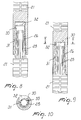
- detachable coupling means are provided, that may have the configuration shown in Figures 7 to 10, which have a frustum-shaped portion 25 that is associated with one end of the modular elements 21 and can be inserted in a frustum-shaped receptacle 26, with particular but not exclusive examples, conical that is formed both on the other end of modular elements 21 and on the coupling tang 28 that is formed in a central portion of the cross-member 10.
- a radial protrusion 30 which engages a longitudinal recess 31 formed in the conical receptacle 26, which ends at an inclined locking plane 32, where the protrusion 30 engages, by virtue of the rotation of the frustum-shaped portion 25 with respect to the frustum-shaped receptacle with simultaneous locking in an axial direction; there is also a rotation-preventing element 33.
- supporting pads 35 are advantageously provided on the active faces of the fork-like elements 12, which are preferably formed by pieces or plugs of elastic material or similar materials, such as a sponge-like material or rubber-like plastic material.
- This arrangement by having an upper portion, allows a safer coupling; moreover, the vertical portion 41 allows easier and more comfortable engagement of the fork with the rod, since during the engagement step it is sufficient to rest the rod against the vertical portion 41 in order to have a guide for the engagement between the fork 12 and the rod 3.
- Figure 13 provides an embodiment in which at the end of the arms 11, at the fork 12, there is a locking means that allows to prevent accidental disengagement of the rod from the fork 12.
- Said locking means provide for an oscillating hook 50, which is pivoted at 51 to the base of the fork so as to have an eccentric mass 52, which in the absence of other forces causes the hook to arrange itself in an open position, i.e., such as to disengage from the upper part of the fork.
- the oscillating hook 50 has a tab 53 that is arranged inside the fork and, by engaging the rod 3, turns the hook 50 into the closed position.
- the rod 3 When disengagement is performed, the rod 3 tends to move away from the fork and accordingly the hook 50, due to the presence of the eccentric mass 15, simply by gravity, returns to the open position, thus allowing quick and easy disengagement of the rod from the structure in order to fit and remove the curtains.
- a tool which has a structure that is particularly simple and lightweight and allows easily to fit and remove curtains without having to use stepladders, since the supporting structure, with the engagement of the supporting element, allows the operator to perform this operation while keeping his feet on the ground.
- Another important aspect further consists in that the tool is obtained from modular elements that are quick and easy to assemble, and therefore it has very small dimensions that allow to perform a very compact packaging, and further allows to store the tool in very small spaces when it is not being used.
- the engagement structure can be constituted by a transverse bar 60, which is connected to a supporting element, again designated by the reference numeral 20. Arms 61 extend from the bar 60 and form saddle-shaped portions 62 that are spaced from the bar 60 for engagement with the rod 3.
- the engagement structure can be constituted by a cradle-like bar 70, which accommodates the rod 3 and is provided with elastically yielding engagement elements 71 for retaining the rod 3.
Landscapes
- Ladders (AREA)
- Curtains And Furnishings For Windows Or Doors (AREA)
Applications Claiming Priority (2)
| Application Number | Priority Date | Filing Date | Title |
|---|---|---|---|
| ITMI20040343 | 2004-02-26 | ||
| ITMI20040343 ITMI20040343A1 (it) | 2004-02-26 | 2004-02-26 | Attrezzo per il montaggio e lo smontaggio di tende senza l'uso di scale |
Publications (2)
| Publication Number | Publication Date |
|---|---|
| EP1574156A2 true EP1574156A2 (de) | 2005-09-14 |
| EP1574156A3 EP1574156A3 (de) | 2006-09-06 |
Family
ID=34814956
Family Applications (1)
| Application Number | Title | Priority Date | Filing Date |
|---|---|---|---|
| EP05003888A Withdrawn EP1574156A3 (de) | 2004-02-26 | 2005-02-23 | Werkzeug zum Montieren und Abmontieren von Gardinen ohne Leitern |
Country Status (2)
| Country | Link |
|---|---|
| EP (1) | EP1574156A3 (de) |
| IT (1) | ITMI20040343A1 (de) |
Family Cites Families (5)
| Publication number | Priority date | Publication date | Assignee | Title |
|---|---|---|---|---|
| DE73196C (de) * | J. PREHN in Ratibor | Vorrichtung zum Abheben von Gardinen- und Vorhangstangen von ihren Haken | ||
| GB123025A (en) * | 1918-10-09 | 1919-02-13 | Jabez Scarlett | A Curtain Pole Lifter and Picture Hanger. |
| GB149753A (en) * | 1919-05-16 | 1920-08-16 | Joseph Chambers | A cornice pole and curtain lifter |
| US1334649A (en) * | 1919-05-23 | 1920-03-23 | Cayton Max | Curtain-pole lifter |
| FR534483A (fr) * | 1921-01-18 | 1922-03-27 | Dispositif pour enlever et remettre en place des rideaux ou des portières |
-
2004
- 2004-02-26 IT ITMI20040343 patent/ITMI20040343A1/it unknown
-
2005
- 2005-02-23 EP EP05003888A patent/EP1574156A3/de not_active Withdrawn
Also Published As
| Publication number | Publication date |
|---|---|
| ITMI20040343A1 (it) | 2004-05-26 |
| EP1574156A3 (de) | 2006-09-06 |
Similar Documents
| Publication | Publication Date | Title |
|---|---|---|
| US5297306A (en) | Multipurpose outdoor tool | |
| US7475856B2 (en) | Shackle for load supporting bracket assembly | |
| NO139249B (no) | Sammensettbart leketoey. | |
| US4004393A (en) | Adjustable heighth shoring | |
| US7246463B1 (en) | Christmas tree support assembly | |
| JP5443441B2 (ja) | 作業台 | |
| JP4895919B2 (ja) | ビニールハウスの骨材固定用楔 | |
| EP2000612B1 (de) | Gerüst mit absperrbaren Teilen | |
| WO2007081156A1 (en) | Cane with auxiliary foot | |
| JP6383401B2 (ja) | 折畳み家具 | |
| US20080135696A1 (en) | Retractable tool stand | |
| KR20190010300A (ko) | 액세서리 착탈식 복합운동기구 | |
| KR200264139Y1 (ko) | 작업용 발판 | |
| CN209760739U (zh) | 一种建筑施工用脚手架 | |
| CN220551052U (zh) | 一种新型晾衣梯 | |
| KR102863992B1 (ko) | 접이식 낫 | |
| KR200430922Y1 (ko) | 길이가 가변되는 접이식 사다리. | |
| KR20170001302U (ko) | 사다리에 탈부착되는 공구함 | |
| KR20160000108U (ko) | 사용 편리성을 향상시킨 삽 | |
| FR2581553A2 (fr) | Appareil de gymnastique | |
| JP4535996B2 (ja) | 電柱設置装置 | |
| CN212439865U (zh) | 一种扶手支架 | |
| JPH07328959A (ja) | 鋸腰下用鞘 | |
| KR200245231Y1 (ko) | 마포걸래 밀대 홀더 | |
| KR102771263B1 (ko) | 협동 갈퀴질이 가능한 작업성이 개선된 갈퀴 |
Legal Events
| Date | Code | Title | Description |
|---|---|---|---|
| PUAI | Public reference made under article 153(3) epc to a published international application that has entered the european phase |
Free format text: ORIGINAL CODE: 0009012 |
|
| AK | Designated contracting states |
Kind code of ref document: A2 Designated state(s): AT BE BG CH CY CZ DE DK EE ES FI FR GB GR HU IE IS IT LI LT LU MC NL PL PT RO SE SI SK TR |
|
| AX | Request for extension of the european patent |
Extension state: AL BA HR LV MK YU |
|
| PUAL | Search report despatched |
Free format text: ORIGINAL CODE: 0009013 |
|
| AK | Designated contracting states |
Kind code of ref document: A3 Designated state(s): AT BE BG CH CY CZ DE DK EE ES FI FR GB GR HU IE IS IT LI LT LU MC NL PL PT RO SE SI SK TR |
|
| AX | Request for extension of the european patent |
Extension state: AL BA HR LV MK YU |
|
| AKX | Designation fees paid | ||
| REG | Reference to a national code |
Ref country code: DE Ref legal event code: 8566 |
|
| STAA | Information on the status of an ep patent application or granted ep patent |
Free format text: STATUS: THE APPLICATION IS DEEMED TO BE WITHDRAWN |
|
| 18D | Application deemed to be withdrawn |
Effective date: 20070307 |