EP1573263B1 - Zwischenstück mit beweglichem dorn zum verbinden einer druckgaspatrone mit einer luftdruckwaffe für paintbullgeschosse - Google Patents
Zwischenstück mit beweglichem dorn zum verbinden einer druckgaspatrone mit einer luftdruckwaffe für paintbullgeschosse Download PDFInfo
- Publication number
- EP1573263B1 EP1573263B1 EP03790361A EP03790361A EP1573263B1 EP 1573263 B1 EP1573263 B1 EP 1573263B1 EP 03790361 A EP03790361 A EP 03790361A EP 03790361 A EP03790361 A EP 03790361A EP 1573263 B1 EP1573263 B1 EP 1573263B1
- Authority
- EP
- European Patent Office
- Prior art keywords
- adapter body
- adapter assembly
- paintball marker
- bottle
- piercing pin
- Prior art date
- Legal status (The legal status is an assumption and is not a legal conclusion. Google has not performed a legal analysis and makes no representation as to the accuracy of the status listed.)
- Expired - Lifetime
Links
- 239000003550 marker Substances 0.000 title claims abstract description 62
- 239000012530 fluid Substances 0.000 claims abstract description 8
- 238000000034 method Methods 0.000 claims description 10
- 230000033001 locomotion Effects 0.000 claims description 5
- 238000000926 separation method Methods 0.000 claims description 2
- 238000007789 sealing Methods 0.000 description 13
- 239000003380 propellant Substances 0.000 description 11
- 239000007789 gas Substances 0.000 description 7
- 230000000149 penetrating effect Effects 0.000 description 7
- CURLTUGMZLYLDI-UHFFFAOYSA-N Carbon dioxide Chemical compound O=C=O CURLTUGMZLYLDI-UHFFFAOYSA-N 0.000 description 3
- 238000013459 approach Methods 0.000 description 3
- 230000007246 mechanism Effects 0.000 description 3
- 230000035515 penetration Effects 0.000 description 3
- 229910002092 carbon dioxide Inorganic materials 0.000 description 2
- 239000001569 carbon dioxide Substances 0.000 description 2
- 238000004891 communication Methods 0.000 description 2
- 230000002708 enhancing effect Effects 0.000 description 2
- 238000010304 firing Methods 0.000 description 2
- 230000000977 initiatory effect Effects 0.000 description 2
- 238000004519 manufacturing process Methods 0.000 description 2
- 239000000463 material Substances 0.000 description 2
- 239000003973 paint Substances 0.000 description 2
- 230000015572 biosynthetic process Effects 0.000 description 1
- 230000015556 catabolic process Effects 0.000 description 1
- 230000001010 compromised effect Effects 0.000 description 1
- 238000010276 construction Methods 0.000 description 1
- 238000006731 degradation reaction Methods 0.000 description 1
- 230000000994 depressogenic effect Effects 0.000 description 1
- 230000013011 mating Effects 0.000 description 1
- 230000002093 peripheral effect Effects 0.000 description 1
- 230000001141 propulsive effect Effects 0.000 description 1
- 230000000717 retained effect Effects 0.000 description 1
- 238000004513 sizing Methods 0.000 description 1
- 238000013022 venting Methods 0.000 description 1
Images
Classifications
-
- F—MECHANICAL ENGINEERING; LIGHTING; HEATING; WEAPONS; BLASTING
- F41—WEAPONS
- F41B—WEAPONS FOR PROJECTING MISSILES WITHOUT USE OF EXPLOSIVE OR COMBUSTIBLE PROPELLANT CHARGE; WEAPONS NOT OTHERWISE PROVIDED FOR
- F41B11/00—Compressed-gas guns, e.g. air guns; Steam guns
- F41B11/60—Compressed-gas guns, e.g. air guns; Steam guns characterised by the supply of compressed gas
- F41B11/62—Compressed-gas guns, e.g. air guns; Steam guns characterised by the supply of compressed gas with pressure supplied by a gas cartridge
-
- Y—GENERAL TAGGING OF NEW TECHNOLOGICAL DEVELOPMENTS; GENERAL TAGGING OF CROSS-SECTIONAL TECHNOLOGIES SPANNING OVER SEVERAL SECTIONS OF THE IPC; TECHNICAL SUBJECTS COVERED BY FORMER USPC CROSS-REFERENCE ART COLLECTIONS [XRACs] AND DIGESTS
- Y10—TECHNICAL SUBJECTS COVERED BY FORMER USPC
- Y10T—TECHNICAL SUBJECTS COVERED BY FORMER US CLASSIFICATION
- Y10T137/00—Fluid handling
- Y10T137/1624—Destructible or deformable element controlled
- Y10T137/1632—Destructible element
- Y10T137/1692—Rupture disc
- Y10T137/1759—Knife or cutter causes disc to break
- Y10T137/1767—Movable knife or cutter
Definitions
- the present invention relates to a paintball marker, and more particularly to an adapter assembly for operably connecting a pressurized propellant source to the marker.
- US 6,314,954 (which forms a basis for the preamble of claims 1 and 7) discloses a toy gun for firing paint bullets comprising a mini-gas container disposed in a chamber of the casing of the gun.
- a stinger pierces into the sealed air outlet of the container through a small control bore of a bushing.
- a tubular shaft seat is fasted to a sleeve and has a large central bore communicating with the small control bore.
- a hollow shaft inserted into the shaft seat is biased by a spring.
- Paintball markers employ compressed gas to provide the motive force (propellant) for the paintballs.
- the compressed gas is retained in a pressurized container, wherein the size of the container generally determines amount compressed gas available for projecting the paintballs.
- paintball marker user must balance the larger capacity of rechargeable, large volume tanks with their relative bulk and weight against smaller, lighter disposable tanks having less capacity.
- a need exists for an assembly for enhancing the operable interconnection of a pressurized bottle with a paintball marker.
- a need further exists for a method by which disposable pressurized bottles can be selectively and releasably engaged with a paintball marker.
- the present invention provides an adapter assembly for interconnecting a pressurized bottle with a paintball marker, wherein pressurized fluid within the bottle is not exposed to the marker until the adapter assembly is engaged with both the paintball marker and the bottle. That is, the adapter assembly is directed to reducing venting of the pressurized bottle, unless the bottle is engaged with the adapter assembly and the adapter assembly is engaged with the paintball marker.
- the adapter assembly can cooperatively engage a disposable pressurized bottle, and fluidly connect the bottle to a paintball marker prior to puncturing (opening) the bottle.
- a configuration of the adapter assembly includes an adapter body having a female socket for receiving a portion of the pressurized bottle, a male head for engaging the paintball marker and a passage through the head, and a piercing pin movably connected to the adapter body between a retracted position and an extended position.
- the female socket can include means for releasably engaging the pressurized bottle and the male head can include means for releasably engaging the paintball marker.
- the female socket of the adapter body is internally threaded and the male head is externally threaded.
- the adapter assembly also provides the piercing pin is movably disposed within a portion of the passage.
- the female socket and the male head form a sealed interface with a corresponding surface of the bottle and the paintball marker, respectively.
- One configuration of the adapter assembly provides for releasably engaging an adapter body having a movable piercing pin with a pressurized bottle, and subsequently releasably engaging the adapter body with the paintball marker so that the piercing pin then punctures the pressurized bottle. That is, in its intended use, the adapter body cooperatively engages the pressurized bottle without puncturing the bottle and the coupled bottle and adapter body are then engaged with the paintball marker such that the piercing pin of the adapter body punctures the pressurized bottle after the adapter assembly is cooperatively engaged by the marker and a sealed interface has been created.
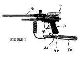
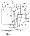
- a paintball marker 10 is shown operably interconnected to a pressurized bottle 30 by an adapter assembly 40.
- the paintball marker 10 generally includes a grip 12, a hopper for retaining a plurality of paintballs to be discharged, a barrel 16 and a trigger 18.
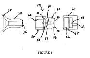
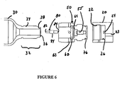
- the paintball marker 10, as seen in Figures 3 , 4 , and 6 includes female connector 20 for engaging an external propellant source.
- the female connector 20 preferably includes internal threads 22.
- a duct 23 extends from the female connector 20 to a firing mechanism of the paintball marker 10.
- an actuating stand off 24 projects from an inner end of the female connector 20.
- the stand off 24 is located to align with a predetermined portion of the adapter assembly 40 upon operably engagement of the adapter assembly with the female connector 20.
- the female connector 20 includes a transverse vent 25.
- the female connector 20 further includes a sealing portion 26 for contacting a portion of the adapter assembly 40 to form a sealed interface therebetween.
- the female connector 20 of the paintball marker 10 is shown adjacent the grip 12, it is understood the female connector can be located at any of a variety of locations relative to the paintball marker. That is, the female connector 20 can be attached to any available portion of the marker in either a permanent or releasable connection.
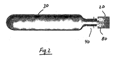
- the pressurized bottle 30 is constructed to retain a propellant such as a compressed gas or a combination of gases. While the pressurized bottle 30 can be any of a variety of sizes, various governmental rules and regulations apply to various modes of transport of certain bottle configurations. Thus, the particular size, weight, capacity and configuration of the bottle is often, at least partially dictated by these regulations.
- the pressurized bottle 30 can be referred to as a container, tank or vessel and can be disposable, single use, rechargeable or refillable.
- the pressurized bottle 30 is set forth as a disposable bottle retaining an initial amount of pressurized propellant.
- the pressurized bottle 30 in relevant part, includes a male connector 32 having an external threaded surface 34 and a frangible , or pierceable seal 36 located on an annular seat 38.
- the pierceable seal 36 and the attachment of the seal to the annular seat 38 are known in the art. That is, the seal 36 can be limited to an overlying seal, or can be incorporated into a cap structure.
- the pressurized bottle 30 further includes a seating surface 35.
- the seating surface 35 is generally frustoconical, but can be any of a variety of shapes that can cooperate with a corresponding portion of the adapter assembly 40.
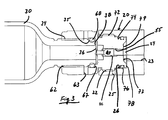
- the adapter assembly 40 includes an adapter body 50 and a piercing pin 80 moveably connected to the adapter body between an extended position and a retracted position.
- the adapter body 50 includes a female socket 60 for engaging the pressurized bottle 30 and a male head 70 for engaging the paintball marker 10.
- the female socket 60 includes internal threads 62 and the male head includes external threads 72.
- a passage 55 extends from the female socket 60 and through the male head 70.
- the female socket 60 includes a positive stop 64 for limiting penetration of the bottle 30 into the socket.
- the positive stop 64 can have any of a variety of configurations, but is shown as an internal shoulder.
- the female socket 60 also includes an annular groove 67 longitudinally intermediate the positive stop 64 and the open end of the female socket 60. It is understood the longitudinal direction extends along the axis of the adapter body, and is coincident with the axis about which the body rotates during threaded engagement with the pressurized bottle 30 or the female connector 20.
- An O-ring 68 is disposed in the groove 67 for forming a sealing interface with the sealing section 35 of the pressurized bottle 30.
- the female socket 60 of the adapter assembly 40 includes at least one, and preferably a plurality, such as four or more radial vents 63. As seen in Figures 3 , 4 and 5 , the radial vents are longitudinally intermediate the O-ring 68 and the open end of the female socket 60.
- the male head 70 defines an outer surface having the threads 72 and a sealing section 74, wherein the threads are intermediate the sealing section and the female socket 60.
- the sealing section 74 includes a peripheral groove 75 into which a seal 76, such as an O-ring, is disposed.
- a terminal end of the male head 70 includes a recess 77, such that the passage 55 terminates in the recess.
- the recess 77 is sized to provide fluid communication from the passage 55 to the duct 23 in the paintball marker 10 upon any rotational orientation of the adapter assembly 40.
- the recess 77 is at least partially defined by an annular ridge 78, thereby defining a central floor 79.
- the piercing pin 80 is disposed within the passage 55 and moveable between an extended position and a retracted position.
- the passage 55 and the piercing pin 80 are sized to provide a generally annular flow path therebetween.
- An end of the piercing pin projecting into the female socket 60 is configured as a penetrating surface 82 for selectively contacting and piercing the frangible seal 36 of the pressurized bottle 30.
- the penetrating surface 82 can be faceted or angled for enhancing puncturing of the frangible seal 36 on the pressurized bottle 30.
- the piercing pin 80 has a driven end 84 for contacting the stand off 24.
- the piercing pin 80 can be moveably coupled to the adapter body 50 by any of a variety of mechanisms. Grooves, slides or guide ribs can be used to define the travel of the piercing pin 80 relative to the adapter body 50. As seen in Figures 3-5 , the piercing pin 80 includes a longitudinally extending bulbous portion 86.
- the passage 55 in the adapter body 50 includes a pair of spaced shoulders 52A and 52B to capture the bulbous portion 86 therebetween. The distance between the shoulders 52A and 52B and the sizing of the bulbous portion 86 dictate the range of motion of the piercing pin 80 between the retracted position and the extended position.
- the components are selected to locate the driven end 84 of the piercing pin 80 in the retracted position substantially flush with an adjacent portion of the central floor 79 of the male head 70. In this configuration, the driven end 84 is depressed from the central floor 79 upon the piercing pin 80 being disposed in the extended position.
- the shoulders 52A and 52B can be formed in any of a variety of configurations.
- one of the shoulders 52A can be formed from a flange or flanges 54 that are deformed or bent into operable position.
- the adapter body 50 includes an annular deformable flange 54 at the terminal end of the passage 55 in the female socket 60.
- the flanges 54 are formed in an open position allowing the piercing pin 80 to be disposed within the passage 55.
- the flange 54 is then bent to form the shoulder 52A for limiting travel of the piercing pin 80 into the female socket 60.
- the shoulder 52B can be integrally formed in the adapter body 50.
- the adapter assembly 40 can comply with an industry standard, such as ASTM F 1750 - 96, Standard Specification for Paintball Gun Threaded-Propellant Source Interface, herein incorporated by reference.
- ASTM F 1750 - 96 Standard Specification for Paintball Gun Threaded-Propellant Source Interface
- ASTM F 1750 - 96 Standard Specification for Paintball Gun Threaded-Propellant Source Interface
- the Standard dictates male and female threaded connectors for interfacing a propellant source and a paintball gun (marker).
- the standard requires the female connector is configured as part of the paintball gun and the male connector is configured as part of the propellant source.
- the male and female connectors are made form materials compatible with carbon dioxide (CO 2 ).
- CO 2 carbon dioxide
- the adapter assembly 40 is initially engaged with the female connector 20 of the paintball marker 10, and the pressurized bottle 30 is then engaged with the adapter assembly.
- the external threads 72 of the male head 70 are cooperatively engaged with the corresponding internal threads 22 of the female connector 20.
- a sealed interface is formed between the O-ring seal 76 of the male head sealing section 74 and the sealing portion 26 of the female connector 20.
- the stand off 24 is aligned with the passage 55 and hence the piercing pin 80.
- the stand off 24 contacts the driven end 84 of the piercing pin 80, thereby initiating movement of the piercing pin toward the extended position.
- the stand off 24 contacts the piercing pin 80 and disposes the piercing pin in the extended position.
- the internal threads 62 of the female socket 60 in the adapter assembly 40 are threadedly engaged with the corresponding threaded external surface 34 of the pressurized bottle 30.
- the O-ring seal 68 contacts the seating surface 35 of the pressurized bottle 30 and forms a sealed interface therebetween.
- the adapter assembly 40 can be initially engaged with the pressurized bottle 30, and the adapter assembly then engaged with the female connector 20 of the paintball marker 10.
- the internal threads 62 of the female socket 60 in the adapter assembly 40 are threadedly engaged with the corresponding threaded external surface 34 of the pressurized bottle 30.
- Continued threaded engagement causes the O-ring 68 to contact the seating surface 35 of the pressurized bottle 30 and formation of a sealed interface therebetween.
- the sealed interface is formed between the seating surface 35 and the O-ring 68
- further threaded engagement continues until the pressurized bottle 30 contacts the positive stop 64.
- the piercing pin 80 may contact the pierceable seal 36.
- the piercing pin 80 travels toward the male head 70 of the adapter body 50 and does not puncture the seal 36.
- the driven end 84 is substantially flush with the adjacent portion of the central floor 79, and is thereby partially protected by the annular ridge 78 from unintentional contact which could urge the pin toward the extended position, and possible penetration of the seal 36. Movement of the piercing pin 80 toward the retracted position prevents the pin from puncturing the seal 36.
- the pressurized bottle 30 is thus fully engaged with the adapter assembly 40, thereby fluidly connecting the passage 55 and the seal 36, and the piercing pin 80 is moved to the retracted position and does not puncture or penetrate the seal of the bottle.
- the coupled adapter assembly 40 and pressurized bottle 30 are then engaged with the paintball marker 10.
- the external threads 72 of the male head 70 engage the internal thread 22 of the female connector 20 of the paintball marker 10.
- a sealed interface is formed between the O-ring 76 of the male head sealing section 74 and the sealing portion 26 of the female connector 20.
- the stand off 24 is aligned with the passage 55 and hence the piercing pin 80.
- the stand off 24 contacts the driven end 84 of the piercing pin 80, thereby initiating movement of the piercing pin from the retracted position toward the extended position.
- the penetrating surface 82 of the piercing pin 80 contacts the pierceable seal 36 of the pressurized bottle 30.
- the O-ring 68 in the female socket 60 has formed a sealed interface with the seating surface 35 of the pressurized bottle 30.
- the sealing section 74 of the male head 70 and the sealing portion 26 of the female connector 20 have formed a sealed interface.
- fluid communication is provided from the duct 23 to the pierceable seal 36.
- both the bottle 30 and the paintball marker 10 will bleed or vent to ambient pressure. Specifically, as the bottle 30 is unthreaded from the adapter assembly 40, any remaining pressure in the bottle will vent through vents 63 in the adapter body 50. Pressure from the paintball marker 10, expressed in the duct 23, will urge the piercing pin 80 to the fully extended position. In the fully extended position, the bulbous portion 86 contacts the shoulder 52A in the female socket 60. Contact of the bulbous portion 86 with the shoulder 52A does not form a sealed interface precluding fluid flow through the passage 55.
- the shoulder 52A is formed to preclude a sealed interface between the shoulder and the piercing pin 80. That is, less than the entire flange 54 can be deformed to form the shoulder 52A. Those portions of the flange 54 that are not formed into the shoulder 52A are thus spaced from bulbous portion 86 and provide a flow path therebetween.
- the flow path through the passage 55 can also be provided by any of a variety of structures including a longitudinally extending groove or channel 87 in the bulbous portion 86.
- the piercing pin 80 can be a hollow member having a central passageway therethrough.
- the paintball marker will vent to ambient pressure, and the bottle may bleed to ambient pressure or remain substantially sealed to the adapter assembly.
- pressure in the duct 23 will vent to ambient pressure through the vent 25 in the female connector 20.
- Pressure remaining in the bottle 30 will urge the piercing pin 80 to the fully retracted position, such that the bulbous portion 86 contacts the shoulder 52B.
- the interface between piercing pin 80 in the retracted position and adapter body 50 can be constructed to provide either a relatively slow bleed of the pressure in the bottle 30 along the interface, or a substantially sealed interface. In the bleed configuration, the interface allows pressure to bleed without creating a significant propulsive force on the bottle. In the relatively sealed interface, the coupled adapter assembly 40 and bottle 30 could be removed from a first paintball marker and engaged with a second paintball marker, without significant loss of propellant.
- the interface between the piercing pin 80 in the retracted position and the adapter body 50 can include at least one groove or channel to provide the bleed, or be mating surfaces substantially forming a seal therebetween.
- adapter assembly 40 has been described in terms of male and female threaded interfaces, it is contemplated any of a variety of releasable mechanisms such as bayonet, detent snap, rings or even friction fits can be employed. Alternatively, or additionally clamps or external retainers can be employed.
- the adapter assembly 40 thus provides that the frangible seal 36 of the pressurized bottle 30 is not compromised (punctured) until the adapter assembly 40 is sufficiently engaged with the paintball marker 10 to preclude unintended separation of the bottle from the adapter assembly (and hence paintball marker 10). Therefore, upon puncturing the pierceable seal 36, the adapter assembly 40 is sufficiently engaged with both the bottle 30 and the paintball marker 10 to reduce occurrence of uncontrolled puncturing of the pressurized bottle.
- the length of travel of the piercing pin 80 (between the retracted position and the extended position) and the sealing interface formed between the male head 70 and the female connector 20. That is, the male head 70 and the female connector 20 define a sealed interface of sufficient longitudinal distance to allow the piercing pin 80 to travel a sufficient distance to puncture the pierceable seal 36.
- the adapter assembly 40 upon the adapter assembly 40 being operably engaged with the female connector 20 (thereby disposing the piercing pin 80 in the extended position), the adapter assembly is configured to form a sealed interface with the seating surface 35 of the pressurized bottle 30 prior to the piercing pin penetrating the seal 36 and exposing the adapter assembly to the pressurized propellant.
Landscapes
- Engineering & Computer Science (AREA)
- General Engineering & Computer Science (AREA)
- Containers And Packaging Bodies Having A Special Means To Remove Contents (AREA)
- Filling Or Discharging Of Gas Storage Vessels (AREA)
- Catching Or Destruction (AREA)
- Coating Apparatus (AREA)
Claims (12)
- Adapteranordnung (40) für eine Fluidverbindung einer Druckflasche (30), die ein außen mit einem Gewinde versehendes männliches Anschlussstück (70) aufweist, mit einem Paintball-Markierer (10), der ein innen mit einem Gewinde versehenes weibliches Anschlussstück (20) aufweist, wobei die Adapteranordnung (40) Folgendes umfasst:einen Adapterkörper (50), der einen innen mit einem Gewinde versehenen Sockel (60), einen außen mit einem Gewinde versehenen Kopf (70) und einen Durchgang (55) durch den Kopf (70) aufweist, undeinen Durchstoßdorn (80), der mit dem Adapterkörper (50) zwischen einer eingezogenen Position und einer ausgefahrenen Position bewegbar verbunden ist,dadurch gekennzeichnet, dass der Sockel (60) einen festen Anschlag (64), eine O-Ring-Dichtung (68) und eine Entgasungsöffnung (63) umfasst, wobei sich die O-Ring-Dichtung (68) längs zwischen dem festen Anschlag (64) und der Entgasungsöffnung (63) befindet.
- Adapteranordnung nach Anspruch 1, dadurch gekennzeichnet, dass der Durchstoßdorn (80) innerhalb eines Abschnitts des Durchgangs (55) angeordnet ist.
- Adapteranordnung nach Anspruch 1, dadurch gekennzeichnet, dass der Durchstoßdorn (80) ein angetriebenes Ende umfasst, wobei das angetriebene Ende in der eingezogenen Position im Wesentlichen eben mit einem benachbarten Abschnitt des Adapterkörpers (50) ist.
- Adapteranordnung nach Anspruch 1, dadurch gekennzeichnet, dass der Adapterkörper (50) ein Paar von beabstandeten Absätzen aufweist, die so ausgewählt werden, dass sie die Bewegung des Durchstoßdorns (80) zwischen der eingezogenen Position und der ausgefahrenen Position beschränken.
- Adapteranordnung nach Anspruch 1, dadurch gekennzeichnet, dass wenigstens ein Teil des Durchstoßdorns (80) innerhalb des Durchgangs (55) angeordnet ist, um einen Durchflussweg dazwischen zu bilden.
- Adapteranordnung nach Anspruch 1, dadurch gekennzeichnet, dass der Adapterkörper (50) und der Durchstoßdorn (80) so ausgewählt werden, dass der Durchstoßdorn (80) in der ausgefahrenen Position nur dann angeordnet wird, wenn der Adapterkörper (50) mit dem Paintball-Markierer (10) in Eingriff gebracht wird.
- Verfahren zum Exponieren eines Paintball-Markierers (10) einer Druckflasche (30), die ein Druckfluid hält, wobei das Verfahren die folgenden Schritte umfasst:lösbares Ineingriffbringen eines Adapterkörpers (50) mit der Druckflasche (30), undlösbares Ineingriffbringen des Adapterkörpers (50) mit dem Paintball-Markierer (10),wobei der Adapterkörper (50) einen innen mit einem Gewinde versehenen Sockel (60), einen außen mit einem Gewinde versehenen Kopf (70) und einen Durchgang (55) durch den Kopf aufweist,
Durchstechen der in Eingriff gebrachten Flasche mit einem Durchstoßdorn (80), der zwischen einer ausgefahrenen Position und einer eingezogenen Position bewegbar ist, um das Druckfluid mit dem Paintball-Markierer (10) durch den Adapterkörper (50) fließend zu verbinden, dadurch gekennzeichnet, dass
der Sockel (60) einen festen Anschlag (64), eine O-Ring-Dichtung (68) und eine Entgasungsöffnung (63) umfasst, und
dass die O-Ring-Dichtung (68) längs zwischen dem festen Anschlag (64) und der Entgasungsöffnung (63) positioniert ist. - Verfahren nach Anspruch 7, dadurch gekennzeichnet, dass das lösbare Ineingriffbringen des Adapterkörpers (50) mit der Druckflasche (30) das Bilden einer abgedichteten Schnittstelle zwischen dem Adapterkörper (50) und der Druckflasche (30) umfasst.
- Verfahren nach Anspruch 7, dadurch gekennzeichnet, dass das lösbare Ineingriffbringen des Adapterkörpers (50) mit der Druckflasche (30) das Ineingriffbringen des Adapterkörpers (50) in der Druckflasche (30) durch Verschrauben umfasst.
- Verfahren nach Anspruch 7, dadurch gekennzeichnet, dass das lösbare Ineingriffbringen des Adapterkörpers (50) mit dem Paintball-Markierer (10) das Bilden einer abgedichteten Schnittstelle zwischen dem Adapterkörper (50) und dem Paintball-Markierer (10) umfasst.
- Verfahren nach Anspruch 7, dadurch gekennzeichnet, dass das lösbare Ineingriffbringen des Adapterkörpers (50) mit dem Paintball-Markierer (10) das Ineingriffbringen des Adapterkörpers (50) mit dem Paintball-Markierer (10) durch Verschrauben umfasst.
- Verfahren nach Anspruch 7, gekennzeichnet durch das Ineingriffbringen der Druckflasche (30) mit dem Adapterkörper (50), um eine unbeabsichtigte Trennung vor dem Durchstechen der Druckflasche (30) zu vermeiden.
Applications Claiming Priority (3)
| Application Number | Priority Date | Filing Date | Title |
|---|---|---|---|
| US315596 | 2002-12-10 | ||
| US10/315,596 US6941938B2 (en) | 2002-12-10 | 2002-12-10 | Adapter assembly with floating pin for operably connecting pressurized bottle to a paintball marker |
| PCT/US2003/038675 WO2004053419A1 (en) | 2002-12-10 | 2003-12-05 | Adapter assembly with floating pin for operably connecting pressurized bottle to a paintball marker |
Publications (2)
| Publication Number | Publication Date |
|---|---|
| EP1573263A1 EP1573263A1 (de) | 2005-09-14 |
| EP1573263B1 true EP1573263B1 (de) | 2008-07-09 |
Family
ID=32468744
Family Applications (1)
| Application Number | Title | Priority Date | Filing Date |
|---|---|---|---|
| EP03790361A Expired - Lifetime EP1573263B1 (de) | 2002-12-10 | 2003-12-05 | Zwischenstück mit beweglichem dorn zum verbinden einer druckgaspatrone mit einer luftdruckwaffe für paintbullgeschosse |
Country Status (7)
| Country | Link |
|---|---|
| US (1) | US6941938B2 (de) |
| EP (1) | EP1573263B1 (de) |
| AT (1) | ATE400788T1 (de) |
| AU (1) | AU2003293414A1 (de) |
| DE (1) | DE60322107D1 (de) |
| ES (1) | ES2310683T3 (de) |
| WO (1) | WO2004053419A1 (de) |
Families Citing this family (19)
| Publication number | Priority date | Publication date | Assignee | Title |
|---|---|---|---|---|
| US7107981B1 (en) * | 2003-06-11 | 2006-09-19 | Jason Forrest Dunn | Device for securing a compressed gas system to a paintball gun |
| US20050284525A1 (en) * | 2004-06-25 | 2005-12-29 | Schnell Richard E | Manually-operated piloted control-reliable lockout valve |
| US7178516B2 (en) * | 2004-07-08 | 2007-02-20 | Dale Carpenter | Methods and apparatus for an in-line direct connect air source adapter |
| US20060076001A1 (en) * | 2004-10-12 | 2006-04-13 | Haisley Gregory K | Adjustable anti-siphon pin valve for paintball gun |
| US7258138B2 (en) * | 2005-01-11 | 2007-08-21 | Dale Carpenter | Methods and apparatus for an on-off controller |
| US7210499B2 (en) * | 2005-01-18 | 2007-05-01 | Dale Carpenter | Methods and apparatus for a direct connect on-off controller |
| US20100031943A1 (en) * | 2008-08-08 | 2010-02-11 | K&L Air Products Inc. | Coupler Assembly for Dispensing Fluid from a Compressed Fluid Source |
| WO2010132543A1 (en) * | 2009-05-14 | 2010-11-18 | Sturm Ruger & Company, Inc. | Bolt carrier for gas operated rifle |
| US8322329B1 (en) | 2010-01-06 | 2012-12-04 | Long Range, Llc | Systems, devices, and/or methods for launching a projectile |
| GB201006363D0 (en) * | 2010-04-16 | 2010-06-02 | Linde Ag | Gas supply system |
| EP3102869B1 (de) * | 2014-02-04 | 2020-01-01 | Strauss Water Ltd | Druckgasbehälter und kupplungsmittel für anwendungen |
| EP3037712A1 (de) * | 2014-12-23 | 2016-06-29 | Linde Aktiengesellschaft | Sicherheits-Abdichtungsverbindung für einen Gaszylinder |
| WO2016135715A1 (en) * | 2015-02-25 | 2016-09-01 | Strauss Water Ltd. | Pressurized gas container |
| US9593905B2 (en) * | 2015-04-21 | 2017-03-14 | Jui-Fu Tseng | Pull ring for air container of airsoft gun |
| US20180164069A1 (en) * | 2016-12-09 | 2018-06-14 | Kien Well Toy Industrial Co., Ltd. | Toy gun magazine module |
| US10378697B2 (en) * | 2017-03-22 | 2019-08-13 | Hybrid Research Company Limited | Portable carbon dioxide adapter system |
| CN108626567B (zh) * | 2017-03-22 | 2020-05-08 | 混合研究有限公司 | 便携式二氧化碳适配器系统 |
| US12135092B2 (en) * | 2020-10-28 | 2024-11-05 | Aerojet Rocketdyne, Inc. | Fuel-isolation system having rupture diaphragm |
| DE102021212342B3 (de) | 2021-11-02 | 2022-11-24 | Andreas Jahn | Druckbehälter mit mehreren seitlichen Ausströmöffnungen |
Citations (1)
| Publication number | Priority date | Publication date | Assignee | Title |
|---|---|---|---|---|
| US20010050076A1 (en) * | 2000-03-09 | 2001-12-13 | Colby Daniel H. | Single stage regulator and method for regulating compressed air therefor |
Family Cites Families (21)
| Publication number | Priority date | Publication date | Assignee | Title |
|---|---|---|---|---|
| US1782020A (en) * | 1929-01-30 | 1930-11-18 | C O Two Fire Equipment Co | Head for puncturing closure disks |
| US2047049A (en) * | 1935-10-30 | 1936-07-07 | C O Two Fire Equipment Co | Means for discharging fluid pressure containers |
| DE1114121B (de) * | 1957-07-29 | 1961-09-21 | Richard Myer Kline | Druckgas-Handschusswaffe |
| US3059814A (en) * | 1959-11-09 | 1962-10-23 | Eugene E Poncel | Actuator for emergency water equipment |
| US3938704A (en) * | 1974-05-23 | 1976-02-17 | Offshore Devices, Inc. | Inflation control valves |
| DE2730125A1 (de) * | 1977-07-04 | 1979-01-25 | Johann Hajek | Gasdruckwaffe, insbesondere gasdruckgewehr |
| US4526730A (en) | 1983-01-31 | 1985-07-02 | Cochran Daniel M | Home carbonating apparatus |
| AT391944B (de) * | 1986-10-01 | 1990-12-27 | Steyr Daimler Puch Ag | Handschusswaffe mit fluessiggas als treibmittel fuer das geschoss |
| US4844123A (en) | 1988-09-06 | 1989-07-04 | Western/Scott Fetzer Company | Quick-connect cylinder valve and connector |
| US4959034A (en) * | 1988-10-25 | 1990-09-25 | Wass Lloyd G | Puncture disc inflation valve with improved cutting bayonet |
| US5076468A (en) * | 1990-02-28 | 1991-12-31 | Halkey-Roberts Corporation | Squib inflator adaptor |
| US5161738A (en) * | 1991-05-30 | 1992-11-10 | Wass Lloyd G | Pressure and temperature relief valve with thermal trigger |
| CH685878A5 (de) * | 1993-12-08 | 1995-10-31 | Brugg Ag Kabelwerke | Verfahren zur Herstellung eines additivbeladenen poroesen Traegermaterials |
| US5647390A (en) * | 1995-03-28 | 1997-07-15 | Wass; Lloyd G. | Thermal relief valve with improved bayonet |
| EP0805302A1 (de) * | 1996-05-03 | 1997-11-05 | WALTER TOSTO SERBATOI S.p.A. | Verteiler für aus mehreren Flüssiggaspatronen stammendes Brenngas |
| US5706795A (en) * | 1996-07-19 | 1998-01-13 | Gerwig; Phillip L. | Multi-purpose projectile launcher |
| US6260570B1 (en) * | 1997-06-16 | 2001-07-17 | Lloyd G. Wass | Puncture disc raft inflation valve having a one-piece valve body |
| US6036054A (en) | 1998-05-22 | 2000-03-14 | Sturman Bg, Llc | Attachment adapted for a carbonated liquid container |
| US6260571B1 (en) * | 1998-12-14 | 2001-07-17 | Survival Engineering, Inc. | Inflation valve assembly for liferafts |
| US6314954B1 (en) * | 2000-05-13 | 2001-11-13 | Chu-Tou Wang | Toy gun for firing paint bullets |
| US20020129806A1 (en) * | 2001-03-13 | 2002-09-19 | Kim Hak-Ryang | Ribbon discharger where gas cartrige and charged gas are interchangeable |
-
2002
- 2002-12-10 US US10/315,596 patent/US6941938B2/en not_active Expired - Fee Related
-
2003
- 2003-12-05 EP EP03790361A patent/EP1573263B1/de not_active Expired - Lifetime
- 2003-12-05 AU AU2003293414A patent/AU2003293414A1/en not_active Abandoned
- 2003-12-05 AT AT03790361T patent/ATE400788T1/de not_active IP Right Cessation
- 2003-12-05 DE DE60322107T patent/DE60322107D1/de not_active Expired - Lifetime
- 2003-12-05 WO PCT/US2003/038675 patent/WO2004053419A1/en not_active Ceased
- 2003-12-05 ES ES03790361T patent/ES2310683T3/es not_active Expired - Lifetime
Patent Citations (1)
| Publication number | Priority date | Publication date | Assignee | Title |
|---|---|---|---|---|
| US20010050076A1 (en) * | 2000-03-09 | 2001-12-13 | Colby Daniel H. | Single stage regulator and method for regulating compressed air therefor |
Also Published As
| Publication number | Publication date |
|---|---|
| WO2004053419A1 (en) | 2004-06-24 |
| DE60322107D1 (de) | 2008-08-21 |
| US6941938B2 (en) | 2005-09-13 |
| US20040107951A1 (en) | 2004-06-10 |
| EP1573263A1 (de) | 2005-09-14 |
| ES2310683T3 (es) | 2009-01-16 |
| ATE400788T1 (de) | 2008-07-15 |
| AU2003293414A1 (en) | 2004-06-30 |
Similar Documents
| Publication | Publication Date | Title |
|---|---|---|
| EP1573263B1 (de) | Zwischenstück mit beweglichem dorn zum verbinden einer druckgaspatrone mit einer luftdruckwaffe für paintbullgeschosse | |
| US6613011B2 (en) | Gas-pressured engine with valve | |
| US8171950B2 (en) | Compressed air regulator apparatus situated in canister and method for regulating compressed air thereof | |
| US7748407B2 (en) | Compressed air regulator apparatus situated in canister and method for regulating compressed air thereof | |
| US4441629A (en) | Compressed gas powered caulking gun | |
| US20110120437A1 (en) | Non-lethal pistol | |
| US9517976B2 (en) | Inflator | |
| US7921838B2 (en) | Combination non-lethal projectile launcher and flash light | |
| US11602830B2 (en) | Combustion-powered tool with sleeve-retaining lockout device | |
| US6260570B1 (en) | Puncture disc raft inflation valve having a one-piece valve body | |
| CN1037764A (zh) | 压力密封插塞式连接器 | |
| US20150168115A1 (en) | Line delivery apparatus | |
| US20240418475A1 (en) | Pressurized gas vessel and piercing mechanism | |
| US7401761B2 (en) | Compressed gas cylinder safety device | |
| CN211810148U (zh) | 一种多功能气动抛投器 | |
| EP4202286A1 (de) | Freigabeventil | |
| US20040256008A1 (en) | Build-in pneumatic reducing valve for a gas-operated gun | |
| US12474138B2 (en) | Spring-loaded piercing mechanism for a pressurized gas vessel | |
| EP4653751A1 (de) | Druckgasbehälter und durchstechmechanismus | |
| US20200378716A1 (en) | Non-provisional patent application for a projectile | |
| WO2000076588A1 (fr) | Lance-cable pneumatique portable | |
| CN107013720B (zh) | 一种联合锁机构及具有其的飞机 | |
| CN215000945U (zh) | 一种用于气囊充气的浮阀充气枪 | |
| RU2762185C1 (ru) | Конус системы заправки топливом в полете | |
| US6851381B1 (en) | Airborne mine neutralization system, neutralizer pressure relief valve |
Legal Events
| Date | Code | Title | Description |
|---|---|---|---|
| PUAI | Public reference made under article 153(3) epc to a published international application that has entered the european phase |
Free format text: ORIGINAL CODE: 0009012 |
|
| 17P | Request for examination filed |
Effective date: 20050706 |
|
| AK | Designated contracting states |
Kind code of ref document: A1 Designated state(s): AT BE BG CH CY CZ DE DK EE ES FI FR GB GR HU IE IT LI LU MC NL PT RO SE SI SK TR |
|
| AX | Request for extension of the european patent |
Extension state: AL LT LV MK |
|
| DAX | Request for extension of the european patent (deleted) | ||
| 17Q | First examination report despatched |
Effective date: 20061212 |
|
| RIN1 | Information on inventor provided before grant (corrected) |
Inventor name: WILKINSON, TODD, D. Inventor name: SCHULTZ, EDWARD, G., JR. Inventor name: D'ARCY, KENNETH, R. |
|
| GRAP | Despatch of communication of intention to grant a patent |
Free format text: ORIGINAL CODE: EPIDOSNIGR1 |
|
| GRAS | Grant fee paid |
Free format text: ORIGINAL CODE: EPIDOSNIGR3 |
|
| GRAA | (expected) grant |
Free format text: ORIGINAL CODE: 0009210 |
|
| AK | Designated contracting states |
Kind code of ref document: B1 Designated state(s): AT BE BG CH CY CZ DE DK EE ES FI FR GB GR HU IE IT LI LU MC NL PT RO SE SI SK TR |
|
| REG | Reference to a national code |
Ref country code: GB Ref legal event code: FG4D |
|
| REG | Reference to a national code |
Ref country code: CH Ref legal event code: EP |
|
| REF | Corresponds to: |
Ref document number: 60322107 Country of ref document: DE Date of ref document: 20080821 Kind code of ref document: P |
|
| REG | Reference to a national code |
Ref country code: IE Ref legal event code: FG4D |
|
| NLV1 | Nl: lapsed or annulled due to failure to fulfill the requirements of art. 29p and 29m of the patents act | ||
| REG | Reference to a national code |
Ref country code: ES Ref legal event code: FG2A Ref document number: 2310683 Country of ref document: ES Kind code of ref document: T3 |
|
| PG25 | Lapsed in a contracting state [announced via postgrant information from national office to epo] |
Ref country code: NL Free format text: LAPSE BECAUSE OF FAILURE TO SUBMIT A TRANSLATION OF THE DESCRIPTION OR TO PAY THE FEE WITHIN THE PRESCRIBED TIME-LIMIT Effective date: 20080709 Ref country code: PT Free format text: LAPSE BECAUSE OF FAILURE TO SUBMIT A TRANSLATION OF THE DESCRIPTION OR TO PAY THE FEE WITHIN THE PRESCRIBED TIME-LIMIT Effective date: 20081209 |
|
| PG25 | Lapsed in a contracting state [announced via postgrant information from national office to epo] |
Ref country code: BG Free format text: LAPSE BECAUSE OF FAILURE TO SUBMIT A TRANSLATION OF THE DESCRIPTION OR TO PAY THE FEE WITHIN THE PRESCRIBED TIME-LIMIT Effective date: 20081009 Ref country code: FI Free format text: LAPSE BECAUSE OF FAILURE TO SUBMIT A TRANSLATION OF THE DESCRIPTION OR TO PAY THE FEE WITHIN THE PRESCRIBED TIME-LIMIT Effective date: 20080709 Ref country code: AT Free format text: LAPSE BECAUSE OF FAILURE TO SUBMIT A TRANSLATION OF THE DESCRIPTION OR TO PAY THE FEE WITHIN THE PRESCRIBED TIME-LIMIT Effective date: 20080709 Ref country code: SI Free format text: LAPSE BECAUSE OF FAILURE TO SUBMIT A TRANSLATION OF THE DESCRIPTION OR TO PAY THE FEE WITHIN THE PRESCRIBED TIME-LIMIT Effective date: 20080709 |
|
| PG25 | Lapsed in a contracting state [announced via postgrant information from national office to epo] |
Ref country code: BE Free format text: LAPSE BECAUSE OF FAILURE TO SUBMIT A TRANSLATION OF THE DESCRIPTION OR TO PAY THE FEE WITHIN THE PRESCRIBED TIME-LIMIT Effective date: 20080709 |
|
| PG25 | Lapsed in a contracting state [announced via postgrant information from national office to epo] |
Ref country code: DK Free format text: LAPSE BECAUSE OF FAILURE TO SUBMIT A TRANSLATION OF THE DESCRIPTION OR TO PAY THE FEE WITHIN THE PRESCRIBED TIME-LIMIT Effective date: 20080709 Ref country code: EE Free format text: LAPSE BECAUSE OF FAILURE TO SUBMIT A TRANSLATION OF THE DESCRIPTION OR TO PAY THE FEE WITHIN THE PRESCRIBED TIME-LIMIT Effective date: 20080709 |
|
| PLBE | No opposition filed within time limit |
Free format text: ORIGINAL CODE: 0009261 |
|
| STAA | Information on the status of an ep patent application or granted ep patent |
Free format text: STATUS: NO OPPOSITION FILED WITHIN TIME LIMIT |
|
| PG25 | Lapsed in a contracting state [announced via postgrant information from national office to epo] |
Ref country code: CZ Free format text: LAPSE BECAUSE OF FAILURE TO SUBMIT A TRANSLATION OF THE DESCRIPTION OR TO PAY THE FEE WITHIN THE PRESCRIBED TIME-LIMIT Effective date: 20080709 Ref country code: RO Free format text: LAPSE BECAUSE OF FAILURE TO SUBMIT A TRANSLATION OF THE DESCRIPTION OR TO PAY THE FEE WITHIN THE PRESCRIBED TIME-LIMIT Effective date: 20080709 Ref country code: SK Free format text: LAPSE BECAUSE OF FAILURE TO SUBMIT A TRANSLATION OF THE DESCRIPTION OR TO PAY THE FEE WITHIN THE PRESCRIBED TIME-LIMIT Effective date: 20080709 |
|
| 26N | No opposition filed |
Effective date: 20090414 |
|
| PG25 | Lapsed in a contracting state [announced via postgrant information from national office to epo] |
Ref country code: MC Free format text: LAPSE BECAUSE OF NON-PAYMENT OF DUE FEES Effective date: 20081231 |
|
| REG | Reference to a national code |
Ref country code: CH Ref legal event code: PL |
|
| PG25 | Lapsed in a contracting state [announced via postgrant information from national office to epo] |
Ref country code: IT Free format text: LAPSE BECAUSE OF FAILURE TO SUBMIT A TRANSLATION OF THE DESCRIPTION OR TO PAY THE FEE WITHIN THE PRESCRIBED TIME-LIMIT Effective date: 20080709 |
|
| REG | Reference to a national code |
Ref country code: IE Ref legal event code: MM4A |
|
| PG25 | Lapsed in a contracting state [announced via postgrant information from national office to epo] |
Ref country code: IE Free format text: LAPSE BECAUSE OF NON-PAYMENT OF DUE FEES Effective date: 20081205 Ref country code: CH Free format text: LAPSE BECAUSE OF NON-PAYMENT OF DUE FEES Effective date: 20081231 Ref country code: LI Free format text: LAPSE BECAUSE OF NON-PAYMENT OF DUE FEES Effective date: 20081231 |
|
| PG25 | Lapsed in a contracting state [announced via postgrant information from national office to epo] |
Ref country code: SE Free format text: LAPSE BECAUSE OF FAILURE TO SUBMIT A TRANSLATION OF THE DESCRIPTION OR TO PAY THE FEE WITHIN THE PRESCRIBED TIME-LIMIT Effective date: 20081009 |
|
| PGFP | Annual fee paid to national office [announced via postgrant information from national office to epo] |
Ref country code: ES Payment date: 20100113 Year of fee payment: 7 Ref country code: FR Payment date: 20091221 Year of fee payment: 7 Ref country code: GB Payment date: 20091209 Year of fee payment: 7 |
|
| PGFP | Annual fee paid to national office [announced via postgrant information from national office to epo] |
Ref country code: DE Payment date: 20091222 Year of fee payment: 7 |
|
| PG25 | Lapsed in a contracting state [announced via postgrant information from national office to epo] |
Ref country code: LU Free format text: LAPSE BECAUSE OF NON-PAYMENT OF DUE FEES Effective date: 20081205 Ref country code: HU Free format text: LAPSE BECAUSE OF FAILURE TO SUBMIT A TRANSLATION OF THE DESCRIPTION OR TO PAY THE FEE WITHIN THE PRESCRIBED TIME-LIMIT Effective date: 20090110 Ref country code: CY Free format text: LAPSE BECAUSE OF FAILURE TO SUBMIT A TRANSLATION OF THE DESCRIPTION OR TO PAY THE FEE WITHIN THE PRESCRIBED TIME-LIMIT Effective date: 20080709 |
|
| PG25 | Lapsed in a contracting state [announced via postgrant information from national office to epo] |
Ref country code: TR Free format text: LAPSE BECAUSE OF FAILURE TO SUBMIT A TRANSLATION OF THE DESCRIPTION OR TO PAY THE FEE WITHIN THE PRESCRIBED TIME-LIMIT Effective date: 20080709 |
|
| PG25 | Lapsed in a contracting state [announced via postgrant information from national office to epo] |
Ref country code: GR Free format text: LAPSE BECAUSE OF FAILURE TO SUBMIT A TRANSLATION OF THE DESCRIPTION OR TO PAY THE FEE WITHIN THE PRESCRIBED TIME-LIMIT Effective date: 20081010 |
|
| GBPC | Gb: european patent ceased through non-payment of renewal fee |
Effective date: 20101205 |
|
| REG | Reference to a national code |
Ref country code: FR Ref legal event code: ST Effective date: 20110831 |
|
| PG25 | Lapsed in a contracting state [announced via postgrant information from national office to epo] |
Ref country code: FR Free format text: LAPSE BECAUSE OF NON-PAYMENT OF DUE FEES Effective date: 20110103 |
|
| REG | Reference to a national code |
Ref country code: DE Ref legal event code: R119 Ref document number: 60322107 Country of ref document: DE Effective date: 20110701 |
|
| PG25 | Lapsed in a contracting state [announced via postgrant information from national office to epo] |
Ref country code: DE Free format text: LAPSE BECAUSE OF NON-PAYMENT OF DUE FEES Effective date: 20110701 Ref country code: GB Free format text: LAPSE BECAUSE OF NON-PAYMENT OF DUE FEES Effective date: 20101205 |
|
| REG | Reference to a national code |
Ref country code: ES Ref legal event code: FD2A Effective date: 20120206 |
|
| PG25 | Lapsed in a contracting state [announced via postgrant information from national office to epo] |
Ref country code: ES Free format text: LAPSE BECAUSE OF NON-PAYMENT OF DUE FEES Effective date: 20101206 |