EP1572404B2 - Tieflochbohrer mit austauschsätzen für verschiedene durchmesser - Google Patents
Tieflochbohrer mit austauschsätzen für verschiedene durchmesser Download PDFInfo
- Publication number
- EP1572404B2 EP1572404B2 EP03799449A EP03799449A EP1572404B2 EP 1572404 B2 EP1572404 B2 EP 1572404B2 EP 03799449 A EP03799449 A EP 03799449A EP 03799449 A EP03799449 A EP 03799449A EP 1572404 B2 EP1572404 B2 EP 1572404B2
- Authority
- EP
- European Patent Office
- Prior art keywords
- deep hole
- hole drill
- insert bit
- cutting edge
- stop
- Prior art date
- Legal status (The legal status is an assumption and is not a legal conclusion. Google has not performed a legal analysis and makes no representation as to the accuracy of the status listed.)
- Expired - Lifetime
Links
- 238000005520 cutting process Methods 0.000 claims abstract description 85
- 239000002184 metal Substances 0.000 claims description 8
- 229910052751 metal Inorganic materials 0.000 claims description 8
- 238000001816 cooling Methods 0.000 claims description 6
- 229910000831 Steel Inorganic materials 0.000 claims description 3
- 239000011248 coating agent Substances 0.000 claims description 3
- 238000000576 coating method Methods 0.000 claims description 3
- 239000010959 steel Substances 0.000 claims description 3
- 238000000137 annealing Methods 0.000 claims 1
- 230000002146 bilateral effect Effects 0.000 claims 1
- 238000005553 drilling Methods 0.000 description 8
- 239000000463 material Substances 0.000 description 8
- 238000000034 method Methods 0.000 description 5
- 150000002739 metals Chemical class 0.000 description 4
- XEEYBQQBJWHFJM-UHFFFAOYSA-N Iron Chemical group [Fe] XEEYBQQBJWHFJM-UHFFFAOYSA-N 0.000 description 3
- 239000011230 binding agent Substances 0.000 description 3
- 239000000919 ceramic Substances 0.000 description 2
- 230000001419 dependent effect Effects 0.000 description 2
- 230000002349 favourable effect Effects 0.000 description 2
- 230000002093 peripheral effect Effects 0.000 description 2
- 241001136792 Alle Species 0.000 description 1
- 229910052582 BN Inorganic materials 0.000 description 1
- PZNSFCLAULLKQX-UHFFFAOYSA-N Boron nitride Chemical compound N#B PZNSFCLAULLKQX-UHFFFAOYSA-N 0.000 description 1
- HCHKCACWOHOZIP-UHFFFAOYSA-N Zinc Chemical compound [Zn] HCHKCACWOHOZIP-UHFFFAOYSA-N 0.000 description 1
- 239000004918 carbon fiber reinforced polymer Substances 0.000 description 1
- 229910017052 cobalt Inorganic materials 0.000 description 1
- 239000010941 cobalt Substances 0.000 description 1
- GUTLYIVDDKVIGB-UHFFFAOYSA-N cobalt atom Chemical compound [Co] GUTLYIVDDKVIGB-UHFFFAOYSA-N 0.000 description 1
- 239000010431 corundum Substances 0.000 description 1
- 229910052593 corundum Inorganic materials 0.000 description 1
- 238000011161 development Methods 0.000 description 1
- 230000018109 developmental process Effects 0.000 description 1
- 239000010432 diamond Substances 0.000 description 1
- 229910003460 diamond Inorganic materials 0.000 description 1
- 238000002474 experimental method Methods 0.000 description 1
- 229910052742 iron Inorganic materials 0.000 description 1
- 238000011068 loading method Methods 0.000 description 1
- 239000000314 lubricant Substances 0.000 description 1
- 238000004519 manufacturing process Methods 0.000 description 1
- 239000007769 metal material Substances 0.000 description 1
- 238000002156 mixing Methods 0.000 description 1
- 239000000203 mixture Substances 0.000 description 1
- 238000012986 modification Methods 0.000 description 1
- 230000004048 modification Effects 0.000 description 1
- 238000003825 pressing Methods 0.000 description 1
- 238000012545 processing Methods 0.000 description 1
- 239000011435 rock Substances 0.000 description 1
- 238000005096 rolling process Methods 0.000 description 1
- 239000007787 solid Substances 0.000 description 1
- 238000011144 upstream manufacturing Methods 0.000 description 1
- 239000011701 zinc Substances 0.000 description 1
- 229910052725 zinc Inorganic materials 0.000 description 1
Images


Classifications
-
- B—PERFORMING OPERATIONS; TRANSPORTING
- B23—MACHINE TOOLS; METAL-WORKING NOT OTHERWISE PROVIDED FOR
- B23B—TURNING; BORING
- B23B51/00—Tools for drilling machines
-
- B—PERFORMING OPERATIONS; TRANSPORTING
- B23—MACHINE TOOLS; METAL-WORKING NOT OTHERWISE PROVIDED FOR
- B23B—TURNING; BORING
- B23B51/00—Tools for drilling machines
- B23B51/02—Twist drills
-
- B—PERFORMING OPERATIONS; TRANSPORTING
- B23—MACHINE TOOLS; METAL-WORKING NOT OTHERWISE PROVIDED FOR
- B23B—TURNING; BORING
- B23B2251/00—Details of tools for drilling machines
- B23B2251/08—Side or plan views of cutting edges
- B23B2251/085—Discontinuous or interrupted cutting edges
-
- B—PERFORMING OPERATIONS; TRANSPORTING
- B23—MACHINE TOOLS; METAL-WORKING NOT OTHERWISE PROVIDED FOR
- B23B—TURNING; BORING
- B23B2251/00—Details of tools for drilling machines
- B23B2251/56—Guiding pads
-
- B—PERFORMING OPERATIONS; TRANSPORTING
- B23—MACHINE TOOLS; METAL-WORKING NOT OTHERWISE PROVIDED FOR
- B23B—TURNING; BORING
- B23B51/00—Tools for drilling machines
- B23B51/06—Drills with lubricating or cooling equipment
- B23B51/063—Deep hole drills, e.g. ejector drills
-
- Y—GENERAL TAGGING OF NEW TECHNOLOGICAL DEVELOPMENTS; GENERAL TAGGING OF CROSS-SECTIONAL TECHNOLOGIES SPANNING OVER SEVERAL SECTIONS OF THE IPC; TECHNICAL SUBJECTS COVERED BY FORMER USPC CROSS-REFERENCE ART COLLECTIONS [XRACs] AND DIGESTS
- Y10—TECHNICAL SUBJECTS COVERED BY FORMER USPC
- Y10S—TECHNICAL SUBJECTS COVERED BY FORMER USPC CROSS-REFERENCE ART COLLECTIONS [XRACs] AND DIGESTS
- Y10S408/00—Cutting by use of rotating axially moving tool
- Y10S408/713—Tool having detachable cutting edge
-
- Y—GENERAL TAGGING OF NEW TECHNOLOGICAL DEVELOPMENTS; GENERAL TAGGING OF CROSS-SECTIONAL TECHNOLOGIES SPANNING OVER SEVERAL SECTIONS OF THE IPC; TECHNICAL SUBJECTS COVERED BY FORMER USPC CROSS-REFERENCE ART COLLECTIONS [XRACs] AND DIGESTS
- Y10—TECHNICAL SUBJECTS COVERED BY FORMER USPC
- Y10T—TECHNICAL SUBJECTS COVERED BY FORMER US CLASSIFICATION
- Y10T408/00—Cutting by use of rotating axially moving tool
- Y10T408/44—Cutting by use of rotating axially moving tool with means to apply transient, fluent medium to work or product
- Y10T408/45—Cutting by use of rotating axially moving tool with means to apply transient, fluent medium to work or product including Tool with duct
- Y10T408/455—Conducting channel extending to end of Tool
-
- Y—GENERAL TAGGING OF NEW TECHNOLOGICAL DEVELOPMENTS; GENERAL TAGGING OF CROSS-SECTIONAL TECHNOLOGIES SPANNING OVER SEVERAL SECTIONS OF THE IPC; TECHNICAL SUBJECTS COVERED BY FORMER USPC CROSS-REFERENCE ART COLLECTIONS [XRACs] AND DIGESTS
- Y10—TECHNICAL SUBJECTS COVERED BY FORMER USPC
- Y10T—TECHNICAL SUBJECTS COVERED BY FORMER US CLASSIFICATION
- Y10T408/00—Cutting by use of rotating axially moving tool
- Y10T408/55—Cutting by use of rotating axially moving tool with work-engaging structure other than Tool or tool-support
- Y10T408/557—Frictionally engaging sides of opening in work
- Y10T408/558—Opening coaxial with Tool
- Y10T408/5583—Engaging sides of opening being enlarged by Tool
- Y10T408/5586—Engaging surface subsequent to tool-action on that surface
-
- Y—GENERAL TAGGING OF NEW TECHNOLOGICAL DEVELOPMENTS; GENERAL TAGGING OF CROSS-SECTIONAL TECHNOLOGIES SPANNING OVER SEVERAL SECTIONS OF THE IPC; TECHNICAL SUBJECTS COVERED BY FORMER USPC CROSS-REFERENCE ART COLLECTIONS [XRACs] AND DIGESTS
- Y10—TECHNICAL SUBJECTS COVERED BY FORMER USPC
- Y10T—TECHNICAL SUBJECTS COVERED BY FORMER US CLASSIFICATION
- Y10T408/00—Cutting by use of rotating axially moving tool
- Y10T408/89—Tool or Tool with support
- Y10T408/909—Having peripherally spaced cutting edges
Definitions
- the invention relates to a deep hole drill with a cutter support, a replaceable cutting insert and at least one interchangeable guide rail, wherein the cutter support is used for a Budapeststimmmten nominal diameter range, as well as an assortment for equipping a cutter support for such deep hole drill, with this assortment a novel placement method is executable.
- Such drills are eg from the document EP-A-0418437 known.
- the chips are removed by means of a supplied lubricant on the basis of the single lip geometry relatively large, just grooved flute.
- the actual cutting process takes place via a cutting edge of the drill, which may be located, for example, on an insert or a cutting insert, which is screwed to the blade carrier.
- the tool is supported during drilling by corresponding guide rails in the borehole over its circumference.
- Deep hole drills with such interchangeable cutting inserts / guide rails are characterized by a high efficiency with good cutting performance. Because when wear the cutting, or the guide rails must not be purchased an expensive overall tool, but only the relatively cheap cutting insert, or the guide bar.
- the blade carrier can be used not only for a nominal diameter, but within a whole nominal diameter range.
- Such a tool is shown for example in the brochure "deep hole drilling tools type 01", no. 01-0501-01 of the company “botek Complexzisionsbohrtechnik GmbH”.
- This drilling tool is equipped with a drill stem soldered with a clamping sleeve and an adjoining drill head.
- the drill head has for a cutting plate and two guide rails corresponding seats with threaded holes through which the cutting plate and the two guide rails are screwed to the drill head.
- the adjustment of the position of the cutting edge i. the setting of the exact nominal diameter within the nominal diameter range, for which the deep hole drill is provided, takes place via an exchangeable adjustment plate, which forms a stop for the cutting plate.
- the stop is located on the opposite side of the secondary cutting side of the removable plate, ie, before the removable plate is mounted on the drill head, a suitable for the desired nominal diameter selected adjustment parallel to the tool longitudinal axis screwed to the drill head, so that the removable plate opposite to the secondary cutting edge Side on the adjusting plate is applied.
- the thickness of the adjusting plate used thus determines the position of the secondary cutting edge and thus the nominal diameter of the bore.
- the blade carrier is used for a predetermined nominal diameter range.
- Each nominal diameter in the nominal diameter range is assigned a separate kit of a cutting insert and two guide rails, solid stops are formed for the guide rails on the blade carrier and a stop in the form of a diameter-dependent, changeable adjustment plate is provided for the cutting insert.
- On the cutting insert there is provided a through-hole for a screw screwed into a threaded bore on the blade carrier, which presses the cutting insert against the adjustment plate and against a grooved rear surface.
- the object of the invention is therefore to provide a deep hole drill with a usable for a plurality of nominal diameter in a nominal diameter range cutter carrier and a replaceable cutting insert and at least one interchangeable guide bar, which has a simple structure and allows easy to handle and quick setting of the tool to the desired nominal diameter ,
- the cutter support which is used in a bestimmmten nominal diameter range, assigned to a selection of kits.
- For each desired nominal diameter is available from a cutting insert and at least one corresponding guide strip existing kit.
- Cutting inserts and guide rails have counter stop surfaces, via which they can be fixed in the position predetermined by the stops via fixed, universally matching stops on the cutter carrier. It must only be selected from a range of kits to the desired nominal diameter corresponding kit and fixed to the blade carrier by means of the local fixed stops.
- the deep hole drill according to the invention is already suitable for diameter values from 16 mm to about 40 mm, which are very small in comparison to nominal diameters, which can be achieved in conventional tools (botek: from 18 mm upwards).
- a drilling depth to diameter ratio of 10: 1 to 80: 1 with a total tool length of up to 3000 mm good results are achieved.
- the cutting insert is screwed to the cutter carrier.
- a threaded bore is provided at the cutting insert seat on the cutter support, on the other hand, a through hole in the cutting inserts, so that the cutting inserts can be screwed to the cutter support.
- the distance of the through hole to the counterstop surfaces is the same for all cutting inserts, i. All cutting inserts fit the geometry predefined by the universal blade carrier.
- the threaded hole on the cutting insert seat has an offset to a through hole on the cutting insert, so that the cutting insert is pressed against the stop when the cutting insert is screwed to the cutting insert seat.
- the offset is very small (in the order of 1/100 mm), so that there is no deformation of the cutting insert or the cutter carrier, but only to a fixation of the position of the cutting insert on the predetermined stop on the (elastic) deformation of the screw ,
- the assembly of the cutter carrier with the cutting insert is further simplified in this way.
- attachment of the cutting insert or the guide bar however, other mounting options would be conceivable, for example, a guide groove on the blade carrier, in which a T-shaped wedge formed on the cutting insert is inserted.
- the guide rails advantageously each have a through hole to be screwed into corresponding threaded holes on the blade carrier.
- the guide rails which are inserted into corresponding grooves on the blade carrier, are screwed via threaded through holes extending in the radial direction in threaded holes on the blade carrier.
- the through hole extends in each case between a support or outer peripheral surface and the counter stop surface of the guide rail.
- the distance from the through hole to the minor cutting edge grows from one cutting insert to the next larger by the same amount as the distance of the support surface and the counter stop surface of the associated guide rail to the next larger guide rail.
- the increase may be linear in the entire diameter range or any other pattern, such as a series of similarity follow.
- the blade carrier On the blade carrier is located at the tip of the drill bit in the rake face a recess which is bounded as a cutting insert seat of two side surfaces forming a two-sided stop for the cutting insert.
- the placement of the cutter holder designed in this way is particularly easy, because in this way the cutting insert is fixed in position in all three coordinate directions with a handle and only has to be screwed on.
- the two abutment surfaces span an angle of less than 90 ° and the side surfaces facing the two abutment surfaces form a larger angle, it is ensured that there is no uncertainty in the cutting insert position due to tolerance deviations in the inclination of the side surfaces relative to one another but in any case a two-sided Hitting the indexable insert or the cutting insert is predetermined.
- the deep hole drill is designed as a single-cutter or single-lip deep hole drill with internal cooling.
- the invention is not limited to single lip tools.
- two-lip designs would also be conceivable in which, for example, instead of a guide strip, another replacement plate is provided per kit.
- Dreischneider with three removable disks per kit would be conceivable.
- carbide cutting inserts and guide strips ensures a particularly high level of wear resistance of the kits for the deep hole drill according to the invention.
- a combination, ie hard or soft coated carbide cutting inserts and guide rails would be conceivable, as well as ceramic cutting inserts and guide rails.
- Hard metals consist of metallic hard materials, which can be described as relatively brittle due to their high hardness, and binders or binder metals predominantly of the iron group (iron, cobalt, zinc), which are relatively soft and tough and with which the hard materials are sintered together. Also mixtures of ceramics and metals (cermets) are attributable to the hard metals.
- the high hardness and thus wear resistance of the metallic hard material is combined with the toughness of a binder metal.
- the desired properties of the drill shank can be accurately adjusted.
- diamond, cubic boron nitride, corundum, sialons or other non-metallic materials are also suitable as the coating material.
- tempered steel has proved to be a favorable material for the blade carrier, in particular with regard to toughness and torsional stiffness, i. on the transmittable torque. It would also be conceivable to use a cutting insert-equipped cutter carrier which itself consists of HSS or carbide.
- the cutter support is a drill head, which is materially connected to the drill shank, brazed, for example, to the drill shank.
- the higher loaded drill head can then be made of a more expensive material and with a more complex geometry to be produced, in particular of the internal cooling channels, while the lower loaded drill stem consists of cheaper and easier-to-edit material and obtains its simpler geometry in its own manufacturing process.
- the inner cooling channel has, for example, one or two circular cross sections at the drill tip, while a circular through bore is introduced at the drill shaft.
- the drill stem consists of a formed tube made of tempered steel.
- the straight running flute can be pressed into an easily manageable and fast pressing or rolling processing step in the tube, at the same time a favorable shape for the internal cooling channel can be achieved.
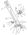
- FIG. 1 shows a single-lipped embodiment of the deep hole drill according to the invention.
- the reference numeral 1 denotes a drill head, which is soldered to a drill shank 15, which in turn is soldered into a clamping sleeve 16.
- the flute is essentially pronounced V-shaped, wherein the spanned by chip and chip flank angle corresponds approximately 90 °.
- the drill head has at its tip on the rake face of the flute 13 has a recess which forms with its rear surface 5 and the two side surfaces 10, 14 a seat for a replaceable cutting plate 2.
- a central threaded bore 7 is drilled, which receives a guided through a through hole in the interchangeable cutting plate 2 screw 6.
- the interchangeable cutting plate 2 has, as well as the guide rails 3 ', a through hole 8, which is aligned with a corresponding threaded hole 7 at a minimum offset, so that a quick screw the interchangeable cutting plate 2 as well as the guide rails 3' each with a single screw. 6 is possible.
- the fixed stop for the guide rails respectively consists of the rear surface 9 of the guide rail seat on the drill head, while the width of the guide rails is the same for all nominal diameters.
- the guide rails of the kits for different nominal diameters thus differ only by their radial thickness, i. the distance between outer peripheral surface and counter stop surface 109, which is predetermined by the respective nominal diameter of the tool.
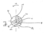
- Fig. 4 shows an enlarged plan view of the built-in removable disk 2.
- the through-hole 8 - drawn in a solid line - and the threaded hole 7 - drawn in dashed line - are mutually at a small offset, which leads to screwing the indexable insert 2 to the plate 2 with its counter-abutment side surface 110 is urged against the abutment side surface 10 of the cutting edge seat.
- this offset is clearly oversized.
- the plate 2 with its second orthogonal first counter-abutment side surface 114 abuts against a point located on the second abutment side surface 14 of the cutting blade seat and is thus positionally determined by the surfaces 5, 10, 14 in all three coordinate directions.
- the two stop side surfaces 10, 14 are inclined at an angle ⁇ of 80 ° to each other, while the two counter-stop surfaces 110, 114 form an angle ⁇ of 90 °.
- the cutting plate 2 preferably abuts the stop surface 10 with the entire counter stop side 110.
- Fig. 5 shows a modification in which a linear contact of the cutting plate 2 on the stop 10 is achieved in that the base 5 of the cutting edge seat and the stop surface 10 define an angle which is smaller than 90 °, while the back of the cutting plate 2 and the counter stop surface 110th run at 90 ° to each other.
- FIG. 1 shown embodiment of the deep hole drilling tool according to the invention is a single-lip deep hole drill with a cutting edge on the removable plate 2, which is supported via two guide strips 3 on its diameter in the bore.
- this first embodiment of another embodiment is compared, which has only one guide rail 30. It turns out that the invention can also be realized in such a deep hole drilling tool. In this case, the additional advantage occurs that for the internal cooling channel (see outlet openings 12, 11) more space is available.
- kits each consisting of a replaceable cutting plate and two guide rails for equipping the in Fig. 1 shown drilling tool shown.
- the kits cover five nominal diameters ND 1 to ND 5 , which are in a diameter range ⁇ ND (cf. Fig. 6 ).
- ⁇ ND diameter range
- the through hole 8 the counter stop surfaces 110, 114 and the secondary cutting edge 120 and at an associated guide rail, the counter stop surface 109 and the support surface 50 are referred to only on the indexable insert for the largest nominal diameter ND 1 .
- Fig. 6 shows hatched the nominal diameter range ⁇ ND, in which the universally suitable drill head of the deep hole drill Fig. 1 can be adjusted to the five nominal diameters ND 1 to ND 5 by replacing the inserts and guide rails.
- the through hole 8 has here at all cutting the same distance c to the counter-abutment surface 114 and b to the opposite stop surface 110.
- the distance of the through hole to the secondary cutting edge determines the bore diameter of the growing, however, from the value a 0 at nominal diameter ND 5 on, from ND 5 on ND 4 by the value ⁇ a. It can be seen that the radial thickness of the guide strip, ie the length of the through hole (shown in dashed lines) grows accordingly.
Landscapes
- Engineering & Computer Science (AREA)
- Mechanical Engineering (AREA)
- Drilling Tools (AREA)
Priority Applications (1)
| Application Number | Priority Date | Filing Date | Title |
|---|---|---|---|
| SI200331102T SI1572404T2 (sl) | 2002-12-19 | 2003-12-18 | Sveder za globoko vrtanje z izmenljivimi kompleti za razliäśne premere |
Applications Claiming Priority (3)
| Application Number | Priority Date | Filing Date | Title |
|---|---|---|---|
| DE20219754U | 2002-12-19 | ||
| DE20219754U DE20219754U1 (de) | 2002-12-19 | 2002-12-19 | Tieflochbohrer mit auswechselbarem Schneideinsatz und auswechselbarer Führungsleiste |
| PCT/DE2003/004274 WO2004056518A2 (de) | 2002-12-19 | 2003-12-18 | Tieflochbohrer eb800 |
Publications (3)
| Publication Number | Publication Date |
|---|---|
| EP1572404A2 EP1572404A2 (de) | 2005-09-14 |
| EP1572404B1 EP1572404B1 (de) | 2007-11-28 |
| EP1572404B2 true EP1572404B2 (de) | 2012-04-25 |
Family
ID=32186058
Family Applications (1)
| Application Number | Title | Priority Date | Filing Date |
|---|---|---|---|
| EP03799449A Expired - Lifetime EP1572404B2 (de) | 2002-12-19 | 2003-12-18 | Tieflochbohrer mit austauschsätzen für verschiedene durchmesser |
Country Status (8)
| Country | Link |
|---|---|
| US (2) | US20050244237A1 (https=) |
| EP (1) | EP1572404B2 (https=) |
| JP (1) | JP2006510493A (https=) |
| KR (1) | KR20050085844A (https=) |
| AU (1) | AU2003299280A1 (https=) |
| DE (3) | DE20219754U1 (https=) |
| SI (1) | SI1572404T2 (https=) |
| WO (1) | WO2004056518A2 (https=) |
Families Citing this family (17)
| Publication number | Priority date | Publication date | Assignee | Title |
|---|---|---|---|---|
| SE527809C2 (sv) * | 2004-06-21 | 2006-06-13 | Sandvik Intellectual Property | Stödlister för borrhuvuden |
| DE102006047496A1 (de) * | 2006-10-05 | 2008-04-10 | Walter Ag | Werkzeug zur spanenden Bearbeitung von Werkstücken |
| DE102006060664A1 (de) | 2006-12-21 | 2008-06-26 | Kennametal Inc. | Schneideinsatz, insbesondere für Aufbohr- und/oder Senkoperationen |
| US20080181735A1 (en) * | 2007-01-25 | 2008-07-31 | Ting Fong Electric & Machinery Co., Ltd. | Method for manufacturing drill cutters and structure thereof |
| DE102009031193A1 (de) * | 2009-06-29 | 2010-12-30 | Botek Präzisionsbohrtechnik Gmbh | Tieflochbohrer |
| CN102639271A (zh) * | 2009-12-08 | 2012-08-15 | 株式会社钨钛合金 | 刃尖更换式切削工具 |
| DE102010012963A1 (de) | 2010-03-25 | 2011-09-29 | Rolf Klenk Gmbh & Co Kg | Bohrwerkzeug |
| DE102011081506B4 (de) | 2011-08-24 | 2024-02-22 | Gühring KG | Rundlaufendes Zerspanungswerkzeug |
| CN103447599A (zh) * | 2012-06-01 | 2013-12-18 | 株式会社日研工作所 | 端铣刀的柄部构造及工具夹持具 |
| CN103706855A (zh) * | 2012-10-01 | 2014-04-09 | 李仕清 | 组合刀具或复合刃刀头 |
| US9216463B2 (en) * | 2013-01-03 | 2015-12-22 | Iscar, Ltd. | Cutting tool and cutting insert having exactly three cutting portions therefor |
| TWI508805B (zh) * | 2014-12-23 | 2015-11-21 | 張新添 | Discarded milling cutter |
| DE102016105354B4 (de) * | 2016-03-22 | 2018-03-22 | Hartmetall-Werkzeugfabrik Paul Horn Gmbh | Spanabhebendes Werkzeug |
| CN109894652B (zh) * | 2017-12-08 | 2021-03-26 | 株式会社泰珂洛 | 刀头更换式钻孔工具 |
| US11524344B2 (en) | 2020-04-22 | 2022-12-13 | Iscar, Ltd. | Rotationally asymmetric cutting insert having a single radially extending cutting-edge portion and rotary cutting tool |
| USD1009108S1 (en) | 2020-09-21 | 2023-12-26 | Kyocera Unimerco Tooling A/S | Drill |
| DE102020005946A1 (de) | 2020-09-29 | 2022-03-31 | Jürgen Flad | Tiefbohrwerkzeug durchflussoptimiert |
Citations (1)
| Publication number | Priority date | Publication date | Assignee | Title |
|---|---|---|---|---|
| US3422706A (en) † | 1965-08-06 | 1969-01-21 | Int Nickel Co | Gun drill |
Family Cites Families (17)
| Publication number | Priority date | Publication date | Assignee | Title |
|---|---|---|---|---|
| US1362871A (en) * | 1918-01-10 | 1920-12-21 | William E Kelly | Boring-bar |
| BE449673A (https=) * | 1942-03-21 | |||
| US3094016A (en) * | 1959-11-20 | 1963-06-18 | Kleine Werner Kurt Max | Trepanning and boring head |
| US3376763A (en) * | 1965-11-19 | 1968-04-09 | Halliburton Co | Boring tools |
| SE347450B (https=) * | 1969-11-24 | 1972-08-07 | Sandvikens Jernverks Ab | |
| US4212569A (en) * | 1977-10-06 | 1980-07-15 | Sandvik Aktiebolag | Tubular drill tool |
| US4240770A (en) * | 1978-08-14 | 1980-12-23 | W. Hegenscheidt Gesellschaft Mbh | Boring tool with a floating knife |
| CH652631A5 (de) | 1981-02-19 | 1985-11-29 | Sig Schweiz Industrieges | Einlippiger tieflochbohrer. |
| US4437802A (en) * | 1981-09-14 | 1984-03-20 | Hall Jr John J | Boring tool having a detachable cutting blade |
| US4666350A (en) * | 1984-01-24 | 1987-05-19 | Nicholas Leo P | Boring bar |
| DE3629033A1 (de) * | 1986-08-27 | 1988-03-10 | Stellram Gmbh | Einlippen-vollbohrer |
| GB2215246A (en) * | 1988-03-04 | 1989-09-20 | Fisher & Co J | Boring tool |
| SE504331C2 (sv) * | 1994-09-12 | 1997-01-13 | Sandvik Ab | Stödlist för borr |
| SE504332C2 (sv) * | 1994-09-12 | 1997-01-13 | Sandvik Ab | Borrverktyg |
| US5971674A (en) * | 1997-10-02 | 1999-10-26 | Drill Masters Of Vermont | Deep hole drill bit |
| JP3286836B2 (ja) * | 1997-10-27 | 2002-05-27 | 日本特殊陶業株式会社 | スローアウェイバイト及びそのシャンク |
| SE517446C2 (sv) * | 1999-06-21 | 2002-06-04 | Sandvik Ab | Stödlist/Ledare |
-
2002
- 2002-12-19 DE DE20219754U patent/DE20219754U1/de not_active Expired - Lifetime
-
2003
- 2003-12-18 EP EP03799449A patent/EP1572404B2/de not_active Expired - Lifetime
- 2003-12-18 WO PCT/DE2003/004274 patent/WO2004056518A2/de not_active Ceased
- 2003-12-18 AU AU2003299280A patent/AU2003299280A1/en not_active Abandoned
- 2003-12-18 DE DE50308708T patent/DE50308708D1/de not_active Expired - Lifetime
- 2003-12-18 JP JP2004561064A patent/JP2006510493A/ja active Pending
- 2003-12-18 SI SI200331102T patent/SI1572404T2/sl unknown
- 2003-12-18 DE DE10394164T patent/DE10394164D2/de not_active Expired - Fee Related
- 2003-12-18 KR KR1020057011613A patent/KR20050085844A/ko not_active Ceased
-
2005
- 2005-06-16 US US11/154,770 patent/US20050244237A1/en not_active Abandoned
-
2007
- 2007-01-03 US US11/619,311 patent/US7296953B2/en not_active Expired - Lifetime
Patent Citations (1)
| Publication number | Priority date | Publication date | Assignee | Title |
|---|---|---|---|---|
| US3422706A (en) † | 1965-08-06 | 1969-01-21 | Int Nickel Co | Gun drill |
Non-Patent Citations (8)
| Title |
|---|
| "Auszug aus dem "Katalog 5020-2D" der Firma Hertel AG", February 1986 (1986-02-01) † |
| "Auszug aus dem Prospekt "1000 D Werkzeuge für Bearbeitungszentren" der Firma Hertel AG, gedruckt November 1990", November 1990 (1990-11-01) † |
| "Auszug aus dem Prospekt "botek-Vollbohrkopf Typ 42" der Firma botek Präzisionsbohrtechnik GmbH, gedruckt April 2002", April 2002 (2002-04-01) † |
| "Datenblatt "Tiefbohrwerkzeuge Typ 01" der Firma botek Präzisionstechnik GmbH", 24 February 1999 (1999-02-24) † |
| "Kopien von Zeichnungen und Verkausunterlagen für den "Aufbohrkopf Typ 32" der Firma botek Präzisionstechnik GmbH, teilweise datiert 1998", 1998 † |
| "Prospekt "Vollbohrköpfe Typ 11 / Typ 61" der Firma botek Präzisionstechnik GmbH", May 2001 (2001-05-01) † |
| "VDI-Richtlinie 3210", June 1974 (1974-06-01) † |
| "VDI-Richtlinie 3210, Blatt 1, Punkt 1", March 2006 (2006-03-01) † |
Also Published As
| Publication number | Publication date |
|---|---|
| SI1572404T1 (sl) | 2008-04-30 |
| SI1572404T2 (sl) | 2012-09-28 |
| AU2003299280A8 (en) | 2004-07-14 |
| WO2004056518A2 (de) | 2004-07-08 |
| DE20219754U1 (de) | 2004-04-22 |
| EP1572404A2 (de) | 2005-09-14 |
| JP2006510493A (ja) | 2006-03-30 |
| DE10394164D2 (de) | 2005-11-03 |
| AU2003299280A1 (en) | 2004-07-14 |
| EP1572404B1 (de) | 2007-11-28 |
| DE50308708D1 (de) | 2008-01-10 |
| KR20050085844A (ko) | 2005-08-29 |
| US20050244237A1 (en) | 2005-11-03 |
| US7296953B2 (en) | 2007-11-20 |
| US20070110529A1 (en) | 2007-05-17 |
| WO2004056518A3 (de) | 2004-08-19 |
Similar Documents
| Publication | Publication Date | Title |
|---|---|---|
| EP1572404B2 (de) | Tieflochbohrer mit austauschsätzen für verschiedene durchmesser | |
| EP0404883B1 (de) | Bohr-/faswerkzeug | |
| EP2542369B1 (de) | Führungsleiste | |
| EP2318166B1 (de) | Werkzeug für spanende bearbeitung eines werkstücks | |
| EP1827742B1 (de) | Bohrer für ein bohr-/faswerkzeug und bohr-/faswerkzeug | |
| DE102018102635B4 (de) | Spiralbohrer mit einem ungleichen spannutenabstand und ungleichen freiwinkeln | |
| DE102008025962A1 (de) | Reibahle | |
| WO1996014954A1 (de) | Bohrwerkzeug | |
| DE102005047510A1 (de) | Spanabtragendes Werkzeug | |
| DE102016221363A1 (de) | Bohrwerkzeug und Verfahren zum Herstellen von Bohrungen | |
| DE20219753U1 (de) | Tieflochbohrer | |
| DE102009030470B4 (de) | Wechselkopfhalter-System und Werkzeugkopfelement | |
| EP4257271A1 (de) | Spanabhebendes werkzeug mit einstellbarer führungsleiste | |
| DE102007038935A1 (de) | Stabmesserkopf und entsprechende Werkzeugmaschine | |
| DE102011112952B3 (de) | Reibwerkzeug sowie Einstellschraube für einen Feineinstellmechanismus insbesondere bei einem Reibwerkzeug | |
| DE102022119393A1 (de) | Wendeschneidplattenbohreranordnung mit kühlmittelsystem | |
| DE102004008166A1 (de) | Werkzeug zur spanenden Bearbeitung von Präzisionsbohrungen | |
| DE102010003569A1 (de) | Methode zur Montage eines Innenrundschleifwerkzeugs | |
| DE102004053511B4 (de) | Schneidwerkzeug | |
| WO2007041995A1 (de) | Zerspanungswerkzeug mit schneidenbeschichtung | |
| DE4341503A1 (de) | Vorrichtung zum Feinbearbeiten von Bohrungen | |
| DE102004012619B4 (de) | Schneidplatte sowie Vorrichtung zur Herstellung von Bohrern | |
| DE102004008167A1 (de) | Aufbohrwerkzeug | |
| DE20305081U1 (de) | Spann- und Justiervorrichtung für ein Zerspanungswerkzeug | |
| EP3810362B1 (de) | Bohrwerkzeug |
Legal Events
| Date | Code | Title | Description |
|---|---|---|---|
| PUAI | Public reference made under article 153(3) epc to a published international application that has entered the european phase |
Free format text: ORIGINAL CODE: 0009012 |
|
| 17P | Request for examination filed |
Effective date: 20050524 |
|
| AK | Designated contracting states |
Kind code of ref document: A2 Designated state(s): AT BE BG CH CY CZ DE DK EE ES FI FR GB GR HU IE IT LI LU MC NL PT RO SE SI SK TR |
|
| AX | Request for extension of the european patent |
Extension state: AL LT LV MK |
|
| RIC1 | Information provided on ipc code assigned before grant |
Ipc: B23B 51/04 20060101AFI20060201BHEP |
|
| DAX | Request for extension of the european patent (deleted) | ||
| GRAP | Despatch of communication of intention to grant a patent |
Free format text: ORIGINAL CODE: EPIDOSNIGR1 |
|
| RTI1 | Title (correction) |
Free format text: DEEP HOLE DRILL WITH REPLACEMENT SETS FOR DIFFERENT DIAMETERS |
|
| GRAS | Grant fee paid |
Free format text: ORIGINAL CODE: EPIDOSNIGR3 |
|
| GRAA | (expected) grant |
Free format text: ORIGINAL CODE: 0009210 |
|
| AK | Designated contracting states |
Kind code of ref document: B1 Designated state(s): AT BE BG CH CY CZ DE DK EE ES FI FR GB GR HU IE IT LI LU MC NL PT RO SE SI SK TR |
|
| REG | Reference to a national code |
Ref country code: GB Ref legal event code: FG4D Free format text: NOT ENGLISH |
|
| REG | Reference to a national code |
Ref country code: IE Ref legal event code: FG4D Free format text: LANGUAGE OF EP DOCUMENT: GERMAN |
|
| REG | Reference to a national code |
Ref country code: CH Ref legal event code: EP |
|
| REF | Corresponds to: |
Ref document number: 50308708 Country of ref document: DE Date of ref document: 20080110 Kind code of ref document: P |
|
| REG | Reference to a national code |
Ref country code: RO Ref legal event code: EPE |
|
| GBT | Gb: translation of ep patent filed (gb section 77(6)(a)/1977) |
Effective date: 20080128 |
|
| REG | Reference to a national code |
Ref country code: SE Ref legal event code: TRGR |
|
| PG25 | Lapsed in a contracting state [announced via postgrant information from national office to epo] |
Ref country code: ES Free format text: LAPSE BECAUSE OF FAILURE TO SUBMIT A TRANSLATION OF THE DESCRIPTION OR TO PAY THE FEE WITHIN THE PRESCRIBED TIME-LIMIT Effective date: 20080311 Ref country code: NL Free format text: LAPSE BECAUSE OF FAILURE TO SUBMIT A TRANSLATION OF THE DESCRIPTION OR TO PAY THE FEE WITHIN THE PRESCRIBED TIME-LIMIT Effective date: 20071128 |
|
| NLV1 | Nl: lapsed or annulled due to failure to fulfill the requirements of art. 29p and 29m of the patents act | ||
| REG | Reference to a national code |
Ref country code: HU Ref legal event code: AG4A Ref document number: E002779 Country of ref document: HU |
|
| PG25 | Lapsed in a contracting state [announced via postgrant information from national office to epo] |
Ref country code: BG Free format text: LAPSE BECAUSE OF FAILURE TO SUBMIT A TRANSLATION OF THE DESCRIPTION OR TO PAY THE FEE WITHIN THE PRESCRIBED TIME-LIMIT Effective date: 20080228 Ref country code: FI Free format text: LAPSE BECAUSE OF FAILURE TO SUBMIT A TRANSLATION OF THE DESCRIPTION OR TO PAY THE FEE WITHIN THE PRESCRIBED TIME-LIMIT Effective date: 20071128 |
|
| BERE | Be: lapsed |
Owner name: GUHRING, JORG Effective date: 20071231 |
|
| ET | Fr: translation filed | ||
| PG25 | Lapsed in a contracting state [announced via postgrant information from national office to epo] |
Ref country code: DK Free format text: LAPSE BECAUSE OF FAILURE TO SUBMIT A TRANSLATION OF THE DESCRIPTION OR TO PAY THE FEE WITHIN THE PRESCRIBED TIME-LIMIT Effective date: 20071128 Ref country code: MC Free format text: LAPSE BECAUSE OF NON-PAYMENT OF DUE FEES Effective date: 20071231 |
|
| REG | Reference to a national code |
Ref country code: CH Ref legal event code: PL |
|
| PLBI | Opposition filed |
Free format text: ORIGINAL CODE: 0009260 |
|
| PG25 | Lapsed in a contracting state [announced via postgrant information from national office to epo] |
Ref country code: BE Free format text: LAPSE BECAUSE OF NON-PAYMENT OF DUE FEES Effective date: 20071231 Ref country code: PT Free format text: LAPSE BECAUSE OF FAILURE TO SUBMIT A TRANSLATION OF THE DESCRIPTION OR TO PAY THE FEE WITHIN THE PRESCRIBED TIME-LIMIT Effective date: 20080428 |
|
| PLAX | Notice of opposition and request to file observation + time limit sent |
Free format text: ORIGINAL CODE: EPIDOSNOBS2 |
|
| 26 | Opposition filed |
Opponent name: BOTEK PRAEZISIONSBOHRTECHNIK GMBH Effective date: 20080826 |
|
| PG25 | Lapsed in a contracting state [announced via postgrant information from national office to epo] |
Ref country code: CH Free format text: LAPSE BECAUSE OF NON-PAYMENT OF DUE FEES Effective date: 20071231 Ref country code: IE Free format text: LAPSE BECAUSE OF NON-PAYMENT OF DUE FEES Effective date: 20071218 Ref country code: LI Free format text: LAPSE BECAUSE OF NON-PAYMENT OF DUE FEES Effective date: 20071231 |
|
| PG25 | Lapsed in a contracting state [announced via postgrant information from national office to epo] |
Ref country code: EE Free format text: LAPSE BECAUSE OF FAILURE TO SUBMIT A TRANSLATION OF THE DESCRIPTION OR TO PAY THE FEE WITHIN THE PRESCRIBED TIME-LIMIT Effective date: 20071128 Ref country code: GR Free format text: LAPSE BECAUSE OF FAILURE TO SUBMIT A TRANSLATION OF THE DESCRIPTION OR TO PAY THE FEE WITHIN THE PRESCRIBED TIME-LIMIT Effective date: 20080229 |
|
| PLAF | Information modified related to communication of a notice of opposition and request to file observations + time limit |
Free format text: ORIGINAL CODE: EPIDOSCOBS2 |
|
| PLBB | Reply of patent proprietor to notice(s) of opposition received |
Free format text: ORIGINAL CODE: EPIDOSNOBS3 |
|
| PG25 | Lapsed in a contracting state [announced via postgrant information from national office to epo] |
Ref country code: CY Free format text: LAPSE BECAUSE OF FAILURE TO SUBMIT A TRANSLATION OF THE DESCRIPTION OR TO PAY THE FEE WITHIN THE PRESCRIBED TIME-LIMIT Effective date: 20071128 |
|
| PG25 | Lapsed in a contracting state [announced via postgrant information from national office to epo] |
Ref country code: LU Free format text: LAPSE BECAUSE OF NON-PAYMENT OF DUE FEES Effective date: 20071218 |
|
| APAH | Appeal reference modified |
Free format text: ORIGINAL CODE: EPIDOSCREFNO |
|
| APBM | Appeal reference recorded |
Free format text: ORIGINAL CODE: EPIDOSNREFNO |
|
| APBP | Date of receipt of notice of appeal recorded |
Free format text: ORIGINAL CODE: EPIDOSNNOA2O |
|
| APBQ | Date of receipt of statement of grounds of appeal recorded |
Free format text: ORIGINAL CODE: EPIDOSNNOA3O |
|
| APBU | Appeal procedure closed |
Free format text: ORIGINAL CODE: EPIDOSNNOA9O |
|
| PUAH | Patent maintained in amended form |
Free format text: ORIGINAL CODE: 0009272 |
|
| STAA | Information on the status of an ep patent application or granted ep patent |
Free format text: STATUS: PATENT MAINTAINED AS AMENDED |
|
| 27A | Patent maintained in amended form |
Effective date: 20120425 |
|
| AK | Designated contracting states |
Kind code of ref document: B2 Designated state(s): AT BE BG CH CY CZ DE DK EE ES FI FR GB GR HU IE IT LI LU MC NL PT RO SE SI SK TR |
|
| REG | Reference to a national code |
Ref country code: DE Ref legal event code: R102 Ref document number: 50308708 Country of ref document: DE Effective date: 20120425 |
|
| REG | Reference to a national code |
Ref country code: SE Ref legal event code: RPEO |
|
| REG | Reference to a national code |
Ref country code: SK Ref legal event code: T3 Ref document number: E 3061 Country of ref document: SK |
|
| REG | Reference to a national code |
Ref country code: FR Ref legal event code: PLFP Year of fee payment: 13 |
|
| REG | Reference to a national code |
Ref country code: FR Ref legal event code: PLFP Year of fee payment: 14 |
|
| PGFP | Annual fee paid to national office [announced via postgrant information from national office to epo] |
Ref country code: SK Payment date: 20161129 Year of fee payment: 14 |
|
| PGFP | Annual fee paid to national office [announced via postgrant information from national office to epo] |
Ref country code: SI Payment date: 20161122 Year of fee payment: 14 |
|
| REG | Reference to a national code |
Ref country code: FR Ref legal event code: PLFP Year of fee payment: 15 |
|
| PGFP | Annual fee paid to national office [announced via postgrant information from national office to epo] |
Ref country code: TR Payment date: 20171212 Year of fee payment: 15 |
|
| REG | Reference to a national code |
Ref country code: SK Ref legal event code: MM4A Ref document number: E 3061 Country of ref document: SK Effective date: 20171218 |
|
| REG | Reference to a national code |
Ref country code: SI Ref legal event code: KO00 Effective date: 20180806 |
|
| PG25 | Lapsed in a contracting state [announced via postgrant information from national office to epo] |
Ref country code: SK Free format text: LAPSE BECAUSE OF NON-PAYMENT OF DUE FEES Effective date: 20171218 Ref country code: SI Free format text: LAPSE BECAUSE OF NON-PAYMENT OF DUE FEES Effective date: 20171219 |
|
| PGFP | Annual fee paid to national office [announced via postgrant information from national office to epo] |
Ref country code: DK Payment date: 20181123 Year of fee payment: 10 |
|
| PGFP | Annual fee paid to national office [announced via postgrant information from national office to epo] |
Ref country code: CZ Payment date: 20191122 Year of fee payment: 17 Ref country code: SE Payment date: 20191220 Year of fee payment: 17 |
|
| PGFP | Annual fee paid to national office [announced via postgrant information from national office to epo] |
Ref country code: FR Payment date: 20191220 Year of fee payment: 17 Ref country code: IT Payment date: 20191231 Year of fee payment: 17 |
|
| PGFP | Annual fee paid to national office [announced via postgrant information from national office to epo] |
Ref country code: AT Payment date: 20191217 Year of fee payment: 17 |
|
| PGFP | Annual fee paid to national office [announced via postgrant information from national office to epo] |
Ref country code: GB Payment date: 20191220 Year of fee payment: 17 |
|
| PG25 | Lapsed in a contracting state [announced via postgrant information from national office to epo] |
Ref country code: RO Free format text: LAPSE BECAUSE OF NON-PAYMENT OF DUE FEES Effective date: 20191218 |
|
| PG25 | Lapsed in a contracting state [announced via postgrant information from national office to epo] |
Ref country code: HU Free format text: LAPSE BECAUSE OF NON-PAYMENT OF DUE FEES Effective date: 20191219 |
|
| PG25 | Lapsed in a contracting state [announced via postgrant information from national office to epo] |
Ref country code: CZ Free format text: LAPSE BECAUSE OF NON-PAYMENT OF DUE FEES Effective date: 20201218 |
|
| REG | Reference to a national code |
Ref country code: SE Ref legal event code: EUG |
|
| REG | Reference to a national code |
Ref country code: AT Ref legal event code: MM01 Ref document number: 379516 Country of ref document: AT Kind code of ref document: T Effective date: 20201218 |
|
| GBPC | Gb: european patent ceased through non-payment of renewal fee |
Effective date: 20201218 |
|
| PG25 | Lapsed in a contracting state [announced via postgrant information from national office to epo] |
Ref country code: FR Free format text: LAPSE BECAUSE OF NON-PAYMENT OF DUE FEES Effective date: 20201231 Ref country code: AT Free format text: LAPSE BECAUSE OF NON-PAYMENT OF DUE FEES Effective date: 20201218 Ref country code: IT Free format text: LAPSE BECAUSE OF NON-PAYMENT OF DUE FEES Effective date: 20201218 |
|
| PG25 | Lapsed in a contracting state [announced via postgrant information from national office to epo] |
Ref country code: SE Free format text: LAPSE BECAUSE OF NON-PAYMENT OF DUE FEES Effective date: 20201219 Ref country code: GB Free format text: LAPSE BECAUSE OF NON-PAYMENT OF DUE FEES Effective date: 20201218 |
|
| PG25 | Lapsed in a contracting state [announced via postgrant information from national office to epo] |
Ref country code: TR Free format text: LAPSE BECAUSE OF NON-PAYMENT OF DUE FEES Effective date: 20201218 |
|
| PGFP | Annual fee paid to national office [announced via postgrant information from national office to epo] |
Ref country code: DE Payment date: 20221231 Year of fee payment: 20 |
|
| REG | Reference to a national code |
Ref country code: DE Ref legal event code: R071 Ref document number: 50308708 Country of ref document: DE |