EP1571546A1 - Random number generator - Google Patents
Random number generator Download PDFInfo
- Publication number
- EP1571546A1 EP1571546A1 EP03772780A EP03772780A EP1571546A1 EP 1571546 A1 EP1571546 A1 EP 1571546A1 EP 03772780 A EP03772780 A EP 03772780A EP 03772780 A EP03772780 A EP 03772780A EP 1571546 A1 EP1571546 A1 EP 1571546A1
- Authority
- EP
- European Patent Office
- Prior art keywords
- random number
- pseudo
- output
- generating unit
- physical
- Prior art date
- Legal status (The legal status is an assumption and is not a legal conclusion. Google has not performed a legal analysis and makes no representation as to the accuracy of the status listed.)
- Withdrawn
Links
Images


Classifications
-
- G—PHYSICS
- G06—COMPUTING OR CALCULATING; COUNTING
- G06F—ELECTRIC DIGITAL DATA PROCESSING
- G06F7/00—Methods or arrangements for processing data by operating upon the order or content of the data handled
- G06F7/58—Random or pseudo-random number generators
- G06F7/588—Random number generators, i.e. based on natural stochastic processes
-
- G—PHYSICS
- G06—COMPUTING OR CALCULATING; COUNTING
- G06F—ELECTRIC DIGITAL DATA PROCESSING
- G06F7/00—Methods or arrangements for processing data by operating upon the order or content of the data handled
- G06F7/58—Random or pseudo-random number generators
- G06F7/582—Pseudo-random number generators
- G06F7/584—Pseudo-random number generators using finite field arithmetic, e.g. using a linear feedback shift register
Definitions
- the present invention relates to a random number generator, and particularly to a random number generator suitable for an encryption algorithm.
- a random number is often used to ensure security.
- a pseudo-random number is used that is typified by an M-sequence (Maximum Length Code) or the like.
- M-sequence code can be generated using a known linear shift register code generator.
- a random number other than the above described pseudo-random number there is known a physical random number generated using natural phenomena such as the fact that nuclear decay is random, or electrical noise.
- this physical random number is used instead of the above described pseudo-random number (for example, Japanese Patent Laid-open No. 2000-66592).
- a pseudo-random number typified by an M-sequence is not a random number having a high margin of safety, and is therefore not preferred from the point of view of ensuring security. Since a pseudo-random number is generated from a fixed arithmetic process or combination of functions, if the same initial conditions exist, there is a possibility that the same random number will be generated. Also, since a physical random number is generally a faint signal, in order to be used with an encryption algorithm it is normally amplified to a usable level using an amplifier. However, an amplifier can be affected by electrical and magnetic fields, and a random number generation rate is operated on by these intentional impressions, and margin of safety may be adversely reduced.
- a random number generator of the present invention comprises a plurality of pseudo-random number generating unit capable of respectively outputting random numbers of a fixed pseudo-random number sequence, output random number generating unit capable of generating an output random number based on output of the plurality of pseudo-random number generating unit, physical random number generating unit for generating a physical random number, and switching unit for, in generation of an output random number in the output random number generating unit, switching whether or not a pseudo-random number generated by at least one of the pseudo-random number generating unit is used based on a physical random number generated by the physical random number generating unit.
- a pseudo-random number constituting a source of an output random number among a plurality of pseudo-random number sequences is varied based on a physical random number, it is possible to reduce predictability of a random number compared to a related art random number generator that used only a pseudo-random number. Also, since a physical random number is not used as a direct output random number, it becomes difficult to predict the output random number compared to a related art device, even if some operation is applied to the physical random number generating unit from outside.
- the switching unit is also possible for the switching unit to be configured so as to switch whether or not a clock signal is input to at least one of the pseudo-random number generating unit based on the physical random number.
- the switching unit determines whether or not a new pseudo-random number is output from a pseudo-random number generating unit is switched by switching whether or not a clock signal is input to that pseudo-random number generating unit.
- the above described random number generator of the present invention it is also possible to have a configuration where the physical random number generated by the physical random number generating unit is input as at least one of the above described pseudo-random number generating unit clock signal With this configuration, whether or not a new random number is output from a pseudo-random number generating unit is switched by switching the physical random number output value as the clock signal. In this case, the physical random number generating unit functions as the switching unit.
- the switching unit is configured so as to switch whether or not a pseudo-random number generated by at least one of the pseudo-random number generating unit is input to the output random number generating unit based on the physical random number.
- the switching unit determines whether or not a pseudo-random number generated by at least one of the pseudo-random number generating unit is input to the output random number generating unit is switched by the switching unit.
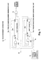
- Fig. 1 is a drawing showing the structure of a random number generator 10 of this embodiment
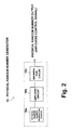
- Fig. 2 is a structural drawing of a physical random number generator 16.
- the random number generator 10 is comprised of two pseudo-random number generating units 12a and 12b, an output random number generating unit 14, a physical random number generating unit 16, and a switching unit 18.
- the pseudo-random number generating units 12a and 12b respectively comprise shift registers 20a, 20b including a plurality of flip-flops that are successively connected, and EXOR gates 22a, 22b for outputting an exclusive-OR of output values from a specified plurality of tap positions, and are configured as linear shift register code generators for outputting a random number of a specified M-sequence.
- the shift register 20a has 17 flip-flops, is a 17 stage shift register for performing bit shift in response to a clock signal, and generates a feedback input value (D1 input of the shift register 20a: "1" (high level) or "0" (low level)) based on tap outputs from a 3rd flip-flop and a 17th flip-flop (Q outputs: Q3, Q17), from the input side.
- the shift register 20b has 15 flip-flops, is a 15 stage shift register for performing bit shifting in response to a clock signal, and generates a feedback input value based on tap outputs from a 2nd flip-flop and a 15th flip-flop (Q2, Q15), from the input side.
- the number of stages and tap positions constituting sources for the feedback input are different for the shift register 20a and the shift register 20b, and the pseudo-random number generating units 12a and 12b can generate different M-sequence codes.
- a clock signal for driving the pseudo-random number generating unit 12a (clock signal for the shift register 20a to perform bit shift) is directly input from a signal source 24, but the clock signal for the pseudo-random number generating unit 12b (shift register 20b) is input from the signal source 24 via a switching unit 18.
- the switching unit 18 switches whether or not a clock signal is input to the pseudo-random number generating unit 12b based on a physical random number output from the physical random number generator 16.
- the switching unit 18 is configured as an AND gate, and makes the value of a shared clock signal input to the pseudo-random number generating unit 12b (that is, an output value) "1" only when the value of a shared clock signal from the signal source 24 is "1" and the physical random number output value is "1".
- a pseudo-random number generated by the pseudo-random number generating unit 12b is only input to the output random number generating unit 14 when the physical random number output value is "1", while on the other and, when the physical random number output value is "0" that output value becomes fixed at the value of a bit connected to that output line (with the example of Fig. 1, the Q15 output of the 15th bit: "1" or "0").
- the output random number generating unit 14 is configured as an EXOR gate, and sets the output value to "1" when the output values from the pseudo-random number generating units 12a and 12b do not match, but sets the output value to "0" when the output values do match.
- the output value of the pseudo-random number generating unit 12b becomes a pseudo-random number, while when the physical random number output value is "0", the output value of the pseudo-random number generator 12b is set to "1" or "0".
- the output random number of the output random number generating unit 14 is generated based on the pseudo-random numbers generated by the two pseudo-random number generating units 12a and 12b, while when the physical random number output value is "0", it is generated based on the pseudo-random number generated by the pseudo-random number generating unit 12a.
- which pseudo-random number is used to generate an output number is changed at random using a physical random number, and compared to a conventional physical random number or pseudo-random number it is extremely difficult to predict.
- the physical random number generator 16 is provided with a physical random number source 16a, an amplifier circuit 16b and a binarizing circuit 16c.
- the physical random number source 16a generates a signal that varies randomly based on a natural phenomenon, and can include, for example, as disclosed in patent publication 1 described above, a semiconductor element for generating a noise signal generated in a current path containing junctions. This is not limiting, however, and it is also possible to use something that utilizes the decay of a radioactive material etc. as this physical random number source 16a.
- a signal generated in the physical random number source 16a is amplified by the amplifier circuit 16b, and then subjected to binarization processing in the binarization circuit 16c.
- the binarization circuit 16c compares amplitude of the amplified signal and a specified threshold, at a specified sampling timing, and, for example, outputs "1" of the amplitude of the amplified signal is higher than the specified threshold, and outputs "0" when the amplitude is lower than the threshold. In this way, a physical random number output value for a specified voltage representing "1” or "0" is generated by the physical random number generator 16.
- the threshold level of the binarization circuit 16c can be set arbitrarily, but is normally set so that the generation probability for "1" and "0" is almost 1:1. In the binarization circuit 16c, it is also possible to simply compare the amplitude of the amplified signal with a specified threshold, to generate an output signal.
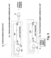
- Fig. 3 is a drawing showing the structure of a random number generator 30 of a this embodiment.
- structural elements that are the same as in the above-described embodiment have the same reference numerals, and description of duplicate sections is omitted.
- a logical AND of a physical random number output from the physical random number generator 16 and a shared clock signal from the signal source 24 is input to the pseudo-random number generating unit 12b as a clock signal, but with this embodiment a clock signal to the pseudo-random number generating unit 12b is actually the physical random number output from the physical random number generator 16.
- the physical random number generator 16 is equivalent to a switching unit.
- the clock signal CK of the pseudo-random number generating unit 12a is input independently from the physical random number output.
- the pseudo-random number generating unit 12b sequentially generates a pseudo-random number at the output timing of the physical random number output (sampling timing of the physical random number generator 16), and outputs this random number to the output random number generating unit 14.
- the pseudo-random number generating unit 12b is not driven, and the output value is fixed to the value of a bit connected to an output line (in Fig. 3, the Q15 output of the 15th bit:"1" or "0").
- the physical random number output value is "1”
- a pseudo-random number is output from the pseudo-random number generating unit 12b in response to the clock signal
- the physical random number output value is "0”
- the pseudo-random number is not output but is in a state fixed to an output value.
- an output random number output from the output random number generating unit 14 is the same as with the first embodiment described above.
- Fig. 4 is a drawing showing the structure of a random number generator 40 of this embodiment.
- structural elements that are the same as in the above-described embodiment have the same reference numerals, and description of duplicate sections is omitted.
- a pseudo-random number generated by the pseudo-random number generating unit 12b is input to the output random number generating unit 14 is controlled using a switching unit 48.
- output of the pseudo-random number generating unit 12b is input to the output random number generating unit 14 via a switching unit 48 configured as an AND gate.
- a switching unit 48 configured as an AND gate.
- a logical AND of the physical random number output from the physical random number generator 16 and the output of the pseudo-random number generating unit 12b is acquired, and this logical AND is input to the output random number generating unit 14.
- the output random number generating unit 14 acquires an exclusive OR of the pseudo-random numbers of the two pseudo-random number generating units 12a and 12b, and outputs this as an output random number.
- the physical random number output value is "0”
- "0” is input to the output random number generating unit 14 and an output random number having the same value as the output value of the pseudo-random number generating unit 12a (namely the pseudo-random number output from the pseudo-random number generating unit 12a) is output from the output random number generating unit 14.
- a pseudo-random number is output from the pseudo-random number generating unit 12b in response to the clock signal (for example, a clock signal shared with the pseudo-random number generating unit 12a), and when the physical random number output value is "0" the pseudo-random number is not output but is in a state fixed to an output value.
- the clock signal for example, a clock signal shared with the pseudo-random number generating unit 12a
- which pseudo-random number is the basis for generating an output state is changed at random using a physical random number, and compared to a conventional physical random number or pseudo-random number it is extremely difficult to predict.
- Fig. 5 is a drawing showing the structure of a random number generator 50 of this embodiment.
- structural elements that are the same as in the above-described embodiment have the same reference numerals, and description of duplicate sections is omitted.
- whether or not pseudo-random numbers respectively generated by the pseudo-random number generating units 12a and 12b are input to the output random number generating unit 14 is switched using a physical random number output value.
- one or other of the pseudo-random numbers generated by the pseudo-random number generating units 12a and 12b is selectively input to the output random number generating unit 14, and a selectively input pseudo-random number constitutes output of the output random number generating unit 14 as is, namely, output of the random number generator 50. That is, with the example of Fig. 5, which of the pseudo-random number patters respectively generated by the plurality of pseudo-random number generators 12a, 12b is output can be selectively switched using a physical random number.
- the switching unit 58 is provided with two AND gates 58a and 58b, with one of the AND gates 58a being input with the output of the pseudo-random number generating unit 12a, and a physical random number output value from the physical random number generator 16 via an inverter 58c, while the other AND gate 58b is input with the output of the pseudo-random number generating unit 12b and a physical random number output value from the physical random number generator 16. Outputs of these AND gates 58a and 58b are then input to the output random number generating unit 14, and an exclusive OR of these outputs becomes the output random number.
- the pseudo-random number generated by the pseudo-random number generating unit 12a is input as is to the output random number generating unit 14 as output of the AND gate 58a, while the output of the other AND gate 58b is "0".
- an output random number having the same value as the output value of the pseudo-random number generating unit 12a (namely the pseudo-random number output from the pseudo-random number generating unit 12a) is output from the output random number generating unit 14.
- which pseudo-random number is used to generate an output random number is changed at random using a physical random number, and compared to a conventional physical random number or pseudo-random number it is extremely difficult to predict.
- a pseudo-random number is several types of M-sequence code generated by linear shift register code generators having 17 stage or 15 stage shift registers, but this example is not limiting, and it is also possible to have pseudo-random number sequences based on shift registers with a different number of stages or a combination of taps. It is also possible for a plurality of pseudo-random number generating units to generate pseudo-random numbers for the same sequence.
- a Q output from a flip-flop of the final stage of the shift register is output as the pseudo-random number, but it is also possible to output the pseudo-random number from another flip-flop, or to output a feedback value input to the shift register as the pseudo-random number.
Landscapes
- Engineering & Computer Science (AREA)
- Theoretical Computer Science (AREA)
- General Physics & Mathematics (AREA)
- Physics & Mathematics (AREA)
- Mathematical Analysis (AREA)
- Pure & Applied Mathematics (AREA)
- Mathematical Optimization (AREA)
- General Engineering & Computer Science (AREA)
- Computational Mathematics (AREA)
- Tests Of Electronic Circuits (AREA)
- Test And Diagnosis Of Digital Computers (AREA)
- Pinball Game Machines (AREA)
- Manipulation Of Pulses (AREA)
Abstract
Description
Claims (5)
- A random number generator comprising:a plurality of pseudo-random number generating unit capable of respectively outputting random numbers of a fixed pseudo-random number sequence;output random number generating unit capable of generating an output random number based on output of the plurality of pseudo-random number generating unit;physical random number generating unit for generating a physical random number; andswitching unit for, in generation of an output random number in the output random number generating unit, switching whether or not a pseudo-random number generated by at least one of the pseudo-random number generating unit is used based on a physical random number generated by the physical random number generating unit.
- The random number generator of claim 1, wherein the switching unit switches whether or not a clock signal is input to at least one of the pseudo-random number generating unit based on the physical random number.
- The random number generator of claim 1, wherein a physical random number generated by the physical random number generating unit is input as a clock signal of at least one of the pseudo-random number generating unit.
- The random number generator of claim 1, wherein the switching unit switches whether or not a pseudo-random number generated by at least one of the pseudo-random number generating unit is input to the output random number generating unit based on the physical random number.
- The random number generator of claim 1, wherein the output random number generating unit is an exclusive OR gate.
Applications Claiming Priority (3)
| Application Number | Priority Date | Filing Date | Title |
|---|---|---|---|
| JP2002331884 | 2002-11-15 | ||
| JP2002331884A JP4288057B2 (en) | 2002-11-15 | 2002-11-15 | Random number generator |
| PCT/JP2003/014517 WO2004046912A1 (en) | 2002-11-15 | 2003-11-14 | Random number generator |
Publications (2)
| Publication Number | Publication Date |
|---|---|
| EP1571546A1 true EP1571546A1 (en) | 2005-09-07 |
| EP1571546A4 EP1571546A4 (en) | 2007-12-05 |
Family
ID=32321643
Family Applications (1)
| Application Number | Title | Priority Date | Filing Date |
|---|---|---|---|
| EP03772780A Withdrawn EP1571546A4 (en) | 2002-11-15 | 2003-11-14 | Random number generator |
Country Status (5)
| Country | Link |
|---|---|
| US (1) | US20060179094A1 (en) |
| EP (1) | EP1571546A4 (en) |
| JP (1) | JP4288057B2 (en) |
| TW (1) | TWI262434B (en) |
| WO (1) | WO2004046912A1 (en) |
Cited By (1)
| Publication number | Priority date | Publication date | Assignee | Title |
|---|---|---|---|---|
| US8126140B2 (en) | 2004-08-02 | 2012-02-28 | France Telecom | Generation of a pseudorandom data sequence |
Families Citing this family (12)
| Publication number | Priority date | Publication date | Assignee | Title |
|---|---|---|---|---|
| US8183980B2 (en) * | 2005-08-31 | 2012-05-22 | Assa Abloy Ab | Device authentication using a unidirectional protocol |
| JP4912772B2 (en) * | 2005-09-22 | 2012-04-11 | 富士通株式会社 | Encryption method, encryption / decryption method, encryption device, encryption / decryption device, transmission / reception system, and communication system |
| JP4829628B2 (en) * | 2005-10-31 | 2011-12-07 | 富士通株式会社 | Encryption method, encryption / decryption method, encryption device, encryption / decryption device, and communication system |
| JP4955415B2 (en) * | 2007-02-20 | 2012-06-20 | 株式会社エルイーテック | Information communication apparatus and information communication method using a plurality of random number sequences |
| DK2156282T3 (en) * | 2007-05-10 | 2013-03-25 | Dis Ent Llc | Non-deterministic statistical data generator |
| EP2316180A4 (en) | 2008-08-11 | 2011-12-28 | Assa Abloy Ab | Secure wiegand communications |
| WO2011102866A2 (en) * | 2009-11-25 | 2011-08-25 | Aclara RF Systems Inc. | Random number generator |
| KR20120082230A (en) * | 2011-01-13 | 2012-07-23 | 에스케이하이닉스 주식회사 | Semiconductor apparatus and semiconductor system having random code generation circuit and method of programming data |
| US9660803B2 (en) * | 2015-09-15 | 2017-05-23 | Global Risk Advisors | Device and method for resonant cryptography |
| US10452877B2 (en) | 2016-12-16 | 2019-10-22 | Assa Abloy Ab | Methods to combine and auto-configure wiegand and RS485 |
| DE102019201094A1 (en) * | 2019-01-29 | 2020-07-30 | Robert Bosch Gmbh | Data processing device and method for operating a data processing device |
| US11126404B2 (en) * | 2019-05-20 | 2021-09-21 | Nxp B.V. | Random number generator using multiple entropy sources and a method for generating random numbers |
Family Cites Families (11)
| Publication number | Priority date | Publication date | Assignee | Title |
|---|---|---|---|---|
| JPS6025611Y2 (en) * | 1980-04-21 | 1985-08-01 | ニコ−電子株式会社 | Random number generation circuit |
| JPS61246787A (en) * | 1985-03-27 | 1986-11-04 | 富士通株式会社 | Random number mixing system |
| JPS62144243A (en) * | 1985-12-18 | 1987-06-27 | Nec Corp | Random number generator |
| US4852023A (en) * | 1987-05-12 | 1989-07-25 | Communications Satellite Corporation | Nonlinear random sequence generators |
| US5963104A (en) * | 1996-04-15 | 1999-10-05 | Vlsi Technology, Inc. | Standard cell ring oscillator of a non-deterministic randomizer circuit |
| US6253223B1 (en) * | 1999-06-08 | 2001-06-26 | General Instrument Corporation | Robust random number generator |
| JP2001344094A (en) * | 2000-05-31 | 2001-12-14 | Ntt Electornics Corp | Random number generator |
| US6807553B2 (en) * | 2001-04-23 | 2004-10-19 | Safenet B.V. | Digital true random number generator circuit |
| US7139397B2 (en) * | 2001-07-20 | 2006-11-21 | Stmicroelectronics S.R.L. | Hybrid architecture for realizing a random numbers generator |
| US7142675B2 (en) * | 2002-02-12 | 2006-11-28 | City University Of Hong Kong | Sequence generator and method of generating a pseudo random sequence |
| US7028059B2 (en) * | 2002-06-24 | 2006-04-11 | Sun Microsystems, Inc. | Apparatus and method for random number generation |
-
2002
- 2002-11-15 JP JP2002331884A patent/JP4288057B2/en not_active Expired - Fee Related
-
2003
- 2003-11-14 EP EP03772780A patent/EP1571546A4/en not_active Withdrawn
- 2003-11-14 US US10/534,775 patent/US20060179094A1/en not_active Abandoned
- 2003-11-14 TW TW092131942A patent/TWI262434B/en active
- 2003-11-14 WO PCT/JP2003/014517 patent/WO2004046912A1/en not_active Ceased
Cited By (1)
| Publication number | Priority date | Publication date | Assignee | Title |
|---|---|---|---|---|
| US8126140B2 (en) | 2004-08-02 | 2012-02-28 | France Telecom | Generation of a pseudorandom data sequence |
Also Published As
| Publication number | Publication date |
|---|---|
| EP1571546A4 (en) | 2007-12-05 |
| JP2004164482A (en) | 2004-06-10 |
| TWI262434B (en) | 2006-09-21 |
| US20060179094A1 (en) | 2006-08-10 |
| JP4288057B2 (en) | 2009-07-01 |
| TW200421171A (en) | 2004-10-16 |
| WO2004046912A1 (en) | 2004-06-03 |
Similar Documents
| Publication | Publication Date | Title |
|---|---|---|
| US20060179094A1 (en) | Random number generator | |
| KR19980070252A (en) | Pseudorandom Number Generation Circuit and Data Communication System Employing the Same | |
| KR20020008849A (en) | Robust random number generator | |
| CN111694545A (en) | Random number generator | |
| US20090204656A1 (en) | Pseudo random number generator and method for generating a pseudo random number bit sequence | |
| JP2003131867A (en) | Random number generator | |
| JP4417389B2 (en) | Random number generator and method using digital logic | |
| TWI579763B (en) | Storage circuit with random number generation mode | |
| KR100855599B1 (en) | Semiconductor device having power consumption analysis preventing function | |
| US20060123072A1 (en) | Random number generation device | |
| CN1957384B (en) | Electronic element and data processing method | |
| JPH10320181A (en) | Nonlinear feedback shift register circuit | |
| Rudra et al. | Designing stealthy trojans with sequential logic: A stream cipher case study | |
| KR20140037155A (en) | Method for securely checking a code | |
| US20040128332A1 (en) | Method for generating rendom number and random number generator | |
| AU760029B2 (en) | Random signal generator and method for generating a random signals | |
| JPH10308720A (en) | Circuit for arbitrarily shifting M-sequence | |
| KR100735953B1 (en) | Device and method for generating a sequence of numbers | |
| Alspector et al. | Generating multiple analog noise sources from a single linear feedback shift register with neural network applications | |
| KR100209218B1 (en) | Variable frequency clock generation circuit | |
| JP2792242B2 (en) | Scrambler with inversion circuit | |
| US7502814B2 (en) | Device and method for generating a pseudorandom sequence of numbers | |
| KR100307705B1 (en) | Layered orthogonal code generation apparatus and method | |
| JPS5843743B2 (en) | Encryption method | |
| KR100421852B1 (en) | apparatus for generating multiple PN chips |
Legal Events
| Date | Code | Title | Description |
|---|---|---|---|
| PUAI | Public reference made under article 153(3) epc to a published international application that has entered the european phase |
Free format text: ORIGINAL CODE: 0009012 |
|
| 17P | Request for examination filed |
Effective date: 20050614 |
|
| AK | Designated contracting states |
Kind code of ref document: A1 Designated state(s): AT BE BG CH CY CZ DE DK EE ES FI FR GB GR HU IE IT LI LU MC NL PT RO SE SI SK TR |
|
| AX | Request for extension of the european patent |
Extension state: AL LT LV MK |
|
| DAX | Request for extension of the european patent (deleted) | ||
| RBV | Designated contracting states (corrected) |
Designated state(s): DE FR GB IT NL |
|
| RIN1 | Information on inventor provided before grant (corrected) |
Inventor name: IKETANI, AKIRA,SANYO SEMICON DEVICE CO., LTD. Inventor name: TAMAKI, HARUO,KK SURI SEKKEI KENKYUSHO Inventor name: ONAYA, MASATO,SANYO ELECTRIC CO., LTD. |
|
| A4 | Supplementary search report drawn up and despatched |
Effective date: 20071105 |
|
| 17Q | First examination report despatched |
Effective date: 20080221 |
|
| GRAP | Despatch of communication of intention to grant a patent |
Free format text: ORIGINAL CODE: EPIDOSNIGR1 |
|
| STAA | Information on the status of an ep patent application or granted ep patent |
Free format text: STATUS: THE APPLICATION IS DEEMED TO BE WITHDRAWN |
|
| 18D | Application deemed to be withdrawn |
Effective date: 20090610 |