EP1571532A2 - Redundant liquid cooling system and electronic apparatus having the same therein - Google Patents
Redundant liquid cooling system and electronic apparatus having the same therein Download PDFInfo
- Publication number
- EP1571532A2 EP1571532A2 EP04005450A EP04005450A EP1571532A2 EP 1571532 A2 EP1571532 A2 EP 1571532A2 EP 04005450 A EP04005450 A EP 04005450A EP 04005450 A EP04005450 A EP 04005450A EP 1571532 A2 EP1571532 A2 EP 1571532A2
- Authority
- EP
- European Patent Office
- Prior art keywords
- circulation
- liquid coolant
- cooling system
- cooling
- electronic apparatus
- Prior art date
- Legal status (The legal status is an assumption and is not a legal conclusion. Google has not performed a legal analysis and makes no representation as to the accuracy of the status listed.)
- Withdrawn
Links
Images






Classifications
-
- H—ELECTRICITY
- H10—SEMICONDUCTOR DEVICES; ELECTRIC SOLID-STATE DEVICES NOT OTHERWISE PROVIDED FOR
- H10W—GENERIC PACKAGES, INTERCONNECTIONS, CONNECTORS OR OTHER CONSTRUCTIONAL DETAILS OF DEVICES COVERED BY CLASS H10
- H10W40/00—Arrangements for thermal protection or thermal control
- H10W40/40—Arrangements for thermal protection or thermal control involving heat exchange by flowing fluids
- H10W40/47—Arrangements for thermal protection or thermal control involving heat exchange by flowing fluids by flowing liquids, e.g. forced water cooling
-
- B—PERFORMING OPERATIONS; TRANSPORTING
- B65—CONVEYING; PACKING; STORING; HANDLING THIN OR FILAMENTARY MATERIAL
- B65H—HANDLING THIN OR FILAMENTARY MATERIAL, e.g. SHEETS, WEBS, CABLES
- B65H75/00—Storing webs, tapes, or filamentary material, e.g. on reels
- B65H75/02—Cores, formers, supports, or holders for coiled, wound, or folded material, e.g. reels, spindles, bobbins, cop tubes, cans, mandrels or chucks
- B65H75/34—Cores, formers, supports, or holders for coiled, wound, or folded material, e.g. reels, spindles, bobbins, cop tubes, cans, mandrels or chucks specially adapted or mounted for storing and repeatedly paying-out and re-storing lengths of material provided for particular purposes, e.g. anchored hoses, power cables
- B65H75/38—Cores, formers, supports, or holders for coiled, wound, or folded material, e.g. reels, spindles, bobbins, cop tubes, cans, mandrels or chucks specially adapted or mounted for storing and repeatedly paying-out and re-storing lengths of material provided for particular purposes, e.g. anchored hoses, power cables involving the use of a core or former internal to, and supporting, a stored package of material
- B65H75/44—Constructional details
- B65H75/48—Automatic re-storing devices
- B65H75/486—Arrangements or adaptations of the spring motor
-
- G—PHYSICS
- G06—COMPUTING OR CALCULATING; COUNTING
- G06F—ELECTRIC DIGITAL DATA PROCESSING
- G06F1/00—Details not covered by groups G06F3/00 - G06F13/00 and G06F21/00
- G06F1/16—Constructional details or arrangements
- G06F1/20—Cooling means
-
- G—PHYSICS
- G06—COMPUTING OR CALCULATING; COUNTING
- G06F—ELECTRIC DIGITAL DATA PROCESSING
- G06F1/00—Details not covered by groups G06F3/00 - G06F13/00 and G06F21/00
- G06F1/16—Constructional details or arrangements
- G06F1/20—Cooling means
- G06F1/206—Cooling means comprising thermal management
-
- H—ELECTRICITY
- H05—ELECTRIC TECHNIQUES NOT OTHERWISE PROVIDED FOR
- H05K—PRINTED CIRCUITS; CASINGS OR CONSTRUCTIONAL DETAILS OF ELECTRIC APPARATUS; MANUFACTURE OF ASSEMBLAGES OF ELECTRICAL COMPONENTS
- H05K7/00—Constructional details common to different types of electric apparatus
- H05K7/20—Modifications to facilitate cooling, ventilating, or heating
- H05K7/20709—Modifications to facilitate cooling, ventilating, or heating for server racks or cabinets; for data centers, e.g. 19-inch computer racks
- H05K7/20763—Liquid cooling without phase change
- H05K7/20772—Liquid cooling without phase change within server blades for removing heat from heat source
-
- B—PERFORMING OPERATIONS; TRANSPORTING
- B65—CONVEYING; PACKING; STORING; HANDLING THIN OR FILAMENTARY MATERIAL
- B65H—HANDLING THIN OR FILAMENTARY MATERIAL, e.g. SHEETS, WEBS, CABLES
- B65H2402/00—Constructional details of the handling apparatus
- B65H2402/50—Machine elements
- B65H2402/54—Springs, e.g. helical or leaf springs
-
- B—PERFORMING OPERATIONS; TRANSPORTING
- B65—CONVEYING; PACKING; STORING; HANDLING THIN OR FILAMENTARY MATERIAL
- B65H—HANDLING THIN OR FILAMENTARY MATERIAL, e.g. SHEETS, WEBS, CABLES
- B65H2403/00—Power transmission; Driving means
- B65H2403/90—Machine drive
- B65H2403/94—Other features of machine drive
- B65H2403/946—Means for restitution of accumulated energy, e.g. flywheel, spring
-
- F—MECHANICAL ENGINEERING; LIGHTING; HEATING; WEAPONS; BLASTING
- F28—HEAT EXCHANGE IN GENERAL
- F28D—HEAT-EXCHANGE APPARATUS, NOT PROVIDED FOR IN ANOTHER SUBCLASS, IN WHICH THE HEAT-EXCHANGE MEDIA DO NOT COME INTO DIRECT CONTACT
- F28D21/00—Heat-exchange apparatus not covered by any of the groups F28D1/00 - F28D20/00
- F28D2021/0019—Other heat exchangers for particular applications; Heat exchange systems not otherwise provided for
- F28D2021/0028—Other heat exchangers for particular applications; Heat exchange systems not otherwise provided for for cooling heat generating elements, e.g. for cooling electronic components or electric devices
- F28D2021/0029—Heat sinks
-
- F—MECHANICAL ENGINEERING; LIGHTING; HEATING; WEAPONS; BLASTING
- F28—HEAT EXCHANGE IN GENERAL
- F28F—DETAILS OF HEAT-EXCHANGE AND HEAT-TRANSFER APPARATUS, OF GENERAL APPLICATION
- F28F2265/00—Safety or protection arrangements; Arrangements for preventing malfunction
-
- G—PHYSICS
- G06—COMPUTING OR CALCULATING; COUNTING
- G06F—ELECTRIC DIGITAL DATA PROCESSING
- G06F2200/00—Indexing scheme relating to G06F1/04 - G06F1/32
- G06F2200/20—Indexing scheme relating to G06F1/20
- G06F2200/201—Cooling arrangements using cooling fluid
Definitions
- the present invention relates to an electronic apparatus, such as, a personal computer, being so-called a desktop-type or a notebook-type, or a server, etc., and in particular, it relates to an electronic apparatus having a liquid cooling system therein, being able to cool down a heat-generation element mounted within an inside thereof, such as, a semiconductor integrated circuit (IC), effectively with an aid of a liquid refrigerant or coolant, as well as, the cooling system thereof.
- a liquid cooling system therein, being able to cool down a heat-generation element mounted within an inside thereof, such as, a semiconductor integrated circuit (IC), effectively with an aid of a liquid refrigerant or coolant, as well as, the cooling system thereof.
- IC semiconductor integrated circuit
- cooling is necessary for the heat-generation element, such as, the semiconductor IC element, being mounted within electronic apparatuses, including personal computers, being so-called the desktop-type and the notebook-type, as well as, a server, etc., and in particular, the heat-generation element, such as, a CPU (Central Processing Unit), as a representative one thereof, for example.
- the cooling is achieved generally by using a heat transfer element, being so-called a heat sink that is formed with fins thereon, as well as a fan, being provided for sending a cooling air thereto.
- an element being so-called by a heat-receiving (or cooler) jacket is mounted on the surface of the heat-generating element, i.e., the CPU, directly, while conducting the liquid coolant within a flow passage formed within the heat-receiving jacket, so as to transmit or convey the heat generated from the CPU to the coolant flowing within the jacket mentioned above, thereby cooling down the heat-generating element with high efficiency.
- a heat cycle is made up with the cooler jacket, as the heat-receiving portion thereof, and in more details thereof, it comprises a circulation pump for circulating the liquid coolant mentioned above within the cycle, so-called a radiator, being a heat-radiation portion for irradiating heat of the liquid coolant mentioned above into an outside, and further a coolant tank provided in a part of the cycle depending on the necessity thereof. And, those are connected through a tube made of a metal and/or an elastic material, such as rubber, or the like.
- the circulation pump being provided in a part of the heat cycle for driving the liquid coolant, is normally only one (1) piece, and therefore, in a case when this circulation pump is in trouble due to any reason, it is impossible to circulate the coolant within the heat cycle building up the cooling system.
- the heat-generation element i.e., the CPU
- the heat-generation element comes to be high in the temperature thereof due to the heat generation of itself, and it falls down into the so-called thermal runaway, or the thermal breakdown depending on the cases, thereby causing a trouble or/and stoppage (or stall) of the apparatus.
- the personal computer with provision of such a means for detecting the trouble or failure of this circulation pump, thereby warning a user of the trouble detected therewith, through such as an alarm lamp or the like, for example, it is possible to avoid the trouble/stoppage of the apparatus due to such the trouble of the circulation pump, through letting the user to stop the operation of an apparatus once, so as to repair the pump in the trouble or to exchange it with a new one.
- an object thereof is to provide a liquid cooling system, being suitable to be used in such the personal computer, being so-called the desktop-type or the notebook-type, and also the server, etc., being high in the cooling efficiency thereof, and also having redundancy, as well as, an electronic apparatus having such the cooling system therein.
- an electronic apparatus installing a semiconductor element generating heart within an inside of a housing, thereby necessitating cooling for maintaining a normal operation thereof, and including a cooling system within the inside of said housing or in a portion thereof, said cooling system comprising: a cooling jacket being thermally connected to the semiconductor element, for transmitting heat generated therefrom into a liquid coolant flowing inside thereof; a radiator for radiating the heat transmitted into the liquid coolant in said cooling jacket into an outside of the apparatus; and a circulation pump for circulating said liquid coolant within a loop, including said cooling jacket and said radiator therein, wherein: said circulation pump is provided in a plural number thereof, and further including means for maintaining circulation of said liquid coolant, if one of said plural number of circulation pumps stops function thereof, through the others thereof.
- liquid coolant circulation maintaining means comprises flow passages, being connected to said two (2) sets of circulation pumps, respectively, and check valves, each being attached to a portion of each of the flow passages, or, wherein two (2) sets of said circulation pumps are connected in parallel, and said liquid coolant circulation maintaining means comprises a three-way valve connected to said two (2) sets of circulation pumps.
- said liquid coolant circulation maintaining means further comprises a means for increasing rotation velocity of said other circulation pumps when the one of said plural number of circulation pumps stop the function thereof, and further wherein said rotation velocity increase means for the circulation pumps is built upwith using a portion of said semiconductor element.
- said liquid coolant circulation maintaining means may further comprises an alarm means for warning of stoppage of said function when the one of said plural number of circulation pumps stop the function thereof, or said liquid cooling system may further comprises a tank being able to supply the liquid coolant therefrom, always in spite of dispositional direction thereof.
- a cooling system for cooling a semiconductor element generating heat therefrom comprising: a cooling jacket being thermally connected to a semiconductor element, for transmitting heat generated therefrom into a liquid coolant flowing inside thereof; a radiator for radiating the heat transmitted into the liquid coolant in said cooling jacket into an outside of the apparatus; and a circulation pump for circulating said liquid coolant within a loop, including said cooling jacket and said radiator therein, wherein: said circulation pump is provided in a plural number thereof, and further including means for maintaining circulation of said liquid coolant, if one of said plural number of circulation pumps stops function thereof, through the others thereof.
- a cooling system for cooling a semiconductor element generating heat therefrom comprising: a cooling jacket being thermally connected to a semiconductor element, for transmitting heat generated therefrom into a liquid coolant flowing inside thereof; a radiator for radiating the heat transmitted into the liquid coolant in said cooling jacket into an outside of the apparatus; and a circulation pump for circulating said liquid coolant within a loop, including said cooling jacket and said radiator therein, and further comprising: a coolant tank, being divided in an inside thereof into a plural number of spaces, in an upstream side of said circulation pump.
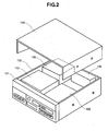
- FIG. 2 attached herewith shows an example of the entire structure of an electronic apparatus having a liquid cooling system therein, according to one embodiment of the present invention.
- the present invention is applied into amain part or portion of a personal computer, such as, of being so-called the desktop type, for example.
- the main portion of the desktop type personal computer comprises a housing 100, which is formed from a metal plate into a cubic shape thereof, for example, and on a front panel portion 101 thereof are provided various kinds of switches; including an electric power switch and so on, and also indicator lamps, etc. Also, within an inside thereof is disposed a driver device 102, for driving various kinds of external information recording medium; such as, a floppy disk, a CD, and a DVD, etc., so that it positions an opening thereof on the front panel portion 101. Also, a reference numeral 103 in the figure depicts a memory portion provided within the housing 100 mentioned above, comprising a hard disk device, for example. And also, a reference numeral 104 in the figure depicts a cover to be put on the housing 100 mentioned above.
- an electronic circuit portion 105 having a liquid cooling system according to the present invention
- a reference numeral 106 in the figure depicts an electric power source portion for supplying from a commercial electric power source, a desired electric power to each of the portions, including, the driver device 102, the memory portion 103, and the electronic circuit portion 105 mentioned above.
- Fig. 1 attached herewith is shown the electronic circuit portion 105 of the electronic apparatus, the brief structure of which was explained in the above; i.e., within the desktop type personal computer, in particular, mainly around a heat receiving jacket 50 for mounting thereon a heat-generation element, such as, a CPU, as a main or principle structure thereof.
- a chip 200 of the CPU being such the heat-generation element as was mentioned, is mounted on a lower side surface of the heat-receiving jacket 50 mentioned above, being in contact with, directly, therefore it is not illustrated on the figure, herein.
- this electronic circuit portion 105 comprises the above-mentioned heat-receiving (or cooling) jacket 50 for mounting the CPU thereon, a radiator portion 60 for radiating heat generated from the CPU into an outside of the apparatus, a plural number (in the present example, two (2) pieces) of circulation pumps 71 and 72 for building up a redundant cooling system, and further flow passages are formed by connecting tubes (conduits) 81, 82..., each being made of a metal, or an elastic material, such as a rubber or the like, being covered with a metal film, etc., on the outer surface thereof, so as to prevent the liquid coolant inside from leaking outside, for communicating a liquid coolant (for example, a water, or a mixture of water with a so-called anti-freezing solution, such as, propylene glycol, at a predetermined ratio thereof) to each of those portions building up the heat cycle.
- a liquid coolant for example, a water, or a mixture of water with a so-called anti-freezing solution, such as,
- this heat-receiving (or cooling) jacket 50 is a plate-like member, being made of a metal having high heat conductivity, such as cupper or the like, and being formed with a cooling passage within an inside thereof, to communicate the liquid coolant into the passage thereof, thereby removing (moving) the heat generated from the CPU into the outside.
- Fig. 3 attached herewith shows the structure of the redundant cooling system, including therein the heat-receiving jacket 50 and the radiator 60 mentioned above, in the form of a block diagram.
- the radiator 60 mentioned above is connected to a first circulation pump P1 via the tube (or conduit) 81, and further, it is connected to a second circulation pump P2 via the tube (or conduit) 82.
- this second circulation pump P2 is connected to the heat-receiving jacket 50 mentioned above, via the tube (or conduit) 83, and thereafter is turned back to the radiator 60, again, via the tube (or conduit) 84, thereby building up a loop.
- the first circulation pump P1 (71) and the second circulation pump P2 (72) mentioned above are connected in a so-called series connection.
- tubes (or conduits) 85 and 86 connecting across an inlet and an outlet thereof, respectively, and further on each of the outlet (or discharge) sides thereof is connected a check valve 91 or 92, respectively, but the details of which will be explained later.
- the above-mentioned water or the water mixture with the anti-freezing solution circulates within the liquid circuit mentioned above, as the liquid coolant.
- the liquid pressure (p71) or (p72) of the coolant discharged from each of the pumps is larger than the liquid pressure (p85) or (p86) within the tube (or conduit) 85 or 86 building up the bypass passage thereof, and for this reason, a ball valve 911 or 921 is pushed down towards a seat 912 or 922 .
- the liquid coolant not passing through the bypass passage 85 or 86, but passes through the circulation pumps 71 and 72, thereby circulating within the cooling system.
- the each ball valve 911 or 921 is adjusted, so that it is nearly equal to the specific gravity of the liquid coolant, therefore starting the movement thereof even with a little pressure difference therebetween.
- the circulation pump 71 stops the function thereof, because of the reasons that an electric motor stops, forming a driving portion thereof (in this case, the motor M1 in the figure), or that a blade of the pump adheres, etc., for example, then almost of the liquid coolant flowing within the cooling system runs along with a route indicated by an arrow in Fig. 5 attached herewith, due to the function of the circulation pump 72 of the other-side.
- the liquid pressure (p72) of the coolant discharged from the second pump decreases down due to the stoppage of operation in the other-side circulation pump 72, and then the ball valve 921 comes away from the seat 922, thereby opening the bypass passage.
- the one-side circulation pump 71 still keeps the operation thereof, and the liquid pressure (p71) discharged from the first pump is larger than the liquid pressure (p85) of the coolant within the tube (or conduit) 85 building up the bypass passage thereof, therefore the ball valve 911 is pushed down to the seat 912; i.e., the bypass passage is closed.
- the liquid coolant passes through the one-side circulation pump 71, and thereafter it passes through the bypass passage 86, thereby circulating within the cooling system.
- an electronic apparatus can be provided, having the cooling system therein, being suitable to be applied in the personal computer, being so-called such the desktop type or the notebook type, as mentioned above, and/or the server, etc., being high in the cooling efficiency thereof, as well as, having redundancy therewith.
- bypass passage is provided for each of the circulation pumps, respectively, each being able to open when occurring a trouble due to the function of the check valve, in the embodiment mentioned in the above, however this is due to the fact that the circulation pump itself in trouble/stoppage comes to be a large resistance for the liquid coolant circulating within the cooling system, when the circulation pump is in trouble or stopped, so that the circulating liquid coolant is lowed down in flow rate thereof.
- the explanation was made only about the check valve of the structure using the ball valve therein, however it may have the structure other than that, as far as it can achieve the function mentioned above, but without limiting the structure only thereto.
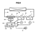
- FIG. 9 attached shows the circuit structure of the controller system in the redundant cooling system mentioned above, in the form of a block diagram. Namely, as shown in the figure, there are provided detectors (or sensors) 75 and 76 for the plural number of circulation pump; e.g. , the circulation pumps 71 and 72, respectively, in the present embodiment.
- each of the circulation pumps mentioned above is a flat centrifugal pump, in general, and as a driving source for rotationally driving thereof, also a flat type electric motor is applied, such as, a direct-current (DC) motor, for example; therefore, it is possible to detect the stoppage and/or the trouble of the circulation pump, through detection of a rotation velocity of the DC motor.
- DC direct-current
- a terminal for outputting a signal indicative of the rotation velocity thereof there is provided a signal indicative of the rotation velocity thereof, and it is also possible to use the output provided at that terminal, in such the case.
- the detection outputs of those detectors 75 and 76 are inputted through an interface (I/F) portion 201 to the CPU 200, which builds up a portion of the controller system.
- I/F interface
- various kinds of memories in the form of an exterior circuit thereof; such as, a RAM 202, ROM 203, to be used for calculation processing thereof, through a bus 204, however it is possible to build up those as a unit.
- an alarm lamp 77 is connected to the interface portion 201 mentioned above, for the purpose of warning the trouble caused in the circulation pump.
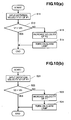
- the rotation number (i.e., the rotation velocity V1) of the above-mentioned first circulation pump (i.e., the pump P1) is inputted into, through the I/F portion 201 mentioned above (step S11).
- the rotation velocity V1 inputted is compared with a reference value (Vth), which was preset for determining the trouble of the pump, thereby determining on whether the pump P1 is in the trouble or not (step S12).
- this reference value (Vth) is set to be about 30% of the normal rotation velocity of the pump, for example.
- step S12 determines whether the pump P1 is not in the trouble (see “Yes” in the figure). If it is determined that the pump P1 is not in the trouble (see “Yes” in the figure), the process is ended. On the other hand, if it is determined that the pump P1 is in the trouble (see “No” in the figure), the other one of the circulation pumps, i.e., the second circulation pump 72 (the pump P2) rises up the rotation number (the rotation velocity V2) thereof (steps 13), and further the alarm lamp 77 is turned ON (step S14).
- the second circulation pump 72 rises up the rotation number (the rotation velocity V2) thereof (steps 13) thereof
- an increase of velocity in the step S13 mentioned above is obtained by increasing up the driving voltage thereof, in particular in the case where the DC motor is used as the driving source of the pump, as was mentioned above, thereby setting up the rotation velocity to be 1.5-2 times higher than the normal one.
- the rotation number (the rotation velocity V2) of the second circulation pump (the pump P2) mentioned above is inputted, through the I/F portion 201 mentioned above (step S21). Then, this rotation velocity V2 inputted is also compared with the reference value (Vth), which was preset in advance for determining the trouble of the pump, thereby determining on whether the pump 2 is in the trouble or not (step S22). Thereafter, as a result of the determination, if the pump P2 is not in the trouble (see “Yes” in the figure), the process is stopped.
- the other one of the circulation pumps i.e., the first circulation pump 71 (the pump P1) rises up the rotation number (i.e., the rotation velocity V1) thereof (step 23). Further, the alarm lamp 77 is turned ON (step S24). Further, also in this case, the rotation number (i.e., the rotation velocity V1) of the first circulation pump 71 (the pump P1) is increased up, to be 1.5-2 times higher than the normal one, in the step S23 mentioned above.
- the alarm lamp 77 as a means of warning generation of the trouble may be constructed with other means, in the place thereof, such as, a buzzer or a speaker, etc., for generating an alarming sound or voices of alarming thereof, or alternatively, the warning may be displayed on a display device not shown in the figure, which builds up the personal computer therewith.
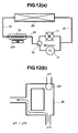
- FIG. 11(a) attached herewith shows the structure, according to other embodiment of the present invention, in the liquid cooling system, being provided within the electronic apparatus having a cooling system mentioned above.
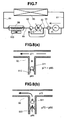
- the reference numerals same to the above also indicate the similar or same constituent elements in the embodiment mentioned above. Namely, as is clear from this figure, with this other embodiment, two (2) pieces of the circulation pumps 71 and 72 are connected, but in parallel with the flow passage of the liquid coolant, and a three-way valve 90 is attached at the side of a discharge openings of those pumps while omitting the bypass passages mentioned above, in the simple structure thereof .
- a reference numeral 901 in the figure depicts a ball valve provided within the three-way valve 90 mentioned above, in a manner of being movable.
- the ball valve 901 is also adjusted, to be nearly equal to that of the liquid coolant in the specific gravity thereof.
- Fig. 11(b) shows the condition of the three-way valve 90 in the case where no trouble occurs in the two (2) pieces of circulation pumps 71 and 72; thus, being under the normal operation thereof.
- the liquid pressure (p71) and (p72) are nearly equal to each other (p71. p72), being discharged from the each of the pumps, respectively.
- the ball valve 901 is located at a central portion, and the liquid coolant passes through those two (2) pieces of circulation pumps 71 and 72, as shown by arrows in the figures, thereby circulating within the cooling system.
- the liquid coolant keeps the circulation within the system, if one of those circulation pumps 71 and 72 stops, which are provided in the plural number thereof (i.e., two (2) pieces in the present embodiment), due to the function of the remaining (or other) circulation pump, therefore there is no chance that the liquid coolant stops the circulation thereof due to the trouble in the circulation pump, as was mentioned in the conventional arts.
- an electronic apparatus can be provided, having the cooling system therein, being suitable to be applied in the personal computer, being so-called such the desktop type or the notebook type, as mentioned above, and/or the server, etc., being high in the cooling efficiency thereof, as well as, having redundancy therewith. Also with the structure according to this other embodiment, it is obvious matter for the person skilled in the art, to apply the controller system therein, which is shown in Figs. 9 and 10 mentioned above.
- the tubes (or, the conduits) 82, 83..., connecting between the check valves 91 and 92 shown in Fig. 1 may be formed in one body together with the circulation pumps 71 and 72, respectively, or the entire of those may be integrated in one body.
- the tubes (or the conduits) provided on the three-way valve 90 and therebetween they may be made up into one body, together with the circulation pumps 71 and 72 mentioned above.
- those portions are made up into one body, it may be preferable in the structure, because of an easy attachment thereof in an assembling works.
- Fig. 14 shows the redundant cooling system, according to further other embodiment of the present invention, mainly around the heat-receiving jacket 50, on which the CPU is mounted, in the similar manner as in Fig. 1 mentioned above. Also in this embodiment, the reference numerals same to those shown in Fig. 1 mentioned above depict the same or similar constituent elements in the embodiment mentioned above.
- a coolant tank 200 is further provided between the radiator 60 mentioned above and the two (2) sets of circulation pumps 71 and 72, building up the redundant cooling system, for the purpose of storing or accumulating the liquid coolant circulating within the system; e.g., the water or the mixture of the water and the anti-freezing solution, such as, propylene glycol or the like, in an inside thereof.
- this coolant tank 200 is located horizontally, as is indicated by solid lines in the figure, or vertically, as is indicated by broken lines in the figure, for example, depending upon the restriction of the space within an inside thereof, when it is disposed within the inside of the housing 100 of the desktop-type personal computer shown in Fig. 2 in the above.
- the housing 100 itself see Fig. 2), installing the cooling system therein, is located horizontally or vertically, depending upon the condition thereof.
- the tank 200 within the housing of an electronic apparatus, such as 1U server, for example, having a low ceiling and only a narrow space defined therein, the tank 200 must be flat in the configuration thereof, thus, being large in the aspect ratio between the length and the breadth.
- the tank 200 having only one space defined therein is installed, directing the longer direction thereof horizontally, the liquid surface fluctuates largely within the tank 200 even if the housing swings a little bit, and upon the impulse of that moment, there is a possibility that babbles go out into the downstream, i.e., the side of the circulation pumps.
- this coolant tank 200 has the structure, as shown in Figs. 15(a) and 15(b) attached herewith, wherein the coolant storage space defined within the inside thereof is divided into a plural number of spaces (for example, three (3) spaces SP1, SP2 and SP3, in the present embodiment), with forming labylinth by combining partition walls 201, 202, 203 and 204, each having about "L"-like cross-section shape.
- a reference numeral 205 in the figure indicates an inlet for the liquid coolant flowing into from the radiator 60 mentioned above, and 206 an outlet for the liquid coolant flowing out into the circulation pump mentioned above (in more details, the first pump 71).
- reference numerals 206 and 207 indicate portions of the partition walls 202 and 204 having the "L"-like cross-section; thus, where each opening portion is formed at the position in vicinity of an outer periphery of the tank.
- an air contained within the tank 200 passes through the opening portions 206 and 207, back to the condition thereof, being close to the original one, as shown in Figs. 15(a) and 15(b) in the above.
- the air inside passes through the opening portions 206 and 207, and moves swiftly into the condition shown in Fig. 15(b).
- the liquid cooling system having the structure suitable to be applied in such the personal computer, being called by the desktop-type or the notebook-type, and also the server, etc., being high in the cooling efficiency, and also having redundancy, as well as, an electronic apparatus having such the system therein.
Landscapes
- Engineering & Computer Science (AREA)
- Theoretical Computer Science (AREA)
- Physics & Mathematics (AREA)
- General Engineering & Computer Science (AREA)
- Human Computer Interaction (AREA)
- General Physics & Mathematics (AREA)
- Computer Hardware Design (AREA)
- Thermal Sciences (AREA)
- Microelectronics & Electronic Packaging (AREA)
- Cooling Or The Like Of Electrical Apparatus (AREA)
- Cooling Or The Like Of Semiconductors Or Solid State Devices (AREA)
Abstract
Description
Claims (9)
- An electronic apparatus, installing a semiconductor element (200) generating heat within an inside of a housing (100), thereby necessitating cooling for maintaining a normal operation thereof, and including a cooling system within the inside of said housing (100) or in a portion thereof, said cooling system comprising:a cooling jacket (50) being thermally connected to the semiconductor element (200), for transmitting heat generated therefrom into a liquid coolant flowing inside thereof;a radiator (60) for radiating the heat transmitted into the liquid coolant in said cooling jacket (50) into an outside of the apparatus; anda circulation pump (71, 72) for circulating said liquid coolant within a loop, including said cooling jacket (50) and said radiator (60) therein, wherein:said circulation pump (71, 72) is provided in a plural number thereof, and further including means for maintaining circulation of said liquid coolant, if one of said plural number of circulation pumps (71, 72) stops function thereof, through the others thereof.
- Electronic apparatus according to claim 1,
characterized in that two (2) sets of said circulation pumps (71, 72) are connected in series, and said liquid coolant circulation maintaining means comprises flow passages, being connected to said two (2) sets of circulation pumps (70), respectively, and check valves (91, 92), each being attached to a portion of each of the flow passages. - Electronic apparatus according to claim 1 or 2, characterized in that two (2) sets of said circulation pumps (71, 72) are connected in parallel, and said liquid coolant circulation maintaining means comprises a three-way valve (90) connected to said two (2) sets of circulation pumps (71, 72).
- Electronic apparatus according to any of claims 1 to 3, characterized in that said liquid coolant circulation maintaining means further comprises a means for increasing rotation velocity of said other circulation pumps when the one of said plural number of circulation pumps (71, 72) stop the function thereof.
- Electronic apparatus according to claim 4, characterized in that said rotation velocity increase means for the circulation pumps (71, 72) is built up with using a portion of said semiconductor element (200).
- Electronic apparatus according to claim 4 or 5, characterized in that said liquid coolant circulation maintaining means further comprises an alarm means for warning of stoppage of said function when the one of said plural number of circulation pumps stop the function thereof.
- Electronic apparatus according to any of claims 1 to 6, characterized in that said liquid cooling system further comprises a tank (200) being able to supply the liquid coolant therefrom, always in spite of dispositional direction thereof.
- A cooling system, for cooling a semiconductor element generating heat therefrom, comprising:a cooling jacket (50) being thermally connected to a semiconductor element (200), for transmitting heat generated therefrom into a liquid coolant flowing inside thereof;a radiator (60) for radiating the heat transmitted into the liquid coolant in said cooling jacket (50) into an outside of the apparatus; anda circulation pump (71, 72) for circulating said liquid coolant within a loop, including said cooling jacket (50) and said radiator (60) therein, wherein:said circulation pump (71, 72) is provided in a plural number thereof, and further including means for maintaining circulation of said liquid coolant, if one of said plural number of circulation pumps (71, 72) stops function thereof, through the others thereof.
- A cooling system, for cooling a semiconductor element (200) generating heat therefrom, comprising:a cooling jacket (50) being thermally connected to a semiconductor element (200), for transmitting heat generated therefrom into a liquid coolant flowing inside thereof;a radiator (60) for radiating the heat transmitted into the liquid coolant in said cooling jacket (50) into an outside of the apparatus; anda circulation pump (71, 72) for circulating said liquid coolant within a loop, including said cooling jacket (50) and said radiator (60) therein, and further comprising: -a coolant tank (200), being divided in an inside thereof into a plural number of spaces, in an upstream side of said circulation pump (71,72).
Applications Claiming Priority (2)
| Application Number | Priority Date | Filing Date | Title |
|---|---|---|---|
| JP2004038358A JP2005228237A (en) | 2004-02-16 | 2004-02-16 | Liquid cooling system and electronic apparatus equipped with the same |
| JP2004038358 | 2004-02-16 |
Publications (2)
| Publication Number | Publication Date |
|---|---|
| EP1571532A2 true EP1571532A2 (en) | 2005-09-07 |
| EP1571532A3 EP1571532A3 (en) | 2006-10-25 |
Family
ID=34747405
Family Applications (1)
| Application Number | Title | Priority Date | Filing Date |
|---|---|---|---|
| EP04005450A Withdrawn EP1571532A3 (en) | 2004-02-16 | 2004-03-08 | Redundant liquid cooling system and electronic apparatus having the same therein |
Country Status (6)
| Country | Link |
|---|---|
| US (1) | US7149084B2 (en) |
| EP (1) | EP1571532A3 (en) |
| JP (1) | JP2005228237A (en) |
| KR (1) | KR100607004B1 (en) |
| CN (1) | CN100343782C (en) |
| TW (1) | TWI239442B (en) |
Cited By (3)
| Publication number | Priority date | Publication date | Assignee | Title |
|---|---|---|---|---|
| GB2413709B (en) * | 2004-04-29 | 2007-10-31 | Hewlett Packard Development Co | Liquid cooling system and pump assembly |
| WO2008014578A1 (en) * | 2006-08-03 | 2008-02-07 | Carlos Wagner De Souza | System of cooling for data center and similar |
| EP3496522A3 (en) * | 2017-12-07 | 2019-08-14 | Hewlett-Packard Enterprise Development LP | Chassis cooling |
Families Citing this family (110)
| Publication number | Priority date | Publication date | Assignee | Title |
|---|---|---|---|---|
| JP4561632B2 (en) * | 2003-06-27 | 2010-10-13 | 日本電気株式会社 | Electronic equipment cooling device |
| US7508672B2 (en) * | 2003-09-10 | 2009-03-24 | Qnx Cooling Systems Inc. | Cooling system |
| JP2005129812A (en) * | 2003-10-27 | 2005-05-19 | Hitachi Ltd | Liquid cooling system |
| JP4272503B2 (en) * | 2003-12-17 | 2009-06-03 | 株式会社日立製作所 | Liquid cooling system |
| US20050138944A1 (en) * | 2003-12-30 | 2005-06-30 | Gwin Paul J. | Liquid cooling system |
| US7280358B2 (en) * | 2004-04-19 | 2007-10-09 | Hewlett-Packard Development Company, L.P. | Liquid loop with multiple heat exchangers for efficient space utilization |
| JP2005317798A (en) * | 2004-04-28 | 2005-11-10 | Toshiba Corp | Electronics |
| JP2005317796A (en) * | 2004-04-28 | 2005-11-10 | Toshiba Corp | Pump, cooling device and electronic equipment |
| JP4234635B2 (en) * | 2004-04-28 | 2009-03-04 | 株式会社東芝 | Electronics |
| JP2005315158A (en) * | 2004-04-28 | 2005-11-10 | Toshiba Corp | Pumps, cooling devices, and electronics |
| US7203063B2 (en) * | 2004-05-21 | 2007-04-10 | Hewlett-Packard Development Company, L.P. | Small form factor liquid loop cooling system |
| JP4343032B2 (en) * | 2004-05-31 | 2009-10-14 | 株式会社東芝 | Cooling structure and projection type image display device |
| JP2005344562A (en) * | 2004-06-01 | 2005-12-15 | Toshiba Corp | Electronic device having pump, cooling device and cooling device |
| US7259961B2 (en) * | 2004-06-24 | 2007-08-21 | Intel Corporation | Reconfigurable airflow director for modular blade chassis |
| US7420804B2 (en) * | 2004-06-30 | 2008-09-02 | Intel Corporation | Liquid cooling system including hot-swappable components |
| US20060144566A1 (en) * | 2004-12-30 | 2006-07-06 | Jensen Kip B | System and method for cooling an integrated circuit device by electromagnetically pumping a fluid |
| US7599761B2 (en) * | 2005-01-19 | 2009-10-06 | Hewlett-Packard Development Company, L.P. | Cooling assist module |
| TWI257285B (en) * | 2005-04-11 | 2006-06-21 | Delta Electronics Inc | Heat-dissipating module of electronic device |
| US20070047203A1 (en) * | 2005-08-31 | 2007-03-01 | Wen-Han Chen | Integral liquid cooling computer housing |
| TWM284951U (en) * | 2005-09-21 | 2006-01-01 | Yen Sun Technology Corp | Heat dissipating device for an electronic device |
| US7353862B2 (en) * | 2005-10-03 | 2008-04-08 | Fu Zhun Precision Industry (Shenzhen) Co., Ltd. | Liquid cooling device |
| US7548421B2 (en) * | 2005-10-25 | 2009-06-16 | Hewlett-Packard Development Company, L.P. | Impingement cooling of components in an electronic system |
| US8051897B2 (en) * | 2005-11-30 | 2011-11-08 | International Business Machines Corporation | Redundant assembly for a liquid and air cooled module |
| US20070125523A1 (en) * | 2005-12-01 | 2007-06-07 | Bhatti Mohinder S | Low profile liquid cooled server heat sink |
| DE102006022464B4 (en) * | 2006-05-13 | 2008-09-25 | Khs Ag | Method and device for the controlled foaming of a product introduced in bottles or the like |
| JP5133531B2 (en) * | 2006-07-25 | 2013-01-30 | 富士通株式会社 | Heat exchanger for liquid cooling unit, liquid cooling unit and electronic equipment |
| JP4842040B2 (en) | 2006-07-25 | 2011-12-21 | 富士通株式会社 | Electronics |
| JP5283836B2 (en) | 2006-07-25 | 2013-09-04 | 富士通株式会社 | Heat receiver and liquid cooling unit for liquid cooling unit and electronic device |
| JP5148079B2 (en) * | 2006-07-25 | 2013-02-20 | 富士通株式会社 | Heat exchanger for liquid cooling unit, liquid cooling unit and electronic equipment |
| JP2008027374A (en) | 2006-07-25 | 2008-02-07 | Fujitsu Ltd | Heat receiver and liquid cooling unit for liquid cooling unit and electronic device |
| JP4781929B2 (en) * | 2006-07-25 | 2011-09-28 | 富士通株式会社 | Electronics |
| JP2008027370A (en) * | 2006-07-25 | 2008-02-07 | Fujitsu Ltd | Electronics |
| US7542290B2 (en) * | 2006-09-26 | 2009-06-02 | Hewlett-Packard Development Company, L.P. | Computer device cooling system |
| KR100851810B1 (en) | 2006-11-16 | 2008-08-13 | 한국생산기술연구원 | Chiller for water-cooled electronics cooling device using PCM |
| US20080121384A1 (en) * | 2006-11-29 | 2008-05-29 | Po-Yung Tseng | Liquid cooled heat dissipator |
| US7372698B1 (en) * | 2006-12-21 | 2008-05-13 | Isothermal Systems Research, Inc. | Electronics equipment heat exchanger system |
| TW200847901A (en) * | 2007-05-18 | 2008-12-01 | Cooler Master Co Ltd | Water-cooling heat-dissipation system |
| US9496200B2 (en) | 2011-07-27 | 2016-11-15 | Coolit Systems, Inc. | Modular heat-transfer systems |
| US9453691B2 (en) | 2007-08-09 | 2016-09-27 | Coolit Systems, Inc. | Fluid heat exchange systems |
| JP5009085B2 (en) * | 2007-08-09 | 2012-08-22 | 新光電気工業株式会社 | Semiconductor device |
| US8746330B2 (en) | 2007-08-09 | 2014-06-10 | Coolit Systems Inc. | Fluid heat exchanger configured to provide a split flow |
| US9943014B2 (en) | 2013-03-15 | 2018-04-10 | Coolit Systems, Inc. | Manifolded heat exchangers and related systems |
| DE102008025951B4 (en) * | 2008-05-30 | 2010-10-28 | Airbus Deutschland Gmbh | Cooling an electronic device in an aircraft by a case-wise single-phase or two-phase cooling |
| US20100032141A1 (en) * | 2008-08-08 | 2010-02-11 | Sun Microsystems, Inc. | cooling system utilizing carbon nanotubes for cooling of electrical systems |
| US9238398B2 (en) * | 2008-09-25 | 2016-01-19 | B/E Aerospace, Inc. | Refrigeration systems and methods for connection with a vehicle's liquid cooling system |
| JP5412815B2 (en) * | 2008-12-04 | 2014-02-12 | 富士通株式会社 | Cooling jacket, cooling unit, cooling system and electronic equipment |
| CN102056459A (en) * | 2009-10-30 | 2011-05-11 | 鸿富锦精密工业(深圳)有限公司 | Liquid-cooling heat radiating device |
| US20110253347A1 (en) | 2010-04-19 | 2011-10-20 | Steve Harrington | Vacuum Pumped Liquid Cooling System for Computers |
| CN101789413B (en) * | 2010-04-19 | 2011-05-04 | 山东大学 | Mixed small-channel cooler |
| US9010141B2 (en) | 2010-04-19 | 2015-04-21 | Chilldyne, Inc. | Computer cooling system and method of use |
| US8472182B2 (en) | 2010-07-28 | 2013-06-25 | International Business Machines Corporation | Apparatus and method for facilitating dissipation of heat from a liquid-cooled electronics rack |
| US8248801B2 (en) | 2010-07-28 | 2012-08-21 | International Business Machines Corporation | Thermoelectric-enhanced, liquid-cooling apparatus and method for facilitating dissipation of heat |
| TWI399636B (en) * | 2010-09-08 | 2013-06-21 | Chi Lin Technology Co Ltd | Electronic device with cooling system |
| JP2012160629A (en) * | 2011-02-02 | 2012-08-23 | Seiko Epson Corp | Heat exchanger and electronic device |
| FR2972894B1 (en) * | 2011-03-14 | 2013-04-26 | Converteam Technology Ltd | ENERGY CONVERTING DEVICE, IN PARTICULAR FOR A SUB-MARINE COMPRESSION AND PUMPING STATION, WITH IMPROVED COOLING MEANS |
| JP5812258B2 (en) * | 2011-05-26 | 2015-11-11 | 栗田工業株式会社 | Liquid heater |
| US10365667B2 (en) | 2011-08-11 | 2019-07-30 | Coolit Systems, Inc. | Flow-path controllers and related systems |
| JP5970827B2 (en) * | 2012-01-18 | 2016-08-17 | アイシン精機株式会社 | Pump control system |
| JP5982911B2 (en) | 2012-03-19 | 2016-08-31 | 富士通株式会社 | Pump, pump system, pump control method and cooling system |
| JP2014053467A (en) * | 2012-09-07 | 2014-03-20 | Fujitsu Ltd | Cooling system |
| JP6003423B2 (en) * | 2012-09-07 | 2016-10-05 | 富士通株式会社 | Cooling unit and electronic device |
| US20140069614A1 (en) * | 2012-09-13 | 2014-03-13 | Asia Vital Components Co., Ltd. | Heat dissipaion device and thermal module using same |
| TWI531795B (en) | 2013-03-15 | 2016-05-01 | 水冷系統公司 | Sensors, multiplexed communication techniques, and related systems |
| US12366870B2 (en) | 2013-03-15 | 2025-07-22 | Coolit Systems, Inc. | Flow-path controllers and related systems |
| CA2914797A1 (en) * | 2013-05-06 | 2014-11-13 | Green Revolution Cooling, Inc. | System and method of packaging computing resources for space and fire-resistance |
| CN104144592B (en) * | 2013-05-09 | 2016-12-07 | 鸿富锦精密工业(深圳)有限公司 | Cooling system and be provided with the Cabinet-type server of this cooling system |
| US8820351B1 (en) * | 2013-06-25 | 2014-09-02 | Chilldyne, Inc. | No drip hot swap connector and method of use |
| US9736967B2 (en) * | 2013-08-07 | 2017-08-15 | Abb S.P.A. | Cooling apparatus for an electrical or electronic device, and electrical or electronic device, in particular a circuit breaker, comprising such cooling apparatus |
| US9857809B2 (en) * | 2013-12-30 | 2018-01-02 | Intel Corporation | Fuzzy logic control of thermoelectric cooling in a processor |
| US10455726B2 (en) * | 2014-09-30 | 2019-10-22 | Hewlett Packard Enterprise Development Lp | Modular cooling |
| CN104699206A (en) * | 2015-03-25 | 2015-06-10 | 北京德能恒信科技有限公司 | Cooling cabinet of data center |
| JP2016200104A (en) * | 2015-04-14 | 2016-12-01 | 富士通株式会社 | Pump, cooling device, and electronic device |
| JP6424734B2 (en) * | 2015-05-20 | 2018-11-21 | 富士通株式会社 | Two-phase cooling system |
| JP6447731B2 (en) * | 2015-07-17 | 2019-01-09 | 富士通株式会社 | Heat transport device and electronic device |
| JP7403742B2 (en) * | 2015-12-29 | 2023-12-25 | ズターコア エルティーディー. | Vacuum-based thermal management system |
| JP2017145793A (en) | 2016-02-19 | 2017-08-24 | 富士通株式会社 | Cooling device and electronic equipment |
| US10136554B2 (en) * | 2017-03-31 | 2018-11-20 | International Business Machines Corporation | Passive two-phase cooling with forced cooling assist |
| CN110868967B (en) * | 2017-07-10 | 2024-10-29 | 奇跃公司 | Method and system for integrating electronic sensor with heat dissipation system |
| CN107529316A (en) * | 2017-07-26 | 2017-12-29 | 云南靖创液态金属热控技术研发有限公司 | A kind of liquid metal two-fluid heat abstractor and mobile phone shell |
| US11452243B2 (en) | 2017-10-12 | 2022-09-20 | Coolit Systems, Inc. | Cooling system, controllers and methods |
| JP6993546B2 (en) * | 2018-02-14 | 2022-01-13 | 日本電産サンキョー株式会社 | Cooling system |
| JP7181443B2 (en) | 2018-02-14 | 2022-12-01 | 日本電産サンキョー株式会社 | Cooling system |
| AT520915B1 (en) * | 2018-09-04 | 2019-07-15 | Claus Hinterecker | Device for cooling high-performance computers or circuits with temperature control |
| US11152283B2 (en) | 2018-11-15 | 2021-10-19 | Hewlett Packard Enterprise Development Lp | Rack and row-scale cooling |
| US10746084B2 (en) * | 2018-12-13 | 2020-08-18 | General Electric Company | Liquid driven thermal module and thermal management system |
| CN109857227A (en) * | 2018-12-28 | 2019-06-07 | 曙光节能技术(北京)股份有限公司 | The liquid cooling system of server |
| US11662037B2 (en) | 2019-01-18 | 2023-05-30 | Coolit Systems, Inc. | Fluid flow control valve for fluid flow systems, and methods |
| EP3703476B1 (en) | 2019-02-28 | 2022-07-20 | Ovh | Cooling arrangement having primary and secondary cooling devices for cooling an electronic device |
| US11473860B2 (en) | 2019-04-25 | 2022-10-18 | Coolit Systems, Inc. | Cooling module with leak detector and related systems |
| TWI708037B (en) * | 2019-08-19 | 2020-10-21 | 奇鋐科技股份有限公司 | Water-cooling pump structure with check valves and water-cooling module thereof |
| US11765864B2 (en) | 2019-08-26 | 2023-09-19 | Ovh | Cooling arrangement for a rack hosting electronic equipment and at least one fan |
| US10925187B1 (en) * | 2019-08-30 | 2021-02-16 | Dell Products, L.P. | Remote heat exchanger arm for direct contact liquid cooling for rack mounted equipment |
| WO2021078244A1 (en) * | 2019-10-24 | 2021-04-29 | 杭州三花微通道换热器有限公司 | Heat exchange system used for heat dissipation of electronic control component and computer host |
| US12200913B2 (en) * | 2020-02-21 | 2025-01-14 | Nvidia Corporation | Intelligent and integrated liquid-cooled rack for datacenters |
| US11395443B2 (en) | 2020-05-11 | 2022-07-19 | Coolit Systems, Inc. | Liquid pumping units, and related systems and methods |
| JP7693392B2 (en) * | 2020-07-22 | 2025-06-17 | ニデック株式会社 | Pumping equipment, cooling units and cooling systems |
| CN111818770A (en) * | 2020-07-28 | 2020-10-23 | 常州威图流体科技有限公司 | A liquid-cooled heat dissipation module, a liquid-cooled heat dissipation system and electronic equipment |
| US11306828B2 (en) * | 2020-07-31 | 2022-04-19 | Quanta Computer Inc. | Quick-connector valve for liquid cooling |
| JP7459722B2 (en) * | 2020-08-21 | 2024-04-02 | ニデック株式会社 | Liquid feeding device |
| EP4268276A1 (en) | 2020-12-23 | 2023-11-01 | Abaco Systems, Inc. | Cooling module for providing enhanced localized cooling of a heatsink |
| US11640190B2 (en) * | 2021-04-14 | 2023-05-02 | Dell Products L.P. | Liquid-assisted air cooling design with parallel cold plates and serial pumps |
| US11683910B2 (en) * | 2021-04-27 | 2023-06-20 | Quanta Computer Inc. | Hot plug redundant pump for cooling system |
| US11725886B2 (en) | 2021-05-20 | 2023-08-15 | Coolit Systems, Inc. | Modular fluid heat exchange systems |
| JP7703403B2 (en) * | 2021-09-01 | 2025-07-07 | ニデック株式会社 | Heat dissipation and cooling devices |
| US11950394B2 (en) | 2021-10-12 | 2024-04-02 | Ge Aviation Systems Llc | Liquid-cooled assembly and method |
| US12200914B2 (en) | 2022-01-24 | 2025-01-14 | Coolit Systems, Inc. | Smart components, systems and methods for transferring heat |
| JP2023111798A (en) * | 2022-01-31 | 2023-08-10 | ニデック株式会社 | Cooling system |
| US12439569B2 (en) * | 2022-06-13 | 2025-10-07 | Cooper-Standard Automotive, Inc. | Shift pump flow scheme |
| US12619291B2 (en) * | 2023-05-17 | 2026-05-05 | Quanta Computer Inc. | Hot plug redundant pump with electronically controlled valve |
| TWI851208B (en) * | 2023-05-17 | 2024-08-01 | 黃崇賢 | Dual-liquid pump liquid cooling row and liquid cooling heat dissipation device |
Family Cites Families (18)
| Publication number | Priority date | Publication date | Assignee | Title |
|---|---|---|---|---|
| JPH0680914B2 (en) * | 1989-02-06 | 1994-10-12 | 富士通株式会社 | tank |
| JP3329663B2 (en) * | 1996-06-21 | 2002-09-30 | 株式会社日立製作所 | Cooling device for electronic devices |
| US6234240B1 (en) * | 1999-07-01 | 2001-05-22 | Kioan Cheon | Fanless cooling system for computer |
| US6166907A (en) * | 1999-11-26 | 2000-12-26 | Chien; Chuan-Fu | CPU cooling system |
| CN2434454Y (en) * | 2000-07-18 | 2001-06-13 | 上海凯泉泵业(集团)有限公司 | Single-stage single-sucking vertical split centrifugal pump set |
| KR20020024752A (en) | 2000-09-26 | 2002-04-01 | 김거부 | Temperature control unit for non-stop operation in semiconductor fabricating apparatus and auto substitution operating method therefore |
| US6351381B1 (en) * | 2001-06-20 | 2002-02-26 | Thermal Corp. | Heat management system |
| US6711017B2 (en) * | 2001-07-17 | 2004-03-23 | Hitachi Kokusai Electric Inc. | Cooling apparatus for electronic unit |
| US6587343B2 (en) * | 2001-08-29 | 2003-07-01 | Sun Microsystems, Inc. | Water-cooled system and method for cooling electronic components |
| JP3636118B2 (en) * | 2001-09-04 | 2005-04-06 | 株式会社日立製作所 | Water cooling device for electronic equipment |
| US7024573B2 (en) * | 2002-02-05 | 2006-04-04 | Hewlett-Packard Development Company, L.P. | Method and apparatus for cooling heat generating components |
| JP3961844B2 (en) | 2002-02-08 | 2007-08-22 | 株式会社日立製作所 | Coolant tank |
| WO2003098415A1 (en) * | 2002-05-15 | 2003-11-27 | Matsushita Electric Industrial Co., Ltd. | A liquid cooling device for a notebook computer |
| JP3885679B2 (en) * | 2002-06-28 | 2007-02-21 | 株式会社日立製作所 | Electronics |
| US20040008483A1 (en) * | 2002-07-13 | 2004-01-15 | Kioan Cheon | Water cooling type cooling system for electronic device |
| US6807056B2 (en) * | 2002-09-24 | 2004-10-19 | Hitachi, Ltd. | Electronic equipment |
| TWI220468B (en) * | 2003-05-20 | 2004-08-21 | Micro Star Int Co Ltd | Computer system with a heat dissipation module having a plurality of pumps |
| US7508671B2 (en) * | 2003-10-10 | 2009-03-24 | Intel Corporation | Computer system having controlled cooling |
-
2004
- 2004-02-16 JP JP2004038358A patent/JP2005228237A/en active Pending
- 2004-02-26 TW TW093104963A patent/TWI239442B/en not_active IP Right Cessation
- 2004-03-05 US US10/792,718 patent/US7149084B2/en not_active Expired - Lifetime
- 2004-03-05 CN CNB2004100077724A patent/CN100343782C/en not_active Expired - Fee Related
- 2004-03-06 KR KR1020040015244A patent/KR100607004B1/en not_active Expired - Fee Related
- 2004-03-08 EP EP04005450A patent/EP1571532A3/en not_active Withdrawn
Cited By (5)
| Publication number | Priority date | Publication date | Assignee | Title |
|---|---|---|---|---|
| GB2413709B (en) * | 2004-04-29 | 2007-10-31 | Hewlett Packard Development Co | Liquid cooling system and pump assembly |
| US8430156B2 (en) | 2004-04-29 | 2013-04-30 | Hewlett-Packard Development Company, L.P. | Liquid loop with multiple pump assembly |
| WO2008014578A1 (en) * | 2006-08-03 | 2008-02-07 | Carlos Wagner De Souza | System of cooling for data center and similar |
| EP3496522A3 (en) * | 2017-12-07 | 2019-08-14 | Hewlett-Packard Enterprise Development LP | Chassis cooling |
| US10813253B2 (en) | 2017-12-07 | 2020-10-20 | Hewlett Packard Enterprise Development Lp | Chassis cooling |
Also Published As
| Publication number | Publication date |
|---|---|
| TWI239442B (en) | 2005-09-11 |
| KR100607004B1 (en) | 2006-08-01 |
| EP1571532A3 (en) | 2006-10-25 |
| KR20050081816A (en) | 2005-08-19 |
| JP2005228237A (en) | 2005-08-25 |
| CN1658120A (en) | 2005-08-24 |
| US20050180105A1 (en) | 2005-08-18 |
| US7149084B2 (en) | 2006-12-12 |
| TW200528964A (en) | 2005-09-01 |
| CN100343782C (en) | 2007-10-17 |
Similar Documents
| Publication | Publication Date | Title |
|---|---|---|
| US7149084B2 (en) | Redundant liquid cooling system and electronic apparatus having the same therein | |
| US6809927B2 (en) | Liquid circulation cooling system for electronic apparatus | |
| US8016023B2 (en) | Method and an apparatus for cooling a computer | |
| JP3594900B2 (en) | Display integrated computer | |
| US20050180107A1 (en) | Electronic apparatus having liquid cooling system therein | |
| US20070089859A1 (en) | Electronic apparatus and cooling module | |
| EP1571533A2 (en) | Liquid cooling system, and electronic apparatus having the same therein | |
| KR100465088B1 (en) | The water cooling system for electronic device | |
| CN109933175A (en) | A kind of heat dissipation detection method, device and electronic equipment | |
| EP1708263B1 (en) | Cooling jacket | |
| JP2003209210A (en) | Electronic equipment | |
| JP2006234255A (en) | RADIATOR AND LIQUID COOLING SYSTEM HAVING THE RADIATOR | |
| JP4258292B2 (en) | Cooling system | |
| CN120103938A (en) | Combined cooling system and server | |
| JP2005190091A (en) | COOLING DEVICE AND ELECTRONIC DEVICE HAVING THE SAME | |
| CN109960382A (en) | Heat dissipation device capable of zoning heat dissipation and motherboard with heat dissipation device | |
| JP2003022148A (en) | Liquid cooling system for notebook PC | |
| US20070133170A1 (en) | Self-protection device of water-cooled dissipation system for computer | |
| JP2001132623A (en) | Pumping equipment | |
| JP4506483B2 (en) | Liquid cooling system | |
| CN211090361U (en) | Heat radiator | |
| JP2006250395A (en) | COOLING DEVICE AND ELECTRONIC DEVICE HAVING THE SAME | |
| CN223599941U (en) | An alarm device to prevent monitoring system crashes | |
| TW396264B (en) | Icemaker control device for an electric refrigerator of a type employing a thermoelectric module | |
| CN113721413A (en) | Laser projection system and heat dissipation device |
Legal Events
| Date | Code | Title | Description |
|---|---|---|---|
| PUAI | Public reference made under article 153(3) epc to a published international application that has entered the european phase |
Free format text: ORIGINAL CODE: 0009012 |
|
| AK | Designated contracting states |
Kind code of ref document: A2 Designated state(s): AT BE BG CH CY CZ DE DK EE ES FI FR GB GR HU IE IT LI LU MC NL PL PT RO SE SI SK TR |
|
| AX | Request for extension of the european patent |
Extension state: AL LT LV MK |
|
| PUAL | Search report despatched |
Free format text: ORIGINAL CODE: 0009013 |
|
| AK | Designated contracting states |
Kind code of ref document: A3 Designated state(s): AT BE BG CH CY CZ DE DK EE ES FI FR GB GR HU IE IT LI LU MC NL PL PT RO SE SI SK TR |
|
| AX | Request for extension of the european patent |
Extension state: AL LT LV MK |
|
| 17P | Request for examination filed |
Effective date: 20070425 |
|
| AKX | Designation fees paid |
Designated state(s): DE |
|
| 17Q | First examination report despatched |
Effective date: 20070907 |
|
| RAP1 | Party data changed (applicant data changed or rights of an application transferred) |
Owner name: HITACHI, LTD. |
|
| RAP1 | Party data changed (applicant data changed or rights of an application transferred) |
Owner name: HITACHI CONSUMER ELECTRONICS CO., LTD. |
|
| RAP1 | Party data changed (applicant data changed or rights of an application transferred) |
Owner name: HITACHI MAXELL, LTD. |
|
| STAA | Information on the status of an ep patent application or granted ep patent |
Free format text: STATUS: THE APPLICATION IS DEEMED TO BE WITHDRAWN |
|
| 18D | Application deemed to be withdrawn |
Effective date: 20160705 |