EP1571375A2 - Verfahren und Vorrichtung zur Bestimmung der Übersetzung des Getriebes - Google Patents
Verfahren und Vorrichtung zur Bestimmung der Übersetzung des Getriebes Download PDFInfo
- Publication number
- EP1571375A2 EP1571375A2 EP05101199A EP05101199A EP1571375A2 EP 1571375 A2 EP1571375 A2 EP 1571375A2 EP 05101199 A EP05101199 A EP 05101199A EP 05101199 A EP05101199 A EP 05101199A EP 1571375 A2 EP1571375 A2 EP 1571375A2
- Authority
- EP
- European Patent Office
- Prior art keywords
- speed
- gear
- rotor
- gear ratio
- gearbox
- Prior art date
- Legal status (The legal status is an assumption and is not a legal conclusion. Google has not performed a legal analysis and makes no representation as to the accuracy of the status listed.)
- Granted
Links
- 238000000034 method Methods 0.000 title claims abstract description 57
- 230000008569 process Effects 0.000 claims abstract description 53
- 238000004364 calculation method Methods 0.000 claims description 23
- 238000012545 processing Methods 0.000 claims description 6
- 238000003306 harvesting Methods 0.000 claims description 4
- 238000006073 displacement reaction Methods 0.000 description 7
- 230000001133 acceleration Effects 0.000 description 6
- 230000004044 response Effects 0.000 description 5
- 238000004891 communication Methods 0.000 description 4
- 238000013461 design Methods 0.000 description 4
- 238000013178 mathematical model Methods 0.000 description 4
- 241000239290 Araneae Species 0.000 description 3
- 230000008878 coupling Effects 0.000 description 3
- 238000010168 coupling process Methods 0.000 description 3
- 238000005859 coupling reaction Methods 0.000 description 3
- 239000012530 fluid Substances 0.000 description 3
- 230000002706 hydrostatic effect Effects 0.000 description 3
- 238000012360 testing method Methods 0.000 description 3
- 239000012773 agricultural material Substances 0.000 description 2
- 238000010586 diagram Methods 0.000 description 2
- 238000012986 modification Methods 0.000 description 2
- 230000004048 modification Effects 0.000 description 2
- 230000007935 neutral effect Effects 0.000 description 2
- 230000035939 shock Effects 0.000 description 2
- 230000005355 Hall effect Effects 0.000 description 1
- 244000046052 Phaseolus vulgaris Species 0.000 description 1
- 235000010627 Phaseolus vulgaris Nutrition 0.000 description 1
- 240000008042 Zea mays Species 0.000 description 1
- 235000005824 Zea mays ssp. parviglumis Nutrition 0.000 description 1
- 235000002017 Zea mays subsp mays Nutrition 0.000 description 1
- 230000008901 benefit Effects 0.000 description 1
- 230000008859 change Effects 0.000 description 1
- 230000009194 climbing Effects 0.000 description 1
- 238000002485 combustion reaction Methods 0.000 description 1
- 230000001143 conditioned effect Effects 0.000 description 1
- 238000010276 construction Methods 0.000 description 1
- 235000005822 corn Nutrition 0.000 description 1
- 230000003111 delayed effect Effects 0.000 description 1
- 230000006870 function Effects 0.000 description 1
- 230000001939 inductive effect Effects 0.000 description 1
- 230000003993 interaction Effects 0.000 description 1
- 238000012544 monitoring process Methods 0.000 description 1
- 238000001208 nuclear magnetic resonance pulse sequence Methods 0.000 description 1
- 230000001151 other effect Effects 0.000 description 1
- 235000021251 pulses Nutrition 0.000 description 1
- 238000009987 spinning Methods 0.000 description 1
- 238000006467 substitution reaction Methods 0.000 description 1
- 230000000153 supplemental effect Effects 0.000 description 1
Images



Classifications
-
- F—MECHANICAL ENGINEERING; LIGHTING; HEATING; WEAPONS; BLASTING
- F16—ENGINEERING ELEMENTS AND UNITS; GENERAL MEASURES FOR PRODUCING AND MAINTAINING EFFECTIVE FUNCTIONING OF MACHINES OR INSTALLATIONS; THERMAL INSULATION IN GENERAL
- F16H—GEARING
- F16H59/00—Control inputs to control units of change-speed- or reversing-gearings for conveying rotary motion
- F16H59/68—Inputs being a function of gearing status
- F16H59/70—Inputs being a function of gearing status dependent on the ratio established
-
- F—MECHANICAL ENGINEERING; LIGHTING; HEATING; WEAPONS; BLASTING
- F16—ENGINEERING ELEMENTS AND UNITS; GENERAL MEASURES FOR PRODUCING AND MAINTAINING EFFECTIVE FUNCTIONING OF MACHINES OR INSTALLATIONS; THERMAL INSULATION IN GENERAL
- F16H—GEARING
- F16H59/00—Control inputs to control units of change-speed- or reversing-gearings for conveying rotary motion
- F16H59/68—Inputs being a function of gearing status
- F16H59/70—Inputs being a function of gearing status dependent on the ratio established
- F16H2059/706—Monitoring gear ratio in stepped transmissions, e.g. by calculating the ratio from input and output speed
Definitions
- the invention relates to work vehicles such as agricultural combines. More particularly, it relates to work vehicles having gearboxes without a gear select sensor. Even more particularly, it relates to such vehicles having electronic control systems configured to determine gear ratios.
- Work vehicles such as agricultural combines monitor a variety of drive parameters. They have a variety of sensors responsive to pressures, speeds and positions of the various components that comprise the drive system.
- a sensor may directly indicate the gear ratio or gear range of a gearbox in the drive system.
- Other sensors may measure different parameters, such as hydraulic pressure, rotational speed, and other parameters.
- system parameters such as gear ratios may not be sensed directly, but may be determined by combining sensor data and knowledge of the mathematical system model to calculate or otherwise determine these system parameters.
- a gear ratio is determined by an electronic controller coupled to a motor speed sensor and a rotor speed sensor.
- a gearbox input speed the motor
- a gearbox output speed the rotor
- a process for determining whether a gearbox that drives a rotor in a work vehicle is engaged in at least a first gear ratio or a second gear ratio, said process comprising the step of determining from a calculation which of the first and second gear ratios said gearbox is engaged, characterised in that said process further comprises:
- a work vehicle comprising a rotor, a multiple gear ratio gearbox, drivingly connected to said rotor; and an electronic control system for determining whether said gearbox is engaged in at least a first gear ratio or a second gear ratio, said control system comprising at least one microcontroller configured for determining from a calculation which of the first and second gear ratios the gearbox is engaged; characterised in that said at least one microcontroller is further configured to:
- a work vehicle is illustrated, here shown as an agricultural combine 100.
- the work vehicle has a chassis 102 on which an engine 104 is mounted.
- a drive system 106 is coupled to and driven by engine 104 to rotate rotor 118.
- An electronic control system 108 is coupled to the engine and the drive system to monitor various sensors, to control the engine and to control the drive system.
- the engine 104 is preferably an internal combustion engine, such as a multi-cylinder gasoline or diesel engine.
- the drive system 106 includes a hydraulic pump 110 that is coupled to and driven by the engine, a hydraulic motor 112 that is fluidly coupled to and driven by pump 110, a gear train coupling engine 104 to the pump, a gear train coupling engine 104 to a planetary gear arrangement, the planetary gear arrangement 114 ( Figure 2) itself, and a gearbox 116 ( Figure 2) that drives the combine rotor 118.
- Rotor 118 rotates with respect to chassis 102 and threshes agricultural material, such as corn stalks.
- a header 120 is attached to the front of the combine to cut and gather the agricultural material from the field and direct it into the rotor, via the feeder 124, which receives and threshes it.
- a plurality of wheels 122 are coupled to the chassis to engage the ground and support the combine as it travels over the ground.
- One or more motors may be coupled to the wheels to drive the wheels in rotation, thereby driving the combine over the ground.
- FIG. 2 illustrates construction details of the work vehicle (and particularly the drive system 106) in a schematic form.
- Engine 104 has an output shaft 200 to which spur gear 202 is fixed.
- Gear 202 drives spur gear 204.
- Spur gear 204 is fixed to shaft 206, which is the input shaft to hydraulic pump 110.
- Hydraulic pump 110 is a variable displacement pump in which the specific output can be varied under electrical control.
- pump 110 has internal actuators to vary the displacement of the pump in response to an electrical signal.
- Controller 234 applies the signal to pump 110 over electrical control lines 209.
- Gear 202 also meshes with and drives spur gear 210, which is coupled to and drives the auger and header (not shown).
- Spur gear 210 in turn, meshes with and drives spur gear 212.
- Spur gear 212 in turn, is coupled to and drives the input shaft of engine-to-ring clutch 214.
- Engine-to-ring clutch 214 is a hydraulically actuated multi-plate clutch that couples gear 212 (and hence engine 104) to ring gear 216 of planetary gear arrangement 114.
- clutch 214 When clutch 214 is engaged, engine 104 is coupled to and drives ring gear 216.
- clutch 214 When clutch 214 is disengaged, engine 104 is disconnected from ring gear 216.
- a second clutch 220 (a ring-to-frame clutch) is coupled to and between ring gear 216 and the frame or chassis 102 (indicated by the ground symbol) to fix the ring gear with respect to the chassis or frame of the vehicle.
- clutch 220 When clutch 220 is engaged, ring gear 216 is fixed and cannot rotate.
- Pump 110 is hydraulically connected to motor 112 by hydraulic conduits 222. These conduits conduct fluid to and from motor 112 to form a closed loop hydraulic (hydrostatic) drive circuit.
- Motor 112 is coupled to and drives sun gear 224 of planetary gear arrangement 114.
- Sun gear 224 drives planet gears 226, which drive planetary gear carrier 228.
- Gearbox 116 is a multi-speed gearbox having a neutral and three manually selectable gear ratios with an input shaft 230 and an output shaft coupled to rotor 118.
- Input shaft 230 of gearbox 116 is fixed to and rotates together with planetary gear carrier 228.
- the output shaft of multi-speed gearbox 116 is coupled to and drives rotor 118.
- power from engine 104 to rotor 118 can follow one or both of two parallel paths.
- the first path is from engine 104, through the gearing, through clutch 214, through ring gear 216, through planet gears 226 into shaft 230.
- the second parallel path is from engine 104, through pump 110, through motor 112, through sun gear 224, through the planet gears 226 and into shaft 230.
- Engine 104 operates most efficiently at a set and predetermined rpm, yet the rotor cannot be operated at a set, predetermined speed, but must be variable over some range or ranges of speed to harvest the several types of crops it is intended and designed to do.
- the planetary gear arrangement permits power through both paths to be applied to the rotor.
- the motor drives the sun gear
- the engine drives the ring gear
- the planetary gear carrier receives power from both and applies that combined power to the rotor through gearbox 116.
- the electronic control system 108 including three digital electronic controllers and their associated sensors, controls the operation of the foregoing machine elements.
- System 108 includes a first digital electronic controller 234, a second digital electronic controller 236 and a third digital electronic controller 238 that are coupled together over a communications network, here shown as a CAN bus 240 in accordance with the SAE J1939 communications standard.
- a communications network here shown as a CAN bus 240 in accordance with the SAE J1939 communications standard.
- Each controller 234, 236, and 238 are similarly constructed, and include a microprocessor 242, a read-only memory (ROM) 244, a random access memory (RAM) 246 and an input/output (I/O) circuit 248.
- the ROM stores a control program that controls the operation of the controller.
- the RAM is temporary storage space for numeric values used in computation, and the I/O circuit handles external communications including communications with the sensors and the other controllers on the CAN bus 240.
- Each of these circuits is connected using a data/address/control bus of standard design, which is not shown.
- the first digital controller 234 is connected to two speed sensors, a rotor speed sensor 252, and a motor speed sensor 254. These sensors are respectively coupled to rotor 118 and motor 112 to sense the rotational speeds of these devices and transmit a signal indicative of those speeds to the first digital controller 234.
- the speed sensors in the present system preferably generate a series or stream of pulses as the rotor and motor turn.
- Common sensor arrangements that generate such pulse sequences include conditioned alternator signals, Hall Effect devices, and inductive pickups that sense the passage of slotted disks or gear teeth mounted on the shafts of the engine, rotor and motor, for example.
- the first digital controller 234 is also connected to and controls three other devices: pump 110, engine-to-ring clutch 214 and ring-to-frame clutch 220.
- Controller 234 generates and transmits a signal indicative of a desired specific displacement to pump 110. Pump 110 responsively changes its specific displacement to match the signal. In a similar fashion, controller 234 generates and transmits a clutch-engaging or clutch-disengaging signal to electrical solenoid valves (not shown) that conduct hydraulic fluid to and from the two clutches 214 and 220. The clutches responsively engage and disengage.
- the I/O circuit of second digital controller 236 is connected to an engine speed sensor 256 and to operator input device 258.
- Engine speed sensor 256 generates a signal indicative of the engine speed.
- the operator input device is preferably a switch responsive to operator manipulation that generates two separate signals, an "increase speed” signal and a “decrease speed” signal.
- Controller 236 is also connected to controller 234 and controller 238 via the CAN bus 240.
- controller 238 is a display controller. It is constructed the same as controller 234 and 236, but is dedicated to displaying data generated by the operator or the other controllers. This capability is provided by its own internal control program stored in its ROM memory. It also includes a display device such as an LCD or electroluminescent display.
- Controllers 234, 236, and 238 include internal digital control programs that control their operation. These programs are stored in the ROM memory of each controller. The programmed operation of each controller is discussed below.
- controller 238 displays several data indicative of the vehicle's status. The first of these, the rotor speed, indicates the speed of the rotor. Controller 234 generates the rotor speed data from the rotor speed signal transmitted to controller 234 from rotor speed sensor 252. Controller 234 periodically calculates the rotor speed from the rotor speed signal and places this information on the CAN bus. The rotor speed is preferably calculated and placed on the CAN bus in regular intervals.
- Controller 238 is programmed to receive this rotor speed data over the CAN bus, and to translate them into display signals to drive its integral display. It applies the display signals to the display, thereby generating decimal digits on the display that represent the rotor speed.
- the display indicates the rotor speed as a sequence of decimal digits expressed in revolutions per minute.
- Controller 238 also displays the current range of rotor speed. This range is displayed in the form of an upper and a lower limiting rotor speed. These limits are typically generated by controller 234 and transmitted in regular intervals over the CAN bus to controller 238.
- Controller 238 receives these speed range signals, translates them into display signals to drive its integral display, and applies the signals to the display thereby generating decimal digits on the display that represent the upper and lower rotor speed limit values. These values are preferably expressed in revolutions per minute.
- Controller 236 receives the increase-rotor-speed and the decrease-rotor-speed signals (also known as operator speed requests or commands) from operator input device 258 when the operator manipulates the operator input device. Controller 236 transmits these operator requests on the CAN bus. Controller 234 receives these operator requests and attempts to raise or lower the rotor speed accordingly,
- Controller 234 controls the rotor speed by changing the specific displacement of pump 110.
- Controller 234 is programmed to execute a conventional PID control loop that uses the commanded rotor speed (from the operator input device), the actual rotor speed (provided by the rotor speed sensor) as inputs, and generates a signal that is applied to pump 110 as the output.
- the difference between the actual rotor speed and the commanded rotor speed is the error signal that is minimized by the PID control loop.
- Controller 234 changes the commanded rotor speed based at least on two things: first, a command by the operator using the operator input device to either raise or lower the current commanded speed, and second, controller's (234) determination that the rotor can indeed be driven at the new speed requested by the operator. If both conditions are met, controller 234 changes the commanded rotor speed according to the PID design.
- Controller 234 also determines whether the motor or the engine (or both) drives the rotor by selectively engaging and disengaging the engine-to-ring clutch 214 and the ring-to-frame clutch 220. In the discussion below, controller 234 transmits engagement and disengagement signals to the hydraulic valve (not shown) that controls the engine-to-ring clutch 214, causing it to become engaged (thereby connecting the engine to the ring gear) and disengaged (breaking the engine-to-ring gear connection). Controller 234 also transmits engagement and disengagement signals to the hydraulic valve controlling the ring-to-frame clutch, causing it to engage (locking the ring with respect to the chassis or frame) and to disengage (releasing the ring).
- both the motor and the engine drive the rotor.
- this mode called the hydro-mechanical mode
- the engine runs at a relatively constant speed of 2150 rpm which, through the gearing and engine-to-ring clutch 214 connecting the engine to the ring gear, causes the ring gear to rotate at 2188 rpm.
- the motor 112 is designed to be bi-directionally driven by pump 110 over a range of speeds from -4077 rpm to +3114 rpm. Given the gear ratios of the planetary gear arrangement, these speeds cause planetary gear carrier 228 to rotate at speeds ranging from 1144 to 2342 rpm.
- gearbox 116 In the normal (or hydro-mechanical) mode the rotor can be driven at an infinite number of speeds in either direction since the motor has a limited range of operating speeds, the engine operates at a relatively fixed speed, and gearbox 116 has a predetermined set of gear ratios.
- gear ratio we mean the ratio of gearbox input shaft speed versus gearbox output shaft speed.
- the input shaft 230 of gearbox 116 is connected to and driven by the planetary gear carrier 228.
- the gearbox has a neutral and three different selectable gear ratios -- ratios of gearbox input shaft to output shaft speeds. These gear ratios are selectable by manual operator manipulation of a conventional gearshift lever 260.
- input shaft 230 of gearbox 116 rotates at speeds of between 1144 and 2342 rpm; at 1144 rpm, the motor 112 is rotating at -4077 rpm. At 2342 rpm, the motor is rotating at 3114 rpm.
- the highest gearbox gear ratio rotates the output shaft of the gearbox (and the rotor to which it is coupled) at a speed of between 589 and 1206 rpm.
- this speed is between 391 and 800 rpm.
- this speed is between 222 and 454 rpm.
- the output shaft speed varies with the motor speed.
- the rotor 118 rotates at 589, 391, or 222 rpm, depending upon the gearbox 116 gear ratio.
- the motor rotates at +3114 rpm
- the rotor rotates at 1206, 800, or 454 rpm, depending upon the gear ratio.
- Controller 234 achieves intermediate speeds within these rotor speed ranges by varying the motor speed from -4077 to +3114 rpm. Controller 234 does this by changing the displacement of pump 110 according to the PID control design.
- controller 234 is configured to transmit the rotor speed on the CAN bus 240 to controller 238 to be displayed.
- controller 234 transmits the rotor speed range (which depend upon the currently selected gearbox gear ratio) on the CAN bus to controller 238 to be displayed, since controller 234 defines the upper and lower permissible rotor speeds.
- the drive train system is modelled as a dynamic system having three inputs and a single output.
- the inputs are (a) motor speed, (b) rotor speed, and (c) engine speed.
- the physical output is the gear ratio.
- the model below expressed as a series of equations that represent the dynamic response of the system, is applicable to the drive system when the engine-to-ring clutch 214 is engaged, and the ring-to-frame clutch is disengaged.
- RS KGR* (KX*KZ*ES +KY*MS) where KGR is the gear ratio of the gearbox 116. KGR will equal either K1, K2 or K3 depending upon the gearbox's selected gear ratio.
- Equations 1-3 are one expression of the mathematical dynamic system model of the drive system expressed in a rather condensed form. The details of the model can be seen in the sub-equations that model each sub-equation of the drive system, which are described below.
- the model that represents this mode of operation is a variation on the model expressed in the existing equations herein and is also stored in controller 234 to permit gear ratio to be estimated when the motor 112 alone drives the rotor 118.
- controller 234 also includes a variant mathematical model of the drive system that it uses to estimate gear ratio for the case in which the ring gear 216 is stopped and locked to the chassis 102 via the ring-to-frame clutch 220 and only the motor 112 is driving the rotor 118.
- PSS is the planetary carrier or spider speed.
- RGS is the ring gear speed.
- SGS is the sun gear speed.
- KX and KY are constants defined by the geometry of the planetary gear arrangement 114 - by the number of teeth on the planetary gears. KX in this embodiment is 5/6. KY in this embodiment is 1/6.
- K1, K2, and K3 are three constants corresponding to the high, medium, and low gear ratios of the gearbox 116 and equal to 0.51, 0.34 and 0.19, respectively.
- the foregoing equations 4-10 are reduced to equations 1-3, which are programmed into the electronic memory of controller 234. They are preferably expressed as infinitesimals, differentials, or in tabular form for quick calculation during operation of controller 234.
- Controller 234 must know or otherwise determine the gear ratio of gearbox 116 in order to perform various required functions, including displaying rotor speed limits, calculating alarm limits and the like. The discussion below explains how the gear ratios are estimated.
- the gear ratio could be directly determined if any controller in the system was coupled to a gearbox sensor to indicate the gear ratio directly, such as by sensing the orientation of the gears within gearbox 116, or the position of the gearshift lever 260 of gearbox 116.
- the present system avoids the requirement of a separate gearbox 116 sensor by estimating the gear ratio using either (a) the rotor speed sensor 252 and the engine speed sensor 256, or (b) the motor speed sensor 254 and the rotor speed sensor 252.
- Controller 234 first attempts to determine gearbox 116 gear ratio based upon the motor speed and the rotor speed. If this attempt fails, controller 234 again attempts to determine the gear ratio based upon the engine speed and the rotor speed.
- Controller 234 awaits an operator command to spin the rotor 118.
- controller 234 signals the pump 110 over signal lines 209 to change its displacement and the corresponding motor speed. This signal is shown in trace 300, which represents the pump command that controller 234 applies to the pump 110.
- Rotor speed trace 306 shows that the rotor speed begins climbing as it is driven by the motor 112, which in turn is driven by hydraulic fluid from the pump 110.
- the controller 234 applies the maximum signal to the pump 110 and the motor 112 has responsively accelerated to its highest forward speed.
- Rotor 118 responsively spins at its maximum speed in hydrostatic (e.g. motor only) drive mode.
- controller 234 begins to speed up the rotor 118 again by coupling the engine 104 with its direct mechanical drive to the rotor 118. To do this, controller 234 disengages the ring-to-frame clutch 220, permitting the ring gear 216 to spin freely. At the same time, controller 234 rapidly reverses the direction and speed of rotation of the motor 112. This is shown by the sudden and extreme reversal in the pump command (trace 300) that controller 234 applies to the pump 110.
- Controller 234 starts engaging the engine-to-ring clutch 214 (trace 302) by applying an initial signal (see plateau 308) to the engine-to-ring clutch 214. This signal is calculated to rapidly take up all slack in the engine-to-ring clutch 214 and to bring the clutch to a point of near-engagement.
- controller 234 reduces the engine-to-ring clutch 214 signal to a lower level that will provide a more gradual and cushioned engagement.
- Controller 234 can now fully engage the engine-to-ring clutch 214 without a sudden shock. Controller 234 begins to increase its signal to the engine-to-ring clutch 214 to eliminate all clutch slippage and fully engage the engine-to-ring clutch 214.
- the engine 104 and ring gear 216 are fully engaged with no slippage.
- the engine 104 and motor 112 rotate at a constant speed, driving the rotor 118 at a constant speed as well.
- the speeds of the rotor 118, motor 112 and engine 104 have stabilized.
- the controller 234 begins increasing the signal applied to the pump 110 (trace 300) causing the motor to slow down and stop, and then to begin accelerating on the opposite direction. While the motor 112 slows down, stops, and reverses direction, the rotor 118 again increases in speed (trace 306).
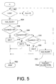
- Figures 4, 5, and 6 are flow charts of the operation of controller 234 as it determines the gear ratio of gearbox 116. This is a threefold process.
- controller 234 In the first stage, shown in Figure 4, controller 234 repeatedly calculates the motor/rotor speed ratio and the corresponding gear ratio of the gearbox 116 fifty times in a row. Each time through, it calculates which of the three gear ratios the gearbox is engaged in: first, second or third gear. It repeats this process at least twice, preferably fifty times. Controller 234 simultaneously calculates three sums that are stored in three variables: Counter[0], which indicates how many times controller 234 calculates first gear as the gear ratio; Counter[1], which indicates how many times controller 234 calculates second gear as the gear ratio; and Counter[2], which indicates how many times controller 234 calculates third gear as the gear ratio.
- controller 234 sums the results of the gear ratio calculations, keeping a running count or sum for each of the three gear ratios it determines.
- the speed ratio is the ratio of the motor speed (an input to the gearbox 116) and the rotor speed (an output from the gearbox).
- the second stage selects between these three sums (i.e. selects between the first, second and third gear ratios) to determine which of these three gear ratios the gearbox is actually engaged in. Theoretically, all the calculated gear ratios should be the same, but due to clutch slippage, sensor errors and other effects, not all of the fifty gear ratio calculations may be the same.
- the controller 234 determines which of the three sums (i.e. Counter[0], Counter[1], or Counter[2]) exceeds a minimum value. In this case, the minimum value is 30 (i.e. controller 234 selected a gear ratio 30 times out of a possible 50 times).
- controller 234 calculated one of the three gear ratios at least 30 out of 50 total times, the sum corresponding to that gear ratio will be greater than the sum corresponding to either of the other two gear ratios. Any gear ratio selected in this stage has a sum that is greater than the other sums. If none of the sums is greater than the threshold value of 30, then the first gear ratio determination process fails.
- the third stage is performed when the first gear ratio determination process fails.
- the controller waits a predetermined time interval. After that time interval, controller 234 calculates the speed ratio and determines the gearbox gear ratio based on that calculation. This process is repeatedly performed over a second time interval. At the end of this interval, controller 234 saves the last gear ratio it successfully determined as the correct gear ratio. Controller 234 does not sum its choices and select between them as it does in the first and second stages of the process.
- the speed ratio that controller 234 calculates here is the engine-to-rotor speed ratio. If both processes to determine the speed range fail, the last known valid gear selection would be used.
- Controller 234 then checks to see whether the rotor speed has stabilized and is ready to be checked (block 402). The speed is stabilized when controller 234 has accelerated the rotor 118 for 1.5 seconds (i.e. when "i" is equal to or greater than 150 in block 402).
- controller 234 reads the motor speed sensor 254 and the rotor speed sensor 252 and calculates the speed ratio--the ratio of the two (block 406). This speed ratio indicates the gear ratio of gearbox 116.
- controller 234 checks the speed ratio to see if it is within a range of 8 and 15. If it is, then controller 234 increments Counter[2], indicating that it has determined the gearbox to be in third gear. When gearbox 116 is in third gear, the actual speed ratio will be about 11. Rather than checking to see if the ratio is precisely 11 (as it should be if the gearbox is in third gear) the 8-15 range in block 406 accommodates for minor system errors.
- controller 234 continues to block 410 and checks to see if the speed ratio is between 15 and 25. If it is, controller 234 increments Counter[1], indicating that it has determined the gearbox 116 to be in second gear. When gearbox 116 is in second gear, the actual speed ratio will be about 20. Rather than checking to see if the ratio is precisely 20 (as it should be if the gearbox is in second gear) the range of 15-25 in block 408 accommodates minor system errors.
- controller 234 continues to block 412 and checks to see if the speed ratio is between 25 and 40. If it is, controller 234 increments Counter[0], indicating that it has determined the gearbox 116 to be in first gear. When gearbox 116 is in first gear, the actual speed ratio will be about 32.5. Rather than checking to see if the ratio is precisely 32.5 (as it should be if the gearbox is in first gear) the 25-40 range in block 410 accommodates minor system errors.
- controller 234 does not increment Counter[0], Counter[1], or Counter[2].
- Controller 234 proceeds to increment the time counter, "i" (block 420), and returns to block 404.
- Controller 234 stays in the block 404-420 loop for 0.5 seconds (until i>199 in block 404) calculating fifty successive speed ratios, one calculated every ten milliseconds. Controller 234 simultaneously characterizes each of the fifty as representing the gearbox gear ratio as first, second or third gear.
- the second stage of gear ratio determination determines (1) which gear ratio was calculated more times than any others (i.e. 30 times, all others being calculated 20 times or less), (2) which gear ratio was calculated the majority of the times (i.e. 30 times out of a total of 50 times), and (3) which gear ratio was calculated more than a predetermined number of times (i.e. 30 times). This process is shown in Figure 5.
- controller 234 proceeds to examine the 50 calculated gear ratios (the three sums, Counter[0], Counter[1] and Counter[2]) and to decide which of the three gear ratios is correct. This further processing occurs when the time counter reaches 200.
- controller 234 When the time counter "i" reaches 200 and the 500 milliseconds of gear ratio calculations are finished, controller 234 will answer “no” to block 404. It will then continue to tag “A” ( Figure 5) and execute block 502. In block 502, controller 234 checks to see if time counter i equals 200, which it does. Controller 234 continues to block 504 and sets the flag "gear_found” equal to 1.
- controller 234 executes block 508, checking Counter[1] to see if it is at least 30.
- controller 234 then executes block 510, checking Counter[2] to see if it is at least 30.
- controller 234 determines the gear ratio was first, second or third gear, then processing stops--the gear ratio determination process is complete, per block 522.
- controller 234 sets the gear found flag to false (i.e. "0") in block 512, "i" is incremented (block 514) and processing returns to block 502.
- controller 234 will answer “no” in block 502 and continue processing at block 602 in Figure 6.
- Controller 234 has now delayed until the rotor speed has stabilized with both the motor 112 and the engine 104 driving the rotor 118 at a stable speed (see FIG 3 and accompanying description).
- controller 234 continues to block 606, in which it checks to see if the time counter has reached 462, or 4.62 seconds into rotor acceleration process. When the time counter i reaches 462, controller 234 halts the gear estimation process (block 608).
- controller 234 executes the program steps shown in blocks 610-624.
- controller 234 reads the engine speed sensor 256 and the rotor speed sensor 252 and saves the values. It then continues to block 612 where it examines the rotor speed (RS) to see if it is less than 0.152 times the engine speed (ES). In other words, to see if the engine-to-rotor speed ratio is less than 0.152.
- controller 234 continues to block 616, where it checks to see if RS is between 0.152 times ES and 0.243 times ES. In other words, to see if the engine-to-rotor speed ratio is greater than or equal to 0.152 and less than 0.243. If the answer is "yes”, controller 234 continues to block 618, where it sets ratio equal to 2, which indicates that gearbox 116 is in second gear.
- controller 234 continues to block 620, where it checks to see if RS is between 0.243 times ES and 0.58 times ES. Expressed differently, it checks to see if the engine-to-rotor speed ratio is greater than or equal to 0.243 and less than 0.58. If the answer is "yes”, controller 234 continues to block 622, where it sets ratio equal to 3, which indicates that gearbox 116 is in third gear.
- controller 234 Having set "ratio” to either 1, 2, or 3 (or having not set “ratio” at all because the three tests of blocks 612, 616, 620 failed to identify a proper gear ratio), controller 234 then increments "i” (in block 624) and returns to block 606, where it again checks to see if "i” has reached 462.
- controller 234 After looping through blocks 606-624 several times, incrementing "i" on each pass, controller 234 will eventually go to block 608 and stop. This terminates the gear ratio determination process.
- the gear ratio that controller 234 finally determines in Figure 6, is the last gear ratio selected in any of blocks 612, 616, 620.
- the combine 100 has a control system that calculates gear ratios based upon rotor speed signals, engine speed signals and motor speed signals.
Landscapes
- Engineering & Computer Science (AREA)
- General Engineering & Computer Science (AREA)
- Mechanical Engineering (AREA)
- Control Of Transmission Device (AREA)
Applications Claiming Priority (2)
| Application Number | Priority Date | Filing Date | Title |
|---|---|---|---|
| US10/783,547 US7058496B2 (en) | 2004-02-20 | 2004-02-20 | Method and apparatus for determining a vehicle gear ratio |
| US783547 | 2004-02-20 |
Publications (3)
| Publication Number | Publication Date |
|---|---|
| EP1571375A2 true EP1571375A2 (de) | 2005-09-07 |
| EP1571375A3 EP1571375A3 (de) | 2014-06-18 |
| EP1571375B1 EP1571375B1 (de) | 2018-11-14 |
Family
ID=34750456
Family Applications (1)
| Application Number | Title | Priority Date | Filing Date |
|---|---|---|---|
| EP05101199.7A Expired - Lifetime EP1571375B1 (de) | 2004-02-20 | 2005-02-17 | Verfahren und Vorrichtung zur Bestimmung der Übersetzung des Getriebes |
Country Status (2)
| Country | Link |
|---|---|
| US (1) | US7058496B2 (de) |
| EP (1) | EP1571375B1 (de) |
Families Citing this family (3)
| Publication number | Priority date | Publication date | Assignee | Title |
|---|---|---|---|---|
| US20060155448A1 (en) * | 2005-01-12 | 2006-07-13 | Shah Vaibhav H | Upshift in hydrostatic drive work machine |
| US8412428B2 (en) | 2010-05-28 | 2013-04-02 | Honda Motor Co., Ltd. | System for and method of detecting clutch engagement of a manual transmission |
| US8452500B1 (en) * | 2012-02-28 | 2013-05-28 | Caterpillar Inc. | Multi-range hydro-mechanical transmission |
Citations (1)
| Publication number | Priority date | Publication date | Assignee | Title |
|---|---|---|---|---|
| US20030229432A1 (en) | 2002-06-11 | 2003-12-11 | Case Corporation | Combine having a system estimator to automatically estimate and dynamically change a target control parameter in a control algorithm |
Family Cites Families (23)
| Publication number | Priority date | Publication date | Assignee | Title |
|---|---|---|---|---|
| US229432A (en) * | 1880-06-29 | Nathan b | ||
| US228893A (en) * | 1880-06-15 | Uei haskin | ||
| US226707A (en) * | 1880-04-20 | Hezekiah h | ||
| US3836A (en) * | 1844-11-26 | Stereotyping | ||
| JPS5761849A (en) * | 1980-09-29 | 1982-04-14 | Nissan Motor Co Ltd | Speed change gear position detector |
| US4799158A (en) * | 1986-05-27 | 1989-01-17 | Ford Motor Company | System for computer controlled shifting of an automatic transmission |
| US4821190A (en) * | 1986-05-27 | 1989-04-11 | Ford Motor Company | Closed loop computer control for an automatic transmission |
| DE4305054A1 (de) * | 1993-02-18 | 1994-08-25 | Steyr Daimler Puch Ag | Antriebsvorrichtung für ein Elektromobil |
| JP2600061B2 (ja) * | 1993-07-14 | 1997-04-16 | 株式会社小松製作所 | 装軌車の操向装置 |
| NO314174B1 (no) * | 1995-12-18 | 2003-02-10 | Luk Getriebe Systeme Gmbh | Motorkjöretöy |
| DE19601618A1 (de) * | 1996-01-18 | 1997-07-24 | Zahnradfabrik Friedrichshafen | Sicherheitssystem für ein Automatgetriebe |
| US5974354A (en) * | 1997-02-05 | 1999-10-26 | Eaton Corporation | Engagement of gear ratio confirmation |
| JP3262046B2 (ja) * | 1997-09-17 | 2002-03-04 | トヨタ自動車株式会社 | ギヤ機構における歯打ち音の低減方法、動力出力装置およびこの動力出力装置を搭載したハイブリッド車輌 |
| JP3153527B2 (ja) * | 1999-04-05 | 2001-04-09 | 本田技研工業株式会社 | ハイブリッド自動車の制御装置 |
| US6202016B1 (en) * | 1999-08-10 | 2001-03-13 | Eaton Corporation | Shift on the go transmission system |
| JP4274643B2 (ja) * | 1999-09-06 | 2009-06-10 | 本田技研工業株式会社 | 内燃機関の制御装置 |
| EP1084954B1 (de) * | 1999-09-15 | 2006-07-05 | Focke & Co. (GmbH & Co. KG) | Verfahren und Vorrichtung zum Herstellen von Zigarettenpackungen |
| US6343250B1 (en) * | 2000-05-19 | 2002-01-29 | Caterpillar Inc. | Method and apparatus for smoothing the output of a hydrostatic transmission near zero speed |
| US6490517B1 (en) * | 2001-06-29 | 2002-12-03 | Daimlerchrysler Corporation | Filter method for engine speed to vehicle speed ratios |
| DE10131573A1 (de) | 2001-07-02 | 2003-01-16 | Bosch Gmbh Robert | Verfahren zum Schutz eines Steuergeräts eines Kraftfahrzeugs vor Manipulation |
| US6609056B1 (en) * | 2002-02-15 | 2003-08-19 | Daimlerchrysler Corporation | Adaptive load torque for gear selection in an automatic transmission |
| US6702666B2 (en) | 2002-06-11 | 2004-03-09 | Case, Llc | Combine having a system estimator to monitor hydraulic system pressure |
| US6695693B2 (en) | 2002-06-11 | 2004-02-24 | Case Llc | Combine having a system estimator to monitor hydraulic system pressure |
-
2004
- 2004-02-20 US US10/783,547 patent/US7058496B2/en not_active Expired - Lifetime
-
2005
- 2005-02-17 EP EP05101199.7A patent/EP1571375B1/de not_active Expired - Lifetime
Patent Citations (1)
| Publication number | Priority date | Publication date | Assignee | Title |
|---|---|---|---|---|
| US20030229432A1 (en) | 2002-06-11 | 2003-12-11 | Case Corporation | Combine having a system estimator to automatically estimate and dynamically change a target control parameter in a control algorithm |
Also Published As
| Publication number | Publication date |
|---|---|
| US7058496B2 (en) | 2006-06-06 |
| EP1571375A3 (de) | 2014-06-18 |
| EP1571375B1 (de) | 2018-11-14 |
| US20050187691A1 (en) | 2005-08-25 |
Similar Documents
| Publication | Publication Date | Title |
|---|---|---|
| US7096105B2 (en) | Combine having a system estimator to automatically estimate and dynamically change a target control parameter in a control algorithm | |
| US6702666B2 (en) | Combine having a system estimator to monitor hydraulic system pressure | |
| US7632179B2 (en) | System and method for detecting combine rotor slugging | |
| DE19581387B4 (de) | Vorrichtung und Verfahren zum Detektieren eines Fehlerzustandes in einem Getriebe | |
| US4495457A (en) | Method of preventing erroneous gear selection in a vehicle transmission | |
| EP0310275B1 (de) | Schaltmusteränderung für ein elektronisch gesteuertes Getriebe im Fehlerfall | |
| CA1306530C (en) | Steady state slip detection/correction for a motor vehicle transmission | |
| CN104373595B (zh) | 机械式自动变速器amt的挡位识别方法和故障诊断方法 | |
| KR920008094B1 (ko) | 자동차변속기에 대한 출력속도센서 감지진단제어방법 | |
| KR20120046170A (ko) | 클러치 접촉점 | |
| US9115772B2 (en) | System and method for automatically calibrating the clutches within a transmission of a work vehicle | |
| US7072748B2 (en) | Method for diagnosing a failure of an output shaft speed sensor of an automatic transmission for a vehicle | |
| US6695693B2 (en) | Combine having a system estimator to monitor hydraulic system pressure | |
| EP1571375B1 (de) | Verfahren und Vorrichtung zur Bestimmung der Übersetzung des Getriebes | |
| CN104132127A (zh) | 一种双离合器自动变速器跛行回家控制方法 | |
| US7427231B2 (en) | Motor overspeed detection | |
| CN112867653B (zh) | 响应于发动机通信丢失来控制变速器档位的方法及其系统 | |
| CN104089004A (zh) | 一种双离合器自动变速器跛行回家控制方法 | |
| EP1967769A1 (de) | Übetragungssteuervorrichtung für eine arbeitsmaschine | |
| CN109312854A (zh) | 估算无级变速器中的扭矩的方法 | |
| CN113295407B (zh) | 变速箱的断轴检测方法、装置及工程车辆 | |
| CN106555873B (zh) | 用于自动变速装置的换挡控制 | |
| JP2893261B2 (ja) | 自動変速機のロックアップクラッチ制御装置 | |
| JPH06331020A (ja) | トルクコンバータ付自動変速機のトルクコンバータ出力軸回転速度推定装置,変速位置推定装置及び故障診断装置 | |
| JPH05256169A (ja) | エンジン駆動系制御装置 |
Legal Events
| Date | Code | Title | Description |
|---|---|---|---|
| PUAI | Public reference made under article 153(3) epc to a published international application that has entered the european phase |
Free format text: ORIGINAL CODE: 0009012 |
|
| AK | Designated contracting states |
Kind code of ref document: A2 Designated state(s): AT BE BG CH CY CZ DE DK EE ES FI FR GB GR HU IE IS IT LI LT LU MC NL PL PT RO SE SI SK TR |
|
| AX | Request for extension of the european patent |
Extension state: AL BA HR LV MK YU |
|
| RAP1 | Party data changed (applicant data changed or rights of an application transferred) |
Owner name: CNH INDUSTRIAL BELGIUM NV |
|
| PUAL | Search report despatched |
Free format text: ORIGINAL CODE: 0009013 |
|
| AK | Designated contracting states |
Kind code of ref document: A3 Designated state(s): AT BE BG CH CY CZ DE DK EE ES FI FR GB GR HU IE IS IT LI LT LU MC NL PL PT RO SE SI SK TR |
|
| AX | Request for extension of the european patent |
Extension state: AL BA HR LV MK YU |
|
| RIC1 | Information provided on ipc code assigned before grant |
Ipc: F16H 59/70 20060101AFI20140515BHEP |
|
| 17P | Request for examination filed |
Effective date: 20141218 |
|
| RBV | Designated contracting states (corrected) |
Designated state(s): AT BE BG CH CY CZ DE DK EE ES FI FR GB GR HU IE IS IT LI LT LU MC NL PL PT RO SE SI SK TR |
|
| AKX | Designation fees paid |
Designated state(s): AT BE BG CH CY CZ DE DK EE ES FI FR GB GR HU IE IS IT LI LT LU MC NL PL PT RO SE SI SK TR |
|
| AXX | Extension fees paid |
Extension state: AL Extension state: LV Extension state: BA Extension state: HR Extension state: YU Extension state: MK |
|
| GRAP | Despatch of communication of intention to grant a patent |
Free format text: ORIGINAL CODE: EPIDOSNIGR1 |
|
| STAA | Information on the status of an ep patent application or granted ep patent |
Free format text: STATUS: GRANT OF PATENT IS INTENDED |
|
| INTG | Intention to grant announced |
Effective date: 20180614 |
|
| GRAS | Grant fee paid |
Free format text: ORIGINAL CODE: EPIDOSNIGR3 |
|
| GRAA | (expected) grant |
Free format text: ORIGINAL CODE: 0009210 |
|
| STAA | Information on the status of an ep patent application or granted ep patent |
Free format text: STATUS: THE PATENT HAS BEEN GRANTED |
|
| AK | Designated contracting states |
Kind code of ref document: B1 Designated state(s): AT BE BG CH CY CZ DE DK EE ES FI FR GB GR HU IE IS IT LI LT LU MC NL PL PT RO SE SI SK TR |
|
| REG | Reference to a national code |
Ref country code: GB Ref legal event code: FG4D |
|
| REG | Reference to a national code |
Ref country code: CH Ref legal event code: EP Ref country code: AT Ref legal event code: REF Ref document number: 1065213 Country of ref document: AT Kind code of ref document: T Effective date: 20181115 |
|
| REG | Reference to a national code |
Ref country code: DE Ref legal event code: R096 Ref document number: 602005054968 Country of ref document: DE |
|
| REG | Reference to a national code |
Ref country code: IE Ref legal event code: FG4D |
|
| REG | Reference to a national code |
Ref country code: NL Ref legal event code: MP Effective date: 20181114 |
|
| REG | Reference to a national code |
Ref country code: LT Ref legal event code: MG4D |
|
| REG | Reference to a national code |
Ref country code: AT Ref legal event code: MK05 Ref document number: 1065213 Country of ref document: AT Kind code of ref document: T Effective date: 20181114 |
|
| PG25 | Lapsed in a contracting state [announced via postgrant information from national office to epo] |
Ref country code: AT Free format text: LAPSE BECAUSE OF FAILURE TO SUBMIT A TRANSLATION OF THE DESCRIPTION OR TO PAY THE FEE WITHIN THE PRESCRIBED TIME-LIMIT Effective date: 20181114 Ref country code: FI Free format text: LAPSE BECAUSE OF FAILURE TO SUBMIT A TRANSLATION OF THE DESCRIPTION OR TO PAY THE FEE WITHIN THE PRESCRIBED TIME-LIMIT Effective date: 20181114 Ref country code: BG Free format text: LAPSE BECAUSE OF FAILURE TO SUBMIT A TRANSLATION OF THE DESCRIPTION OR TO PAY THE FEE WITHIN THE PRESCRIBED TIME-LIMIT Effective date: 20190214 Ref country code: LT Free format text: LAPSE BECAUSE OF FAILURE TO SUBMIT A TRANSLATION OF THE DESCRIPTION OR TO PAY THE FEE WITHIN THE PRESCRIBED TIME-LIMIT Effective date: 20181114 Ref country code: ES Free format text: LAPSE BECAUSE OF FAILURE TO SUBMIT A TRANSLATION OF THE DESCRIPTION OR TO PAY THE FEE WITHIN THE PRESCRIBED TIME-LIMIT Effective date: 20181114 Ref country code: IS Free format text: LAPSE BECAUSE OF FAILURE TO SUBMIT A TRANSLATION OF THE DESCRIPTION OR TO PAY THE FEE WITHIN THE PRESCRIBED TIME-LIMIT Effective date: 20190314 |
|
| PG25 | Lapsed in a contracting state [announced via postgrant information from national office to epo] |
Ref country code: GR Free format text: LAPSE BECAUSE OF FAILURE TO SUBMIT A TRANSLATION OF THE DESCRIPTION OR TO PAY THE FEE WITHIN THE PRESCRIBED TIME-LIMIT Effective date: 20190215 Ref country code: NL Free format text: LAPSE BECAUSE OF FAILURE TO SUBMIT A TRANSLATION OF THE DESCRIPTION OR TO PAY THE FEE WITHIN THE PRESCRIBED TIME-LIMIT Effective date: 20181114 Ref country code: PT Free format text: LAPSE BECAUSE OF FAILURE TO SUBMIT A TRANSLATION OF THE DESCRIPTION OR TO PAY THE FEE WITHIN THE PRESCRIBED TIME-LIMIT Effective date: 20190314 Ref country code: SE Free format text: LAPSE BECAUSE OF FAILURE TO SUBMIT A TRANSLATION OF THE DESCRIPTION OR TO PAY THE FEE WITHIN THE PRESCRIBED TIME-LIMIT Effective date: 20181114 |
|
| PG25 | Lapsed in a contracting state [announced via postgrant information from national office to epo] |
Ref country code: DK Free format text: LAPSE BECAUSE OF FAILURE TO SUBMIT A TRANSLATION OF THE DESCRIPTION OR TO PAY THE FEE WITHIN THE PRESCRIBED TIME-LIMIT Effective date: 20181114 Ref country code: PL Free format text: LAPSE BECAUSE OF FAILURE TO SUBMIT A TRANSLATION OF THE DESCRIPTION OR TO PAY THE FEE WITHIN THE PRESCRIBED TIME-LIMIT Effective date: 20181114 Ref country code: CZ Free format text: LAPSE BECAUSE OF FAILURE TO SUBMIT A TRANSLATION OF THE DESCRIPTION OR TO PAY THE FEE WITHIN THE PRESCRIBED TIME-LIMIT Effective date: 20181114 |
|
| REG | Reference to a national code |
Ref country code: DE Ref legal event code: R097 Ref document number: 602005054968 Country of ref document: DE |
|
| PG25 | Lapsed in a contracting state [announced via postgrant information from national office to epo] |
Ref country code: SK Free format text: LAPSE BECAUSE OF FAILURE TO SUBMIT A TRANSLATION OF THE DESCRIPTION OR TO PAY THE FEE WITHIN THE PRESCRIBED TIME-LIMIT Effective date: 20181114 Ref country code: EE Free format text: LAPSE BECAUSE OF FAILURE TO SUBMIT A TRANSLATION OF THE DESCRIPTION OR TO PAY THE FEE WITHIN THE PRESCRIBED TIME-LIMIT Effective date: 20181114 Ref country code: RO Free format text: LAPSE BECAUSE OF FAILURE TO SUBMIT A TRANSLATION OF THE DESCRIPTION OR TO PAY THE FEE WITHIN THE PRESCRIBED TIME-LIMIT Effective date: 20181114 |
|
| PLBE | No opposition filed within time limit |
Free format text: ORIGINAL CODE: 0009261 |
|
| STAA | Information on the status of an ep patent application or granted ep patent |
Free format text: STATUS: NO OPPOSITION FILED WITHIN TIME LIMIT |
|
| REG | Reference to a national code |
Ref country code: CH Ref legal event code: PL |
|
| 26N | No opposition filed |
Effective date: 20190815 |
|
| PG25 | Lapsed in a contracting state [announced via postgrant information from national office to epo] |
Ref country code: SI Free format text: LAPSE BECAUSE OF FAILURE TO SUBMIT A TRANSLATION OF THE DESCRIPTION OR TO PAY THE FEE WITHIN THE PRESCRIBED TIME-LIMIT Effective date: 20181114 Ref country code: MC Free format text: LAPSE BECAUSE OF FAILURE TO SUBMIT A TRANSLATION OF THE DESCRIPTION OR TO PAY THE FEE WITHIN THE PRESCRIBED TIME-LIMIT Effective date: 20181114 Ref country code: LU Free format text: LAPSE BECAUSE OF NON-PAYMENT OF DUE FEES Effective date: 20190217 |
|
| REG | Reference to a national code |
Ref country code: IE Ref legal event code: MM4A |
|
| PG25 | Lapsed in a contracting state [announced via postgrant information from national office to epo] |
Ref country code: LI Free format text: LAPSE BECAUSE OF NON-PAYMENT OF DUE FEES Effective date: 20190228 Ref country code: CH Free format text: LAPSE BECAUSE OF NON-PAYMENT OF DUE FEES Effective date: 20190228 |
|
| PG25 | Lapsed in a contracting state [announced via postgrant information from national office to epo] |
Ref country code: IE Free format text: LAPSE BECAUSE OF NON-PAYMENT OF DUE FEES Effective date: 20190217 |
|
| PG25 | Lapsed in a contracting state [announced via postgrant information from national office to epo] |
Ref country code: TR Free format text: LAPSE BECAUSE OF FAILURE TO SUBMIT A TRANSLATION OF THE DESCRIPTION OR TO PAY THE FEE WITHIN THE PRESCRIBED TIME-LIMIT Effective date: 20181114 |
|
| PGFP | Annual fee paid to national office [announced via postgrant information from national office to epo] |
Ref country code: GB Payment date: 20200219 Year of fee payment: 16 Ref country code: IT Payment date: 20200211 Year of fee payment: 16 |
|
| PGFP | Annual fee paid to national office [announced via postgrant information from national office to epo] |
Ref country code: BE Payment date: 20200219 Year of fee payment: 16 |
|
| REG | Reference to a national code |
Ref country code: DE Ref legal event code: R084 Ref document number: 602005054968 Country of ref document: DE |
|
| PG25 | Lapsed in a contracting state [announced via postgrant information from national office to epo] |
Ref country code: CY Free format text: LAPSE BECAUSE OF FAILURE TO SUBMIT A TRANSLATION OF THE DESCRIPTION OR TO PAY THE FEE WITHIN THE PRESCRIBED TIME-LIMIT Effective date: 20181114 |
|
| PG25 | Lapsed in a contracting state [announced via postgrant information from national office to epo] |
Ref country code: HU Free format text: LAPSE BECAUSE OF FAILURE TO SUBMIT A TRANSLATION OF THE DESCRIPTION OR TO PAY THE FEE WITHIN THE PRESCRIBED TIME-LIMIT; INVALID AB INITIO Effective date: 20050217 |
|
| GBPC | Gb: european patent ceased through non-payment of renewal fee |
Effective date: 20210217 |
|
| REG | Reference to a national code |
Ref country code: BE Ref legal event code: MM Effective date: 20210228 |
|
| PG25 | Lapsed in a contracting state [announced via postgrant information from national office to epo] |
Ref country code: GB Free format text: LAPSE BECAUSE OF NON-PAYMENT OF DUE FEES Effective date: 20210217 |
|
| PG25 | Lapsed in a contracting state [announced via postgrant information from national office to epo] |
Ref country code: IT Free format text: LAPSE BECAUSE OF NON-PAYMENT OF DUE FEES Effective date: 20210217 |
|
| PGFP | Annual fee paid to national office [announced via postgrant information from national office to epo] |
Ref country code: DE Payment date: 20220221 Year of fee payment: 18 |
|
| PGFP | Annual fee paid to national office [announced via postgrant information from national office to epo] |
Ref country code: FR Payment date: 20220219 Year of fee payment: 18 |
|
| PG25 | Lapsed in a contracting state [announced via postgrant information from national office to epo] |
Ref country code: BE Free format text: LAPSE BECAUSE OF NON-PAYMENT OF DUE FEES Effective date: 20210228 |
|
| REG | Reference to a national code |
Ref country code: DE Ref legal event code: R119 Ref document number: 602005054968 Country of ref document: DE |
|
| PG25 | Lapsed in a contracting state [announced via postgrant information from national office to epo] |
Ref country code: FR Free format text: LAPSE BECAUSE OF NON-PAYMENT OF DUE FEES Effective date: 20230228 Ref country code: DE Free format text: LAPSE BECAUSE OF NON-PAYMENT OF DUE FEES Effective date: 20230901 |