EP1571261A1 - Machine de brossage - Google Patents
Machine de brossage Download PDFInfo
- Publication number
- EP1571261A1 EP1571261A1 EP05290483A EP05290483A EP1571261A1 EP 1571261 A1 EP1571261 A1 EP 1571261A1 EP 05290483 A EP05290483 A EP 05290483A EP 05290483 A EP05290483 A EP 05290483A EP 1571261 A1 EP1571261 A1 EP 1571261A1
- Authority
- EP
- European Patent Office
- Prior art keywords
- machine
- brush
- brushing machine
- brushing
- hydraulic
- Prior art date
- Legal status (The legal status is an assumption and is not a legal conclusion. Google has not performed a legal analysis and makes no representation as to the accuracy of the status listed.)
- Granted
Links
Images


Classifications
-
- E—FIXED CONSTRUCTIONS
- E01—CONSTRUCTION OF ROADS, RAILWAYS, OR BRIDGES
- E01H—STREET CLEANING; CLEANING OF PERMANENT WAYS; CLEANING BEACHES; DISPERSING OR PREVENTING FOG IN GENERAL CLEANING STREET OR RAILWAY FURNITURE OR TUNNEL WALLS
- E01H1/00—Removing undesirable matter from roads or like surfaces, with or without moistening of the surface
- E01H1/02—Brushing apparatus, e.g. with auxiliary instruments for mechanically loosening dirt
- E01H1/04—Brushing apparatus, e.g. with auxiliary instruments for mechanically loosening dirt taking- up the sweepings, e.g. for collecting, for loading
- E01H1/045—Brushing apparatus, e.g. with auxiliary instruments for mechanically loosening dirt taking- up the sweepings, e.g. for collecting, for loading the loading means being a rotating brush with horizontal axis
-
- E—FIXED CONSTRUCTIONS
- E01—CONSTRUCTION OF ROADS, RAILWAYS, OR BRIDGES
- E01H—STREET CLEANING; CLEANING OF PERMANENT WAYS; CLEANING BEACHES; DISPERSING OR PREVENTING FOG IN GENERAL CLEANING STREET OR RAILWAY FURNITURE OR TUNNEL WALLS
- E01H1/00—Removing undesirable matter from roads or like surfaces, with or without moistening of the surface
- E01H1/02—Brushing apparatus, e.g. with auxiliary instruments for mechanically loosening dirt
- E01H1/05—Brushing apparatus, e.g. with auxiliary instruments for mechanically loosening dirt with driven brushes
- E01H1/056—Brushing apparatus, e.g. with auxiliary instruments for mechanically loosening dirt with driven brushes having horizontal axes
Definitions
- the present invention relates to a brushing machine intended to be moved on a surface for cleaning, the machine comprising a pair of flanges mounted in an articulated manner and between which is mounted a rotary brush cleaning device adapted to be rotated by means of an engine hydraulic, the flanges being driven by means of at least one jack hydraulic device capable of modifying the position of the rotary brush with respect to said machine.
- a brushing machine for cleaning surfaces approximately planes and horizontales generally comprises a frame provided with wheels adapted to allow it to move on said surface and in which a brush is mounted cylindrical rotating machine whose axis of rotation is arranged parallel to the ground and which can be driven in rotation, by means of a drive motor, during the moving said machine on the ground.
- a tray, arranged in the rear part of the machine, allows to recover the dirt removed by the brush.
- the brush finishes, over time, by wear so well that its outer diameter decreases gradually resulting in corollary way a gradual decrease in the efficiency of cleaning.
- the surface of the soil to be cleaned is not always flat or present deformations resulting in a variable efficiency of the cleaning.
- Some brushing machines are thus equipped with adjusting devices the vertical position of the wheels to lower or raise the machines to the ground and therefore to adjust the distance between the axis of rotation of the brushes in relation to the ground.
- Such a brushing machine can thus comprise a cradle, mounted by being hinged to the frame of the machine to support floating, against a spring, the rotating brush.
- the brushing machine can still, as described in EP-A-1 152 089, comprising a articulated arm on the frame of the machine and which supports at its free end the axis of the brush driven by an electric motor.
- An electric cylinder assisted by a spring device, is mounted on the machine so as to be able to modify the inclination of the arm and therefore the height position of the brush relative on the ground on which the machine rests.
- a sensor of the current consumption of the electric motor of the brush and a control unit are provided in the machine for controlling the operation of the electric jack adapted to move the articulated arm.
- the control unit of the machine controls the operation of the electric cylinder so that it can lower the brush or raise it.
- the compensation device of this machine may be in able to raise and lower the brush automatically, the force exerted by the spring device on the brush is not constant on the stroke of the device, so that the cleaning efficiency is not constant.
- the object of the invention is therefore to propose a brushing machine whose brush can be applied on the floor to be cleaned according to a constant effort whatever either its degree of wear or whatever the relief of the surface to be cleaned.
- a brushing machine is proposed to be moved on a surface for cleaning it, the machine comprising a pair of mounted flanges of articulated manner on said machine and between which is mounted a rotary brush cleaning device adapted to be rotated by means of an engine hydraulic, the flanges being driven by means of at least one jack hydraulically adapted to change the position of the rotary brush relative to the machine, said machine being remarkable in that the exhaust system of the engine connected to the upstream and downstream chambers of said or each hydraulic cylinder so that said or each hydraulic cylinder can apply the rotating brush on the surface to be cleaned by exerting on it a force of constant intensity in a particular range of pressure measured in the intake circuit of the hydraulic motor.
- the rotating brush can automatically and flexibly follow the relief of the surface to be cleaned when moving the brushing machine over said surface.
- the cleaning efficiency of the surface is increased and the wear of the brush is reduced compared to the services offered by brushing machines known.
- the machine adapts automatically, during its operation, to the diameter of the brush that it uses or its degree of wear, as well as the asperities of the ground.
- a distributor is connected to the supply circuit of the downstream chamber of said or each jack the distributor being provided with a pilot pre-actuator with a threshold of fluid pressure that is connected to the intake circuit of the hydraulic motor of so that the elevation of the pressure in the intake circuit of the pump hydraulics beyond a given threshold may control the piloting of the distributor so that the downstream chamber of said or each hydraulic cylinder can be put into communication with the hydraulic motor intake circuit for wind the rotating brush.
- the brush is thus automatically positioned in a position of clearance when encountering an obstacle or when it is overloaded.
- an adjusting means is provided on the pre-actuator for modify the pressure threshold triggering it.
- an alarm is associated triggering the pre-actuator thus making it possible to warn the operator using the machine that an overload problem has occurred in the operation of the brush.
- the distributor is a proportional distributor.
- the brushing machine is provided with a control member, located in the cabin of a maneuvering machine of the latter, and which makes it possible to act on the operating pressure of said or of each hydraulic cylinder. In this way, it is possible to act on the application pressure of the brush on the surface to be cleaned.
- the machine comprises two parts articulated relative to each other, the first part including the brush rotating, the second part including a device for collecting dirt, a means of maneuver being provided to move the first part relative to the second part between a working position of the brushing machine where the rotating brush is adapted to project dirt into the collection device and an open position said machine for emptying the collection device.
- the maneuver of the brushing machine in one or the other of these positions is thus assisted.
- the machine is provided with a torsion limiting device for limiting the angular displacement between the two flanges during operation of said brushing machine.
- the limiter device of torsion consists of a pair of toothed wheels respectively meshing on racks made on one of the edges of the flanges and which are joined by via a torsion shaft.
- the machine is provided with handling devices intended to allow a self-propelled push, pull or lift.
- the rotary brush is provided with a hollow hub fixed at its ends to the flanges by means of turntables.
- the hollow hub advantageously has a polygonal section and around which is threaded the rotary brush and at least one vertex has a groove adapted to receive a lug provided in a hollow tube constituting the brush rotary to allow its rotational drive.
- the hollow hub is internally provided, and at a end, of a shaft held by rolling means, mounted in a sleeve of a platinum, its other end being provided with a drive shaft in which is mounted a splined shaft of the hydraulic motor fixed in a sleeve of the other platinum for rotating the rotating brush, the shaft passing through the hollow hub so that its other end can be housed in the nut drive.
- the machine is provided with a first scraper mounted between the rotating brush and the collection device for improve the separation of dirt retained on the rotating brush to allow their ejection in the collection device.
- the scraper also optimizes the work of scraping the brush avoiding heaping when the brush is raised.
- the first scraper consists of a rectangular blade between a pair of plates and one edge of which can be positioned to tangent the bristles of the rotating brush.
- the machine is provided with a second scraper disposed inside the brushing machine to allow the automatic cleaning of the rotating brush when the brushing machine is lifted by the machine and that the rotating brush is rotated by its motor drive.
- the machine is provided with at least one additional brush.
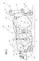
- the brushing machine 100 shown in FIGS. 1 and 2 is intended to be driven by a self-propelled land vehicle such as an agricultural tractor on a surface to clean, for example a roadway, to remove dirt that may have been deposited on said surface. It is provided with a frame 110 supported by wheels 112 adapted to allow the movement of the machine 100 on said surface by the machine.
- a self-propelled land vehicle such as an agricultural tractor
- wheels 112 adapted to allow the movement of the machine 100 on said surface by the machine.
- the frame 110 consists of two parts A and B articulated relative to each other to the other through a hinge 114.
- Part A comprises mainly a rotary brush 130 for rubbing off dirt on a surface to be cleaned
- Part B includes mainly a soil collection device 150 such as a tray.
- the two parts A and B are mobile, under the action of a maneuvering means 120, between a working position of the brushing machine 100 where the part A communicates directly with Part B, as shown in Fig.4, of so that the rotating brush 130 can, during its rotation, project the dirt in the tray 150, and an open position of said machine visible to the Fig. 8 allowing the emptying of the tray 150, the internal cleaning of the machine of Brushing 100.
- the operating means 120 is advantageously constituted in Figs. 1 and 2 by a pair of hydraulic cylinders taking on joints provided respectively on the two parts A and B.
- part A thus consists of two side flanks 116 joined together by an upper wall 117 and between which is mounted the rotary brush 130.
- Part B also consists of two side flanks 118 joined by a bottom 119, the side flanks 118 or the bottom 119 constituting the tank 150.
- the parts A and B are open at their junction zone so that the soiling recovered by the rotary brush 130 can be transferred to the tray 150 of the Part B when both parts A and B are positioned in the working position of the brushing machine 100.
- the frame 110 comprises handling members 122, such as bars cross-sections arranged at the ends of parts A and / or B between their flanks respective sides 116 and 118 to allow the machine to push said machine to 100 brushing, pulling it and possibly lifting it so that it does not can no longer touch the ground so you can move it quickly, to drain 150 tray or clean inside.
- handling members 122 such as bars cross-sections arranged at the ends of parts A and / or B between their flanks respective sides 116 and 118 to allow the machine to push said machine to 100 brushing, pulling it and possibly lifting it so that it does not can no longer touch the ground so you can move it quickly, to drain 150 tray or clean inside.
- a cradle 124 allowing attachment to a machine provided with means of hoist may be associated in a floating manner with handling devices 122 for that the machine can push or pull the brushing machine 100 so that it can rest on the ground by its wheels 112 only under the effect of its own mass.
- the cradle 124 is however designed to allow the machine to lift the machine from 100.
- the cradle 124 advantageously comprises a frame 125 fixed on two handling members 122 and traversed transversely by two bars floating assemblies in lights 126 of a set of plates 127 adapted to be fixed on the machine.
- a pair of flanges 160 is hingedly mounted by via joints 162 provided respectively on the flanks 116 of the part A, to pivotably support the rotary brush 130.
- the flanges 160 are preferably mounted on the outer faces of flanks 116 of part A, as this appears in this FIG. 2.
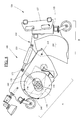
- the rotary brush 130 is provided with a hollow hub 132 secured by its ends flanges 160 via plates 180, 180 '.
- Each plate 180, 180 ' consists of a sleeve 182, 182' fixed against a flange 160 and mounted in one end of the hollow hub 132 to support it to rotation.
- the hollow hub 132 is thus provided internally, and at one end, a shaft 184 held by a rolling means R, such as a ball bearing, mounted in the sleeve 182 of the plate 180, while its other end is provided of a drive shaft 186 in which is mounted the splined shaft of a medium 140 such as a hydraulic motor, fixed in the sleeve 182 'of the other plate 180 ', for the rotational drive of the rotary brush 130.
- a medium 140 such as a hydraulic motor
- the hollow hub 132 advantageously has a polygonal section, for example example a hexagon, and around which is threaded the rotating brush and at least a top has a groove 132 adapted to receive a lug 136 provided in a tube hollow 138 constituting the rotary brush 130.
- each jack 170 is for this purpose assembled from articulated manner, on the one hand, on a first articulation 172 provided on each flank 116 and, secondly, on a second articulation 174 provided on each flange 160. It will be noted that in these Figs., The articulations 172 are common to those used by the hydraulic cylinders of the actuating means 120 to open the brushing machine 100.
- each cylinder 170 can act independently on one end of the hollow hub 132, so that the brush rotary 130 may be laterally inclined to, for example, dislodge dirt deposited in a rut of a road on which the brushing machine is moved.
- the machine of brushing 100 may be provided with a torsion limiting device 200, shown in FIG. Fig. 2, and intended to limit the angular offset between the two flanges 160 during the operation of said brushing machine 100.
- the torsion limiting device 200 is advantageously constituted by a pair of gear wheels 210 meshing respectively on racks 212 made on one of the edges of the flanges 160 and which are joined through a torsion shaft 214 supported by bearings passing through the side flanks 118 of part B.
- the angular offset of flanges 160 is thus limited by the torsion of the torsion shaft 214 during the operation of the brushing machine 100.
- a first scraper 230 visible at FIG. 4 is mounted between the rotary brush 130 and the tray 150.
- a rectangular blade fixed between a pair of plates mounted free to pivot along an axis parallel to that of the rotating brush 130 being arranged in the lower part of part A. positioning of the blade is such that one of its edges can be arranged so as to it can tangent the bristles of the rotating brush 130.
- a device for clamping such as bolts, allows to clamp in position the pair of plates against the flanges 116.
- a second scraper 240 is disposed inside part A, in its part low and frontal, to allow automatic cleaning of the rotating brush 130 when the brushing machine 100 is lifted from the ground by the machine and the brush rotary 130 is rotated by its drive motor 140.
- the second scraper 240 also optimizes the operation of the rotary brush 130 and allows also to limit the formation of a pile under the machine after stopping the operation of the brush.
- the second scraper 240 is constituted in this FIG. 4 of a rectangular blade disposed parallel to the axis of the rotary brush 130.
- the brushing machine 100 may be provided with at least one brush additional 250, advantageously driven by a hydraulic motor, and fixed on a flank 116 of part A.
- Positioning means such as a plurality holes allow to clamp said or each additional brush following a suitable position, for example to clear stains curbs.
- All hydraulic motors and all hydraulic cylinders of the brushing machine 100 are intended to be connected for operation from said machine to the hydraulic circuit of the machine via hoses not shown.
- FIG. 5 It is shown in FIG. 5 the hydraulic connection diagram of the operating and driving means of a brush of a brushing machine.
- a distributor T1 for example a 4/2 type distributor, is provided on a machine N of handling of the brushing machine to distribute a hydraulic fluid under pressure to different hydraulic members of said brushing machine.
- the intake and the exhaust of the hydraulic motor 140 are connected respectively to the output ports of the distributor T1. So when the distributor T1 is operated by an operator, a hydraulic motor M of the machine N feeds the hydraulic motor 140 which then drives the rotary brush 130.
- a branch circuit connected to the engine exhaust system 140 is connected, on the one hand, to the upstream chambers of the cylinders 170 and on the other hand to the downstream chambers of said cylinders, for example, by via a second distributor T2, such as a 3/2 type distributor, although that the residual pressure of the exhaust circuit of the hydraulic pump 140 is applied to the upstream and downstream chambers of the hydraulic cylinders 170, that is to say on both sides of the pistons of the hydraulic cylinders 170.
- a second distributor T2 such as a 3/2 type distributor
- the hydraulic cylinders 170 can thus apply laterally on said brush rotary 130 of constant intensity forces.
- the rotating brush 130 whose rotational movement is indicated by the arrow D follows automatically and instantly the profile of the surface that it sweeps, following the movement indicated by the arrow E.
- the operation of the brushing machine automatically adjusts to the rotating brush size that is mounted or to its degree wear.
- the distributor T2 is provided with a pre-actuator P with fluid pressure threshold control which is connected to the circuit hydraulic motor intake 140.
- a pre-actuator P with fluid pressure threshold control which is connected to the circuit hydraulic motor intake 140.
- the triggering of the distributor T2 by its pre-actuator P is exploited to trigger an alarm, for example a visual alarm, to inform the operator of a problem related to the operation of the rotary brush 130.
- the pressure threshold at which the activation of the pre-actuator P occurs can be modified, for example by means of a set screw provided on the pre-actuator P or by replacing tensioning springs.
- the distributor T2 is a proportional distributor.
- the abscissa is shown in the diagram shown in FIG. 9 the intake pressure R measured in the engine intake circuit rotary drive of the rotary brush and ordinate effort F provided by the means for operating the rotary brush. It can be seen that for a beach G of particular pressure, the force provided by the maneuvering means is substantially constant while it is descending below this beach and growing beyond this beach.
- the brushing machine is advantageously provided with a command, located in the cabin of the maneuvering machine, and which allows to act on the operating pressure of said or each hydraulic actuating cylinder of the rotating brush. In this way, it is possible to act on the application pressure of the brush on the surface to be cleaned to adapt to the nature of said surface.
- the operation of the brushing machine will now be described.
- the brushing machine is hitched to a machine and the hoses are connected to the circuit hydraulic gear.
- the brushing machine is then taken away by the machine on a surface to be cleaned possibly raised from the ground for transport.
- the operator then operates the distributor T1, which leads the rotary brush 130 to be rotated, while the hydraulic cylinders 170 apply said brush on the floor exerting on it a constant force.
- the rotary brush 130 removes the dirt from the surface and then throws them into the tank 150, assisted by the scraper 230.
- the rotary brush 130 is raised and lowered automatically and instantly to follow the relief of said surface.
- the brush 130 can also be inclined laterally to adapt to the deformations of edges of said surface.
- Too much work of the rotary brush 130 automatically generates its lifting in the brushing machine 100 and the operator can be notified. If the because of the excess work of the brush is an obstacle, the brush gets up then resumes his working position after crossing the obstacle.
- the operator orders the interruption of the operation of the brush 130 and then moves the brushing machine 100 to an unloading area to empty the tank 150. It controls for this purpose the hydraulic cylinders 120 to move the parts A and B in the opening position of the brushing machine 100. In this open position, the hydraulic cylinders 170 push the brush towards the second scraper 240 which thus cleans said brush during its rotation.
- a flow divider block hydraulics can be connected to the hydraulic cylinders, replacing the torsion limiting device, to limit the angular offset between the two flanges 160 during operation of said brushing machine 100.
- the brushing machine of the invention allows automatic adaptation of the position of its brush on the surface to be cleaned. It automatically adapts the position of the brush depending on its size or degree of wear.
- the high reactivity of the rotary brush movement allows to increase significantly the cleaning efficiency of the brushing machine and also of reduce the wear of said brush.
- the setting of the pressure of the brush on the surface to be cleaned can to be adjusted according to the nature of the coating from a control member installed in the cabin of the machine.
Abstract
Description
Claims (16)
- Machine de brossage (100) destinée à être déplacée sur une surface pour la nettoyer, comprenant une paire de flasques (160) montés de manière articulée sur ladite machine et entre lesquels est montée une brosse rotative (130) de nettoyage apte à être entraínée en rotation par l'intermédiaire d'un moteur hydraulique (140), les flasques (160) étant mus par l'intermédiaire d'au moins un vérin hydraulique (170) apte à modifier la position de la brosse rotative (130) par rapport à ladite machine, caractérisée en ce que le circuit d'échappement du moteur hydraulique (140) est raccordé respectivement aux chambres amont et aval dudit ou de chaque vérin hydraulique (170) de manière à ce que ledit ou chaque vérin hydraulique (170) puisse appliquer la brosse rotative (130) sur la surface à nettoyer en exerçant sur elle une force d'intensité constante, dans une plage (G) particulière de pression (R) mesurée dans le circuit d'admission du moteur hydraulique (140).
- Machine de brossage (100) selon la revendication 1, caractérisée en ce qu'un distributeur (T2) est raccordé sur le circuit d'alimentation de la chambre aval dudit ou de chaque vérin hydraulique (170), le distributeur (T2) étant pourvu d'un pré-actionneur (P) à pilotage à seuil de pression de fluide qui est raccordé au circuit d'admission du moteur hydraulique (140) de manière à ce que l'élévation de la pression dans le circuit d'admission de la pompe hydraulique (140) au-delà d'un seuil déterminé puisse commander le pilotage du distributeur (T2) afin que la chambre aval dudit ou de chaque vérin hydraulique (170) puisse être mise en communication avec le circuit d'admission du moteur hydraulique (140) pour remonter la brosse rotative (130).
- Machine de brossage (100) selon la revendication 2, caractérisée en ce qu'un moyen de réglage est prévu sur le pré-actionneur (P) pour modifier le seuil de pression provoquant son déclenchement.
- Machine de brossage (100) selon la revendication 2 ou 3, caractérisée en ce qu'une alarme est associée au déclenchement du pré-actionneur (P).
- Machine de brossage (100) selon la revendication 2, 3 ou 4, caractérisée en ce que le distributeur (T2) est un distributeur proportionnel.
- Machine de brossage (100) selon l'une quelconque des revendications 1 à 5, caractérisée en ce qu'elle est pourvue d'un organe de commande, situé dans la cabine d'un engin de manoeuvre de celle-ci, et qui permet d'agir sur la pression de fonctionnement dudit ou de chaque vérin hydraulique (170).
- Machine de brossage (100) selon l'une quelconque des revendications précédentes, caractérisée en ce qu'elle comprend deux parties (A) et (B) articulées l'une par rapport à l'autre, la partie (A) incluant la brosse rotative (130), la partie (B) incluant un dispositif de collecte des salissures (150), un moyen de manoeuvre (120) étant prévu pour déplacer la partie (A) relativement à la partie (B) entre une position de travail de la machine de brossage (100) où la brosse rotative (130) est apte à projeter des salissures dans le dispositif de collecte (150) et une position d'ouverture de ladite machine permettant la vidange du dispositif de collecte (150).
- Machine de brossage (100) selon l'une quelconque des revendications précédentes, caractérisée en ce qu'elle est pourvue d'un dispositif limiteur de torsion (200) destiné à limiter le décalage angulaire entre les deux flasques (160) lors du fonctionnement de ladite machine de brossage (100).
- Machine de brossage (100) selon la revendication 8, caractérisée en ce que le dispositif limiteur de torsion (200) est constitué d'une paire de roues dentées (210) engrenant respectivement sur des crémaillères (212) réalisées sur l'un des bords des flasques (160) et qui sont réunies par l'intermédiaire d'un arbre de torsion (214).
- Machine de brossage (100) selon l'une quelconque des revendications précédentes, caractérisée en ce qu'elle est pourvue d'organes de manutention (122) destinés à permettre à un engin terrestre automoteur de la pousser, de la tirer ou de la soulever.
- Machine de brossage (100) selon l'une quelconque des revendications précédentes, caractérisée en ce que la brosse rotative (130) est pourvue d'un moyeu creux (132) fixé par ses extrémités aux flasques (160) par l'intermédiaire de platines (180, 180').
- Machine de brossage (100) selon la revendication 11, caractérisée en ce que le moyeu creux (132) est pourvu intérieurement, et à une extrémité, d'un arbre (184) tenu par un moyen de roulement (R), monté dans un manchon (182) d'une platine (180), son autre extrémité étant pourvue d'une noix d'entraínement (186) dans laquelle est monté un arbre cannelé du moteur hydraulique (140) fixé dans un manchon (182') de l'autre platine (180'), pour l'entraínement en rotation de la brosse rotative (130), l'arbre (184) traversant le moyeu creux (132) pour que son autre extrémité puisse être logée dans la noix d'entraínement (186).
- Machine de brossage (100) selon l'une quelconque des revendications 7 à 12, caractérisée en ce qu'un premier racleur (230) est monté entre la brosse rotative (130) et le dispositif de collecte (150) pour améliorer la séparation des salissures retenues sur la brosse rotative (130) afin de permettre leur éjection dans le dispositif de collecte (150).
- Machine de brossage (100) selon la revendication 13, caractérisée en ce que le premier racleur (230) est constitué d'une lame rectangulaire fixée entre une paire de plaques et dont une arête peut être positionnée de manière à tangenter les poils de la brosse rotative (130).
- Machine de brossage (100) selon l'une quelconque des revendications précédentes, caractérisée en ce qu'un second racleur (240) est disposé à l'intérieur de la machine de brossage (100) pour permettre le nettoyage automatique de la brosse rotative (130) lorsque la machine de brossage (100) est soulevée par l'engin et que la brosse rotative (130) est entraínée en rotation par son moteur d'entraínement (140).
- Machine de brossage (100) selon l'une quelconque des revendications précédentes caractérisée en ce qu'elle est pourvue d'au moins une brosse additionnelle (250).
Applications Claiming Priority (2)
| Application Number | Priority Date | Filing Date | Title |
|---|---|---|---|
| FR0402307A FR2867202B1 (fr) | 2004-03-04 | 2004-03-04 | Machine de brossage |
| FR0402307 | 2004-03-04 |
Publications (2)
| Publication Number | Publication Date |
|---|---|
| EP1571261A1 true EP1571261A1 (fr) | 2005-09-07 |
| EP1571261B1 EP1571261B1 (fr) | 2012-08-29 |
Family
ID=34746495
Family Applications (1)
| Application Number | Title | Priority Date | Filing Date |
|---|---|---|---|
| EP20050290483 Active EP1571261B1 (fr) | 2004-03-04 | 2005-03-03 | Machine de brossage |
Country Status (2)
| Country | Link |
|---|---|
| EP (1) | EP1571261B1 (fr) |
| FR (1) | FR2867202B1 (fr) |
Cited By (1)
| Publication number | Priority date | Publication date | Assignee | Title |
|---|---|---|---|---|
| CN110076620A (zh) * | 2019-06-04 | 2019-08-02 | 廖丰政 | 一种机床用切削清扫机构 |
Families Citing this family (1)
| Publication number | Priority date | Publication date | Assignee | Title |
|---|---|---|---|---|
| RU190156U1 (ru) * | 2018-12-17 | 2019-06-21 | Федеральное государственное бюджетное образовательное учреждение высшего образования "Сибирский государственный автомобильно-дорожный университет (СибАДИ)" | Коммунальная машина |
Citations (4)
| Publication number | Priority date | Publication date | Assignee | Title |
|---|---|---|---|---|
| US3510900A (en) * | 1967-05-26 | 1970-05-12 | Asbrink Eiker Ab | Sweeping machines |
| GB1524953A (en) * | 1975-12-02 | 1978-09-13 | Leeford London Ltd | Implement mounting assembly |
| EP1152089A2 (fr) * | 2000-05-03 | 2001-11-07 | Interpump Engineering S.r.l. | Balayeuse à moteur avec régulation élastique de la pression de la brosse |
| DE20120122U1 (de) * | 2000-12-20 | 2002-03-07 | Pikapaja Oy Pyhaesalmi | Einsammelnde Bürstmaschine |
-
2004
- 2004-03-04 FR FR0402307A patent/FR2867202B1/fr not_active Expired - Fee Related
-
2005
- 2005-03-03 EP EP20050290483 patent/EP1571261B1/fr active Active
Patent Citations (4)
| Publication number | Priority date | Publication date | Assignee | Title |
|---|---|---|---|---|
| US3510900A (en) * | 1967-05-26 | 1970-05-12 | Asbrink Eiker Ab | Sweeping machines |
| GB1524953A (en) * | 1975-12-02 | 1978-09-13 | Leeford London Ltd | Implement mounting assembly |
| EP1152089A2 (fr) * | 2000-05-03 | 2001-11-07 | Interpump Engineering S.r.l. | Balayeuse à moteur avec régulation élastique de la pression de la brosse |
| DE20120122U1 (de) * | 2000-12-20 | 2002-03-07 | Pikapaja Oy Pyhaesalmi | Einsammelnde Bürstmaschine |
Cited By (1)
| Publication number | Priority date | Publication date | Assignee | Title |
|---|---|---|---|---|
| CN110076620A (zh) * | 2019-06-04 | 2019-08-02 | 廖丰政 | 一种机床用切削清扫机构 |
Also Published As
| Publication number | Publication date |
|---|---|
| FR2867202B1 (fr) | 2006-05-26 |
| EP1571261B1 (fr) | 2012-08-29 |
| FR2867202A1 (fr) | 2005-09-09 |
Similar Documents
| Publication | Publication Date | Title |
|---|---|---|
| EP0333849B1 (fr) | Dispositif de lavage equipant un vehicule automobile, et comportant un bras rotatif de lavage qui delivre des jets d'eau chaude sous pression pour nettoyer des surfaces diverses | |
| EP2685004B1 (fr) | Balayeuse dont la brosse principale est entraînée par une transmission mécanique autorisant un réglage de la brosse | |
| FR2783130A1 (fr) | Convoyeur destine a / monte sur des vehicules de recolte agricoles | |
| FR2942099A1 (fr) | Dispositif de taille embarque | |
| EP1571261B1 (fr) | Machine de brossage | |
| EP3310968B1 (fr) | Equipement de nettoyage, notamment de fosse, et ensemble comprenant un tel equipement de nettoyage | |
| FR3005237A1 (fr) | Machine de ramassage de fruits comprenant une chenille perfectionnee et procede de conversion d'une machine de recoltage | |
| EP0843046B1 (fr) | Machine de balayage et de ramassage des matières balayées | |
| FR2964007A1 (fr) | Machine agricole, en particulier dispositif de fauchage | |
| FR2886510A1 (fr) | Machine agricole, en particulier faucheuse, comportant un verin hydraulique pour lever et un verin hydraulique pour decharger en poids une unite de travail | |
| FR2993285A1 (fr) | Balayeuse dont la brosse principale est entrainee par une transmission mecanique | |
| FR2516566A1 (fr) | Machine balayeuse adaptable a des chargeurs elevateurs a benne ou analogues | |
| EP1319761B1 (fr) | Machine à creuser et/ou curer les fossés et engin équipé d'une telle machine | |
| FR2701278A1 (fr) | Procédé de curage et dispositif de curage et d'inspection de collecteurs d'égouts. | |
| FR2619402A1 (fr) | Engin pour le nettoyage par l'interieur et par brossage des parois notamment pour canaux | |
| FR2891691A1 (fr) | Dispositif de montage d'une lame de bouteur a l'avant ou a l'arriere d'un tracteur. | |
| FR2657769A1 (fr) | Machine automotrice de traitement de surface au moyen d'agents liquides et de brosses rotatives. | |
| FR3020743A1 (fr) | Machine agricole comportant un dispositif perfectionne de commande d'un protecteur | |
| FR2856884A1 (fr) | Machine pour la coupe de vegetaux | |
| FR2883698A1 (fr) | Dispositif d'attelage permettant d'atteler un outil a un vehicule | |
| BE1003174A7 (fr) | Dispositif de taille d'accotement. | |
| FR2511055A1 (fr) | Motocycle pour le nettoyage des sols | |
| FR2532344A2 (fr) | Balayeuse-ramasseuse du type a convoyeur-elevateur avec dispositif repartiteur de souillures dans la benne collectrice | |
| WO2004080154A2 (fr) | Dispositif pour travailler le sol entre des pieds de vigne ou analogue | |
| FR2726589A1 (fr) | Balayeuse adaptable sur un engin automoteur |
Legal Events
| Date | Code | Title | Description |
|---|---|---|---|
| PUAI | Public reference made under article 153(3) epc to a published international application that has entered the european phase |
Free format text: ORIGINAL CODE: 0009012 |
|
| AK | Designated contracting states |
Kind code of ref document: A1 Designated state(s): AT BE BG CH CY CZ DE DK EE ES FI FR GB GR HU IE IS IT LI LT LU MC NL PL PT RO SE SI SK TR |
|
| AX | Request for extension of the european patent |
Extension state: AL BA HR LV MK YU |
|
| 17P | Request for examination filed |
Effective date: 20051026 |
|
| AKX | Designation fees paid |
Designated state(s): AT BE BG CH CY CZ DE DK EE ES FI FR GB GR HU IE IS IT LI LT LU MC NL PL PT RO SE SI SK TR |
|
| REG | Reference to a national code |
Ref country code: DE Ref legal event code: R079 Ref document number: 602005035862 Country of ref document: DE Free format text: PREVIOUS MAIN CLASS: E01H0001050000 Ipc: E01H0001040000 |
|
| GRAP | Despatch of communication of intention to grant a patent |
Free format text: ORIGINAL CODE: EPIDOSNIGR1 |
|
| RIC1 | Information provided on ipc code assigned before grant |
Ipc: E01H 1/04 20060101AFI20120320BHEP Ipc: E01H 1/05 20060101ALI20120320BHEP |
|
| RTI1 | Title (correction) |
Free format text: SWEEPING MACHINE |
|
| GRAS | Grant fee paid |
Free format text: ORIGINAL CODE: EPIDOSNIGR3 |
|
| GRAA | (expected) grant |
Free format text: ORIGINAL CODE: 0009210 |
|
| AK | Designated contracting states |
Kind code of ref document: B1 Designated state(s): AT BE BG CH CY CZ DE DK EE ES FI FR GB GR HU IE IS IT LI LT LU MC NL PL PT RO SE SI SK TR |
|
| REG | Reference to a national code |
Ref country code: GB Ref legal event code: FG4D Free format text: NOT ENGLISH |
|
| REG | Reference to a national code |
Ref country code: CH Ref legal event code: EP |
|
| REG | Reference to a national code |
Ref country code: AT Ref legal event code: REF Ref document number: 573182 Country of ref document: AT Kind code of ref document: T Effective date: 20120915 |
|
| REG | Reference to a national code |
Ref country code: IE Ref legal event code: FG4D Free format text: LANGUAGE OF EP DOCUMENT: FRENCH |
|
| REG | Reference to a national code |
Ref country code: DE Ref legal event code: R096 Ref document number: 602005035862 Country of ref document: DE Effective date: 20121025 |
|
| REG | Reference to a national code |
Ref country code: AT Ref legal event code: MK05 Ref document number: 573182 Country of ref document: AT Kind code of ref document: T Effective date: 20120829 |
|
| REG | Reference to a national code |
Ref country code: NL Ref legal event code: VDEP Effective date: 20120829 |
|
| REG | Reference to a national code |
Ref country code: LT Ref legal event code: MG4D Effective date: 20120829 |
|
| PG25 | Lapsed in a contracting state [announced via postgrant information from national office to epo] |
Ref country code: LT Free format text: LAPSE BECAUSE OF FAILURE TO SUBMIT A TRANSLATION OF THE DESCRIPTION OR TO PAY THE FEE WITHIN THE PRESCRIBED TIME-LIMIT Effective date: 20120829 Ref country code: IS Free format text: LAPSE BECAUSE OF FAILURE TO SUBMIT A TRANSLATION OF THE DESCRIPTION OR TO PAY THE FEE WITHIN THE PRESCRIBED TIME-LIMIT Effective date: 20121229 Ref country code: AT Free format text: LAPSE BECAUSE OF FAILURE TO SUBMIT A TRANSLATION OF THE DESCRIPTION OR TO PAY THE FEE WITHIN THE PRESCRIBED TIME-LIMIT Effective date: 20120829 Ref country code: CY Free format text: LAPSE BECAUSE OF FAILURE TO SUBMIT A TRANSLATION OF THE DESCRIPTION OR TO PAY THE FEE WITHIN THE PRESCRIBED TIME-LIMIT Effective date: 20120829 Ref country code: FI Free format text: LAPSE BECAUSE OF FAILURE TO SUBMIT A TRANSLATION OF THE DESCRIPTION OR TO PAY THE FEE WITHIN THE PRESCRIBED TIME-LIMIT Effective date: 20120829 |
|
| PG25 | Lapsed in a contracting state [announced via postgrant information from national office to epo] |
Ref country code: SE Free format text: LAPSE BECAUSE OF FAILURE TO SUBMIT A TRANSLATION OF THE DESCRIPTION OR TO PAY THE FEE WITHIN THE PRESCRIBED TIME-LIMIT Effective date: 20120829 Ref country code: PT Free format text: LAPSE BECAUSE OF FAILURE TO SUBMIT A TRANSLATION OF THE DESCRIPTION OR TO PAY THE FEE WITHIN THE PRESCRIBED TIME-LIMIT Effective date: 20121231 Ref country code: GR Free format text: LAPSE BECAUSE OF FAILURE TO SUBMIT A TRANSLATION OF THE DESCRIPTION OR TO PAY THE FEE WITHIN THE PRESCRIBED TIME-LIMIT Effective date: 20121130 Ref country code: SI Free format text: LAPSE BECAUSE OF FAILURE TO SUBMIT A TRANSLATION OF THE DESCRIPTION OR TO PAY THE FEE WITHIN THE PRESCRIBED TIME-LIMIT Effective date: 20120829 |
|
| PG25 | Lapsed in a contracting state [announced via postgrant information from national office to epo] |
Ref country code: NL Free format text: LAPSE BECAUSE OF FAILURE TO SUBMIT A TRANSLATION OF THE DESCRIPTION OR TO PAY THE FEE WITHIN THE PRESCRIBED TIME-LIMIT Effective date: 20120829 Ref country code: RO Free format text: LAPSE BECAUSE OF FAILURE TO SUBMIT A TRANSLATION OF THE DESCRIPTION OR TO PAY THE FEE WITHIN THE PRESCRIBED TIME-LIMIT Effective date: 20120829 Ref country code: DK Free format text: LAPSE BECAUSE OF FAILURE TO SUBMIT A TRANSLATION OF THE DESCRIPTION OR TO PAY THE FEE WITHIN THE PRESCRIBED TIME-LIMIT Effective date: 20120829 Ref country code: CZ Free format text: LAPSE BECAUSE OF FAILURE TO SUBMIT A TRANSLATION OF THE DESCRIPTION OR TO PAY THE FEE WITHIN THE PRESCRIBED TIME-LIMIT Effective date: 20120829 Ref country code: EE Free format text: LAPSE BECAUSE OF FAILURE TO SUBMIT A TRANSLATION OF THE DESCRIPTION OR TO PAY THE FEE WITHIN THE PRESCRIBED TIME-LIMIT Effective date: 20120829 Ref country code: ES Free format text: LAPSE BECAUSE OF FAILURE TO SUBMIT A TRANSLATION OF THE DESCRIPTION OR TO PAY THE FEE WITHIN THE PRESCRIBED TIME-LIMIT Effective date: 20121210 |
|
| PG25 | Lapsed in a contracting state [announced via postgrant information from national office to epo] |
Ref country code: SK Free format text: LAPSE BECAUSE OF FAILURE TO SUBMIT A TRANSLATION OF THE DESCRIPTION OR TO PAY THE FEE WITHIN THE PRESCRIBED TIME-LIMIT Effective date: 20120829 Ref country code: PL Free format text: LAPSE BECAUSE OF FAILURE TO SUBMIT A TRANSLATION OF THE DESCRIPTION OR TO PAY THE FEE WITHIN THE PRESCRIBED TIME-LIMIT Effective date: 20120829 Ref country code: IT Free format text: LAPSE BECAUSE OF FAILURE TO SUBMIT A TRANSLATION OF THE DESCRIPTION OR TO PAY THE FEE WITHIN THE PRESCRIBED TIME-LIMIT Effective date: 20120829 |
|
| PLBE | No opposition filed within time limit |
Free format text: ORIGINAL CODE: 0009261 |
|
| STAA | Information on the status of an ep patent application or granted ep patent |
Free format text: STATUS: NO OPPOSITION FILED WITHIN TIME LIMIT |
|
| PG25 | Lapsed in a contracting state [announced via postgrant information from national office to epo] |
Ref country code: BG Free format text: LAPSE BECAUSE OF FAILURE TO SUBMIT A TRANSLATION OF THE DESCRIPTION OR TO PAY THE FEE WITHIN THE PRESCRIBED TIME-LIMIT Effective date: 20121129 |
|
| 26N | No opposition filed |
Effective date: 20130530 |
|
| REG | Reference to a national code |
Ref country code: DE Ref legal event code: R097 Ref document number: 602005035862 Country of ref document: DE Effective date: 20130530 |
|
| PG25 | Lapsed in a contracting state [announced via postgrant information from national office to epo] |
Ref country code: MC Free format text: LAPSE BECAUSE OF NON-PAYMENT OF DUE FEES Effective date: 20130331 |
|
| REG | Reference to a national code |
Ref country code: CH Ref legal event code: PL |
|
| GBPC | Gb: european patent ceased through non-payment of renewal fee |
Effective date: 20130303 |
|
| REG | Reference to a national code |
Ref country code: IE Ref legal event code: MM4A |
|
| PG25 | Lapsed in a contracting state [announced via postgrant information from national office to epo] |
Ref country code: CH Free format text: LAPSE BECAUSE OF NON-PAYMENT OF DUE FEES Effective date: 20130331 Ref country code: IE Free format text: LAPSE BECAUSE OF NON-PAYMENT OF DUE FEES Effective date: 20130303 Ref country code: GB Free format text: LAPSE BECAUSE OF NON-PAYMENT OF DUE FEES Effective date: 20130303 Ref country code: LI Free format text: LAPSE BECAUSE OF NON-PAYMENT OF DUE FEES Effective date: 20130331 |
|
| PG25 | Lapsed in a contracting state [announced via postgrant information from national office to epo] |
Ref country code: TR Free format text: LAPSE BECAUSE OF FAILURE TO SUBMIT A TRANSLATION OF THE DESCRIPTION OR TO PAY THE FEE WITHIN THE PRESCRIBED TIME-LIMIT Effective date: 20120829 |
|
| PG25 | Lapsed in a contracting state [announced via postgrant information from national office to epo] |
Ref country code: HU Free format text: LAPSE BECAUSE OF FAILURE TO SUBMIT A TRANSLATION OF THE DESCRIPTION OR TO PAY THE FEE WITHIN THE PRESCRIBED TIME-LIMIT; INVALID AB INITIO Effective date: 20050303 Ref country code: LU Free format text: LAPSE BECAUSE OF NON-PAYMENT OF DUE FEES Effective date: 20130303 |
|
| REG | Reference to a national code |
Ref country code: FR Ref legal event code: PLFP Year of fee payment: 12 |
|
| REG | Reference to a national code |
Ref country code: DE Ref legal event code: R082 Ref document number: 602005035862 Country of ref document: DE Representative=s name: WEICKMANN & WEICKMANN PATENTANWAELTE - RECHTSA, DE Ref country code: DE Ref legal event code: R082 Ref document number: 602005035862 Country of ref document: DE Representative=s name: WEICKMANN & WEICKMANN PATENT- UND RECHTSANWAEL, DE |
|
| REG | Reference to a national code |
Ref country code: FR Ref legal event code: PLFP Year of fee payment: 13 |
|
| REG | Reference to a national code |
Ref country code: FR Ref legal event code: PLFP Year of fee payment: 14 |
|
| PGFP | Annual fee paid to national office [announced via postgrant information from national office to epo] |
Ref country code: FR Payment date: 20230322 Year of fee payment: 19 |
|
| PGFP | Annual fee paid to national office [announced via postgrant information from national office to epo] |
Ref country code: DE Payment date: 20230321 Year of fee payment: 19 Ref country code: BE Payment date: 20230321 Year of fee payment: 19 |