EP1571014B1 - Start-assist for a vehicle - Google Patents
Start-assist for a vehicle Download PDFInfo
- Publication number
- EP1571014B1 EP1571014B1 EP05000088A EP05000088A EP1571014B1 EP 1571014 B1 EP1571014 B1 EP 1571014B1 EP 05000088 A EP05000088 A EP 05000088A EP 05000088 A EP05000088 A EP 05000088A EP 1571014 B1 EP1571014 B1 EP 1571014B1
- Authority
- EP
- European Patent Office
- Prior art keywords
- axle
- calibration
- ride level
- load
- vehicle
- Prior art date
- Legal status (The legal status is an assumption and is not a legal conclusion. Google has not performed a legal analysis and makes no representation as to the accuracy of the status listed.)
- Expired - Lifetime
Links
- 238000012937 correction Methods 0.000 claims description 21
- 238000000034 method Methods 0.000 claims description 17
- 238000006073 displacement reaction Methods 0.000 claims description 7
- 239000000725 suspension Substances 0.000 claims description 7
- 230000009467 reduction Effects 0.000 claims description 3
- 230000006870 function Effects 0.000 description 17
- 230000008901 benefit Effects 0.000 description 4
- 238000011161 development Methods 0.000 description 4
- 230000018109 developmental process Effects 0.000 description 4
- 230000001419 dependent effect Effects 0.000 description 3
- 238000013461 design Methods 0.000 description 3
- 238000005096 rolling process Methods 0.000 description 3
- 238000004364 calculation method Methods 0.000 description 2
- 230000008859 change Effects 0.000 description 2
- 230000002123 temporal effect Effects 0.000 description 2
- 238000012360 testing method Methods 0.000 description 2
- 238000012935 Averaging Methods 0.000 description 1
- 230000003213 activating effect Effects 0.000 description 1
- 230000004913 activation Effects 0.000 description 1
- 239000004568 cement Substances 0.000 description 1
- 238000005352 clarification Methods 0.000 description 1
- 239000002131 composite material Substances 0.000 description 1
- 238000010276 construction Methods 0.000 description 1
- 230000001276 controlling effect Effects 0.000 description 1
- 230000006378 damage Effects 0.000 description 1
- 238000001514 detection method Methods 0.000 description 1
- 238000010586 diagram Methods 0.000 description 1
- 230000000694 effects Effects 0.000 description 1
- 238000005259 measurement Methods 0.000 description 1
- 239000012528 membrane Substances 0.000 description 1
- 238000012544 monitoring process Methods 0.000 description 1
- 230000001141 propulsive effect Effects 0.000 description 1
- 230000001105 regulatory effect Effects 0.000 description 1
- 230000000284 resting effect Effects 0.000 description 1
- 238000009423 ventilation Methods 0.000 description 1
- 238000005303 weighing Methods 0.000 description 1
Images
Classifications
-
- B—PERFORMING OPERATIONS; TRANSPORTING
- B60—VEHICLES IN GENERAL
- B60G—VEHICLE SUSPENSION ARRANGEMENTS
- B60G17/00—Resilient suspensions having means for adjusting the spring or vibration-damper characteristics, for regulating the distance between a supporting surface and a sprung part of vehicle or for locking suspension during use to meet varying vehicular or surface conditions, e.g. due to speed or load
- B60G17/02—Spring characteristics, e.g. mechanical springs and mechanical adjusting means
- B60G17/04—Spring characteristics, e.g. mechanical springs and mechanical adjusting means fluid spring characteristics
- B60G17/052—Pneumatic spring characteristics
- B60G17/0521—Pneumatic spring characteristics the spring having a flexible wall
-
- B—PERFORMING OPERATIONS; TRANSPORTING
- B60—VEHICLES IN GENERAL
- B60G—VEHICLE SUSPENSION ARRANGEMENTS
- B60G17/00—Resilient suspensions having means for adjusting the spring or vibration-damper characteristics, for regulating the distance between a supporting surface and a sprung part of vehicle or for locking suspension during use to meet varying vehicular or surface conditions, e.g. due to speed or load
- B60G17/015—Resilient suspensions having means for adjusting the spring or vibration-damper characteristics, for regulating the distance between a supporting surface and a sprung part of vehicle or for locking suspension during use to meet varying vehicular or surface conditions, e.g. due to speed or load the regulating means comprising electric or electronic elements
- B60G17/016—Resilient suspensions having means for adjusting the spring or vibration-damper characteristics, for regulating the distance between a supporting surface and a sprung part of vehicle or for locking suspension during use to meet varying vehicular or surface conditions, e.g. due to speed or load the regulating means comprising electric or electronic elements characterised by their responsiveness, when the vehicle is travelling, to specific motion, a specific condition, or driver input
- B60G17/0164—Resilient suspensions having means for adjusting the spring or vibration-damper characteristics, for regulating the distance between a supporting surface and a sprung part of vehicle or for locking suspension during use to meet varying vehicular or surface conditions, e.g. due to speed or load the regulating means comprising electric or electronic elements characterised by their responsiveness, when the vehicle is travelling, to specific motion, a specific condition, or driver input mainly during accelerating or braking
-
- B—PERFORMING OPERATIONS; TRANSPORTING
- B60—VEHICLES IN GENERAL
- B60G—VEHICLE SUSPENSION ARRANGEMENTS
- B60G5/00—Resilient suspensions for a set of tandem wheels or axles having interrelated movements
-
- B—PERFORMING OPERATIONS; TRANSPORTING
- B62—LAND VEHICLES FOR TRAVELLING OTHERWISE THAN ON RAILS
- B62D—MOTOR VEHICLES; TRAILERS
- B62D61/00—Motor vehicles or trailers, characterised by the arrangement or number of wheels, not otherwise provided for, e.g. four wheels in diamond pattern
- B62D61/12—Motor vehicles or trailers, characterised by the arrangement or number of wheels, not otherwise provided for, e.g. four wheels in diamond pattern with variable number of ground engaging wheels, e.g. with some wheels arranged higher than others, or with retractable wheels
- B62D61/125—Motor vehicles or trailers, characterised by the arrangement or number of wheels, not otherwise provided for, e.g. four wheels in diamond pattern with variable number of ground engaging wheels, e.g. with some wheels arranged higher than others, or with retractable wheels the retractable wheel being a part of a set of tandem wheels
-
- B—PERFORMING OPERATIONS; TRANSPORTING
- B60—VEHICLES IN GENERAL
- B60G—VEHICLE SUSPENSION ARRANGEMENTS
- B60G2202/00—Indexing codes relating to the type of spring, damper or actuator
- B60G2202/40—Type of actuator
- B60G2202/41—Fluid actuator
- B60G2202/412—Pneumatic actuator
-
- B—PERFORMING OPERATIONS; TRANSPORTING
- B60—VEHICLES IN GENERAL
- B60G—VEHICLE SUSPENSION ARRANGEMENTS
- B60G2300/00—Indexing codes relating to the type of vehicle
- B60G2300/02—Trucks; Load vehicles
- B60G2300/026—Heavy duty trucks
- B60G2300/0262—Multi-axle trucks
-
- B—PERFORMING OPERATIONS; TRANSPORTING
- B60—VEHICLES IN GENERAL
- B60G—VEHICLE SUSPENSION ARRANGEMENTS
- B60G2300/00—Indexing codes relating to the type of vehicle
- B60G2300/04—Trailers
- B60G2300/042—Semi-trailers
-
- B—PERFORMING OPERATIONS; TRANSPORTING
- B60—VEHICLES IN GENERAL
- B60G—VEHICLE SUSPENSION ARRANGEMENTS
- B60G2300/00—Indexing codes relating to the type of vehicle
- B60G2300/40—Variable track or wheelbase vehicles
-
- B—PERFORMING OPERATIONS; TRANSPORTING
- B60—VEHICLES IN GENERAL
- B60G—VEHICLE SUSPENSION ARRANGEMENTS
- B60G2400/00—Indexing codes relating to detected, measured or calculated conditions or factors
- B60G2400/25—Stroke; Height; Displacement
- B60G2400/252—Stroke; Height; Displacement vertical
-
- B—PERFORMING OPERATIONS; TRANSPORTING
- B60—VEHICLES IN GENERAL
- B60G—VEHICLE SUSPENSION ARRANGEMENTS
- B60G2400/00—Indexing codes relating to detected, measured or calculated conditions or factors
- B60G2400/50—Pressure
- B60G2400/51—Pressure in suspension unit
- B60G2400/512—Pressure in suspension unit in spring
- B60G2400/5122—Fluid spring
- B60G2400/51222—Pneumatic
-
- B—PERFORMING OPERATIONS; TRANSPORTING
- B60—VEHICLES IN GENERAL
- B60G—VEHICLE SUSPENSION ARRANGEMENTS
- B60G2400/00—Indexing codes relating to detected, measured or calculated conditions or factors
- B60G2400/60—Load
- B60G2400/61—Load distribution
-
- B—PERFORMING OPERATIONS; TRANSPORTING
- B60—VEHICLES IN GENERAL
- B60G—VEHICLE SUSPENSION ARRANGEMENTS
- B60G2800/00—Indexing codes relating to the type of movement or to the condition of the vehicle and to the end result to be achieved by the control action
- B60G2800/18—Starting, accelerating
- B60G2800/182—Traction
-
- B—PERFORMING OPERATIONS; TRANSPORTING
- B60—VEHICLES IN GENERAL
- B60G—VEHICLE SUSPENSION ARRANGEMENTS
- B60G2800/00—Indexing codes relating to the type of movement or to the condition of the vehicle and to the end result to be achieved by the control action
- B60G2800/21—Traction, slip, skid or slide control
- B60G2800/214—Traction, slip, skid or slide control by varying the load distribution
-
- B—PERFORMING OPERATIONS; TRANSPORTING
- B60—VEHICLES IN GENERAL
- B60G—VEHICLE SUSPENSION ARRANGEMENTS
- B60G2800/00—Indexing codes relating to the type of movement or to the condition of the vehicle and to the end result to be achieved by the control action
- B60G2800/90—System Controller type
- B60G2800/91—Suspension Control
- B60G2800/914—Height Control System
-
- B—PERFORMING OPERATIONS; TRANSPORTING
- B60—VEHICLES IN GENERAL
- B60G—VEHICLE SUSPENSION ARRANGEMENTS
- B60G2800/00—Indexing codes relating to the type of movement or to the condition of the vehicle and to the end result to be achieved by the control action
- B60G2800/90—System Controller type
- B60G2800/91—Suspension Control
- B60G2800/915—Suspension load distribution
Definitions
- the invention relates to a device for controlling the axle load of vehicles according to the preamble of patent claim 1.
- Such axle load control device is known from EP 0 411 352 B1 known, which serves as a traction aid for air-suspended multi-axle vehicles, which are provided on the axes via valve means with compressed air supplyable air spring bellows.
- at least one drive axle drive axle
- at least one liftable additional axle is provided.
- the air spring bellows of the additional axle are completely vented, and if necessary, the additional axle is additionally raised by a lift device, whereby the thereby released axle load is additionally transmitted to the drive axle, so as to increase the axle load of the drive axle.
- both all axes and only the drive axle and the unloadable axle may be additionally equipped with an electronic level control; then the pressure in the air bellows of these axles is adjusted by an electronic level control unit which causes a predetermined target level between structure and axles to be adjusted by supplying a pressure corresponding to this level in the associated air bellows via valve means.
- the pressure in the bellows of the unloadable and the drive axle is adjusted to the same pressure value, to which only a pressure sensor is required.
- the invention is therefore based on the object to improve a traction so that it meets the statutory requirements at each level height.
- the invention has the advantage that in the start-up aid Achslastverlagerung always correct, the actual loading of the associated axes corresponding values are taken into account; With the invention, the disadvantage of the height dependence of the Achslastverlagerung is further eliminated in the traction of the prior art.
- a further development of the invention has the advantage that the lifting / carrying capacity characteristic of the air spring bellows which changes in the event of a level height change is also taken into account in the determination of the traction aid.
- a refinement of the invention based thereon has the advantage that different lifting / carrying capacity characteristics of different bellows constructions can be taken into account.
- a development of the invention has the advantage that specific, applicable for different countries maximum axle loads are adjustable by parameters; Based on this, according to further developments of the invention, the maximum axle load valid for the drive axle during the traction aid can advantageously be provided with a country-specific temporal and / or speed-dependent limitation.
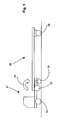
- At least one unloadable axle (35) is provided to take over a load portion in a heavily laden vehicle; this axle and at least the drive axle (34, with a rotation arrow) of the vehicle are as air suspension axles, each with at least one, the vehicle body over the axis supporting air spring bellows (2a, 2b) Fig. 2 educated.
- At least these axes (35, 34) are equipped with an electronic level control device equipped, by means of which a target level, namely a predeterminable distance between the vehicle body and the axles, is maintained as the actual level regardless of changing load.
- At least the drive axle and the at least one unloadable axle (35) are equipped with a load sensing device by, as explained below, the air pressure prevailing in the at least one air spring bellows provided for an air-suspended axle is measured by sensor means.
- the intended for the traction help vehicle can either be designed as a single vehicle or as towing vehicle of a vehicle train, consisting of towing vehicle and trailer, in the exemplary embodiment Fig. 1 this vehicle consists of the towing vehicle (37) which is coupled to the semitrailer trailer (38).
- the tractor is designed as a 6x2 vehicle, it has a front axle (33) and the axes explained above, namely the unloadable axle (35) and the drive axle (34).
- the unloadable axle (35) is arranged in the embodiment between the drive axle (34) and the front axle (33), it is designed as a lift axle and in Fig. 1 drawn in unloaded and off-hook condition.
- the relieving axis may alternatively be designed as a trailing axle;
- a relieving axle can be arranged in the direction of travel both in front of and behind the drive axle (in comparison to a towing axle, a lifting axle still has at least one, usually pneumatic, lifting cylinder).
- the trailer (38) is equipped in the embodiment with a fixed axis (36).
- a traction help is used to increase the traction of the towing vehicle (37) when starting, if in unfavorable friction ratio of the road (low ⁇ -friction in eg wet or ice) propulsive force transferable from the wheels of the drive axle (34) on the road Approaching is exceeded and at least one wheel of the drive axle (34) begins to spin:
- the axle load on the drive axle (43) is increased by, as indicated by an arrow (39), by relieving the unloaded axle (35) an axle load displacement to the drive axle (34) takes place.
- the current axle loads for the drive axle (34) and for the unloadable axle (35) are determined as Achslast weight forces in the wake of this axle load shift, and the discharge of the unloaded axle (35) is carried out as in contrast to the usual pressure control as force control.
- the axle load of an axle represents this axle load weight force exerted by the vehicle body on the relevant axle; for an air-suspended axle, the axle load weight force is determined by the product of the air pressure p L prevailing in the air spring bellows associated with that axle and the sum A w of the actual surfaces (effective effective surface area at that level) of those air spring bellows.
- the need for activating the traction help occurs when starting one or both wheels of the drive axle (34) of the towing vehicle (37) start to spin, and then a traction increase request is made to a traction control unit responsible for traction, which either by the driver with actuation of a corresponding switch, or automatically by a z. B. trained as ABS / ASR control unit, the slip of the drive axle (34) of the towing vehicle (37) monitoring electronic control unit takes place when it detects the onset of spin and z. B. via suitable data bus means the traction increase request as a message to the towing vehicle control unit.
- the present axle loads for the drive axle (34) and for the unloadable axle (35) are determined in a first step according to the invention.
- the test shows that the current axle load of the drive axle (34) is not smaller (ie either equal to or greater) than its maximum axle load, then a further axle load shift is not possible and there is no activation of the traction increase made. If the test shows that the current axle load is less than the maximum axle load, then in a third step, the traction increase is activated and the unloaded axle (35) is unloaded.
- the pressure in the relief bellows associated with the unloadable axle (35) is reduced and the reduction of the load released by the reduction is transmitted to the drive axle (34); by the axle load shift (39) so on the drive axle (34) resting axle load is increased.
- the axle load displacement (8) which is carried out in temporal steps, it is continuously checked by force comparison, ie after each step, whether the maximum permissible axle load of the drive axle (34) is undershot, reached or exceeded.
- the axle load shift (39) is performed only to a maximum of the condition that the maximum permissible axle load of the drive axle (34) is complied with, and then the axle load shift (39) is terminated: At the drive axle (34) is now the maximum permissible axle load weight adjusted for the starting aid traction increase.
- the towing vehicle control unit with valve means for ventilation, with the bellows and the pressure sensor means for the unloadable axle (35) forms a control loop through which a specified value of the axle load weight force for this axis as the actual value is set.
- Achslastverlagerung is determined after adjusting this specified by the setpoint axle load weight on the unloadable axle (35) via the drive axle (34) associated sensor measuring means on the drive axle (34) prevailing axle load; the pressure initially measured there is also converted into an axle load weight, and then the above-described force comparison is performed, after which either the axle load shift is completed, or further steps of the axle load shift are required.
- Regulating the "correct" axle load for traction assistance also allows for the legal differences in the axle loads allowed for traction assistance in different countries, as they apply in those countries; In a given country, the traction help is then carried out in compliance with the statutory axle loads applicable in that country.
- These country-specific axle loads are stored by parameter in the memory of the towing vehicle control unit and are set in the respective country via a manually or automatically controlled via a GPS position detection dialing device for carrying out the traction help in this country.
- axle load weights for the support shaft (34) and the unloadable axle (35).
- these determinations are made several times and the calculation method described below makes it possible to calculate the axle load weight forces in the non-linear lift-load characteristic of air bellows with only a few operations without the use of divisions, so that a common Microcontroller as the computing unit of the towing vehicle control unit can easily perform these computational steps without being overloaded.
- this represents the indicator axle
- the indicator axle represents the unloadable Axle (35) for determining the axle load weights for the unloadable axle (35);
- the calibration axis correction functions assigned to the axle (34) and the loadable axle (35) are respectively assigned to these axles, as explained below for an exemplary display vehicle axle.
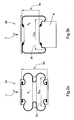
- FIG. 2 Two typical embodiments of air bellows are shown Fig. 2a shows an air spring bellows (2a) in the embodiment as a bellows, and Fig. 2b shows an embodiment as a rolling bellows (2b); Both air bellows are shown in a state in which they are filled by the above-mentioned effect of the electronic level control device with a certain amount of air to maintain the actual level.
- the effective diameter D W (3) changes both statically with the height of the actual level and dynamically with the rebound and rebound, starting from a selected actual level (bellows spring characteristic).
- the fact that this level influence is different for both types of bellows is due to the comparison of both types of bellows Fig. 2 spontaneously apparent;
- the effective diameter D W (3a) in the case of the bellows (2a) the folding state changes, and thus the effective diameter D W (3a), and in the case of the rolling bellows (2b) the rolling bellows (2b) formed as a pliable membrane buckles over the support element depending on the level height (4), so that also results in a level-height-dependent change in the effective diameter D W (3b).
- the level height influence on the effective diameter D W (3) and thus on the effective area A W of an air spring bellows (2) is thus dependent on the type of bellows; the invention is applicable to a level influence on the effective area of a bellows of any kind, and the nature of this influence for the application of the invention need not be known.
- the axle load weight F (1) is determined according to formula [2];
- a specific calibration level h O is defined for the actual level (5), and for this calibration level there is a specific effective area A WO , which represents a calibration area.
- a WO represents a calibration area.
- the calibration level z. B. the normal level of the vehicle to be selected for the ride; alternatively it is z. B. also possible to provide the smallest actual level as a calibration level.
- the invention is based on a specific axle load characteristic for the respective display vehicle axle, namely a characteristic curve describing the axle load weight F (1) above the bellows pressure p L.
- axle load characteristics may be calculated based on the characteristics of the air bags used and the mechanical dimensions established for the selected design (essentially those of the linkages) of axle and vehicle body.
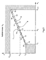
- this axle load characteristic can also be detected metrologically, as shown in the drawing Fig. 3 is shown.
- the vehicle is driven on an axle load scale such that the two wheels of the indicator vehicle axle are free on the left and right weighing platforms of the axle load scale. Then z.
- load eg., Cement weight plates
- the axle load weight F (1) determined by the axle load balance and the pressure p L in the air spring bellows become, as in Fig. 3 represented in the F / p L diagram.
- the minimum pressure at which an air spring bellows is just filled so far to prevent its mechanical destruction and the lowest possible axle load weight F 0 is exerted on the air spring bellows in this state is, in the example to Fig. 3 , in five steps (11, 12, 13, 14, 15) the load is gradually increased and the measuring points F x of the respectively measured axle load weights are plotted against the corresponding set bellows pressures p x , so that the permissible total weight for the vehicle axle is effective in the upper measuring stage (15) and, accordingly, the air spring bellows (2) with the maximum permissible pressure p z_G the maximum permissible axle load weight F z_G acts.
- the load is preferably but not necessarily in steps of the same height (16, 17, 18, 19, 20) again lowered, resulting in the same way a branch line (7) for falling pressure results (shown in phantom with arrow after bottom left), which, for reasons of frictional hysteresis in mechanics, is shifted in the direction of higher axle load weights F as compared to the characteristic branch (6).
- the Achslast-curve branch (6) for increasing pressure and the Achslastkennlinienzweigzweig (7) for falling pressure results in the Achslastkennline (8) as a basis for determining the axle load weight F (1) according to the invention.
- the stepwise lifting (10 to 15) and the stepwise lowering (16 to 20) can also be performed several times to measuring errors due to hysteresis to average out and increase the accuracy of the axle load characteristic (8);
- more than 5 levels can be selected to increase accuracy, while with reduced accuracy requirements less than 5, z. B. 3 levels can be selected.
- the axle load characteristic (8) as an average characteristic between the characteristic branches (6) and (7) represents with good approximation a straight line piece between the smallest force F 0 at the pressure p 0 and the maximum permissible force F z_G at the pressure p z_G .
- the effective area A W is present, which is determined by means of a correction function from the calibration area A W0 .
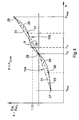
- This calibration area correction function k describes the dependence of the effective area A W of the air suspension bellows assigned to the display vehicle axle on this current actual level h of the vehicle body. For the correction of the calibration surface A W0 then the current actual level h is used in the calibration area correction function k.
- this calibration area correction function k (9) is advantageously designed as a ratio of the effective area A W of the air spring bellows to the calibration area A W0 ; on the ordinate is the correction function k, and on the abscissa the level h is plotted.
- the correction surface correction function (9) is after Fig. 4 metrologically determined.
- the calibration level h 0 is initially set after loading the display vehicle axle with the specified load on the display vehicle axle. At this load, starting from the calibration height h 0 , the level height is then reduced once to the minimum height h min by reducing or increasing the air spring bellows pressure p L and once increased to the maximum level height h max ; for each set level height h the air spring bellows pressure p L is measured and with the onset of this pressure p L in formula [7], the value k of the calibration surface correction function (9) is obtained Fig. 4 for this current level h. The combination of all the correction values k thus determined above the height h of the level gives the curve (9) of the calibration area correction function Fig. 4 ,
- the calibration area correction function (9) can also be formed by a polygonal line (10a or 10b) from straight line sections (21, 21). 22 or 23, 24, 25, 26) are approximated.
- a straight line section is defined by a first interpolation point of a surface calibration value at a first actual level and a second interpolation point of a surface calibration value at a second actual level, and at least one straight line section is provided for the traverse.
- two straight line sections (21, 22) are provided, wherein for the first interpolation point (27) of the area calibration value for the first straight line section (21) the minimum level height h min and for the second interpolation point (28) of the area calibration value (numerical value "1 ") the calibration height h 0 is selected. Similarly, for the first interpolation point (28) of the surface calibration value of the second straight line section (22), the calibration height h 0 and for the second interpolation point of the surface calibration value, the maximum level height h max is selected.
- the simplified polygon (10a) with the two straight sections (21, 22) by measuring the air bag pressure at only two other level heights, namely at the minimum level height h min and at the maximum level height h max determinable. Because the minimum and maximum level heights represent limit positions and possibly are not exactly adjusted, a level in the range of the minimum and maximum level height h min and h max can be set in its place.
- the two further interpolation points (30 and 31) are provided whose current height levels z. B. approximately in the middle of the areas between the minimum level height h min and the calibration height h 0 or between the calibration height h 0 and the maximum level height h max are.
- the traverse is therefore formed from the four straight sections (23, 24, 25, 26) and provides a better approximation compared to the traverse (10a).
- the accuracy is improved by introducing only two further points with the total of five interpolation points, the traverse (10b) approximates to a correction surface correction function (9) with its comparatively complex level influence with very good accuracy.
Landscapes
- Engineering & Computer Science (AREA)
- Mechanical Engineering (AREA)
- Chemical & Material Sciences (AREA)
- Combustion & Propulsion (AREA)
- Transportation (AREA)
- Vehicle Body Suspensions (AREA)
Description
Die Erfindung betrifft eine Vorrichtung zur Steuerung der Achslast von Fahrzeugen entsprechend dem Oberbegriff des Patentanspruchs 1.The invention relates to a device for controlling the axle load of vehicles according to the preamble of
Eine derartige Achslast-Steuervorrichtung ist aus der
Bei Fahrzeugen, die mit einer Anfahrhilfe nach der vorstehend erläuterten Schrift ausgestattet sind, können sowohl alle Achsen als auch nur die Triebachse und die entlastbare Achse (Ausführung als Schlepp- oder als Liftachse) zusätzlich mit einer elektronischen Niveauregelung ausgerüstet sein; dann wird der Druck in den Luftfederbälgen dieser Achsen durch eine elektronische Niveauregel-Steuereinheit eingeregelt, die bewirkt, dass ein vorgegebenes Soll-Niveau zwischen Aufbau und Achsen durch Einspeisung eines dieser Höhe entsprechenden Druckes in den zugeordneten Luftfederbälgen über Ventilmittel eingestellt wird.In vehicles that are equipped with a traction aid according to the above-described document, both all axes and only the drive axle and the unloadable axle (execution as a towing or as a lift axle) may be additionally equipped with an electronic level control; then the pressure in the air bellows of these axles is adjusted by an electronic level control unit which causes a predetermined target level between structure and axles to be adjusted by supplying a pressure corresponding to this level in the associated air bellows via valve means.
Ist die entlastbare Achse des Fahrzeugs z. B. bei starker Beladung zur Tragkraftunterstützung aktiviert, dann werden ihre Luftfederbälge mit den Triebachsen-Luftfederbälgen über die Niveauregel-Steuereinheit zur Höhenangleichung ebenfalls be- und entlüftet, wobei es für diese Regelung z. B. die folgenden Ausführungsformen gibt:Is the unloadable axle of the vehicle z. B. activated with heavy load for supporting support, then their bellows with the drive axle air spring bellows on the level control unit for height adjustment also aerated and vented, it being for this scheme z. For example, there are the following embodiments:
Bei einer Druckgleichheitsregelung (1. Ausführungsform) wird der Druck in den Luftfederbälgen der entlastbaren und der Triebachse auf den gleichen Druckwert eingeregelt, wozu nur ein Drucksensor erforderlich ist.In a pressure equality control (1st embodiment), the pressure in the bellows of the unloadable and the drive axle is adjusted to the same pressure value, to which only a pressure sensor is required.
Dagegen werden bei einer Druckverhältnisregelung (2. Ausführungsform) die Drücke in den Luftfederbälgen der entlastbaren und den Luftfederbälgen der Antriebsachse auf ein bestimmtes Druckverhältnis eingeregelt, und hierzu sind dann zwei Drucksensoren erforderlich.In contrast, in a pressure ratio control (2nd embodiment), the pressures in the bellows of the relieved and the air suspension bellows of the drive axle adjusted to a certain pressure ratio, and this then two pressure sensors are required.
Bei beiden Ausführungsformen kann eine Anfahrhilfe in der Art der Achslastverlagerung der vorbekannten Schrift durchgeführt werden; auch bei diesen Lösungen wird der in den Luftfederbälgen der Triebachse herrschende Druck als Maß für deren Achslast benutzt.In both embodiments, a traction aid in the type of axle load displacement of the prior art font can be performed; Even in these solutions, the prevailing in the bellows of the drive axle pressure is used as a measure of their axle load.
Unter Zugrundelegung von Luftfederbälgen üblicher Bauart besteht bei allen diesen Lösungen, bei denen die Achslastermittlung nur auf dem in den Triebachsen-Luftfederbälgen herrschenden Druck beruht, der Nachteil, dass die "feste" Zuordnung eines Drucks zu einer Achslast nur für eine Niveauhöhe, üblicherweise für das Fahrniveau, gilt.On the basis of air bellows of conventional design is in all these solutions in which the axle load is based only on the pressure prevailing in the drive axle bellows pressure, the disadvantage that the "fixed" assignment of a pressure to an axle load only for a level height, usually for the Driving level, applies.
Wenn z. B. das Fahrzeug abgesenkt ist oder ein zweites Fahrniveau gewählt ist, gilt diese festgelegte Achslast-Druck-Beziehung nicht mehr, und so wird bei der Anfahrhilfe die zulässige Achslast entweder über- oder unterschritten. Bei einer Unterschreitung wird mögliche Traktion "verschenkt" und bei einer Überschreitung werden gesetzliche Bestimmungen verletzt.If z. B. the vehicle is lowered or a second driving level is selected, this fixed axle load-pressure relationship is no longer valid, and so the traction help either exceeds or falls below the permissible axle load. In case of a shortfall possible traction is "given away" and if exceeded, legal regulations are violated.
Der Erfindung liegt deshalb die Aufgabe zugrunde, eine Anfahrhilfe derart zu verbessern, dass sie bei jeder Niveauhöhe die gesetzlich zulässigen Vorgaben erfüllt.The invention is therefore based on the object to improve a traction so that it meets the statutory requirements at each level height.
Diese Aufgabe wird durch die im Patentanspruch 1 angegebene Erfindung gelöst; Weiterbildungen und vorteilhafte Ausführungsbeispiele der Erfindung sind in den Unteransprüchen angegeben.This object is achieved by the invention defined in
Die Erfindung hat den Vorteil, dass bei der Anfahrhilfen-Achslastverlagerung immer korrekte, der wirklichen Beladung der zugehörigen Achsen entsprechende Werte berücksichtigt werden; mit der Erfindung wird weiter der Nachteil der Höhenabhängigkeit der Achslastverlagerung bei der Anfahrhilfe nach dem Stand der Technik beseitigt.The invention has the advantage that in the start-up aid Achslastverlagerung always correct, the actual loading of the associated axes corresponding values are taken into account; With the invention, the disadvantage of the height dependence of the Achslastverlagerung is further eliminated in the traction of the prior art.
Eine Weiterbildung der Erfindung hat den Vorteil, dass auch die sich bei einer Niveauhöhenveränderung ändernde Hub-/Tragkraft-Charakteristik der Luftfederbälge bei der Bestimmung der Anfahrhilfe berücksichtigt ist.A further development of the invention has the advantage that the lifting / carrying capacity characteristic of the air spring bellows which changes in the event of a level height change is also taken into account in the determination of the traction aid.
Eine hierauf aufbauende Weiterbildung der Erfindung hat den Vorteil, dass unterschiedliche Hub-/Tragkraft-Kennlinien von unterschiedlichen Balgkonstruktionen berücksichtigt werden können.A refinement of the invention based thereon has the advantage that different lifting / carrying capacity characteristics of different bellows constructions can be taken into account.
Eine Weiterbildung der Erfindung hat den Vorteil, dass spezifische, für verschiedene Länder geltende maximale Achslasten per Parameter einstellbar sind; darauf basierend kann entsprechend weiteren Weiterbildungen der Erfindung die für die Triebachse während der Anfahrhilfe geltende maximale Achslast vorteilhafterweise mit einer länderspezifischen zeitlichen und/oder geschwindigkeitsabhängigen Begrenzung versehen werden.A development of the invention has the advantage that specific, applicable for different countries maximum axle loads are adjustable by parameters; Based on this, according to further developments of the invention, the maximum axle load valid for the drive axle during the traction aid can advantageously be provided with a country-specific temporal and / or speed-dependent limitation.
Die Erfindung wird im folgenden anhand eines Ausführungsbeispiels, das in der Zeichnung dargestellt ist, näher erläutert.The invention will be explained in more detail below with reference to an embodiment shown in the drawing.
Es zeigen:
- Fig. 1
- Die Funktion der Anfahrhilfen-Traktionserhöhung durch Verlagerung von Achslast am Beispiel eines Zugfahrzeugs;
- Fig. 2
- für luftgefederte Achsen verwendete Luftfederbälge in zwei typischen Ausbildungen;
- Fig. 3
- eine messtechnisch ermittelte Achslastkennlinie für die Luftfederbälge einer luftgefederten Achse;
- Fig. 4
- eine Funktion zur Korrektur einer zur Achslastbestimmung verwendeten Kalibrierfläche eines Luftfederbalgs über dem aktuellen Ist-Niveau des Fahrzeugaufbaus.
- Fig. 1
- The function of the traction aid traction increase by shifting axle load using the example of a towing vehicle;
- Fig. 2
- Air suspension bellows used for air suspension axles in two typical designs;
- Fig. 3
- a metrologically determined axle load characteristic curve for the air spring bellows of an air-suspended axle;
- Fig. 4
- a function for correcting a calibration surface of an air spring bellows used for axle load determination above the current actual level of the vehicle body.
Bei einem für das erfindungsgemäße Anfahrhilfen-Steuerungsverfahren geeigneten Fahrzeug nach
Das für die Anfahrhilfe vorgesehene Fahrzeug kann entweder als Einzelfahrzeug oder als Zugfahrzeug eines Fahrzeugzuges, bestehend aus Zugfahrzeug und Anhängefahrzeug, ausgebildet sein, im Ausführungsbeispiel nach
Das Anhängefahrzeug (38) ist im Ausführungsbeispiel mit einer festen Achse (36) ausgerüstet.The trailer (38) is equipped in the embodiment with a fixed axis (36).
Eine Anfahrhilfe dient zur Erhöhung der Traktion des Zugfahrzeugs (37) beim Anfahren, wenn bei ungünstigem Reibungsverhältnis der Fahrbahn (geringe µ-Reibwerte bei z. B. Nässe oder Eis) die von den Rädern der Triebachse (34) auf die Fahrbahn übertragbare Vortriebskraft beim Anfahren überschritten wird und mindestens ein Rad der Triebachse (34) durchzudrehen beginnt: Zur Abhilfe wird in diesem Fall die Achslast auf die Triebachse (43) erhöht, indem, wie durch einen Pfeil (39) angedeutet, durch Entlastung der entlastbaren Achse (35) eine Achslastverschiebung zur Triebachse (34) erfolgt.A traction help is used to increase the traction of the towing vehicle (37) when starting, if in unfavorable friction ratio of the road (low μ-friction in eg wet or ice) propulsive force transferable from the wheels of the drive axle (34) on the road Approaching is exceeded and at least one wheel of the drive axle (34) begins to spin: To remedy this, the axle load on the drive axle (43) is increased by, as indicated by an arrow (39), by relieving the unloaded axle (35) an axle load displacement to the drive axle (34) takes place.
Erfindungsgemäß werden im Zuge dieser Achslastverschiebung die aktuellen Achslasten für die Triebachse (34) und für die entlastbare Achse (35) als Achslast-Gewichtskräfte bestimmt, und die Entlastung der entlastbaren Achse (35) wird als im Gegensatz zur üblichen Druckregelung als Kraftregelung durchgeführt.According to the invention, the current axle loads for the drive axle (34) and for the unloadable axle (35) are determined as Achslast weight forces in the wake of this axle load shift, and the discharge of the unloaded axle (35) is carried out as in contrast to the usual pressure control as force control.
Die Achslast einer Achse stellt diese Achslast-Gewichtskraft dar, die vom Fahrzeugaufbau auf die betreffende Achse ausgeübt wird; für eine luftgefederte Achse wird die Achslast-Gewichtskraft durch das Produkt aus dem in den dieser Achse zugeordneten Luftfederbälgen herrschenden Luftdruck pL und der Summe Aw der aktuellen Flächen (bei der vorliegenden Niveauhöhe aktuell geltenden wirksamen Flächen) dieser Luftfederbälge bestimmt. Der Luftdruck pL wird über einen Drucksensor erfasst, so dass sich mit der bekannten gesamten wirksamen Fläche AW die Achslast-Gewichtskraft für eine luftgefederte Achse nach folgender Gleichung bestimmt:![]()
![]()
Das Bedürfnis zur Aktivierung der Anfahrhilfe tritt auf, wenn beim Anfahren eines oder beide Räder der Triebachse (34) des Zugfahrzeugs (37) durchzudrehen beginnen, und dann wird eine Traktionserhöhungs-Anforderung an eine für die Anfahrhilfe zuständige Zugfahrzeug-Steuereinheit gestellt, welche entweder durch den Fahrer mit Betätigung eines entsprechenden Schalters, oder automatisch durch eine z. B. als ABS-/ASR-Steuereinheit ausgebildete, den Schlupf der Triebachse (34) des Zugfahrzeugs (37) überwachende elektronische Steuereinheit erfolgt, wenn diese das beginnende Durchdrehen erkennt und z. B. über geeignete Datenbusmittel die Traktionserhöhungs-Anforderung als Botschaft an die Zugfahrzeug-Steuereinheit stellt.The need for activating the traction help occurs when starting one or both wheels of the drive axle (34) of the towing vehicle (37) start to spin, and then a traction increase request is made to a traction control unit responsible for traction, which either by the driver with actuation of a corresponding switch, or automatically by a z. B. trained as ABS / ASR control unit, the slip of the drive axle (34) of the towing vehicle (37) monitoring electronic control unit takes place when it detects the onset of spin and z. B. via suitable data bus means the traction increase request as a message to the towing vehicle control unit.
Nach Vorliegen einer Traktionserhöhungs-Anforderung werden erfindungsgemäß in einem ersten Schritt die aktuellen Achslasten für die Triebachse (34) und für die entlastbare Achse (35) bestimmt.After the presence of a traction increase request, the present axle loads for the drive axle (34) and for the unloadable axle (35) are determined in a first step according to the invention.
Es wird dann in einem zweiten Schritt geprüft, ob die aktuelle Achslast der Triebachse (34) kleiner ist als ihre zulässige maximale Achslast.It is then checked in a second step, if the current axle load of the drive axle (34) is smaller than their permissible maximum axle load.
Wenn die Prüfung ergibt, dass die aktuelle Achslast der Triebachse (34) nicht kleiner (d. h. entweder gleich noch größer) als ihre maximale Achslast ist, so ist eine weitere Achslastverlagerung nicht möglich und es wird keine Aktivierung der Traktionserhöhung vorgenommen. Ergibt die Prüfung, dass die aktuelle Achslast kleiner ist als die maximale Achslast, so wird in einem dritten Schritt die Traktionserhöhung aktiviert und es wird eine Entlastung der entlastbaren Achse (35) vorgenommen.If the test shows that the current axle load of the drive axle (34) is not smaller (ie either equal to or greater) than its maximum axle load, then a further axle load shift is not possible and there is no activation of the traction increase made. If the test shows that the current axle load is less than the maximum axle load, then in a third step, the traction increase is activated and the unloaded axle (35) is unloaded.
Bei dieser Entlastung wird der Druck in den der entlastbaren Achse (35) zugeordneten Luftfederbälgen verringert und der durch die Verringerung "frei werdende" Lastanteil wird auf die Triebachse (34) übertragen; durch die Achslastverlagerung (39) wird also die auf der Triebachse (34) ruhende Achslast erhöht. Während der in zeitlichen Schritten durchgeführten Achslastverlagerung (8) wird per Kraftvergleich laufend, d. h. nach jedem Schritt jeweils überprüft, ob die maximal zulässige Achslast der Triebachse (34) unterschritten, erreicht oder überschritten wird. Die Achslastverlagerung (39) wird nur bis maximal dem Zustand durchgeführt, dass die maximal zulässige Achslast der Triebachse (34) eingehalten ist, und dann wird die Achslastverlagerung (39) beendet: An der Triebachse (34) ist nun die maximal zulässige Achslast-Gewichtskraft für die Anfahrhilfen-Traktionserhöhung eingeregelt.In this discharge, the pressure in the relief bellows associated with the unloadable axle (35) is reduced and the reduction of the load released by the reduction is transmitted to the drive axle (34); by the axle load shift (39) so on the drive axle (34) resting axle load is increased. During the axle load displacement (8), which is carried out in temporal steps, it is continuously checked by force comparison, ie after each step, whether the maximum permissible axle load of the drive axle (34) is undershot, reached or exceeded. The axle load shift (39) is performed only to a maximum of the condition that the maximum permissible axle load of the drive axle (34) is complied with, and then the axle load shift (39) is terminated: At the drive axle (34) is now the maximum permissible axle load weight adjusted for the starting aid traction increase.
Hierzu sei ergänzt, dass die Zugfahrzeug-Steuereinheit mit Ventilmitteln zur Be- und Entlüftung, mit den Luftfederbälgen und den Druck-Sensormitteln für die entlastbare Achse (35) einen Regelkreis bildet, durch den ein für diese Achse vorgegebener Sollwert der Achslast-Gewichtskraft als Istwert eingestellt wird. Bei jedem Schritt der Achslastverlagerung wird jeweils nach Einstellung dieser per Sollwert vorgegebenen Achslast-Gewichtskraft an der entlastbaren Achse (35) über die der Triebachse (34) zugeordneten Sensor-Messmittel die an der Triebachse (34) herrschende Achslast ermittelt; der dort zunächst gemessene Druck wird ebenfalls in eine Achslast-Gewichtskraft umgerechnet, und dann wird der oben erläuterte Kraftvergleich durchgeführt, nach dem entweder die Achslastverlagerung beendet ist, oder noch weitere Schritte der Achslastverlagerung erforderlich sind.It should be added that the towing vehicle control unit with valve means for ventilation, with the bellows and the pressure sensor means for the unloadable axle (35) forms a control loop through which a specified value of the axle load weight force for this axis as the actual value is set. At each Step of Achslastverlagerung is determined after adjusting this specified by the setpoint axle load weight on the unloadable axle (35) via the drive axle (34) associated sensor measuring means on the drive axle (34) prevailing axle load; the pressure initially measured there is also converted into an axle load weight, and then the above-described force comparison is performed, after which either the axle load shift is completed, or further steps of the axle load shift are required.
Mit der Regelung der "richtigen" Achslast bei der Anfahrhilfe lassen sich auch die gesetzlichen Unterschiede bei den für die Anfahrhilfe zugelassenen Achslasten in verschiedenen Ländern, wie sie in diesen Ländern gelten, berücksichtigen; in einem bestimmten Land wird die Anfahrhilfe dann unter Einhaltung der in diesem Land geltenden gesetzlich festgelegten zulässigen Achslasten durchgeführt.Regulating the "correct" axle load for traction assistance also allows for the legal differences in the axle loads allowed for traction assistance in different countries, as they apply in those countries; In a given country, the traction help is then carried out in compliance with the statutory axle loads applicable in that country.
Diese länderspezifischen Achslasten werden per Parameter im Speicher der Zugfahrzeug-Steuereinheit abgelegt und werden im jeweiligen Land über eine manuell oder automatisch über eine GPS-Positionserfassung gesteuerte Wähleinrichtung für die Durchführung der Anfahrhilfe in diesem Land eingestellt.These country-specific axle loads are stored by parameter in the memory of the towing vehicle control unit and are set in the respective country via a manually or automatically controlled via a GPS position detection dialing device for carrying out the traction help in this country.
Auf diese Weise können dann auch die in verschiedenen Ländern geltenden weiteren Begrenzungen, nämlich zeitlichen Begrenzungen für die Anfahrhilfen-Traktionserhöhung (z. B. <90 Sekunden) oder/und z. B. Begrenzungen der Anfahrhilfen-Traktionserhöhung auf eine maximale Geschwindigkeit des Fahrzeugs, die bei der Anfahrhilfe unterschritten werden muss (z. B. <30 km/h) berücksichtigt werden, indem diese Größen als weitere länderspezifische Parameter zur Durchführung der Anfahrhilfe gespeichert sind.In this way, the other limitations that apply in various countries, namely time limits for the traction aid traction increase (eg <90 seconds) or / and z. B. Limits the traction aid traction increase to a maximum speed of the vehicle, which must be fallen below in the traction (eg <30 km / h) are taken into account by these variables are stored as other country-specific parameters for performing traction.
Nach der vorstehenden Erläuterung des grundsätzlichen Verfahrens der Achslastverlagerung wird im folgenden auf eine vorteilhafte Bestimmung der Achslast-Gewichtskräfte für die Tragachse (34) und die entlastbare Achse (35) eingegangen. Im Rahmen der oben erläuterten schrittweisen Achslastverlagerung werden diese Bestimmungen mehrfach durchgeführt und das nachstehend beschriebene Berechnungsverfahren erlaubt es, die Achslast-Gewichtskräfte bei der nichtlinearen Hub-Tragkraft-Charakteristik von Luftfederbälgen mit nur wenigen Rechenoperationen, ohne Verwendung von Divisionen zu berechnen, so dass ein üblicher Mikrocontroller als Recheneinheit der Zugfahrzeug-Steuereinheit diese Rechenschritte problemlos ausführen kann, ohne überlastet zu werden.After the above explanation of the basic method of axle load shift is discussed below on an advantageous determination of the axle load weights for the support shaft (34) and the unloadable axle (35). In the context of the above-mentioned incremental axle load relocation, these determinations are made several times and the calculation method described below makes it possible to calculate the axle load weight forces in the non-linear lift-load characteristic of air bellows with only a few operations without the use of divisions, so that a common Microcontroller as the computing unit of the towing vehicle control unit can easily perform these computational steps without being overloaded.
Da das Rechenverfahren für beide Achsen gleich ist, natürlich mit unterschiedlichen Parametern, wird es mit Bezug auf
Bei der Bestimmung der Achslast-Gewichtskräfte für die Tragachse (34) stellt diese die Anzeige-Fahrzeugachse dar, während die Anzeige-Fahrzeugachse die entlastbare Achse (35) für die Bestimmung der Achslast-Gewichtskräfte für die entlastbare Achse (35) ist; dabei gelten für die Tragachse (34) und die entlastbare Achse (35) jeweils diesen Achsen zugeordnete Kalibrierflächen-Korrekturfunktionen, wie dies nachstehend für eine beispielhafte Anzeige-Fahrzeugachse erläutert ist.In determining the axle load weights for the axle (34), this represents the indicator axle, while the indicator axle represents the unloadable Axle (35) for determining the axle load weights for the unloadable axle (35); In this case, the calibration axis correction functions assigned to the axle (34) and the loadable axle (35) are respectively assigned to these axles, as explained below for an exemplary display vehicle axle.
In
Entsprechend Formel [1] ist die wirksame Fläche dieser Luftfederbälge AW und in ihnen herrscht in diesem Zustand der Druck pL, sodass sich für die Achslast-Gewichtskraft F (1) nach ![]()
![]()
Hierbei bestimmt sich die wirksame Fläche Aw aus dem wirksamen Durchmesser Dw (3a, 3b) des Luftfederbalgs:
Wie dem Fachmann bekannt ist, ändert sich der wirksame Durchmesser DW (3) sowohl statisch mit der Höhe des Ist-Niveaus als auch dynamisch mit der Ein- und Ausfederung, ausgehend von einem gewählten Ist-Niveau (Balgfederkennlinie). Dass dieser Niveauhöheneinfluss für beide Balgtypen unterschiedlich ist, ist aus der Gegenüberstellung beider Balgtypen in
Wie erläutert, wird die Achslast-Gewichtskraft F (1) nach Formel [2] bestimmt; hierfür ist für das Ist-Niveau (5) ein bestimmtes Kalibrierniveau hO festgelegt, und für dieses Kalibrierniveau gibt es eine ganz bestimmte wirksame Fläche AWO, die eine Kalibrierfläche darstellt. Für das Kalibrierniveau kann z. B. das normale Niveau des Fahrzeugs für die Fahrt gewählt werden; alternativ ist es z. B. auch möglich, das kleinste Ist-Niveau als Kalibrierniveau vorzusehen.As explained, the axle load weight F (1) is determined according to formula [2]; For this purpose, a specific calibration level h O is defined for the actual level (5), and for this calibration level there is a specific effective area A WO , which represents a calibration area. For the calibration level z. B. the normal level of the vehicle to be selected for the ride; alternatively it is z. B. also possible to provide the smallest actual level as a calibration level.
Die Erfindung geht von einer bestimmten Achslastkennlinie für die jeweilige Anzeige-Fahrzeugachse aus, nämlich einer Kennlinie, die die Achslast-Gewichtskraft F (1) über dem Balgdruck pL beschreibt. Eine derartige Achslastkennlinie kann unter Zugrundelegung der Kenndaten der verwendeten Luftfederbälge und der festgelegten mechanischen Abmessungen für die gewählte Konstruktion (im Wesentlichen die der Anlenkungen) von Achse und Fahrzeugaufbau rechnerisch ermittelt werden. Alternativ kann diese Achslastkennlinie auch messtechnisch erfasst werden, wie dies in der Zeichnung
Zur messtechnischen Ermittlung der Achslastkennlinie wird das Fahrzeug auf eine Achslastwaage derart gefahren, dass die beiden Räder der Anzeige-Fahrzeugachse frei auf den linken und rechten Wägeplattformen der Achslastwaage stehen. Dann wird z. B. unter Verwendung eines Krans durch Auflegen von Last (z. B. von Zement-Gewichtsplatten) die Achslast stufenweise erhöht, und es wird für die Achslast jeder Stufe der Druck pL im Luftfederbalg (2) derart erhöht, dass sich das Kalibrierniveau ho einstellt. Die von der Achslastwaage ermittelte Achslast-Gewichtskraft F (1) und der Druck pL im Luftfederbalg werden, wie in
Ausgehend von einem Druck p0, dem minimalen Druck, bei dem ein Luftfederbalg gerade so weit befüllt ist, um seine mechanische Zerstörung zu verhindern und auf den Luftfederbalg in diesem Zustand vom Aufbau die kleinstmögliche Achslast-Gewichtskraft F0 ausgeübt wird, wird, im Beispiel nach
Die Verbindung dieser insgesamt 6 Messwerte (10, 11, 12, 13, 14, 15) ergibt in
Nach dieser stufenweisen Erhöhung wird die Last vorzugsweise aber nicht zwingend in Stufen gleicher Höhe (16, 17, 18, 19, 20) wieder erniedrigt, wodurch sich in gleicher Weise ein Kennlinienzweig (7) für abfallenden Druck ergibt (fein gestrichelt dargestellt mit Pfeil nach links unten), der aus Gründen der reibungsbedingten Hysterese in der Mechanik im Vergleich zum Kennlinienzweig (6) in Richtung höherer Achslast-Gewichtskräfte F verschoben ist.After this incremental increase, the load is preferably but not necessarily in steps of the same height (16, 17, 18, 19, 20) again lowered, resulting in the same way a branch line (7) for falling pressure results (shown in phantom with arrow after bottom left), which, for reasons of frictional hysteresis in mechanics, is shifted in the direction of higher axle load weights F as compared to the characteristic branch (6).
Durch Mittelbildung aus dem Achslast-Kennlinienzweig (6) für ansteigenden Druck und dem Achslastkennlinienzweig (7) für abfallenden Druck ergibt sich die Achslastkennline (8) als Grundlage zur Bestimmung der Achslast-Gewichtskraft F (1) nach der Erfindung. Es sei ergänzt, dass das stufenweise Anheben (10 bis 15) und das stufenweise Absenken (16 bis 20) auch mehrfach durchgeführt werden kann, um Messfehler durch Hystereseeinflüsse auszumitteln und die Genauigkeit der Achslastkennlinie (8) zu erhöhen; natürlich können zur Genauigkeitserhöhung auch mehr als 5 Stufen gewählt werden, während bei verringerten Genauigkeitsanforderungen auch weniger als 5, z. B. 3 Stufen gewählt werden können.By averaging from the Achslast-curve branch (6) for increasing pressure and the Achslastkennlinienzweigzweig (7) for falling pressure results in the Achslastkennline (8) as a basis for determining the axle load weight F (1) according to the invention. It should be added that the stepwise lifting (10 to 15) and the stepwise lowering (16 to 20) can also be performed several times to measuring errors due to hysteresis to average out and increase the accuracy of the axle load characteristic (8); Of course, more than 5 levels can be selected to increase accuracy, while with reduced accuracy requirements less than 5, z. B. 3 levels can be selected.
Die Achslastkennlinie (8) als gemittelte Kennlinie zwischen den Kennlinienzweigen (6) und (7) stellt mit guter Näherung ein Geradenstück zwischen der kleinsten Kraft F0 beim Druck p0 und der maximal zulässigen Kraft Fz_G beim Druck pz_G dar. Die Achslastkennlinie (8) ist durch die lineare Beziehung![]()
![]()
Für andere Niveauhöhen h als dem Kalibrierniveau h0 liegt statt der Kalibrierfläche AW0 die wirksame Fläche AW vor, welche mit Hilfe einer Korrekturfunktion aus der Kalibrierfläche AW0 bestimmt wird. Diese Kalibrierflächen-Korrekturfunktion k beschreibt die Abhängigkeit der wirksamen Fläche AW der der Anzeige-Fahrzeugachse zugeordneten Luftfederbälge von diesem aktuellen Ist-Niveau h des Fahrzeugaufbaus. Für die Korrektur der Kalibrierfläche AW0 wird dann das aktuelle Ist-Niveau h in die Kalibrierflächen-Korrekturfunktion k eingesetzt.For level levels h other than the calibration level h 0 , instead of the calibration area A W0, the effective area A W is present, which is determined by means of a correction function from the calibration area A W0 . This calibration area correction function k describes the dependence of the effective area A W of the air suspension bellows assigned to the display vehicle axle on this current actual level h of the vehicle body. For the correction of the calibration surface A W0 then the current actual level h is used in the calibration area correction function k.
Wie in
Einführung der Kalibrierflächen-Korrekturfunktion k(h) in Gleichung [4]:
Da eine rechnerische Bestimmung des Niveauhöheneinflusses auf die wirksame Fläche eines Luftfederbalges wegen der vielen hierzu benötigten Einflussgrößen, die zunächst nicht bekannt sind, einerseits aufwendig ist und andererseits auch wegen der Nichtlinearitäten in diesen Einflussgrößen die Gefahr besteht, dass ein rechnerisch bestimmtes Ergebnis mit der Praxis nicht hinreichend im Einklang steht, wird die Korrekturflächen-Korrekturfunktion (9) nach
Die einfachste Methode stellt hierbei die Ermittlung bei einer festen Last dar, d. h. bei Belastung der Anzeige-Fahrzeugachse mit einer festen Achslast-Gewichtskraft Fconst, für die z. B. die Hälfte der maximal zulässigen Achslast-Gewichtskraft Fz_G gewählt wird:![]()
![]()
Durch Einsetzen von Gleichung [6] in Gleichung [5] ergibt sich für die Korrekturflächen-Korrekturfunktion k (h) :
Zur Messung wird nach Beladung der Anzeige-Fahrzeugachse mit der festgelegten Last an der Anzeige-Fahrzeugachse zunächst das Kalibrierniveau h0 eingestellt. Bei dieser Last wird nun, ausgehend von der Kalibrierhöhe h0, durch Verringerung bzw. Erhöhung des Luftfederbalg-Drucks pL die Niveauhöhe einmal bis zur minimalen Höhe hmin verringert und einmal bis zur maximalen Niveauhöhe hmax erhöht; für jede eingestellte Niveauhöhe h wird der Luftfederbalg-Druck pL gemessen und mit Einsetzen dieses Drucks pL in Formel [7] ergibt sich der Wert k der Kalibrierflächen-Korrekturfunktion (9) nach
Um den messtechnischen Aufwand zu verringern, kann die Kalibrierflächen-Korrekturfunktion (9) auch durch einen Polygonzug (10a bzw. 10b) aus Geradenabschnitten (21, 22 bzw. 23, 24, 25, 26) angenähert werden. Hierbei ist ein Geradenabschnitt durch einen ersten Stützpunkt eines Flächen-Kalibrierwerts an einem ersten Ist-Niveau und einen zweiten Stützpunkt eines Flächen-Kalibrierwerts an einem zweiten Ist-Niveau festgelegt, und für den Polygonzug ist mindestens ein Geradenabschnitt vorgesehen.In order to reduce the metrological outlay, the calibration area correction function (9) can also be formed by a polygonal line (10a or 10b) from straight line sections (21, 21). 22 or 23, 24, 25, 26) are approximated. Here, a straight line section is defined by a first interpolation point of a surface calibration value at a first actual level and a second interpolation point of a surface calibration value at a second actual level, and at least one straight line section is provided for the traverse.
Für den Polygonzug (10a) nach
Für den Polygonzug (10b) der Kalibrierflächen-Korrekturfunktion nach
Claims (12)
- Method for controlling a start-assist in a vehicle which is embodied either as an individual vehicle or as a traction vehicle (37) of a vehicle train composed of a traction vehicle and a trailer vehicle, in which in addition to a drive axle (34) at least one relievable axle (35) is provided, wherein at least the drive axle (34) and the at least one relievable axle (35) has air-suspension axles, each with at least one air spring bellows (3a, 3b) which supports the vehicle body via the axle, and the drive axle (34) and relievable axle (35) also have a load-sensing device, wherein a setpoint ride level, specifically a predefined vehicle body-axle distance is maintained as an actual ride level by means of an electronic ride level control device, having the following features:a) after a traction-increasing request has been submitted, the current axle loads for the drive axle (34) and the at least one relievable axle (35) are determined in a first step;b) in a second step it is tested whether the current axle load of the drive axle (34) is lower than its permissible maximum axle load;c) if the current axle load of the drive axle (34) is not lower than its maximum axle load, the increase in traction is not activated; andd) if the current axle load is lower than the maximum axle load, in a third step the increase in traction is activated and a process (39) of relieving the at least one relievable axle (35) is performed,characterized in that
the current axle loads for the drive axle (35) and the at least one relievable axle (35) are determined as axle load weight forces and the relieving of the at least one relievable axle (35) is carried out as a force control, and in that when a relieving process takes place the pressure in the air spring bellows assigned to the relievable axle (35) is reduced and the proportion of the load which is freed up by the reduction is transmitted to the drive axle (34), wherein during the axle load displacement (8) which is carried out in chronological steps, it is continuously checked by comparison of forces whether the maximum permissible axle load of the drive axle (34) is undershot, reached or exceeded, and wherein the axle load displacement (39) is carried out only at maximum to the state in which the maximum permissible axle load of the drive axle (34) is complied with. - Method according to Claim 1, characterized in that the axle load weight force is determined for an axle, a display vehicle axle (34, 35), by means of the pressure (pL) in the air spring bellows (3a, 3b) assigned to the axle and by means of the effective area (AW) of these air spring bellows which are assigned to the axle.
- Method according to Claim 2, characterized in that the axle load weight force for the display vehicle axle (34, 35) is determined by the product of the pressure (pL) in the air spring bellows (3a, 3b) assigned to the axle and the effective area (AW) of these air spring bellows assigned to the display vehicle axle (34, 35).
- Method according to Claim 3, characterized by the following features:a) for the determination of the effective area (AW) of the air spring bellows (3a, 3b) assigned to the display vehicle axle (34, 35) a calibration area (Awo) is provided;b) the calibration area (Awo) is determined as an effective area of the air spring bellows (3a, 3b) assigned to the display vehicle axle in the case of a calibration ride level (h0) as an actual ride level;c) the calibration area (Awo) is corrected by a function (k) which describes the dependence of the effective area (Aw), assigned to the display vehicle axle, of the air spring bellows on the current actual ride level (h) of the vehicle body;d) the current actual ride level (h) is inserted into the calibration area correction function in order to correct the calibration area (Awo).
- Method according to Claim 4, characterized in that a normal ride level is defined as a calibration ride level (h0).
- Method according to Claim 4, characterized in that the smallest actual ride level (hmin) is defined as a calibration ride level.
- Method according to one more of Claims 4 to 6, characterized in that the calibration function (k, 9) is determined by the ratio of the effective area (Aw) of the air spring bellows in the current actual ride level (h) to the calibration area (Awo) in the calibration ride level (h0).
- Method according to Claim 7, characterized in that the calibration function (k) is embodied as a polygon course (10a, 10b) formed from straight sections, wherein a straight section (21) is defined by a first reference point (27) of an area calibration value at a first actual ride level (hmin) and a second reference point (28) of an area calibration value at a second actual ride level (h0), which reference points (27, 28) bound the straight section (21), and at least one straight section (21) is provided in the polygon course.
- Method according to Claim 8, characterized in that two straight sections, a first straight section (21) and a second straight section (22) are provided for the polygon course (10a), wherein an actual ride level in the region of the smallest actual ride level (hmin) is defined ovided for the first straight section (21) for the first reference point (27), and the calibration ride level (h0) is defined for the second reference point (28), and wherein the calibration ride level (h0) for the second straight section (22) is defined for the first reference point (28), and an actual ride level in the region of the largest actual ride level (hmax) is defined for the second reference point (29).
- Method according to one or more of Claims 1 to 9, characterized in that the start-assist is carried out in a country by complying with the permissible axle loads which are legally defined as applicable in this country.
- Method according to one or more of Claims 1 to 10, characterized in that the time for the increase in traction for the start-assist is limited to a maximum time which is applicable in a country.
- Method according to one or more of Claims 1 to 11, characterized in that the increase in traction for the start-assist is limited to a maximum speed of the vehicle which is applicable for the start-assist in a country.
Applications Claiming Priority (2)
| Application Number | Priority Date | Filing Date | Title |
|---|---|---|---|
| DE102004010548.0A DE102004010548B4 (en) | 2004-03-04 | 2004-03-04 | Vehicle traction assist |
| DE102004010548 | 2004-03-04 |
Publications (3)
| Publication Number | Publication Date |
|---|---|
| EP1571014A2 EP1571014A2 (en) | 2005-09-07 |
| EP1571014A3 EP1571014A3 (en) | 2009-10-07 |
| EP1571014B1 true EP1571014B1 (en) | 2012-05-09 |
Family
ID=34745385
Family Applications (1)
| Application Number | Title | Priority Date | Filing Date |
|---|---|---|---|
| EP05000088A Expired - Lifetime EP1571014B1 (en) | 2004-03-04 | 2005-01-05 | Start-assist for a vehicle |
Country Status (2)
| Country | Link |
|---|---|
| EP (1) | EP1571014B1 (en) |
| DE (1) | DE102004010548B4 (en) |
Cited By (4)
| Publication number | Priority date | Publication date | Assignee | Title |
|---|---|---|---|---|
| DE202014003501U1 (en) | 2014-04-29 | 2014-09-25 | Expresso Deutschland Gmbh | Motor-driven industrial truck for traction of a load carrier |
| US9533540B2 (en) | 2014-03-04 | 2017-01-03 | Hendrickson Usa, L.L.C. | Parking brake interlock for automatic lift axle |
| US10611206B2 (en) | 2013-03-13 | 2020-04-07 | Hendrickson Usa, L.L.C. | Air suspension control system |
| WO2024068012A1 (en) * | 2022-09-30 | 2024-04-04 | Volvo Truck Corporation | Controlling suspension of a set of wheels |
Families Citing this family (13)
| Publication number | Priority date | Publication date | Assignee | Title |
|---|---|---|---|---|
| DE102005054626A1 (en) * | 2005-11-16 | 2007-05-24 | Contitech Luftfedersysteme Gmbh | Determining the load capacity of air spring bellows |
| DE102006016989B8 (en) * | 2006-04-11 | 2011-12-15 | Knorr-Bremse Systeme für Nutzfahrzeuge GmbH | Method for leveling a vehicle body by regulating the air mass in the bellows |
| DE102011015510A1 (en) | 2010-06-30 | 2012-01-05 | Wabco Gmbh | Method and device for controlling a traction aid of a vehicle |
| MX2013002269A (en) * | 2010-08-26 | 2013-09-06 | Gen Electric | Systems and methods for weight transfer in a vehicle. |
| US8313111B2 (en) | 2010-08-26 | 2012-11-20 | General Electric Company | Systems and methods for weight transfer in a vehicle |
| WO2014094915A1 (en) * | 2012-12-21 | 2014-06-26 | John Victor Gano | Active control of a vehicle-ground interface |
| DE102013008656A1 (en) | 2013-05-18 | 2014-11-20 | Wabco Gmbh | Method for traction control of a pneumatically suspended vehicle and air suspension system for carrying out the method |
| WO2015176732A1 (en) * | 2014-05-22 | 2015-11-26 | Wabco Gmbh | Method for controlling the traction of a pneumatically sprung vehicle and air suspension system for carrying out the method |
| CN106494153B (en) * | 2016-12-19 | 2018-10-26 | 李霜杰 | A kind of vehicle and its assistant drive system of starting to walk |
| KR102577429B1 (en) * | 2019-04-05 | 2023-09-13 | 볼보 트럭 코퍼레이션 | Method and control unit for determining parameters representing road performance of road segments supporting vehicles |
| DE102019111187A1 (en) | 2019-04-30 | 2020-11-05 | Wabco Gmbh | Method for determining an axle load on a vehicle with mechanical suspension |
| CN114964017B (en) * | 2022-05-31 | 2024-12-27 | 中国第一汽车股份有限公司 | Vehicle height calibration method, system and storage medium for air suspension |
| DE102023113656A1 (en) * | 2023-05-24 | 2024-11-28 | Zf Cv Systems Europe Bv | Method for operating a lifting axle of a towing vehicle-trailer combination, computer program and/or computer-readable medium, control device, trailer vehicle |
Family Cites Families (18)
| Publication number | Priority date | Publication date | Assignee | Title |
|---|---|---|---|---|
| DE19821036A1 (en) * | 1998-05-11 | 1999-11-18 | Wabco Gmbh | Device and method for controlling operating functions of a vehicle |
| DE3428867A1 (en) | 1984-08-04 | 1986-02-13 | Wabco Westinghouse Fahrzeugbremsen GmbH, 3000 Hannover | AIR SPRING DEVICE FOR VEHICLES |
| US4783089A (en) * | 1984-10-15 | 1988-11-08 | C & K Venture Income I-Coast | Air spring control system and method |
| DE3545222A1 (en) * | 1985-12-20 | 1987-06-25 | Bosch Gmbh Robert | Starting aid for motor vehicles with air suspension |
| DE3724696A1 (en) * | 1987-07-25 | 1989-02-02 | Bosch Gmbh Robert | METHOD FOR REGULATING A COMPRESSED AIR SUSPENSION |
| DE3824366A1 (en) * | 1988-07-19 | 1990-01-25 | Iveco Magirus | Device for the control of a leaf spring tandem axle of a commercial vehicle as a function of the load |
| DE3925196A1 (en) | 1989-07-29 | 1991-02-07 | Iveco Magirus | START-UP AID FOR AIR-SUSPENSED MULTI-AXLE VEHICLES WITH LIFTABLE ADDITIONAL AXLE |
| DE3929788A1 (en) * | 1989-09-07 | 1991-03-21 | Man Nutzfahrzeuge Ag | LIFTABLE DOUBLE AXLE UNIT |
| JP2939322B2 (en) * | 1990-10-26 | 1999-08-25 | トヨタ自動車株式会社 | Vehicle load detector |
| US5373445A (en) * | 1992-03-05 | 1994-12-13 | Ford Motor Company | Method and apparatus for determining dynamic force within an air spring suspension |
| DE4222922A1 (en) * | 1992-07-11 | 1993-07-01 | Daimler Benz Ag | AIR-SUSPENSIONED DOUBLE AXLE UNIT |
| DE4317847B4 (en) * | 1993-05-28 | 2007-07-19 | Wabco Gmbh | Device for controlling the towing axle of a vehicle |
| DE4327764C2 (en) * | 1993-08-18 | 2002-08-14 | Knorr Bremse Systeme | Air suspension system |
| JP3513940B2 (en) * | 1994-10-26 | 2004-03-31 | いすゞ自動車株式会社 | Start assist device control device |
| US6308793B1 (en) * | 1999-03-22 | 2001-10-30 | Alliedsignal Truck Brake Systems Co. | Proportional load transfer valve for suspension control with 6×2 automatic traction control |
| DE10029332B4 (en) * | 2000-06-20 | 2007-05-24 | Continental Aktiengesellschaft | Measurement of the load condition of a motor vehicle |
| SE519500C2 (en) * | 2001-06-21 | 2003-03-04 | Scania Cv Ab | Device for a truck and a truck |
| US20050148258A1 (en) | 2003-12-31 | 2005-07-07 | Jayant Chakravarty | Absorbent structures having enhanced flexibility |
-
2004
- 2004-03-04 DE DE102004010548.0A patent/DE102004010548B4/en not_active Expired - Lifetime
-
2005
- 2005-01-05 EP EP05000088A patent/EP1571014B1/en not_active Expired - Lifetime
Cited By (4)
| Publication number | Priority date | Publication date | Assignee | Title |
|---|---|---|---|---|
| US10611206B2 (en) | 2013-03-13 | 2020-04-07 | Hendrickson Usa, L.L.C. | Air suspension control system |
| US9533540B2 (en) | 2014-03-04 | 2017-01-03 | Hendrickson Usa, L.L.C. | Parking brake interlock for automatic lift axle |
| DE202014003501U1 (en) | 2014-04-29 | 2014-09-25 | Expresso Deutschland Gmbh | Motor-driven industrial truck for traction of a load carrier |
| WO2024068012A1 (en) * | 2022-09-30 | 2024-04-04 | Volvo Truck Corporation | Controlling suspension of a set of wheels |
Also Published As
| Publication number | Publication date |
|---|---|
| DE102004010548B4 (en) | 2022-09-08 |
| DE102004010548A1 (en) | 2005-09-22 |
| EP1571014A2 (en) | 2005-09-07 |
| EP1571014A3 (en) | 2009-10-07 |
Similar Documents
| Publication | Publication Date | Title |
|---|---|---|
| EP1571014B1 (en) | Start-assist for a vehicle | |
| EP2429841B1 (en) | Device and method for controlled damping of a vehicle | |
| EP2591928B1 (en) | Adjustment of the bearing load of a central axle trailer | |
| DE69031794T2 (en) | Suspension control system | |
| DE4017223C2 (en) | ||
| DE69005073T2 (en) | Pressure control device of a suspension. | |
| EP3727905B1 (en) | Method for determining an axle load on a mechanically and/or pneumatically or hydraulically suspended vehicle and vehicle | |
| EP1980429B1 (en) | Method and device for stabilising the roll of a motor vehicle | |
| DE4017222A1 (en) | METHOD AND SYSTEM FOR CONTROLLING ACTIVE SUSPENSIONS OF A VEHICLE | |
| DE3907111A1 (en) | CONTROL FOR THE SUSPENSION OF A MOTOR VEHICLE | |
| EP1844961A1 (en) | Method for the level control of the chassis of a vehicle by adjusting the air mass in the pneumatic spring | |
| DE102005059205B4 (en) | Vehicle rollover prevention control device | |
| DE3935991A1 (en) | METHOD FOR CONTROLLING ACTIVE SUSPENSION SPRINGS FOR VEHICLES WITH SELF-DRIVE | |
| EP0779167B1 (en) | Level control device | |
| DE102018119748A1 (en) | Method for controlling a hydropneumatic suspension of a vehicle crane | |
| DE19648176B4 (en) | A method of controlling the vibration dampers in a vehicle having a level control device | |
| DE102010032046B4 (en) | Method for leveling an air-suspended motor vehicle and device therefor | |
| EP1571429B1 (en) | Device for displaying the axle load. | |
| DE10225940A1 (en) | Process for controlling a level control system | |
| DE102017208213A1 (en) | Tire pressure control system of a vehicle | |
| DE102019114259A1 (en) | Method for calibrating a load-displacement curve of a mechanically sprung vehicle axle | |
| DE102020111520B3 (en) | Method and device for determining the coefficient of friction between a vehicle wheel and the roadway | |
| EP3795959B1 (en) | Method for calibrating axle or wheel load sensors | |
| EP3647085B1 (en) | Motor vehicle and method for adjusting the height of a height-adjustable motor vehicle | |
| EP3145736B1 (en) | Method to control the traction of a pneumatically suspended vehicle and pneumatic spring system to implement this method |
Legal Events
| Date | Code | Title | Description |
|---|---|---|---|
| PUAI | Public reference made under article 153(3) epc to a published international application that has entered the european phase |
Free format text: ORIGINAL CODE: 0009012 |
|
| AK | Designated contracting states |
Kind code of ref document: A2 Designated state(s): AT BE BG CH CY CZ DE DK EE ES FI FR GB GR HU IE IS IT LI LT LU MC NL PL PT RO SE SI SK TR |
|
| AX | Request for extension of the european patent |
Extension state: AL BA HR LV MK YU |
|
| RAP1 | Party data changed (applicant data changed or rights of an application transferred) |
Owner name: WABCO GMBH |
|
| PUAL | Search report despatched |
Free format text: ORIGINAL CODE: 0009013 |
|
| AK | Designated contracting states |
Kind code of ref document: A3 Designated state(s): AT BE BG CH CY CZ DE DK EE ES FI FR GB GR HU IE IS IT LI LT LU MC NL PL PT RO SE SI SK TR |
|
| AX | Request for extension of the european patent |
Extension state: AL BA HR LV MK YU |
|
| RIC1 | Information provided on ipc code assigned before grant |
Ipc: B60G 17/052 20060101ALI20090831BHEP Ipc: B62D 61/12 20060101ALI20090831BHEP Ipc: B60G 5/00 20060101ALI20090831BHEP Ipc: B60G 17/015 20060101AFI20050609BHEP |
|
| 17P | Request for examination filed |
Effective date: 20100407 |
|
| AKX | Designation fees paid |
Designated state(s): DE FR GB IT NL SE |
|
| 17Q | First examination report despatched |
Effective date: 20100609 |
|
| GRAP | Despatch of communication of intention to grant a patent |
Free format text: ORIGINAL CODE: EPIDOSNIGR1 |
|
| GRAS | Grant fee paid |
Free format text: ORIGINAL CODE: EPIDOSNIGR3 |
|
| GRAA | (expected) grant |
Free format text: ORIGINAL CODE: 0009210 |
|
| AK | Designated contracting states |
Kind code of ref document: B1 Designated state(s): DE FR GB IT NL SE |
|
| REG | Reference to a national code |
Ref country code: GB Ref legal event code: FG4D Free format text: NOT ENGLISH |
|
| REG | Reference to a national code |
Ref country code: NL Ref legal event code: T3 |
|
| REG | Reference to a national code |
Ref country code: SE Ref legal event code: TRGR |
|
| REG | Reference to a national code |
Ref country code: DE Ref legal event code: R096 Ref document number: 502005012702 Country of ref document: DE Effective date: 20120712 |
|
| PLBE | No opposition filed within time limit |
Free format text: ORIGINAL CODE: 0009261 |
|
| STAA | Information on the status of an ep patent application or granted ep patent |
Free format text: STATUS: NO OPPOSITION FILED WITHIN TIME LIMIT |
|
| 26N | No opposition filed |
Effective date: 20130212 |
|
| REG | Reference to a national code |
Ref country code: DE Ref legal event code: R097 Ref document number: 502005012702 Country of ref document: DE Effective date: 20130212 |
|
| REG | Reference to a national code |
Ref country code: FR Ref legal event code: PLFP Year of fee payment: 12 |
|
| REG | Reference to a national code |
Ref country code: FR Ref legal event code: PLFP Year of fee payment: 13 |
|
| REG | Reference to a national code |
Ref country code: FR Ref legal event code: PLFP Year of fee payment: 14 |
|
| PGFP | Annual fee paid to national office [announced via postgrant information from national office to epo] |
Ref country code: IT Payment date: 20200122 Year of fee payment: 16 Ref country code: GB Payment date: 20200127 Year of fee payment: 16 Ref country code: NL Payment date: 20200122 Year of fee payment: 16 Ref country code: SE Payment date: 20200127 Year of fee payment: 16 |
|
| PGFP | Annual fee paid to national office [announced via postgrant information from national office to epo] |
Ref country code: FR Payment date: 20200123 Year of fee payment: 16 |
|
| REG | Reference to a national code |
Ref country code: DE Ref legal event code: R081 Ref document number: 502005012702 Country of ref document: DE Owner name: ZF CV SYSTEMS EUROPE BV, BE Free format text: FORMER OWNER: WABCO GMBH, 30453 HANNOVER, DE Ref country code: DE Ref legal event code: R081 Ref document number: 502005012702 Country of ref document: DE Owner name: ZF CV SYSTEMS HANNOVER GMBH, DE Free format text: FORMER OWNER: WABCO GMBH, 30453 HANNOVER, DE |
|
| REG | Reference to a national code |
Ref country code: SE Ref legal event code: EUG |
|
| REG | Reference to a national code |
Ref country code: NL Ref legal event code: MM Effective date: 20210201 |
|
| GBPC | Gb: european patent ceased through non-payment of renewal fee |
Effective date: 20210105 |
|
| PG25 | Lapsed in a contracting state [announced via postgrant information from national office to epo] |
Ref country code: FR Free format text: LAPSE BECAUSE OF NON-PAYMENT OF DUE FEES Effective date: 20210131 Ref country code: NL Free format text: LAPSE BECAUSE OF NON-PAYMENT OF DUE FEES Effective date: 20210201 |
|
| PG25 | Lapsed in a contracting state [announced via postgrant information from national office to epo] |
Ref country code: SE Free format text: LAPSE BECAUSE OF NON-PAYMENT OF DUE FEES Effective date: 20210106 Ref country code: GB Free format text: LAPSE BECAUSE OF NON-PAYMENT OF DUE FEES Effective date: 20210105 |
|
| REG | Reference to a national code |
Ref country code: DE Ref legal event code: R081 Ref document number: 502005012702 Country of ref document: DE Owner name: ZF CV SYSTEMS EUROPE BV, BE Free format text: FORMER OWNER: ZF CV SYSTEMS HANNOVER GMBH, 30453 HANNOVER, DE |
|
| PG25 | Lapsed in a contracting state [announced via postgrant information from national office to epo] |
Ref country code: IT Free format text: LAPSE BECAUSE OF NON-PAYMENT OF DUE FEES Effective date: 20210105 |
|
| PGFP | Annual fee paid to national office [announced via postgrant information from national office to epo] |
Ref country code: DE Payment date: 20230131 Year of fee payment: 19 |
|
| P01 | Opt-out of the competence of the unified patent court (upc) registered |
Effective date: 20230528 |
|
| REG | Reference to a national code |
Ref country code: DE Ref legal event code: R119 Ref document number: 502005012702 Country of ref document: DE |
|
| PG25 | Lapsed in a contracting state [announced via postgrant information from national office to epo] |
Ref country code: DE Free format text: LAPSE BECAUSE OF NON-PAYMENT OF DUE FEES Effective date: 20240801 |
|
| PG25 | Lapsed in a contracting state [announced via postgrant information from national office to epo] |
Ref country code: DE Free format text: LAPSE BECAUSE OF NON-PAYMENT OF DUE FEES Effective date: 20240801 |